Neomigi 400 G - Welding machine GYS - Free user manual and instructions
Find the device manual for free Neomigi 400 G GYS in PDF.
Questions des utilisateurs sur Neomigi 400 G GYS
0 question sur cet appareil. Repondez a celles que vous connaissez ou posez la votre.
Poser une nouvelle question sur cet appareil
Download the instructions for your Welding machine in PDF format for free! Find your manual Neomigi 400 G - GYS and take your electronic device back in hand. On this page are published all the documents necessary for the use of your device. Neomigi 400 G by GYS.
USER MANUAL Neomigi 400 G GYS
This procedure is detailed in the wirefeeder manual.
INSTALLATION – FONCTIONNEMENT PRODUIT
ANOMALIES, CAUSES, REMÈDES
GENERAL INSTRUCTIONS These instructions must be read and fully understood before use. Do not carry out any alterations or maintenance work that is not directly specied in this manual. The manufacturer shall not be liable for any damage to persons or property resulting from use not in accordance with the instructions in this manual. In case of problems or queries, please consult a qualied tradesperson to correctly install the product. ENVIRONMENT This equipment should only be used for welding operations performed within the limits indicated on the information panel and/or in this manual. These safety guidelines must be observed. The manufacturer cannot be held responsible in the event of improper or dangerous use. The machine must be set up somewhere free from dust, acid, ammable gases or any other corrosive substances. This also applies to the machine’s storage. Ensure good air circulation when in use. Temperature range: Use between -10 and +40°C (+14 and +104°F). Store between -20 and +55°C (-4 and 131°F). Air humidity: Lower than or equal to 50% at 40°C (104°F). Lower than or equal to 90% at 20°C (68°F). Altitude: Up to 1000m above sea level (3,280 feet).
PROTECTING YOURSELF AND OTHERS
Arc welding can be dangerous and cause serious injury or death. Welding exposes people to a dangerous source of heat, light radiation from the arc, electromagnetic elds (caution to those using pacemakers) and risk of electrocution, as well as noise and fumes. To protect yourself and others, please observe the following safety instructions: To protect yourself from burns and radiation, wear insulating, dry and reproof clothing without lapels. Ensure the clothing is in good condition and that covers the whole body. Wear protective gloves which provide electrical and thermal insulation. Use welding protection and/or a welding helmet with a sucient level of protection (depending on the specic use). Protect your eyes during cleaning procedures. Contact lenses are specically forbidden. It may be necessary to section o the welding area with reproof curtains to protect the area from arc radiation and hot spatter. Inform people in the welding area not to stare at the arc rays or molten parts and to wear appropriate clothing for protection. Wear noise protection headphones if the welding process becomes louder than the permissible limit (this is also applicable to anyone else in the welding area). Keep hands, hair and clothing away from moving parts (the ventilation fan, for example). Never remove the cooling unit housing protections when the welding power source is live, the manufacturer cannot be held responsible inthe event of an accident. Newly welded parts are hot and can cause burns when handled. When maintenance work is carried out on the torch or electrode holder, ensure that it is suciently cold by waiting at least 10 minutes before carrying out any work. The cooling unit must be switched on when using a water-cooled torch to ensure that the liquid cannot cause burns. It is important to secure the working area before leaving it, in order to protect people and property.
WELDING FUMES AND GAS
The fumes, gases and dusts emitted by welding are harmful to health. Sucient ventilation must be provided and an additional air supply may be required. An air-fed mask could be a solution in situations where there is inadequate ventilation. Check the extraction system’s performance against the relevant safety standards. Caution: Welding in conned spaces requires safety monitoring from a safe distance. In addition, the welding of certain materials containing lead, cadmium, zinc, mercury or even beryllium can be particularly harmful. Remove any grease from the parts before welding. Cylinders should be stored in open or well-ventilated areas. They should be stored in an upright position and kept on a stand or trolley.EN
User manual NEOMIG-i 400 G / 500 G Translation of the original instructions Welding should not be carried out near grease or paint.
RISK OF FIRES AND EXPLOSIONS
Fully shield the welding area, ammable materials should be kept at least 11 metres away. Fire ghting equipment should be kept close to wherever the welding activities are being undertaken. Beware the expulsion of hot spatter or sparks, even through cracks, which can cause res or explosions. Keep people, ammable objects and pressurised containers at a safe distance. Welding in closed containers or tubes is to be avoided. If the containers or tubes are open, they must be emptied of all ammable or explosive materials (oil, fuel, gas residues, etc.). Grinding work must not be directed towards the source of the welding current or towards any ammable materials. GAS CYLINDERS Gas escaping from cylinders can cause suocation if there is too high a concentration of it in the welding area (ensure good ventilation). The machine must be transported in complete safety: gas cylinders must be closed and the welding power source turned o. They should be stored upright and supported to limit the risk of falling. Close the cylinder between uses. Beware of temperature variations and exposure to the sun. The cylinder must not come into contact with ames, arcs, torches, earth clamps or any other sources of heat or ignition. Be sure to keep it away from electrical and welding circuits. Never weld a pressurised cylinder. When opening the cylinder valve, keep your head away from the valve and ensure that the gas being used is suitable for the welding process. ELECTRICAL SAFETY The electrical network used must be earthed. Use the recommended fuse size from the rating plate. An electric shock can be the source of a serious accident, whether directly or indirectly, or even death. Never touch live parts connected to the live current, either inside or outside the power source casing unit (torches, clamps, cables, electrodes), as these items are connected to the welding circuit. Before opening the welding machine’s power source, disconnect it from the mains and wait two minutes to ensure that all the capacitors have fully discharged. Do not touch the torch or the electrode holder and the earth clamp at the same time. If the cables or torches become damaged, they must be replaced by a qualied and authorised person. Measure the cable cross-section according to the intended application. Always use dry and in-fact clothing to insulate yourself from the welding circuit. Alongside this, wear well-insulated footwear in all working environments. EMC CLASSIFICATION This Class A device is not intended for use in a residential environment where power is provided by the public low-voltage local supply network. Ensuring electromagnetic compatibilty may be dicult at these sites due to conducted, as well as radiated, radio frequency interference. Provided that the impedance of the public low-voltage supply network is less than Zmax = 0.29 Ohms at the common coupling point, this equipment complies with IEC 61000-3-11 and can be connected to public low-voltage electrical supply. It is the responsibility of the tter or operator of the equipment to ensure, by consulting the electricity distribution network provider if necessary, that the network impedance complies with impedance restrictions. This equipment complies with the IEC 61000-3-12 standard. ELECTROMAGNETIC INTERFERENCES An electric current passing through any conductor produces localised electric and magnetic elds (EMF). The welding current produces an electromagnetic eld around the welding circuit and the welding equipment. Electromagnetic elds (EMFs) can interfere with some medical devices, for example pacemakers. Protective measures must be taken for people with medical implants. For example, restricted access for onlookers or an individual risk assessment for welders. All welders should use the following guidelines to minimise exposure to the welding circuit’s electromagnetic elds:
- position the welding cables together - securing them with a clamp if possible;
- position yourself (head and body) as far away from the welding circuit as possible,
- never wrap the welding cables around your body,16 User manual NEOMIG-i 400 G / 500 G Translation of the original instructions
- do not position yourself between the welding cables. and keep both welding cables on your same side;
- connect the return cable to the workpiece, as close as possible to the area to be welded,
- do not work next to, sit or lean on the source of the welding current,
- do not transport the welding power source or wire feeder while welding. Pacemaker users should consult a doctor before using this equipment. Exposure to electromagnetic elds during welding may have other health eects that are not yet known. RECOMMENDATIONS FOR ASSESSING THE WELDING AREA AND EQUIPMENT General Information It is the user’s responsibilit to install and use the arc welding equipment according to the manufacturer’s instructions. If electromagnetic disturbances are detected, it is the user’s responsiblity to resolve the situation using the manufacturer’s technical support. In some cases, this corrective action may be as simple as earthing the welding circuit. In other cases, it may be necessary to construct an electromagnetic shield around the welding current source and around the entire workpiece by setting up input lters. In any case, electromagnetic interference should be reduced until it is no longer an inconvenience. Assessing the welding area Before installing arc welding equipment, the user should assess the potential electromagnetic problems in the surrounding area. The following should be taken into account: a) the presence of power, control, signal and telephone cables above, below and next to the arc welding equipment, b) radio and television receivers and transmitters, c) computers and other control equipment, d) critical safety equipment, e.g. the protection of industrial equipment, e) the health of nearby persons, e.g. those using of pacemakers or hearing aids, f) the equipment used for calibrating or measuring, g) the protection of other surrounding equipment. The operator has to ensure that the devices and equipment used in the same area are compatible with each other. This may require further protective measures; h) the time of day when welding or other operations are to be carried out. The size of the surrounding area to be taken into account will depend on the building’s structure and the other activities taking place there. The surrounding area may extend beyond the boundaries of the premises. Assessment of the welding equipment In addition to the assessment of the surrounding area, the arc welding equipment’s assessment can be used to identify and resolve cases of interference. It is appropriate that the assessment of any emissions should include in situ procedures as specied in Article 10 of CISPR 11. In situ measurements can also be used to conrm the eectiveness of mitigation measures. GUIDELINES ON HOW TO REDUCE ELECTROMAGNETIC EMISSIONS a. The mains power grid: Arc welding equipment should be connected to the mains power grid according to the manufacturer’s recommendations. If any interference occurs, it may be necessary to take additional precautionary measures such as ltering the mains power supply. Consider protecting the power cables of permanently installed arc welding equipment within a metal pipe or a similar casing. The power cable should be protected along its entire length. The shield should be connected to the welding power source to ensure that there is good electrical contact between the conduit and the welding power source enclosure. b. The maintenance of arc welding equipment: Arc welding equipment should be subject to routine maintenance as recommended by the manufacturer. All access points, service openings and bonnets should be closed and properly locked when the arc welding equipment is in use. The arc welding equipment should not be modied in any way, except for those modications and adjustments mentioned in the manufacturer’s instructions. The spark gap of arc starters and stabilisers should be adjusted and maintained according to the manufacturer’s recommendations. c. Welding cables: Cables should be as short as possible, placed close together either near or on the ground. d. Equipotential bonding: Consideration should be given to linking all metal objects in the surrounding area. However, metal objects connected to the workpiece increase the risk of electric shocks to the user if they touch both these metal parts and the electrode. It is necessary to insulate the operator from such metal objects. e. Earthing the workpiece: In cases where the part to be welded is unearthed for electrical safety reasons or due to its size and location, such as ship hulls or structural steel buildings, an earthed connection can reduce emissions in some cases, although not always. Care should be taken to avoid the earthing of parts which could increase the risk of injury to users or damage to other electrical equipment. If necessary, the workpiece’s connection should be earthed directly, but in some countries where a direct connection is not allowed, the connection should be made with a suitable capacitor chosen according to national regulations. f. Protection and protective casing: The selective protection and encasing of other cables and equipment in the surrounding area may limit interference problems. The safeguarding of the entire welding area may be considered for special applications. THE TRANSPORTING AND MOVING OF THE MACHINE’S POWER SOURCE The machine is equipped with two handles to facilitate transport, which requires two people. Do not use the cables or torch to move the machine. It should be moved in an upright position. Do not carry or transport the power source overhead of people or objects. Never lift the machine while there is a gas cylinder on the support shelf. Their transportation requirements are dierent.EN
- Place the welding power source on a oor with a maximum inclination of 10°.
- Provide sucient space to ventilate the welding power source and access the controls.
- Do not use in an area with conductive metal dust.
- The welding power source should be protected from heavy rain and not exposed to direct sunlight.
- The machine is IP23 rated, meaning: - the dangerous parts of the machine are protect against entry by objects greater than 12.5 mm and, - protection against the rain inclined at 60° towards the vertical. These devices can be used outside in accordance with the IP23 protection index. The power cables, extensions and welding cables must be fully uncoiled to prevent overheating. The manufacturer assumes no responsibility for damage to persons or objects caused by improper and dangerous use of this equipment. MAINTENANCE / RECOMMENDATIONS
- Maintenance should only be carried out by a qualied person. Annual maintenance is recommended.
- Switch o the power supply by pulling the plug and wait two minutes before working on the equipment.. Inside the macine, the voltages and currents are high and dangerous.
- Regularly remove the cover and blow out any dust. Take advantage of the opportunity to have the electrical connections checked with an insulated tool by a qualied professional.
- Regularly check the condition of the power cable. If the power cable is damaged, it must be replaced by the manufacturer, the after sales service team or an equally qualied person to avoid any danger.
- Leave the welding power source vents free for air intake and outow.
- Do not use this welding power source for thawing pipes, recharging batteries/storage batteries or starter motors.
INSTALLATION - USING THE PRODUCT
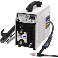
Only experienced personnel, authorised by the manufacturer, may carry out the machine’s set-up. During set-up, ensure that the power source is unplugged from the mains. Series or parallel power source connections are not allowed. It is recommended to use the welding cables supplied with the unit in order to obtain the optimum product settings. DESCRIPTION This machine is a three-phase power source for semi-automatic, software-supported welding (MIG or MAG), coated electrode welding (MMA) and refractory electrode welding (TIG). The use of a separate wire feeder is required (sold separately). DESCRIPTION OF THE EQUIPMENT (II)
5- Connector for external wire feeder control
POWER SWITCH This machine is tted with a 32A socket type EN 60309-1 which must only be used on a three-phase 400 V (50-60 Hz) four-wire earthed electrical installation. The absorbed eective current (I1e) is indicated on the device for optimum operating conditions. Check that the power supply and its protection (fuse and/or circuit breaker) are compatible with the current required to run the machine. In some countries, it may be necessary to change the plug to allow the use at maximum settings.
- The power source is designed to operate on 400V +/-15%. The unit enters protection mode if the supply voltage is less than 330Vrms or greater than 490Vrms (a fault code will appear on the display).
- Starting is done by pressing the START/STOP switch (On), and stopping is done by pressing the same switch (O). Warning! Never switch o the power supply while the unit is under load.
CONNECTING TO A POWER SOURCE
This equipment can be operated with electric generators provided that the auxiliary power supply meets the following requirements: - The voltage must be alternating with an RMS value of 400V +/- 15% and a peak voltage of less than 700V. - The frequency must be between 50 and 60 Hz. It is vital to check these conditions as many generators produce high voltage peaks that can damage equipment.18 User manual NEOMIG-i 400 G / 500 G Translation of the original instructions
USING EXTENSION LEADS
All extension leads must be of a suitable length and width that is appropriate to the equipment’s voltage. Use an extension lead that complies with national safety regulations. Input voltage Length - Cross-section of the extension cable (Length < 45m) 400 V 4mm²
CONNECTING OF THE INTERCONNECTION CABLE
Make sure the main welding power source switched o when connecting or disconnecting the wire feeder. Ensure the machine is unplugged from the mains, and then wait 2 minutes. For details of the wiring harness connection between the generator and the wire feeder, please refer to the separate wire feeder manual (optional). The diagrams below describe the minimum requirements for the various dierent welding processes. The user can leave any unused connections (gas connection in MMA welding, power cable on the wire feeder in MMA and TIG welding, etc.) if they wish. MIG-MAG welding (positive polarity) KOOLWELD 2 optionalEN
1 Control 1 Control 2 Power 2 Power 3 Gas 3 Gas 4 Water cooling MIG-MAG welding (negative polarity) MIG/MAG welding without gas shielding generally requires negative polarity. In this case, it is necessary to use the optional polarity reversal cable accessory (a). In any case, refer to the wire manufacturer’s recommendations for the choice of polarity for your MIG-MAG torch. KOOLWELD 2 optional
1 Control 1 Control 2 Power 2 Power 3 Water cooling q Reverse polarity cable (optional) q Reverse polarity cable (optional) MMA Welding Ensure that the polarities and welding intensities indicated on the electrode packaging are observed. Remove the electrode from the electrode holder when the machine is not in use. Do not connect the MIG-MAG or TIG torch when the machine is being used for MMA welding. KOOLWELD 2 optionalEN
1 Control 1 Control 2 Ground clamp or electrode holder 2 Ground clamp or electrode holder TIG welding (with TIG torch EURO connector) DC TIG welding requires protective gas shielding (Argon). Ensure that the torch is properly tted and that the consumables (vice grip pliers, collet bodies, diusers and nozzles) are not worn out. It is necessary to use the optional polarity reversal cable accessory (a). KOOLWELD 2 optional
1 Control 1 Control 2 Power 2 Power 3 Gas 3 Gas q Reverse polarity cable (optional) q Reverse polarity cable (optional) It is also possible to use an optional valve TIG torch. This must be connected to the negative polarity socket on the front of the power source (II-2).
5m 032439 10m 032446 OPTIONAL WIREFEEDER This product has to be equipped with a separate wire feeder WF 35 (ref. 075078) or WF 50 (option, ref. 075108). The connection between these two parts is made through a dedicated interconnection cable, available separately: Type of torch cooling Length Section Reference Air 5m 70mm² 075443 10m 70mm² 075450 95mm² 077553 Water 1.8m 70mm² 075467 5m 70mm² 075474 10m 70mm² 075481 95mm² 075504EN
The cooling unit is automatically detected by the machine. To deactivate the cooling unit (OFF), please refer to the interface manual. The safeguards provided by the cooling unit are to protect the torch and the user, and are as follows:
- Minimum coolant level.
- Minimum ow rate of coolant owing through the torch.
- Thermal protection of the coolant. Make sure that the cooling unit is turned o before disconnecting the inlet and outlet hoses for torch liquid. Coolant is harmful and irritates the eyes, mucous membranes and skin. Hot liquid can cause burns.
Dust lter (ref. 046580) with ltration to: 630 µm (0.63 mm). Please note that the use of this lter reduces the duty cycle of your machine. To avoid the risk of overheating due to clogged air vents, the dust lter should be cleaned on a regular basis. Unclip and clean with compressed air.
DEFECTS, CAUSES, AND SOLUTIONS
SYMPTOMS POSSIBLE CAUSES SOLUTIONS
The ow rate of the welding wire is not constant. Clogs blocking the opening. Clean the contact tube or replace it with non- stick material. The wire is slipping on the rollers. Reapply the non-stick product. One of the rollers is spinning. Check the tightness of the roller screw. The torch cable is twisted. The torch cable should be as straight as possible. The unwinding mechanism is not working. The spool’s brake or roller is too tight. Loosen the brake and rollers. Incorrect unwinding of the wire. Dirty or damaged wire guide. Clean or replace. Roller pin key is missing. Reposition the pin in its slot. Spool’s brake is too tight. Release the brake. No current or wrong welding current. Incorrect mains outlet connection. Check the plug connection and verify that the plug is connected to the power supply. Poor earth connection. Check the earthing cable (its connection and the condition of the clamp). Power problem. Check the torch trigger. Spooling problem. The wire jams after passing through the rollers. Crushed wire guide sheath. Check the wire-guide sheath and body of the torch.. Wire blockage in the torch. Replace or clean. No capillary tube. Check that the capillary tube is present. Wire speed too high. Reduce the wire speed.24 User manual NEOMIG-i 400 G / 500 G Translation of the original instructions The weld bead is porous. The gas ow is insucient. Adjustment range from 15 to 20 L / min. Clean the base metal. Gas cylinder empty. Replace it. Unsatisfactory gas quality. Replace it. Air circulation or wind inuence. Avoid draughts and protect the welding area. Gas nozzle is too clogged. Clean or replace the gas nozzle. Bad wire quality. Use a wire suitable for MIG/MAG welding. Condition of the welding surface is too poor (rusted, etc.). Clean the workpiece before welding. The gas is not connected. Check that the gas is connected to the power source’s inlet. Excessive sparks. Arc voltage is too low or too high. See welding settings. Poor earth connection. Check and position the earth clamp as close as possible to the area to be welded. Insucient gas protection. Adjust the gas ow. No gas coming from the torch. Poor gas connection. Check the connections of gas inlets. Check that the solenoid valve is working. Problem with the gas bottle Check the gas level. Check the gas supply. Error while downloading. The data on the USB stick is incorrect or corrupted. Check your data. Backup error. You have exceeded the maximum number of backups. You need to delete some programs. The number of backups is limited to 200. Automatic deletion of JOBS. Some of your JOBs have been deleted because they were incompatible with the new pre-installed user settings (synergies).
USB key error. There is no JOB detected on the USB stick. - The product’s memory space is full. Free up some space on the USB key. File error. The le does not match the pre-installed user settings (synergies) downloaded to the product. The le was created with pre-installed user settings (synergies) that are not present on the machine. Update problem The USB stick is not recognised. The visuali- sation of step 4 of the update procedure does not appear on the display.
1- Insert the USB key into its socket.
2- Turn on the power source.
3- Press and hold the 2 push-buttons (no. 2
and no. 3) on the HMI to force the update. WARRANTY CONDITIONS The warranty covers any defects or manufacturing faults for two years from the date of purchase (parts and labour). The warranty does not cover:
- Any other damage caused during transport.
- The general wear and tear of parts (i.e. : cables, clamps, etc.).
- Incidents caused by misuse (incorrect power supply, dropping or dismantling).
- Environment-related faults (such as pollution, rust and dust). In the event of a breakdown, please return the item to your distributor, along with: - dated proof of purchase (receipt, invoice, etc.), a note explaining the malfunction.DE
WAARSCHUWINGEN - VEILIGHEIDSINSTRUCTIES
INSTALLATIE - WERKING VAN HET APPARAAT
RYZYKO POŻARU I WYBUCHU
Warning ! Read the user manual before use.
Undulating current technology based source delivering direct curent.
Suitable for welding in an environment with an increased risk of electric shock. However this a machine should not placed in such an environment.
Direct welding current
Open circuit voltage
Duty cycle according to standard EN 60974-1 (10 minutes – 40°C).
Corresponding conventional welding current
Conventional voltage in corresponding loads.
Three-phase power supply 50 or 60Hz
Maximum rated power supply current (effective value).
Maximum effective power supply current.
Device complies with euro- peans directives, The EU declaration of conformity is available on our website (see cover page).
Equipment in compliance with British requirements. The British Declaration of Conformity is available on our website (see home page).
Equipment in conformity with Moroccan standards. The declaration Cم (CMIM) of conformity is available on our website (see cover page).
The device is compliant with standard EN60974-1 and EN60971-10 class A device.
This hardware is subject to waste collection according to the European directives 2012/19/EU. Do not throw out in a domestic bin !
This product should be recycled appropriately
EAEC Conformity marking (Eurasian Economic Community).
Temperature information (thermal protection)
The safety disconnection device is a combination of the power socket in coordination with the electrical installation. The user has to make sure that the plug can be reached.