
G1506S - Industrial control enclosure IFM - Free user manual and instructions
Find the device manual for free G1506S IFM in PDF.
| Product Type | Industrial control unit for safety detectors |
| Brand | IFM |
| Model | G1506S |
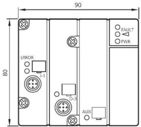
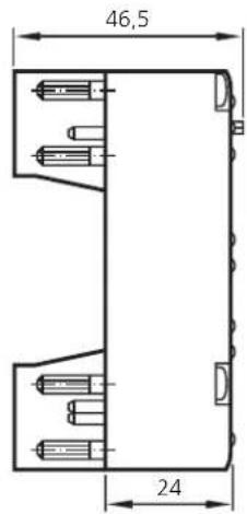
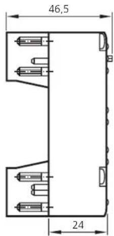
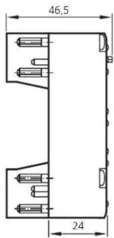
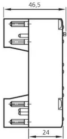
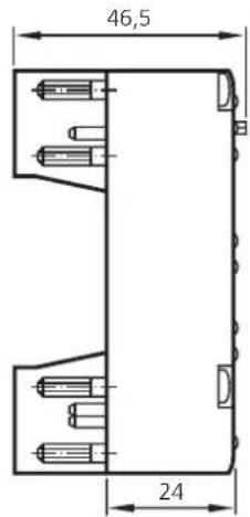
| Dimensions (H x W x D) | 80 x 90 x 46.5 mm |
| Power supply | AS-i: 26.5...31.6 V DC; external power supply: 24 V DC (15...30 V DC) |
| Current consumption | < 250 mA |
| Maximum number of inputs | 1 safety input (chain up to 8 detectors) |
| Switching output | 1 PNP output, 500 mA, non-safety (O-3) |
| Response time | < 220 ms |
| Safety classification | Category 4 according to EN 954-1 |
| Protection | IP 67 |
| Ambient temperature | -25...+55 °C |
| Relative humidity | < 95 % |
| Housing material | PBTP (Pocan) |
| Main functions | Redundant and diverse control of up to 8 safety detectors; evaluation and transmission of the safety code table via AS-Interface |
| Maintenance and cleaning | No maintenance required |
| Maximum service life | 10 years |
| Certifications | TÜV, CE, cULus |
| Addressing | Via addressing unit AC1144 or infrared |
| Weight | Approx. 150 g (estimate) |
Frequently Asked Questions - G1506S IFM
User questions about G1506S IFM
0 question about this device. Answer the ones you know or ask your own.
Ask a new question about this device
Download the instructions for your Industrial control enclosure in PDF format for free! Find your manual G1506S - IFM and take your electronic device back in hand. On this page are published all the documents necessary for the use of your device. G1506S by IFM.
USER MANUAL G1506S IFM
Operating instructions Evaluation unit for fail-safe switches with AS-Interface
natural_image
Top-down schematic of a device layout with labeled components (no text or symbols)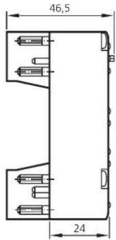
The operating instructions
... apply to the G1506S evaluation unit for fail-safe switches.
... are intended for authorised persons according to the EMC, low voltage directives and safety instructions.
... are part of the unit. They contain information about the correct handling of the product. Read them before use to familiarise yourself with operating conditions, installation and operation. Follow the safety instructions.
Contents
- Safety instructions ..... page 13
- Function and features ..... page 14
- Configuration requirements Hardware-dependent requirements..... page 14 Software-dependent requirements..... page 14
- Tests/approvals..... page 15
- Items supplied . . . . . . . . . . . . . . . . . . . . . . . . . . . . . . . . . . . . . . . . . . . . . page 15
- Description of the unit Operating elements and indicators .... page 16
- Setup Installation ..... page 17 Electrical connection ..... page 17 Parameter setting ..... page 17 Addressing ..... page 18
- Response times ..... page 18 Calculation of the total response time..... page 18
- Fault diagnosis Location by means of the indicators ..... page 19
- Maintenance/duration of use . . . . . . . . . . . . . . . . . . . . . . . . . . page 19
- Technical data ...... page 20
TÜV certificate.... page 62
Type test certificate . . . . . . . . . . . . . . . . . . . . . . . . . . . . . . . . . . . . . . . . . . . . . . page 63
EC Declaration of Conformity. . . . . . . . . . . . . . . . . . . . . . . . . . . . . . . . . . . . . page 64
cULus . . . . . . . . . . . . . . . . . . . . . . . . . . . . . . . . . . . . . . . . . . . . . . . . . . . . page 66
1. Safety instructions
Follow the operating instructions.
Non-observance of the instructions, operation which is not in accordance with use as prescribed below, incorrect installation or handling can affect the safety of people and equipment.
For mounting and prescribed use of the product the notes in the operating instructions must be carefully observed and the applicable technical standards relevant for the application have to be considered.
In case of non-observance of notes or standards, specially when tampering with and/or modifying the product any liability is excluded.
The unit must be installed, connected and put into operation by a qualified electrician trained in safety technology.
After installation of the system a complete function check must be carried out.
Disconnect the unit externally before handling it. Also disconnect any independently supplied relay load circuits.
For installation the requirements according to EN60204-1 must be observed.
In case of malfunction of the unit please contact the manufacturer. Tampering with the unit can seriously affect the safety of people and equipment. This is not permitted and leads to an exclusion of liability and warranty.
2. Function and features
The evaluation unit is a redundant diverse system to process a chain of sensors with up to 8 fail-safe switches.
The evaluation unit supplies/monitors the connected fail-safe switches and evaluates their switching status. If all fail-safe switches are fully operational and correctly damped, the evaluation unit transmits the safety code table to the AS-interface (8x4 bit data sequence).
The safety-related evaluation of the code table must be effected by a suitable safety monitor (e.g. AC001S, AC002S, AC003S, AC004S). The safe state is when no code is transmitted (static 0).
The evaluation unit complies with the category 4 according to EN 954-1 or the requirement class 5 according to DIN V 19250/DIN V 19251 and DIN V VDE 0801.

Depending on the safety components used the complete safety system can also be classified in a lower safety category!
Notes on functions and features
- AS-i profile S-7.B.E
• maximum number of evaluation units per master: 30
• AS-i chip according to the AS-interface version 2.1
3. Configuration requirements
The following requirements must be complied with when using the evaluation unit G1506S.
Hardware-dependent requirements
The safety requirements of the respective application must correspond to the requirements stated in these instructions. The specified technical data must be complied with.
By taking administrative measures in the application it must be ensured that a function check is carried out at least once a year. A function check is carried out by switching the AS-i supply voltage or the evaluation (data bit DO0, 0 = evaluation ON) briefly off.
In case of faults within the evaluation unit which result in the defined safe state, the evaluation unit must be replaced.
Software-dependent requirements
The complete description of the configuration of the AS-i safety monitor has to be taken into account!
4. Tests/approvals

The evaluation unit G1506S has been tested and certified by TÜV Informationstechnik.
The evaluation unit was developed and tested in accordance with the following directives and standards:
• 98/37/EEC machinery directive
• 89/336/EEC EMC directive
- 73/23/EEC or 93/68 low voltage directive
- DIN V VDE 0801 (1990) and amendment A1 (1994) Principles for computers in safety-related systems
- DIN V 19250 (1994) Requirement class AK 5, Fundamental safety aspects to be considered for measurement and control equipment
- DIN V 19251 (1995) MC protection equipment - Requirements and measures for safeguarded function
- EN 954-1 (1997) Category 4, Safety of machinery. Safety-related parts of control systems
5. Items supplied
1 evaluation unit G1506S,
1 cap for M12 sockets,
1 operating instructions G1506S, ifm no. 701702.
If one of the above-mentioned components is missing or damaged, please contact one of the ifm branch offices overleaf.
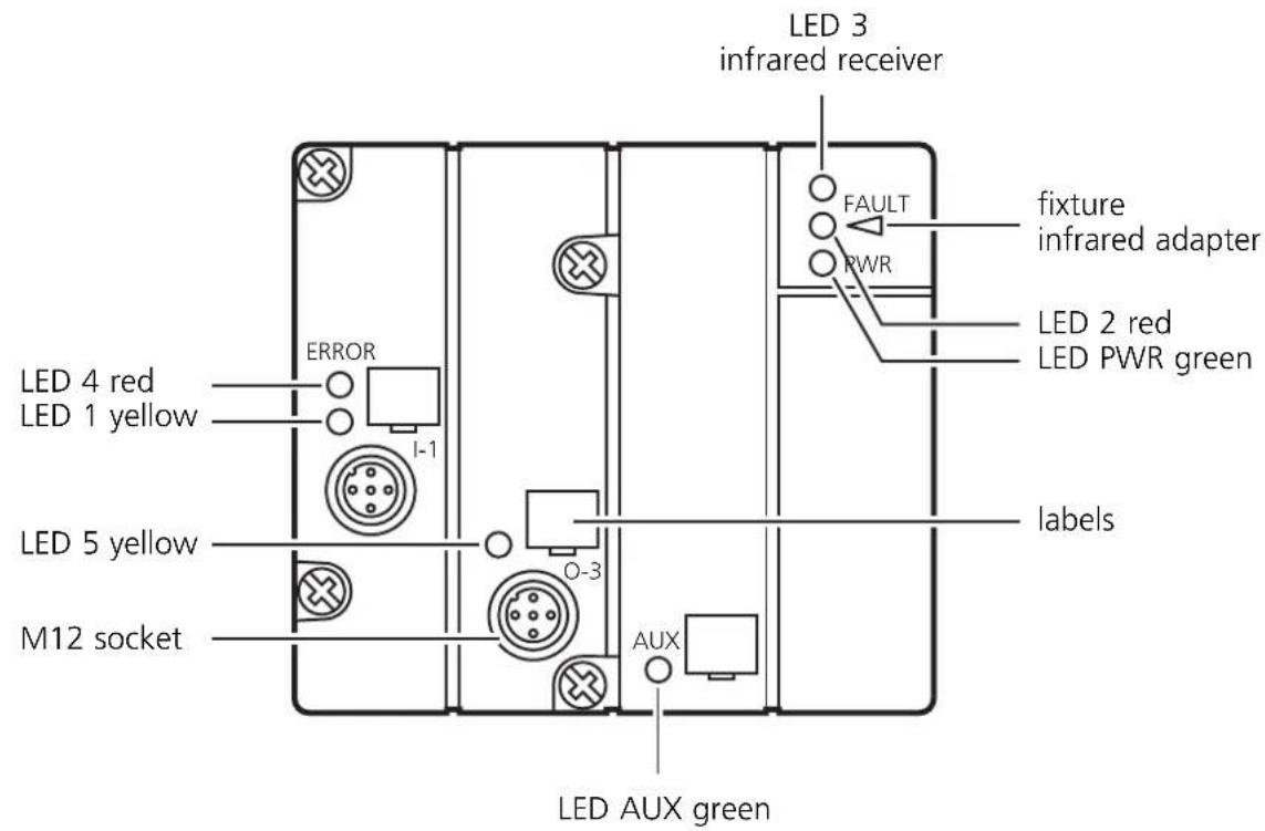
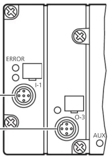
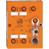
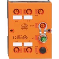
6. Description of the unit
Operating elements and indicators
| LED Colour Status Meaning | |
| 1 yellow on fail-safe switch or chain enabled | |
| 2 red on FAULTAS-i communication errorslave does not participate in the "normal"exchange of data, e.g. if slave address = 0flashing periphery fault, e.g. sensor supply overloadedor shorted | |
| 3 -- infrared receiver | |
| 4 red on initialisation phase up to first enablingor error in the evaluation (ERROR) | |
| 5 yellow on unsafe switching output O-3 logically on | |
| PWR green on AS-i supply voltage o.k. | |
| AUX green on external supply voltage o.k. |
7. Setup
Installation
Mount the evaluation unit onto a wired AS-i FC or FC-E coupling module and then onto a 35 mm rail or fasten it onto a mounting device.
Electrical connection

The supply of the fail-safe switches comes from the AS-i system. Do not connect the inputs with an external potential.
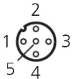
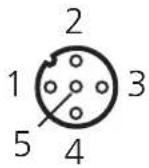
Connect the M12 socket I-1 of the evaluation unit to the corresponding connections of the fail-safe switch or the chain of fail-safe switches (L+, TE, L- and OUT).
I-1
connection fail-safe switches
1: L+
2: TE (clock input)
3: L-
4: OUT (output signal)
5:
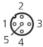
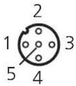
0-3
switching output PNP
1:
2:
3: GND
4: O-3
5:
When the switching output O-3 is used, an FC-E coupling module must be used! Cover the possibly unused socket O-3 with the enclosed protective cap to maintain the specified protection rating.
Parameter setting

Depending on the number of connected fail-safe switch versions the parameters must be set.
Fail-safe switch Even number Odd number
| GI5002 D01=1 D01=0 |
| GM503S D01=1 D01=0 |
| GM504S D01=1 D01=1 |
| GM505S D01=1 D01=1 |
| GI505S D01=1 D01=1 |
| GG505S D01=1 D01=1 |
Addressing
The address has been set to 0 at the factory. Assign a free address between 1 and 31.
Addressing with the addressing unit AC1144
If the mounted and wired module is used with the FC coupling module AC5010 (with addressing socket), it can be addressed via the addressing cable (E70213).

Addressing via the addressing socket is only allowed when the evaluation unit is disconnected.
If it is used with the FC coupling module AC5000 (without addressing socket) the evaluation unit must first be addressed via the addressing unit AC1144 and then mounted onto the lower part.
Infrared addressing
The evaluation unit also offers the option of infrared addressing with the addressing unit AC1144.

The AS-i communication (yellow cable) must be switched off during the infrared addressing. To do so, disconnect the master.
When the ifm AS-i power supplies type SL are used, the communication can be deactivated via a plug on the power supply.
Supply the slaves with voltage via the AS-i power supply. Infrared addressing is carried out via the IR addressing cable E70211.
8. Response times
The response time of the evaluation unit to a safety request is max. 220 ms. Within this period the safety code 0000b (=safe state) is statically transferred.
Calculation of the total response time
For the calculation of the response time of the total system the response times of the other components also have to be added (fail-safe switch, evaluation unit, safety monitor and possibly external relays).
Example:
For the fail-safe switch GM503S the response time to a safety request is < 20 ms and for the safety monitor AC001S < 40 ms. The sum of the individual response times results in the total response time to a safety request of < 280 ms.
The switching times of external relays also have to be added.
9. Fault diagnosis
If after power on the evaluation unit is not enabled, a system fault is assumed. In the easiest case a connected fail-safe switch is not in the operating range.
Location by means of the indicators
Wiring and sensor faults
One way to locate wiring or sensor faults is the indication of the enable signal of the connected inductive fail-safe switches (LED 1, see the figure on page 16).
The connected fail-safe switches can be wired pseudo-serially, i.e. the clock or the enable signal is passed through from the first to the last connected fail-safe switch.
If somewhere in this chain one or several faults occur, the enable signal is interrupted starting from the first detected fault source. The LED 1 yellow provides the information whether all connected fail-safe switches have given the enable signal.
Internal faults
If the evaluation unit detects a fault, the unit changes to the safe state (LED 4 red, see figure on page 16).
A function test of the evaluation unit allows to check whether a hardware error is present or whether the change to the safe state has been caused by external faults.
To do so the evaluation has to be switched off briefly for min. 50 ms (data bit DO0, 1= evaluation OFF, also see page 21).
Voltage supply
If after power on the LED green PWR is not lit, the supply voltage must be checked.

Overload and short circuit of the input supply are signalled to the AS-i master (version 2.1) via the "periphery fault" flag in the status register.
10. Maintenance/duration of use
The evaluation unit is maintenance-free. The maximum duration of use is 10 years.
11. Technical data
G1506S
Active ClassicLine module
AS-i interface to FC/FC-E lower parts
Sockets M12 x 1
AS-i version 2.1
IR addressing possible
category 4 to EN 954-1
For the connection of 1 chain with up to 8 fail-safe switches
| Electrical design M12 1DI 1DO T IP67 | |
| 1 safe input / 1 unsafe output | |
| Operating voltage 26.5...31.6 V DC *) | |
| Current consumption < 250 mA | |
| Enable condition Input signal of the connected fail-safe switches delayed by 0.18 ... 16 ms | |
| Power-on delay time 5 s (Power On), 1 s (normal operation) for enabling respectively without power-on delay time of the connected fail-safe switches. | |
| Response time (also see page 18) < 220 ms | |
| Operating mode Permanent operation | |
| Input fail-safe switches | |
| Sensor supply via AS-i supply | |
| Voltage range 19,2...30 V DC via flat cable | |
| Short-circuit protection pulsed | |
| Reverse polarity / overload protection - / • | |
| Switching output | |
| Galvanically decoupled / short-circuit protection • / • | |
| Current rating 500 mA, PNP switching | |
| External supply to EN 50106 (PELV) via FC-E coupling module | |
| Voltage range | 24 V DC (15...30 V DC) via flat cable |
- = yes
| Function display | ||
| Operation LED green; AS-i/external voltage supply | ||
| Error LED red; AS-i communication or periphery fault,initialisation phase or error in evaluation | ||
| Function LED yellow; switching signal fail-safe switches or chainstate unsafe output | ||
| Characteristic values | ||
| Safety classification Category 4 to EN 954-1 | ||
| AS-i profile S-7.B.E | ||
| I/O configuration 7 [Hex] | ||
| ID code B.E [Hex] | ||
| AS-i certificate 61801 | ||
| EMC EN 50295 | ||
| Operating temperature -25...+55°C | ||
| Relative humidity < 95% | ||
| Height above sea level max. 2000 m | ||
| Protection IP 67 | ||
| Housing materials PBTP (Pocan) | ||
| Housing dimensions 80 x 90 x 46.5 mm (H x W x D) | ||
| Connection contact pins | to FC or FC-E coupling module | |
| Data bitsD0...D3 (bidirectional) | DI0...DI3: transmission of the safety code table(0000 = safe state) | |
| DO0: evaluation switched on/off(0 = evaluation ON) | ||
| DO1: parameter setting depending on the type and number of connected fail-safe switches(see page 17) | ||
| DO2: logic state of the unsafe switching output O-3(0 = O-3 OFF) | ||
| Socket connection | I-1 | O-3 |
| connection fail-safe switches | switching output PNP | |
 |  | |
| 1: L+ | 1: | |
| 2: TE (clock input) | 2: | |
| 3: L- | 3: GND | |
| 4: OUT (output signal) | 4: O-3 | |
| 5: | 5: | |
| Remarks | *) The device shall be supplied from an isolating source and protected by an overcurrent device such that the limited voltage circuit requirements in accordance with UL 508 are met. | |
4. Tests/homologations

Technologie M12 1 E TOR 1 S TOR transistor IP67
Validation of TÜVIT GmbH in cooperation with RWTÜV Systems GmbH
RWTÜV Systems GmbH
Postfach 10 32 61 - 45032 Essen
ZERTIFIKAT
CERTIFICATE
RWTUV
EC-type approval according to annex VI of the EC-Directive 98/37/EC
Manufacturing plant: Waldesch 9, D-88069 Tettnang
(safety related evaluation unit for safety switches with AS-Interface)
UL Underwriters Laboratories Inc.
| Page Bottom | Print-friendly version | Questions? | Previous Page |
| Proximity Switches | |||
| See General Information for Proximity Switches | |||
| IFM ELECTRONIC GMBHTEICHSTRASSE 445127 ESSEN, GERMANY | E174191 | ||
| Photo electric switches, Fibre-optic type, Cat. Nos. OB, OG, OI, OK, OO or OU, followed by F, followed by blank, followed by C, D, F, H or O,followed by BOW, BOA, NKG or KG, followed by up to 11 letter and/or numbers; Reflection type, Cat. Nos. OA, OF, OG, OI, OJ, OS, OT or OUfollowed by B, H, N, R, P or T, followed by blank or L, followed by C, D, F, H or O, followed by BOA, BOW, NKG, PKG, CKG or KOA, followed byup to 11 letters and/or numbers; Through beam type, Cat. Nos. OA, OF, OG, OJ, OS, OT or OU followed by E or S, followed by blank or L, followedby C, D, F, H or O, followed by BOA, BOW, CKG, NKG, KOA, OKG, OOA or PKG, followed by up to 11 letters and/or numbers. | |||
| Photo electric switches, Contour Sensor Types, Cat. No. O2D followed by I or R, followed by O or R, followed by S-G or PKG, followed by up to 11letters and/or numbers. | |||
| Photo electric switches, Accessories, Cat. No. O2D90 followed by 1, 2, 3, 4 or 5; Cat. No. E2D100. | |||
| Proximity switches, Cat. No. IA, IB, IC, ID, IE, IF, IG, II, IL, IM, IN, IS, IT, IW, IY or IZ followed by A, B, C, D, E, K or blank, followed by 2, 3, 4or C, followed by 0.2, 0.8, 001, 1.5, 002, 2.5, 003, 004, 005, 007, 008, 010, 012, 015, 018, 020, 022, 030, 035, 040, 045, 050 or 060, followed by B, D, | |||
NRKH.E174191 - Proximity Switches
Seite 2 von 3
U or blank, followed by A, B, C or F, followed by BOA, BOW, NKG, NOG, PKG, POG, RLA, ROG, ROA, RKA, RKG or SKG, followed by up to 15 letters and/or numbers; Cat. No. KA, KB, KD, KG or KI followed by E or blank, followed by 2 or 3, followed by 008, 010, 015, 020, 050 or 060, followed by A, B or F, followed by BOA, NKG or PKG, followed by up to 15 letters and/or numbers.
Cat. Nos. IN0121, -0122, -0123, -0124, -5353, -5354, -5355, -5356, -5357, -5358, -5359, -5360, -5361, -5362, -5366, -5367, -5374, -5375.
Proximity Switches - Dual Switches, Cat. No. IND3004DBPKG/T2, AC231 followed by 4, 5, 6 or 7.
Cat. Nos. 3MAS-510-TPS, IEB31,5-BPKG, IEB31,5-BPKG/AS, ILB30,8-BPKG, ITB3002-BPKG, IYB31,5-BPKG, IYB31,5-BPKG/AS, IZ93001-BPKG, IZB31,5-BPKG, IEB31,5-BPKG/AS, MK5054, M5055, MK5056; Cat. No. MKN3000-BPKG may be followed by 0.
Cat. Nos. OC-5230, -5231, OCE-CPKG OC5202, OCE-CPKG/US OC5204, OCH-ASI/US OC5227, OCH-CPKG OC5215, OCH-CPKG OC5228, OCH-CPKG/US OC5216, OCH-CPKG/US OC5229, OCK-FCKG/US OC5220, OCP-ASI/US OC5226, OCP-CPKG OC5207, OCP-CPKG/US OC5208, OCS-00KG OC5201, OCS-00KG/US OC5203, OCT-CPKG OC5212, OCT-CPKG/US OC5213, OCV-CPKG OC5218, OCV-CPKG/US OC5219.
Model IIK3008-BPKG/KO/US.
Model I followed by 95 or 90, followed by 009, 011, 012, 001, 002, 003, 004, 005, 006.
Proximity switch, inductive safety switches, Cat. Nos. GIIA-4010-US, GIMC-4030-US, followed by letters and/or numbers.
Proximity switch, inductive safety switch, Accessory, Cat. No. G1500 followed by 1, 2, 4 or 5; Cat. No. G1506S.
Proximity switches, level sensors, Cat. Nos. LK1022, LK1023, LK1024, LK3022, LK3023, LK3024, LK3122, LK3123, LK3124, LK7022, LK7023, LK7024, LK8022, LK8023, LK8024, LK8122, LK8123, LK8124, KN5104, KN5105, KN5106, KN5107, KN5112, KN5116 or KN5118. Proximity switches, magnetic , Cat. No. ME, MF, MG or MS; followed by B, K or blank; followed by 3; followed by 060 or 070; followed by -B; followed by PKG, or NKG; followed by /M; followed by up to 15 letters and/or numbers.
Proximity switches, modular technology, Cat. Nos. IF, IG, II followed by A, B, G or K, followed by 2, 3 or C, followed by 000.8, 001, 002, 3.5, 003, 004, 005, 007, 008, 010, 012, 014, 015, 018, 020, 022, 030, 035, 040, 045, 050 or 060, followed by -A, -B, -F, BA or BB, followed by ASi, RKG, PKG, RKA or SKG, followed by /M, may be followed by up to 15 letters and/or numbers; Cat. No. 0714-473 followed by 000, 001, 003, 004 or 005.
Last Updated on 2005-03-22
- The operating instructions
- Contents
- Safety instructions
- Function and features
- Notes on functions and features
- Configuration requirements
- Hardware-dependent requirements
- Software-dependent requirements
- Tests/approvals
- Items supplied
- Description of the unit
- Operating elements and indicators
- Setup
- Installation
- Electrical connection
- I-1
- 0-3
- Parameter setting
- Addressing
- Addressing with the addressing unit AC1144
- Infrared addressing
- Response times
- Calculation of the total response time
- Example:
- Fault diagnosis
- Location by means of the indicators
- Wiring and sensor faults
- Internal faults
- Voltage supply
- Maintenance/duration of use
- Technical data
- G1506S
- Active ClassicLine module
- Tests/homologations
- ZERTIFIKAT
- CERTIFICATE
- RWTUV
Brand : IFM
Model : G1506S
Category : Industrial control enclosure