
DTE101 - Industrial control enclosure IFM - Free user manual and instructions
Find the device manual for free DTE101 IFM in PDF.
| Product type | RFID industrial control enclosure |
| Brand | IFM |
| Model | DTE101 |
| Dimensions (L x H x D) | 85 mm x 75 mm x 57.5 mm (approx.) |
| Weight | Approx. 200 g |
| Power supply | 18–36 V DC, max. consumption 3 A |
| Interfaces | PROFINET I/O (2 M12 ports), 4 channels for RFID antennas or inputs/outputs |
| Main functions | RFID control, PROFINET communication, configuration via web server, up to 4 antennas |
| Protection rating | IP67 |
| Operating temperature | 0–60 °C (estimated) |
| Mounting | On DIN rail (NS35/15 or NS35/7.5) or panel with 2 M4 screws |
| Electrical connection | M12, tightening torque 1 Nm, shielded cables for PROFINET |
| LED display | LED AUX, SF, BF, IO1–IO4: power, link status, faults |
| Factory settings | IP 192.168.0.79, gateway 192.168.0.100, subnet mask 255.255.255.0 |
| Configuration | Via built-in web server (HTTP) or PROFINET controller |
| Maintenance and cleaning | Clean with a dry cloth; do not open the device |
| Safety | Installation by qualified electrician; comply with SELV/PELV standards |
| Spare parts and repairability | No spare parts available; return in case of defect |
| General information | Complete user manual and instructions available at www.ifm.com |
Frequently Asked Questions - DTE101 IFM
User questions about DTE101 IFM
0 question about this device. Answer the ones you know or ask your own.
Ask a new question about this device
Download the instructions for your Industrial control enclosure in PDF format for free! Find your manual DTE101 - IFM and take your electronic device back in hand. On this page are published all the documents necessary for the use of your device. DTE101 by IFM.
USER MANUAL DTE101 IFM
Operating instructions
RFID evaluation unit
natural_image
Technical line drawing of a mechanical component with multiple circular features and mounting brackets (no text or symbols)Inhalt
5.2 Einbaulage
natural_image
Diagram of a vehicle under load with a numbered arrow and gear mechanism (no text or symbols)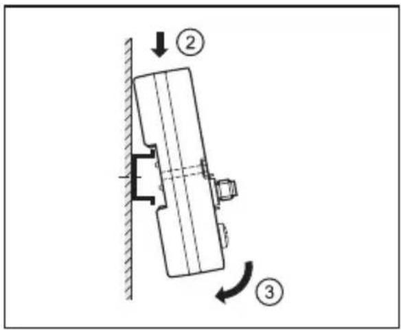
natural_image
Technical line drawing of a mechanical assembly with a screw and pin, no text or symbols present
6.3 Prozessanschlüsse IO-1 ... IO-4
natural_image
Technical line drawing of a mechanical or electrical component with mounting bracket and wiring (no text or symbols)6.4.2 Montageplatte
natural_image
Top-down schematic of an electronic device with multiple ports and a light bulb at the bottom (no text or symbols)1 Preliminary note ....4
1.1 Notes on this document 4
1.2 Symbols used ....4
2 Safety instructions ....4
2.1 General 4
2.2 Installation and connection ....4
2.3 Tampering with the device ....5
3 Functions and features ....5
3.1 Configuration via Ethernet interface ....5
3.2 RFID antennas 6
4 Function....6
5 Installation....6
5.1 Installation distance 6
5.2 Installation orientation 7
5.3 Mounting options ....7
5.3.1 Mounting on DIN rail 7
5.3.2 Removal 8
5.3.3 Mounting plate 8
6 Electrical connection 9
6.1 AUX voltage supply 9
6.2 Field bus connection PROFINET IO Port 1 / Port 2 ......10
6.2.1 Factory setting of the Ethernet parameters 10
6.3 Process connections IO-1 ... IO-4 11
6.4 Functional earth connection....12
6.4.1 Mounting on DIN rail 12
6.4.2 Mounting plate 12
7 Operating and display elements ....13
7.1 Reset to factory settings ....13
7.2 LED indicators ....13
7.2.1 LED AUX 13
7.2.2 LED PROFINET Port 1 / Port 2 ......14
7.2.3 LED SF 14
7.2.4 LED BF 15
2
7.2.5 LEDs IO1 ... IO4 ....15
7.2.6 Special device- LED indications .....17
8 Technical data ....17
8.1 Data sheets ...... 17
8.2 Device manual ....17
9 Maintenance, repair and disposal ....18
10 Approvals/standards ....18
11 Scale drawing 18
UK
Licences and trademarks
Microsoft® und Internet Explorer® are registered trademarks of Microsoft Corporation. All trademarks and company names are subject to the copyright of the respective companies.
1 Preliminary note
1.1 Notes on this document
This document applies to the RFID evaluation unit DTE101.
It is part of the device and contains information about the correct handling of the product.
This document is intended for qualified electricians. These specialists are people who are qualified by their training and their experience to see and to avoid possible hazards that may be caused during operation of the device.
Read this document before use to familiarise yourself with operating conditions, installation and operation. Keep this document during the entire duration of use of the device.
1.2 Symbols used
▶ Instructions
Reaction, result
[...] Designation of pushbuttons, buttons or indications
→ Cross-reference

Important note
Non-compliance can result in malfunction or interference.

Information
Supplementary note
2 Safety instructions
2.1 General
▶ Observe these operating instructions.
▶ Adhere to the warning notes on the product.
Non-observance of the instructions, operation which is not in accordance with use as prescribed below, wrong installation or incorrect handling can affect the safety of operators and machinery.
2.2 Installation and connection
The device must only be installed, connected and put into operation by a qualified electrician as the safe function of the device and machinery is only guaranteed when installation is correctly carried out. The installation and connection must
comply with the applicable national and international standards. Responsibility lies with the person installing the device.

This is a class A product. The device may cause radio interference in domestic areas. In this case it can be necessary for the user to take appropriate measures.
2.3 Tampering with the device
Tampering with the device is not allowed and will lead to an exclusion of liability and warranty. Tampering with the device can affect the safety of operators and machinery.
▶ Do not open the device.
▶ Do not insert any objects into the device.
▶ Prevent metal foreign bodies from penetrating.
UK
3 Functions and features
The RFID evaluation unit DTE101 integrates a PROFINET IO interface and 4 channels for the connection of field devices. Each channel can be used either for the connection of an RFID antenna or as input/output to IEC 61131.
The device
- controls the data exchange to the RFID antennas or the sensor/actuator level.
- communicates with the higher-level control level via PROFINET IO.
- allows device configuration via a web server.
Application examples:
• Material flow control in production lines
- Warehouse management by the automatic detection of stored products
- Tank management, order picking or product tracking
3.1 Configuration via Ethernet interface
• 10 Mbps and 100 Mbps
• TCP / IP - Transport Control Protocol / Internet Protocol
• UDP - User Datagram Protocol
• IT functionality: HTTP server
- M12, twisted pair
3.2 RFID antennas
The device supports up to four RFID read/write heads of type ANT41x / ANT51x from ifm electronic gmbh.
You can find information about the matching read/write heads on our website at:
www.ifm.com → data sheet search → ANT41 or ANT51
4 Function
You can find detailed information about the function of the system in the device manual at:
www.ifm.com → data sheet search → DTE101 → Operating instructions
5 Installation
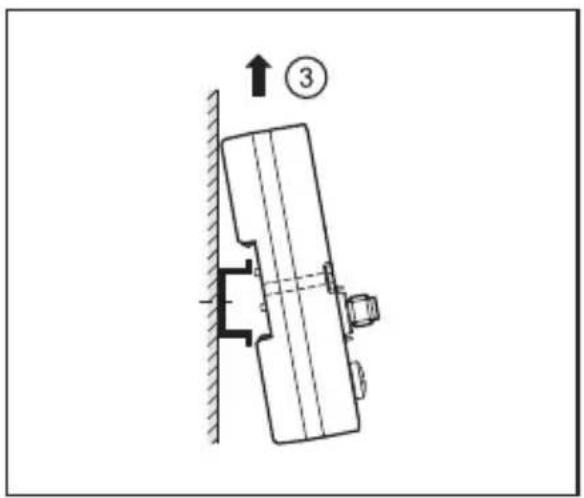
5.1 Installation distance
Due to the internal heating of the device a minimum distance to other objects of 10 mm is to be taken into account during installation.
5.2 Installation orientation
The installation orientation can be freely selected.

In a wet environment upside-down mounting is not permitted.
5.3 Mounting options
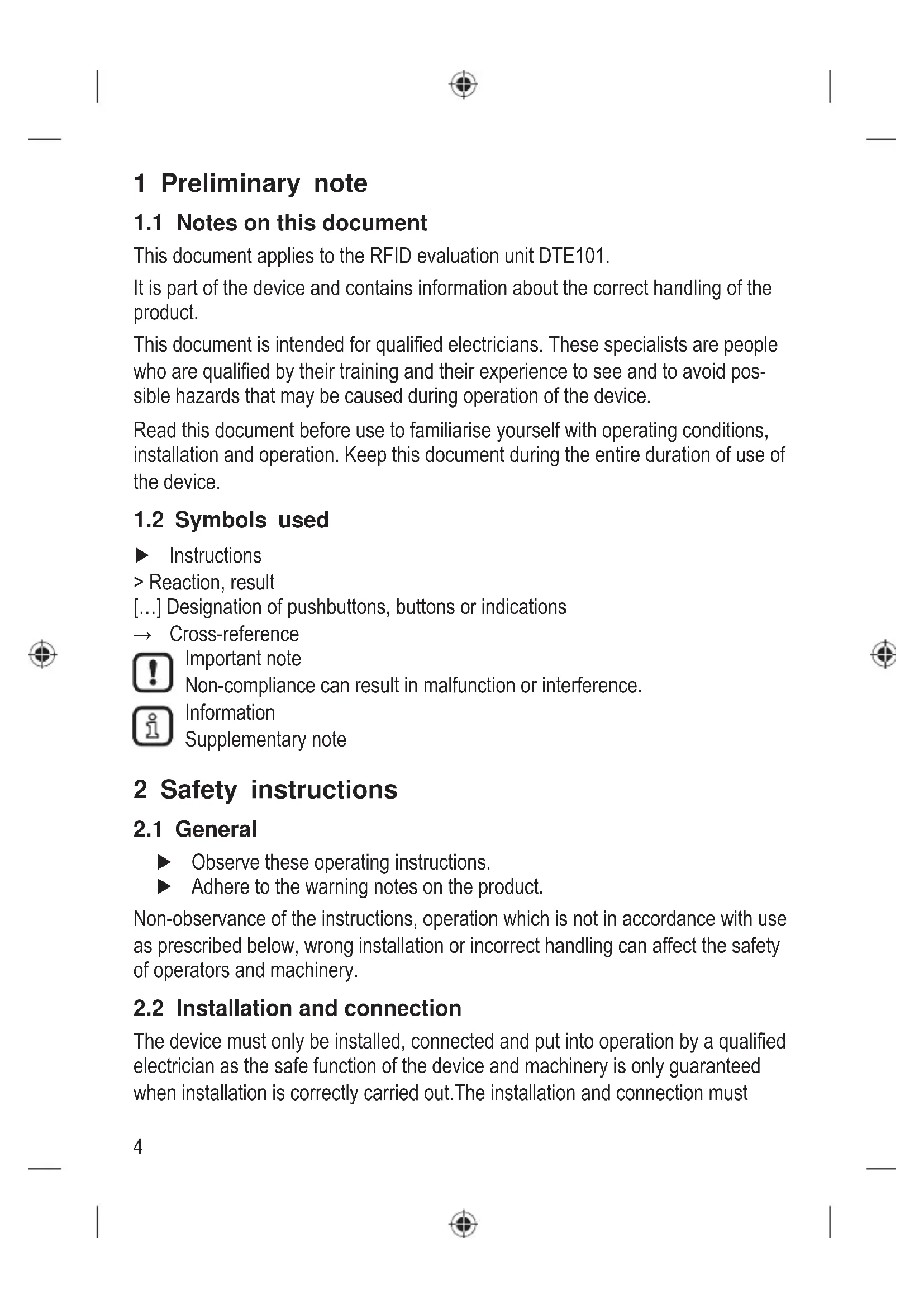
5.3.1 Mounting on DIN rail
The device can be installed on a DIN rail of type NS35/15 or NS35/7.5.
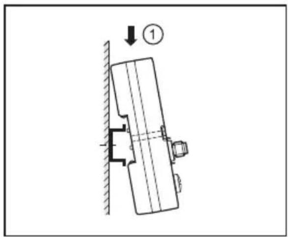
natural_image
Technical diagram of a mechanical assembly with a downward force arrow and numbered component (no text or symbols)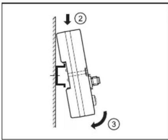
UK
- Angle the device and place the fixing clamp onto the upper edge of the DIN rail.
- Press device down.
- Simultaneously rotate the device in the direction of the DIN rail.
5.3.2 Removal
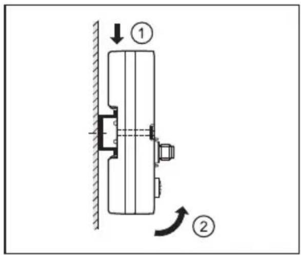
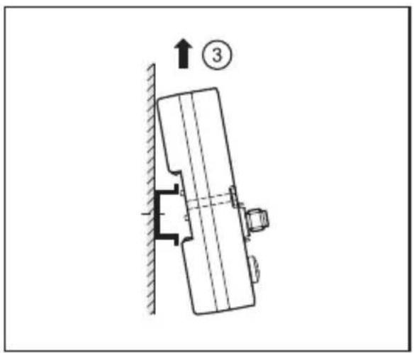
- Press device down.
- Simultaneously rotate the device away from the DIN rail.
- Remove the device from the top.
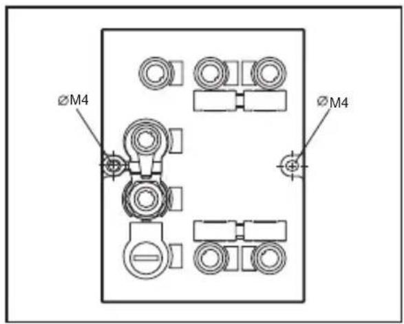
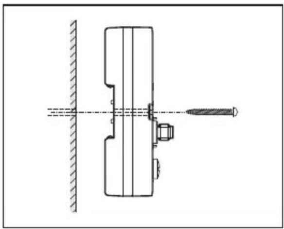
5.3.3 Mounting plate
The device can be fixed to a mounting plate using 2 screws (M4 x 35 or longer).
natural_image
Technical line drawing of a mechanical assembly with a screw and pin, no text or symbols present
This installation mode is recommended for vibration and shock requirements.
6 Electrical connection

The device must be connected by a qualified electrician.
▶ Disconnect power before connecting the device.
▶ Observe the national and international regulations for the installation of electrical equipment.
▶ Ensure voltage supply to EN 50178, SELV, PELV.
▶ Connect the device according to the indicated pin connection.
▶ A total current consumption of the device of 3 A must not be exceeded.
Please note the following points to ensure protection rating IP 67:
▶ Cover the unused sockets with protective caps.
▶ Tighten all protective caps and connectors with a tightening torque of 1 Nm.
You will find matching accessories at www.ifm.com
| Accessories ifm article number | |
| Protective cap E73004 | |
| Torque wrench E70390 |
UK
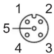
6.1 AUX voltage supply
▶ Connect the device to the voltage supply using an M12 connection cable.
 | Pin Connection | |
| 1 24 V DC | ||
| 2 Not used | ||
| 3 | 0 V | |
| 4 Not used | ||
| 5 Not used | ||
You can find matching connection cables at:
www.ifm.com → data sheet search → DTE101 → Accessories
6.2 Field bus connection PROFINET IO Port 1 / Port 2
- Connect the device to a PROFINET IO controller using a suitable M12 Ethernet connection cable.
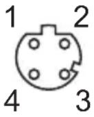 Note: screened connection cable required Note: screened connection cable required | Pin Connection | |
| 1 TD+ | ||
| 2 RD+ | ||
| 3 TD- | ||
| 4 RD- | ||
6.2.1 Factory setting of the Ethernet parameters
The following values are preset on delivery of the device:
| Parameters Factory setting | |
| IP address 192.168.0.79 | |
| Gateway address 192.168.0.100 | |
| Subnet mask 255.255.255.0 | |
| Auto-negotiation on | |
| DHCP off |
The settings can be changed via the unit's webserver or via the PROFINET IO controller.
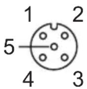
6.3 Process connections IO-1 ... IO-4
Each process connection can be used as input/output to IEC 61131 or for connection of an RFID read/write head. The connections are set via the hardware configuration of the PROFINET IO controller.
| Pin Connection | |
| 1 | L+ |
| 2 Switching input (I/Q) | |
| 3 | L- |
| 4 Switching output (C/Qo) or input (C/Qi) | |
| 5 Not used | |
UK

The evaluation unit has to be disconnected before field units are connected.

Please note that the total current consumption of the device must not exceed the value of 3 A.
You can find detailed information about the available operating modes in the device manual at:
www.ifm.com → data sheet search → DTE101 → Operating instructions
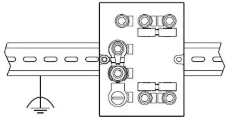
6.4 Functional earth connection.

To ensure trouble-free operation the device must be connected to an earth potential free from external voltage.
6.4.1 Mounting on DIN rail
The connection is made automatically via the DIN rail. Note that the DIN rail must be connected with the earth potential.
natural_image
Technical line drawing of a mechanical or electrical component with mounting bracket and wiring (no text or symbols)6.4.2 Mounting plate
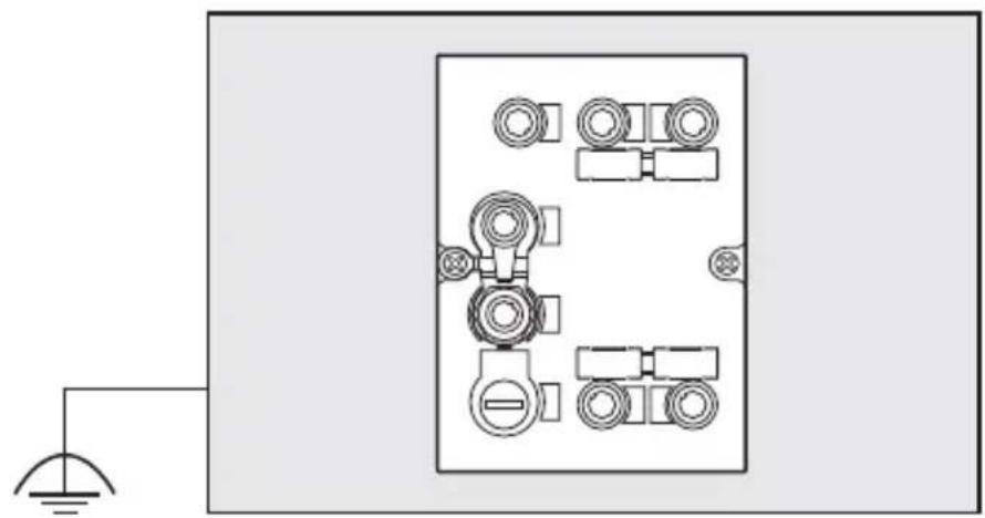
When the device is fixed on a mounting plate, connection is made via the left fixing screw. Note that the plate must be connected with the earth potential.
natural_image
Top-down schematic of an electrical enclosure with multiple circular components and a light bulb at the base (no text or symbols)7 Operating and display elements
7.1 Reset to factory settings
The Ethernet parameters can be reset to the factory settings. Take the following steps:
▶ Remove all cable connections from the device.
▶ Insert an electrically conductive bridge between pin 1 and pin 3 on the process connection IO-3.
▶ Connect device with the voltage supply and wait until the yellow LED indication on AUX and IO-3 flashes at approx. 8 Hz.
▶ Disconnect the device from the voltage supply and connect it again.
The settings are reset.
7.2 LED indicators
The device indicates the current status of the interface via the status LEDs.
7.2.1 LED AUX
| LED green LED yellow Status Note | |||
| Off Off No voltage supply U | _AUX < 5 V | ||
| On | Flashes at 2 Hz | Voltage supply too low | 5 V ≤ U_AUX ≤ 18 V |
| On Off | Voltage supply OK | 18 V ≤ U | _AUX ≤ 36 V |
UK
7.2.2 LED PROFINET Port 1 / Port 2
| LED green | LED yellow | Status Note | |
| Off Off | No connection to another Ethernet counterpart | Link status "no link"" | |
| On Off | Connection to Ethernet counterpart exits, no data exchange | Link status "link", "no traffic" | |
| On | Flashes sporadically | Connection to Ethernet counterpart exists, data exchange running | Link status "link", "traffic" |
7.2.3 LED SF
| LED red LED green Status Note | |||
| off off no | voltage supply | check voltage supply | |
| off flashes | "Node flash test", initiated by PROFINET IO controller | - | |
| off on normal operation - | |||
| flashes off | error on channel level | - overload- temperature- internal fault | |
| on off error on device level | - undervoltage- temperature | ||
| flashes flashes self-test | starting phase of the device | ||
7.2.4 LED BF
| LED red LED green Status Note | |||
| off off no voltage supply | check the voltage supply | ||
| off flashes | PROFINET IO controller is in STOP mode | - | |
| off on | PROFINET IO controller is in RUN mode | - | |
| flashes off | connection to the PROFINET IO controller is established, no valid configuration | check configuration | |
| on off | no connection to PROFINET IO controller | check connection | |
| flashes flashes self-test | starting phase of the device | ||
UK
7.2.5 LEDs IO1 ... IO4
The LED indications of the process connections differ with each connection configuration.
Use as input to IEC 61131
| LED green LED yellow Status Note | |||
| Off | Off | Interface deactivated | Interface in PROFINET IO controller not configured |
| On | Off | Interface activated, input on L level (0 V) | - |
| On | On | Interface activated, input on H level (24 V) | - |
| Flashes at 8 Hz | Flashes at 8 Hz | Overload or short circuit | - |
Use as output to IEC 61131
| LED green L | LED yellow Status Note | ||
| Off Off | Interface deactivated | Interface in PROFINET IO controller not configured | |
| On Off | Interface activated, output L-active (0 V) | - | |
| On On | Interface activated, output H-active (24 V) | - | |
| Flashes at 8 Hz | Flashes at 8 Hz | Overload or short circuit - | |
Use with RFID read/write heads
| LED green LED yellow Status Note | |||
| Off Off Interface deactivated | Interface in PROFINET IO controller not configured | ||
| Flashes at 2 Hz | Off | Interface activated, antenna off | - |
| On Off | Interface activated, tag not in the field | - | |
| On On | Interface activated, tag in the field | - | |
| Flashes at 8 Hz | Flashes at 8 Hz | Overload, short-circuit or communication error | - |
7.2.6 Special device- LED indications
| LED Status Note | ||
| Green AUX LED onYellow AUX LED flashes at 8 HzYellow IO1...IO4 LEDs flash at 8 Hz | Device is in the service mode "emergency system started". | A firmware update is necessary and can be executed via the web server. |
| Green AUX LED onYellow AUX LED flashes at 8 HzGreen IO1...IO4 LEDs flash at 8 HzYellow IO1...IO4 LEDs flash at 8 Hz | Major error, device has to be returned. | Hardware fault or permanent data in the device are corrupt. |
| Green AUX LED onYellow AUX LED Flashes at 8 HzYellow IO3 LED flashes at 8 Hz | Reset to factory settings - |
8 Technical data
8.1 Data sheets
Data sheets can be found at:
www.ifm.com → data sheet search → DTE101
8.2 Device manual
The device manual can be found at:
www.ifm.com → data sheet search → DTE101 → operating instructions

9 Maintenance, repair and disposal
▶ Dispose of the device in accordance with the national environmental regulations.
10 Approvals/standards
The EC declaration of conformity and approvals can be found at:
www.ifm.com → data sheet search → DTE101 → Approvals
11 Scale drawing

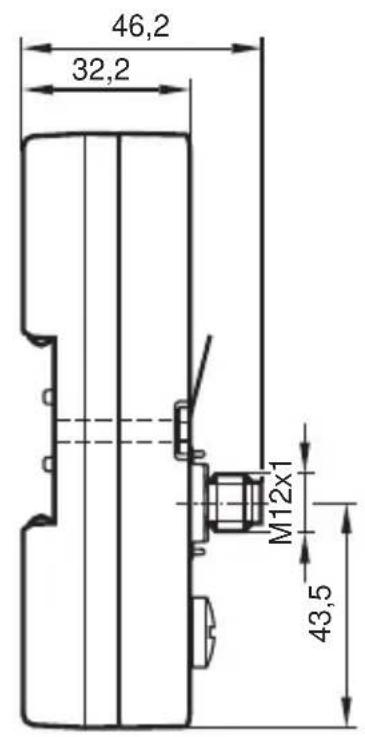
UK


Contenu
natural_image
Technical diagram of a mechanical assembly with a downward force arrow and numbered component (no text or symbols)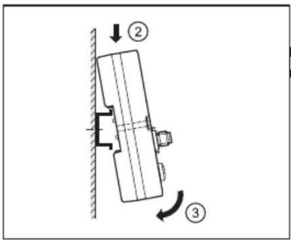
FR

natural_image
Technical diagram of a mechanical assembly with a numbered component (3) and directional arrow, no readable text or symbols present.natural_image
Technical line drawing of a mechanical assembly with a pin and shaft, no text or symbols present
6.3 Prises de raccordement IO-1 ... IO-4
natural_image
Technical line drawing of a mechanical or electrical component with mounting bracket and wiring (no text or symbols)natural_image
Top-down schematic of an electronic device with multiple circular components and a light bulb at the base (no text or symbols)
- Inhalt
- Einbaulage
- Prozessanschlüsse IO-1 ... IO-4
- Montageplatte
- Preliminary note
- Notes on this document
- Symbols used
- Safety instructions
- General
- Installation and connection
- Tampering with the device
- Functions and features
- Configuration via Ethernet interface
- RFID antennas
- Function
- Installation
- Installation distance
- Installation orientation
- Mounting options
- Mounting on DIN rail
- Removal
- Mounting plate
- Electrical connection
- AUX voltage supply
- Field bus connection PROFINET IO Port 1 / Port 2
- Factory setting of the Ethernet parameters
- Process connections IO-1 ... IO-4
- Functional earth connection.
- Mounting on DIN rail
- Mounting plate
- Operating and display elements
- Reset to factory settings
- LED indicators
- LED AUX
- LED BF
- LEDs IO1 ... IO4
- Use as input to IEC 61131
- Technical data
- Data sheets
- Device manual
- Maintenance, repair and disposal
- Approvals/standards
- Scale drawing
- Contenu
- Prises de raccordement IO-1 ... IO-4
Brand : IFM
Model : DTE101
Category : Industrial control enclosure