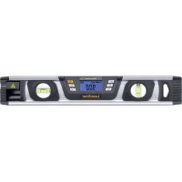
DigiLevelLaser G40 - Laser level Laserliner - Free user manual and instructions
Find the device manual for free DigiLevelLaser G40 Laserliner in PDF.



| Product Type | Digital green line laser level |
| Brand | Laserliner |
| Model | DigiLevelLaser G40 |
| Laser technology | Class 2 green laser, < 1 mW, 515 nm |
| Electronic measurement accuracy | ±0.1° (0° to 1° and 89° to 90°), ±0.2° (1° to 89°) |
| Bubble accuracy | ±0.5 mm/m |
| Angle measurement range | 360° (continuous measurement) |
| Display | Digital with backlight |
| Measurement units | °, %, mm/m |
| Main functions | Angle measurement, HOLD function, reference value, calibration, beep, backlight |
| Power supply | 2 AAA/LR03 batteries (1.5 V) |
| Dimensions (L x H x D) | 400 x 66 x 30 mm |
| Weight (including batteries) | 566 g |
| Integrated magnets | Yes |
| Operating temperature | 0 °C to 40 °C |
| Storage temperature | -10 °C to 60 °C |
| Maximum humidity | 80 % RH, non-condensing |
| Max. working altitude | 2000 m |
| Automatic shut-off | After 3 minutes of inactivity |
| Cleaning | Slightly damp cloth, no solvents |
| Storage | Dry and clean place, remove batteries |
| Laser safety | Class 2, do not look into the beam |
Frequently Asked Questions - DigiLevelLaser G40 Laserliner
User questions about DigiLevelLaser G40 Laserliner
0 question about this device. Answer the ones you know or ask your own.
Ask a new question about this device
Download the instructions for your Laser level in PDF format for free! Find your manual DigiLevelLaser G40 - Laserliner and take your electronic device back in hand. On this page are published all the documents necessary for the use of your device. DigiLevelLaser G40 by Laserliner.
USER MANUAL DigiLevelLaser G40 Laserliner
Laserliner

natural_image
Pure electrical circuit lines without any symbolsLaser an Laser aus
Sicherheitshinweise
natural_image
Pure electrical circuit lines without any symbols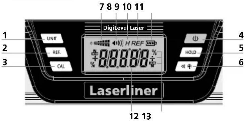
natural_image
Cross-sectional diagram of a mechanical component with internal channels and mounting holes (no text or labels)natural_image
Pure technical line drawing of a mechanical component or bracket (no text or symbols)Completely read through the operating instructions, the „Warranty and Additional Information“ booklet as well as the latest information under the internet link at the end of these instructions. Follow the instructions they contain. This document must be kept in a safe place and passed on together with the device.
Function / application
Digital electronic spirit level with green laser technology
– Wall line laser to optically extend the measurement area
– Horizontal and vertical angle display
– The slope memory allows angles to be easily transferred
General safety instructions
- The device must only be used in accordance with its intended purpose and within the scope of the specifications.
- The measuring tools and accessories are not toys. Keep out of reach of children.
- Modifications or changes to the device are not permitted, this will otherwise invalidate the approval and safety specifications.
- Do not expose the device to mechanical stress, extreme temperatures, moisture or significant vibration.
- The device must no longer be used if one or more of its functions fail or the battery charge is weak.
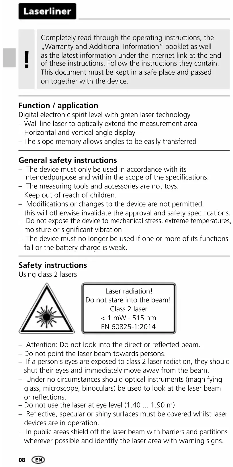
Safety instructions
Using class 2 lasers

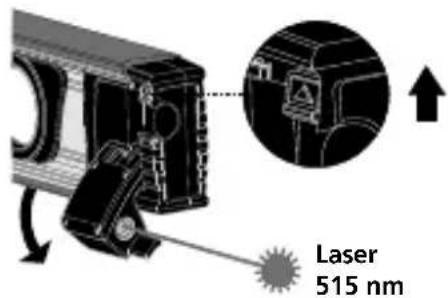
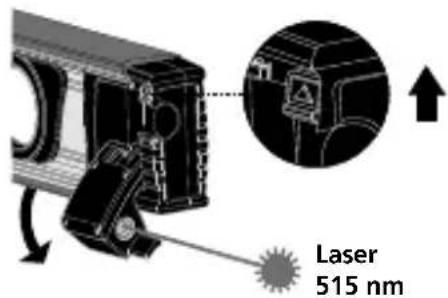
Laser radiation! Do not stare into the beam! Class 2 laser < 1 mW · 515 nm EN 60825-1:2014
- Attention: Do not look into the direct or reflected beam.
- Do not point the laser beam towards persons.
- If a person's eyes are exposed to class 2 laser radiation, they should shut their eyes and immediately move away from the beam.
- Under no circumstances should optical instruments (magnifying glass, microscope, binoculars) be used to look at the laser beam or reflections.
- Do not use the laser at eye level (1.40 ... 1.90 m)
- Reflective, specular or shiny surfaces must be covered whilst laser devices are in operation.
- In public areas shield off the laser beam with barriers and partitions wherever possible and identify the laser area with warning signs.
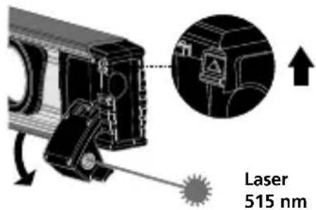
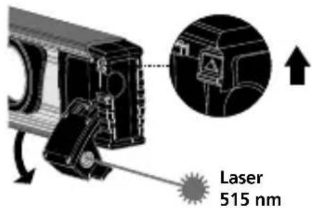
Laser outlet
natural_image
Pure electrical circuit lines without any symbolsLaser on Laser off
Safety instructions
Dealing with electromagnetic radiation
- The measuring device complies with electromagnetic compatibility regulations and limit values in accordance with EMC-Directive 2014/30/EU.
- Local operating restrictions – for example, in hospitals, aircraft, petrol stations or in the vicinity of people with pacemakers – may apply. Electronic devices can potentially cause hazards or interference or be subject to hazards or interference.
Green laser technology

Laser modules in DLD design stand for high line quality as well as a clean and clear and therefore
easily visible line image. Unlike previous generations they are more temperature-stable and energy efficient.
Furthermore, the human eye has a higher sensitivity to the wave range of the green laser than the red laser, for example. This makes the green laser diode appear much brighter than the red one.
Green lasers, especially in the DLD design, thus offer advantages with regards to how visible the laser line is under unfavourable conditions.

Approx. 6 times brighter than a typical red laser with 630 - 660 nm
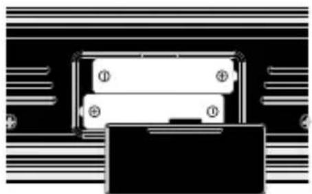
1 Inserting batteries
Open the battery compartment and insert batteries according to the symbols. Be sure to pay attention to polarity.
natural_image
Pure electrical circuit lines without any symbols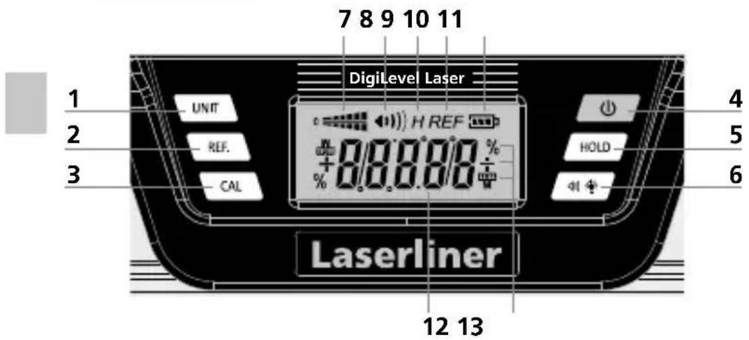
1 Change units of measure
2 Angle reference value setting
3 Calibration
4 ON/OFF button
5 Hold function
6 Acoustic signal generator / Backlighting ON/OFF
7 Slope direction
8 Acoustic signal generator active
9 HOLD: current measured value is held
10 Angle reference set
11 Battery charge
12 Slope angle
13 Units of measure
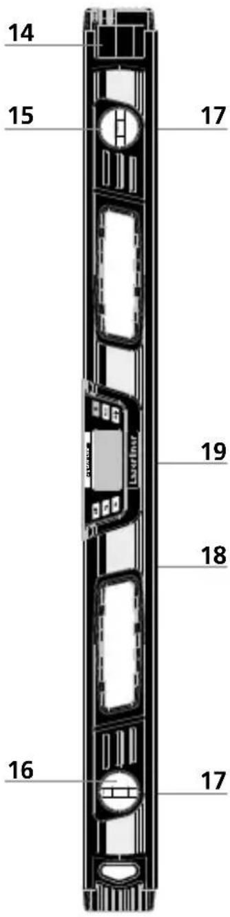
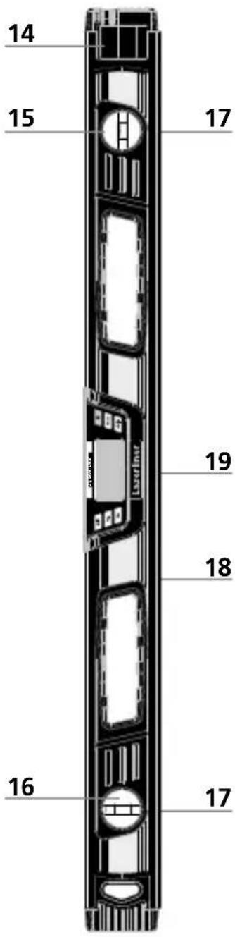
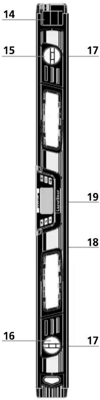
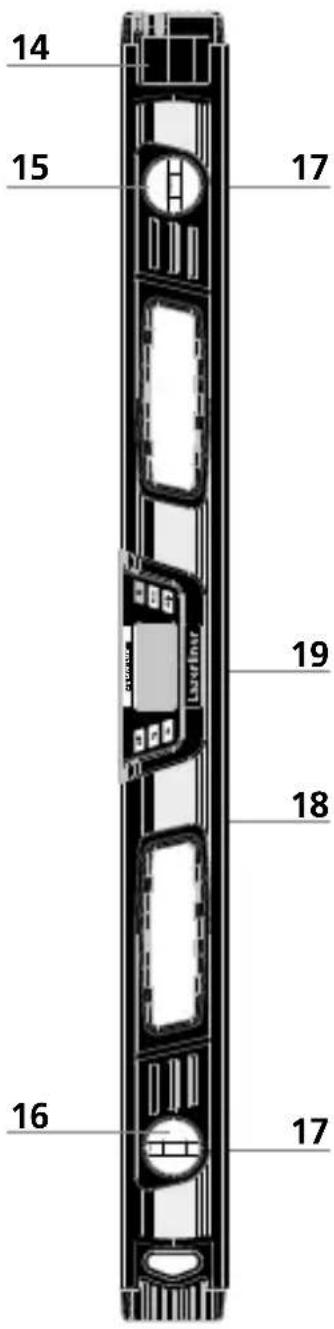
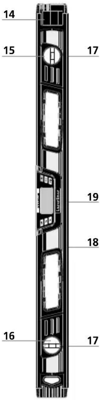
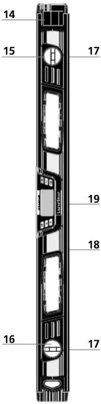
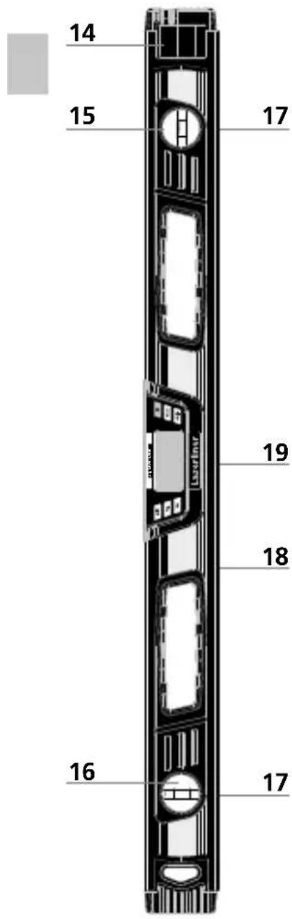
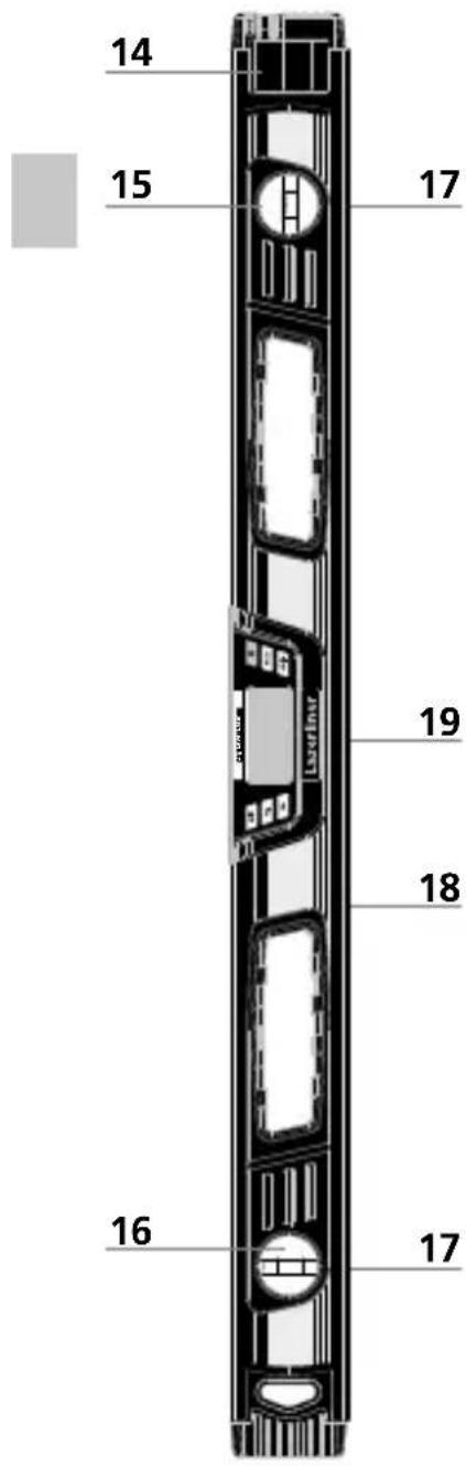
14 Line laser
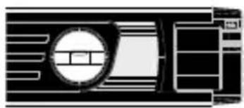
15 Horizontal vial
16 Vertical vial
17 Magnets
18 Measuring surface
19 Battery compartment (Rear)
2 Switching on and measuring

Make sure that the reference function is deactivated before measuring.
The DigiLevel Laser G40 / G80 can measure angles continuously to 360°.
- Switch the DigiLevel Plus on using the on/off switch (4).
- The slope angle is shown in the display (8). If slopes are measured overhead, the direction of display adjusts automatically.
- The current slope direction is also shown by the symbol (7).
3 Selection of unit of measurement
Button (5) allows the desired unit of measurement to be selected (° degrees, %, mm/m).
4 Calibration
- Place the unit with its measuring edge (18) down on a straight surface and mark the positions of the unit's ends on the underlying surface (see Fig. below). Switch the unit on (4) and press the REF button (2) until CAL 1 starts blinking. Shortly thereafter an acoustic signal will sound and CAL 2 will appear in the display.

natural_image
Pure electrical circuit lines without any symbols- Now turn the unit around horizontally (end-for-end) by 180^ such that its ends are positioned opposite where they previously were but again exactly at the underlying surface marks (reverse measurement). Again press the REF button (2) until CAL 2 blinks. The subsequent acoustic signal concludes the process.

natural_image
Pure electrical circuit lines without any symbols
The unit is properly calibrated when it displays the same measurement value, i.e. the underlying surface's deviation from absolute level, in both positions (0° and 180°).
Laserliner
5 Changing the angle reference value
With button (2), it is possible to transfer angles elsewhere. To do so, set the device to the desired slope and press button (2). The display then changes to „0.0°“, „REF“ flashes on the display and the required reference angle is set. The slope can now be transferred to other objects. Press button (2) again to deactivate the angle reference.

The angle reference is not deactivated by switching off the device.
6 °C / °F / measured value
The ambient temperature is shown in °C and °F by briefly pressing the CAL button (3). Press again to switch back to the measured value.
7 HOLD
Press the HOLD button (5) to hold the current measured value on the display.
8 Acoustic signal
The acoustic signal can be switched on or off with button (6). When the angle of slope stands at 0^ , 45^ , 90^ or the most recently stored value, this is indicated by an acoustic signal.

When working with a changed angle reference value, the acoustic signal is activated on reaching the new reference value ( 0^ , 45^ , 90^ display).
9 Backlighting
The backlighting is switched ON/OFF by pressing and holding button (6).
Auto Off function
In order to preserve the batteries, the measuring device switches off automatically if it is left idle for 3 minutes.
Information on maintenance and care
Clean all components with a damp cloth and do not use cleaning agents, scouring agents and solvents. Remove the battery(ies) before storing for longer periods. Store the device in a clean and dry place.
Danger – powerful magnetic fields
Powerful magnetic fields can adversely affect persons with active medical implants (e.g. pacemaker) as well as electromechanical devices (e.g. magnetic cards, mechanical clocks, precision mechanics, hard disks).
With regard to the effect of powerful magnetic fields on persons, the applicable national stipulations and regulations must be complied with such as BGV B11 §14 „electromagnetic fields” (occupational health and safety - electromagnetic fields) in the Federal Republic of Germany.
To avoid interference/disruption, always keep the implant or device a safe distance of at least 30 cm away from the magnet.
Technical data
| Electronic measuring precision | ± 0,1° at 0° ... 1° ± 0,1° at 89° ... 90° ± 0,2° at 1° ... 89° |
| Display accuracy 1 decimal place | |
| Vial | ± 0,5 mm/m |
| Laser class 2 / < 1 mW | |
| Laser wavelength | 515 nm |
| Operating conditions | 0 ... 40°C, max. humidity 80% rH, no condensation, max. working altitude 2000 m above sea level |
| Storage conditions | -10°C ... 60°C, max. humidity 80% rH |
| Power supply | 2 x 1.5V (type AAA/LR03) |
| Dimensions (W x H x D) G40 400 x 66 x 30 mm | |
| Dimensions (W x H x D) G80 | 800 x 66 x 30 mm |
| Weight (incl. batteries) G40 / G80 | 566 g / 966 g |
Subject to technical change without notice. 18W44
EU directives and disposal
This device complies with all necessary standards for the free movement of goods within the EU.
This product is an electric device and must be collected separately for disposal according to the European Directive on waste electrical and electronic equipment.
Further safety and supplementary notices at: http://laserliner.com/info?an=AHH

Laserliner

natural_image
Pure electrical circuit lines without any symbolsLaser aanLaser uit
natural_image
Pure electrical circuit lines without any symbols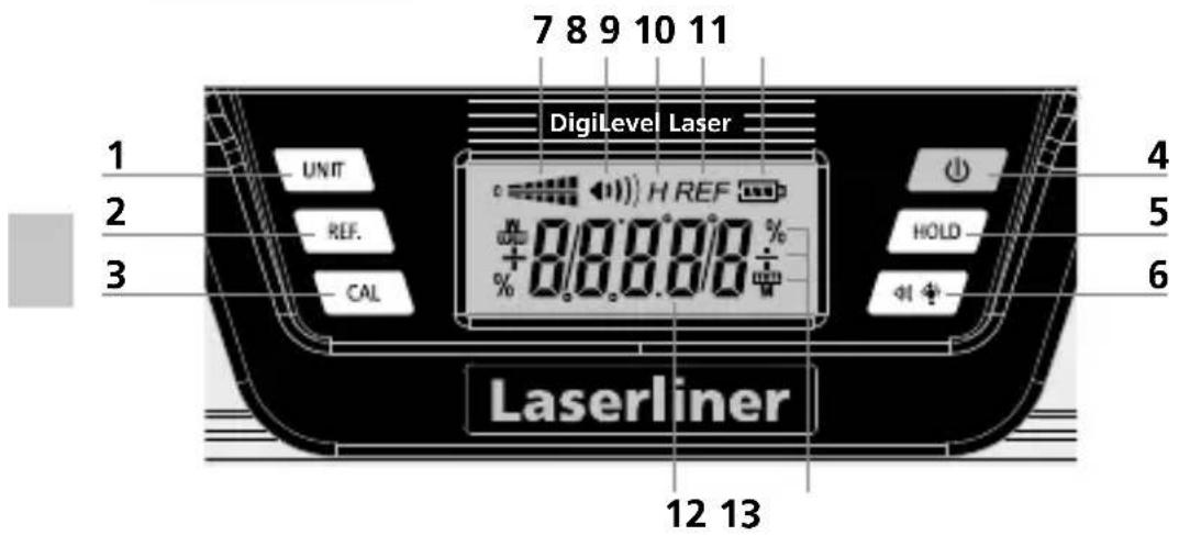
natural_image
Cross-sectional diagram of a mechanical or electrical component with no visible text or symbolsnatural_image
Pure mechanical component diagram without any text, numbers, or symbolsnatural_image
Pure electrical circuit lines without any symbols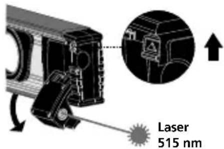
natural_image
Pure electrical circuit lines without any symbols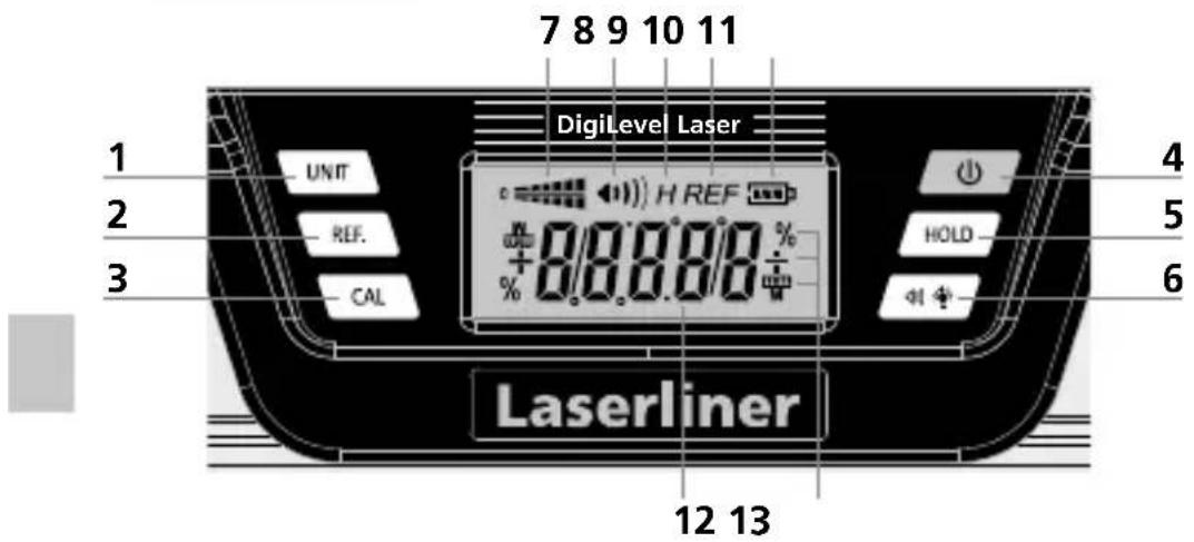
natural_image
Pure electrical circuit lines without any symbols
natural_image
Pure electrical circuit lines without any symbols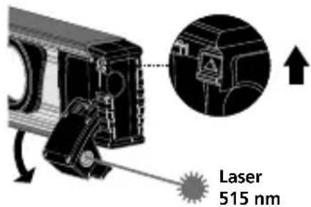
natural_image
Pure electrical circuit lines without any symbols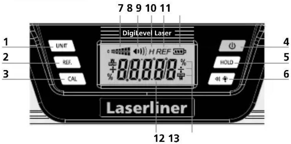
natural_image
Technical line drawing of a mechanical component with no visible text or symbolsnatural_image
Pure mechanical component diagram without any text, numbers, or symbols
natural_image
Pure electrical circuit lines without any symbolsnatural_image
Pure electrical circuit lines without any symbols
natural_image
Pure technical line drawing of a mechanical component without any text, numbers, or symbolsnatural_image
Pure electrical circuit lines without any symbols
natural_image
Pure electrical circuit lines without any symbolsLaser on Laser off
natural_image
Pure electrical circuit lines without any symbols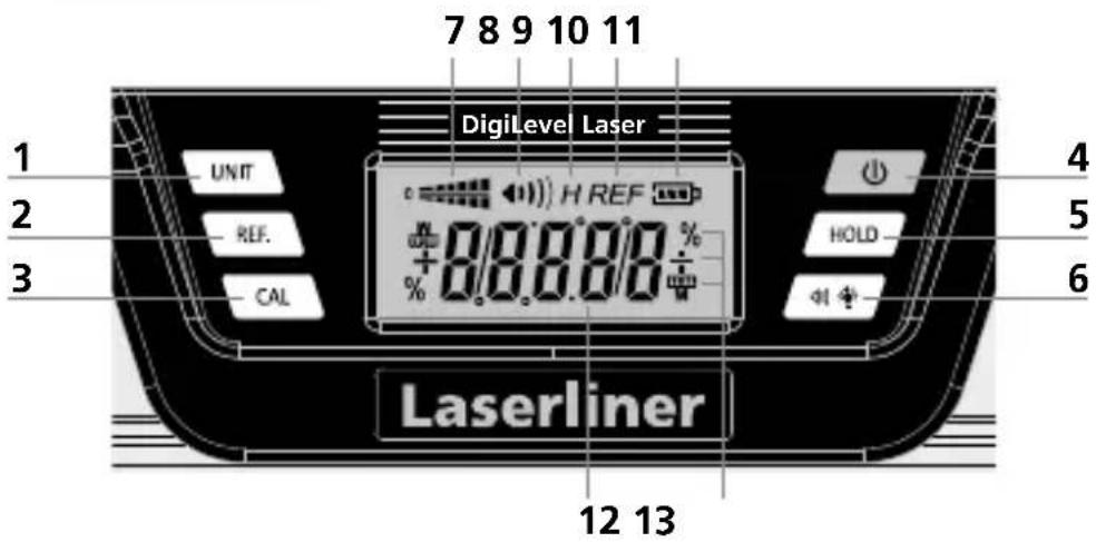
natural_image
Technical line drawing of a mechanical component with multiple ports and mounting holes (no text or symbols)natural_image
Technical line drawing of a mechanical component with internal channels and mounting holes (no text or symbols)natural_image
Pure electrical circuit lines without any symbolsnatural_image
Pure electrical circuit lines without any symbols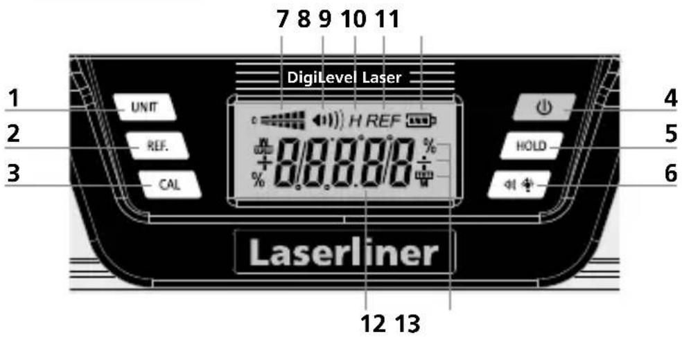
natural_image
Technical line drawing of a mechanical component with multiple ports and mounting holes (no text or symbols)natural_image
Pure technical line drawing of a mechanical component with no text or symbolsnatural_image
Interior of an art gallery with wooden flooring, framed artworks on walls, and a large wall display (no visible text or symbols)SERVICE


Umarex GmbH & Co. KG
- Laserliner -
- Laserliner
- Sicherheitshinweise
- Function / application
- General safety instructions
- Safety instructions
- Laser outlet
- Green laser technology
- Inserting batteries
- Switching on and measuring
- Selection of unit of measurement
- Calibration
- Changing the angle reference value
- °C / °F / measured value
- HOLD
- Acoustic signal
- Backlighting
- Auto Off function
- Information on maintenance and care
- Danger – powerful magnetic fields
- EU directives and disposal
- SERVICE
- Umarex GmbH & Co. KG
Brand : Laserliner
Model : DigiLevelLaser G40
Category : Laser level