
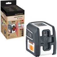
BeamControlMaster - Laser level Laserliner - Free user manual and instructions
Find the device manual for free BeamControlMaster Laserliner in PDF.
| Product type | Manual rotary laser level |
| Brand | Laserliner |
| Model | BeamControlMaster |
| Accuracy | ± 0.2 mm/m |
| Laser wavelength | 635 nm |
| Laser class | 2 (EN 60825-1:2014/AC:2017) |
| Laser power | < 1 mW |
| Power supply | 4 x LR6 (AA) 1.5 V batteries |
| Battery life | Approx. 40 hours |
| Operating temperature | 0 °C to 50 °C |
| Dimensions (L x W x H) | 175 x 150 x 135 mm |
| Weight | 678 g (batteries included) |
| Operating modes | Point mode, rotation mode, scan mode, manual receiver mode |
| Leveling | Manual horizontal and vertical |
| Rotation speed | 0 to 120 rpm (variable), 550 rpm (receiver mode) |
| Calibration | User control and adjustment (2.5 mm Allen key supplied) |
| Maintenance | Clean with a slightly damp cloth; remove batteries before prolonged storage |
| Safety | Class 2 laser: do not look into the beam |
| Optional accessories | SensoCommander 120 (receiver/remote control), universal mounting bracket |
Frequently Asked Questions - BeamControlMaster Laserliner
User questions about BeamControlMaster Laserliner
0 question about this device. Answer the ones you know or ask your own.
Ask a new question about this device
Download the instructions for your Laser level in PDF format for free! Find your manual BeamControlMaster - Laserliner and take your electronic device back in hand. On this page are published all the documents necessary for the use of your device. BeamControlMaster by Laserliner.
USER MANUAL BeamControlMaster Laserliner
natural_image
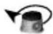
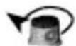
Exterior view of a white and black industrial device with control buttons and mechanical components (no visible text or symbols)
Laser
635 nm
auto man man
Laserliner
Laserliner
natural_image
Exterior view of a modern building with a tripod-mounted surveying instrument in front (no signage or text visible)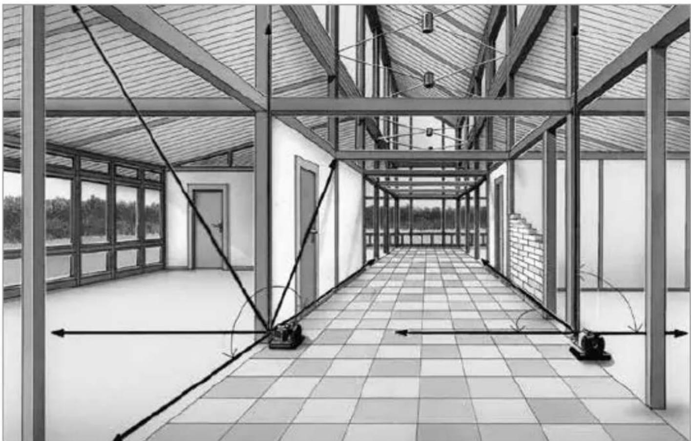
natural_image
Architectural interior view of a modern building corridor with exposed beams and tiled flooring (no text or symbols)!
natural_image
Warning symbol with a triangular triangle and central sunburst pattern (no text)natural_image
Close-up of a white industrial robot with four batteries and three battery cells, showing no visible text or symbols.Stromversorgung
Batterien
Bedienfeld

A Integralgriffe
B Bedienfeld
C Vertikallibelle Z
DBatteriefach
natural_image
Close-up of a vintage camera with visible lens and screen (no text or symbols)Bedienung
BCM einschalten:
natural_image
3D rendered mechanical component with cylindrical base and mounting holes, no visible text or symbolsPosition ändern
am Rotationslaser

mit SensoCommander
2. Scan-Modus:
natural_image
Illustration of a person sitting on a chair with abstract fan-like shapes in the background (no text or symbols)Position ändern
am Rotationslaser

mit SensoCommander
Scan-Winkel ändern


am Rotationslaser


mit SensoCommander
3. Rotations-Modus:
natural_image
3D rendered illustration of a person seated on a platform with a large oval background (no text or symbols)Completely read through the operating instructions, the „Warranty and Additional Information“ booklet as well as the latest information under the internet link at the end of these instructions. Follow the instructions they contain. This document must be kept in a safe place and if the laser device is passed on, this document must be passed on with it.
Manual rotary lasers
– Exact horizontal alignment
- Additional vertical levelling
– Easy alignment of slopes
– Laser modes: spot, scan, rotary and hand receiver mode
- Plumb function for synchronous working on floor and ceiling
– Special die-cast zinc platform guarantees long-term stability
- SpotLite marking: Effective prevention of parallax errors and easy marking of reference heights
General safety instructions
- The device must only be used in accordance with its intended purpose and within the scope of the specifications.
- The measuring tools and accessories are not toys. Keep out of reach of children.
- Modifications or changes to the device are not permitted, this will otherwise invalidate the approval and safety specifications.
- Do not expose the device to mechanical stress, extreme temperatures, moisture or significant vibration.
- The device must no longer be used if one or more of its functions fail or the battery charge is weak.
Safety instructions
Using class 2 lasers
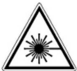
Laser radiation! Do not stare into the beam! Class 2 laser < 1 mW · 515 nm EN 60825-1:2014/AC:2017
- Attention: Do not look into the direct or reflected beam.
- Do not point the laser beam towards persons.
- If a person's eyes are exposed to class 2 laser radiation, they should shut their eyes and immediately move away from the beam.
- Under no circumstances should optical instruments (magnifying glass, microscope, binoculars) be used to look at the laser beam or reflections.
- Do not use the laser at eye level (1.40 ... 1.90 m)
- Reflective, specular or shiny surfaces must be covered whilst laser devices are in operation.
- In public areas shield off the laser beam with barriers and partitions wherever possible and identify the laser area with warning signs.
Safety instructions
Dealing with electromagnetic radiation
- The measuring device complies with electromagnetic compatibility regulations and limits in accordance with the EMC Directive 2014/30/EU.
- Local operating restrictions – for example, in hospitals, aircraft, petrolstations or in the vicinity of people with pacemakers – may apply. Electronic devices can potentially cause hazards or interference or be subject to hazards or interference.
Calibration
The measuring device should be calibrated and tested on a regular basis to ensure it is accurate and working properly. We recommend the measuring device is calibrated every 1 - 2 years. If necessary, contact your distributor or the UMAREX-LASERLINER service department.
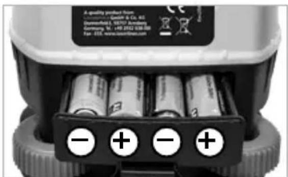
Inserting the batteries
Open the battery compartment and insert the batteries in accordance with the installation symbols, ensuring the correct polarity.
natural_image
Close-up of a white industrial robot with four batteries and three labeled negative and positive charges, no visible text or symbols on the main body.Power supply
Batteries
When the red LED is permanently flashing, the battery must be changed.
Connection of an external power supply unit
When connecting an external power supply unit the batteries will be bridged. It is not possible to charge storage batteries with the power supply unit in the rotation unit.
Please use only a suitable Laserliner mains unit.
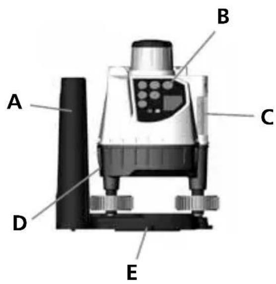
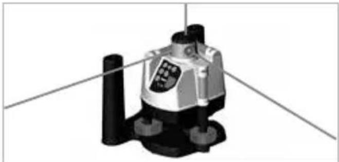
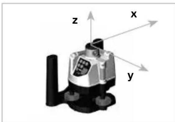
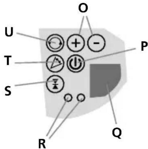
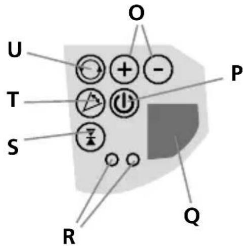
Control panel

A Integral handles
B Control panel
C Vertical Z vial
D Battery compartment
E 5/8 in socket
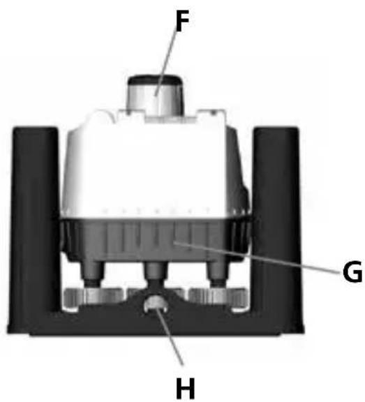
F Rotary head
G Battery compartment
H Threadet connection 5/8"
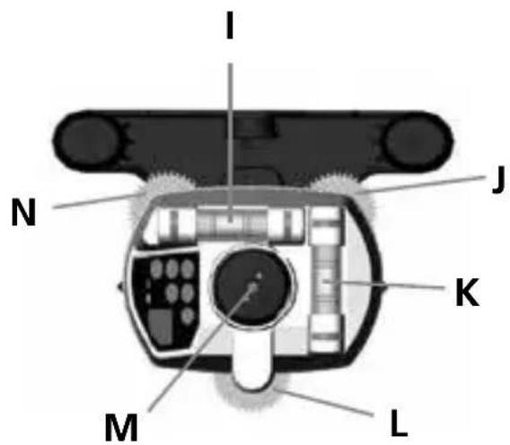
Horizontal X vial
J Levelling screw B
K Horizontal Y vial
L Levelling screw C
M Laser perpendicular beam
N Levelling screw A
O Speed / angular range
P On / Off
Q IR (infra-red) reception field
R LEDs
S Hand reveiver modus
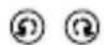
T Scan modus
U Rotation modus
SensoCommander – optional Accessories
The SensoCommander combines the fonctions of a laser receiver and a remote control.
SensoCommander 120:
(Diode on backside too)
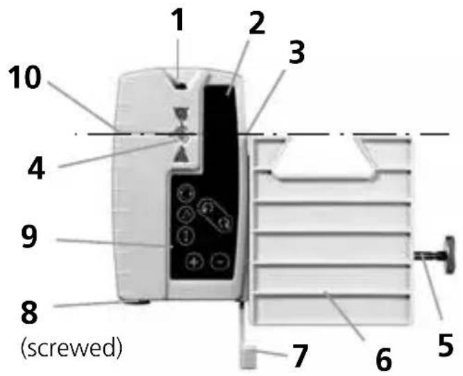
1 IR signal output
2 Laser beam reception field
3 SpotLite Marking LED
4 LEDs
5 Fastening screw
6 Universal holding device
7 Locker level
8 Battery cover
9 Control panel
10 Marking groove
Control panel SC 120
11 Position
12 speed / volume / angular range
13ON/OFFbutton
Hand receiver mode / switch over:
Fine measuring
Free-hand measuring
14 Scan mode
15 Rotation mode
!
The laser receiver has two tolerance settings: Precision and free-hand setting. On the SensoCommander 120, the settings are indicated by LEDs: precision setting: green; free-hand setting: orange.
Working with the SensoCommander (optional)
The SensoCommander can recognise the laser beam over long distances. Move the SensoCommander up and down through the laser beam until the middle display appears. Now mark the height on the all-round marking groove. The Spotlite additionally shows the measured height.
Universal mount (optional):
The receiver can be installed on levelling staffs with the aid of the universal mount. To do this, insert the universal mount into the laser receiver and secure on the levelling staff with the aid of the screw. To release the universal mount from the laser receiver, turn the quick release lock in the direction of the arrow.
Adjust horizontal
Start adjusting the vial (X) by turning the levelling screws (A) and (B).

Please look always vertically at the vial in order to avoid reading errors.
Now turn the levelling screw (C) to adjust the vial (Y).

Repeat the whole action, if necessary.
Adjust vertical
Set the BCM up vertically on its integral handles or mount the BCM onto a stand. Now adjust only the vial (Z) with the levelling screw (C).
Operation
Switch on BCM:
Hold the key ⏻ „On/Off“ pressed for 1 second, the head of BCM starts rotating, the rotation mode is activated.

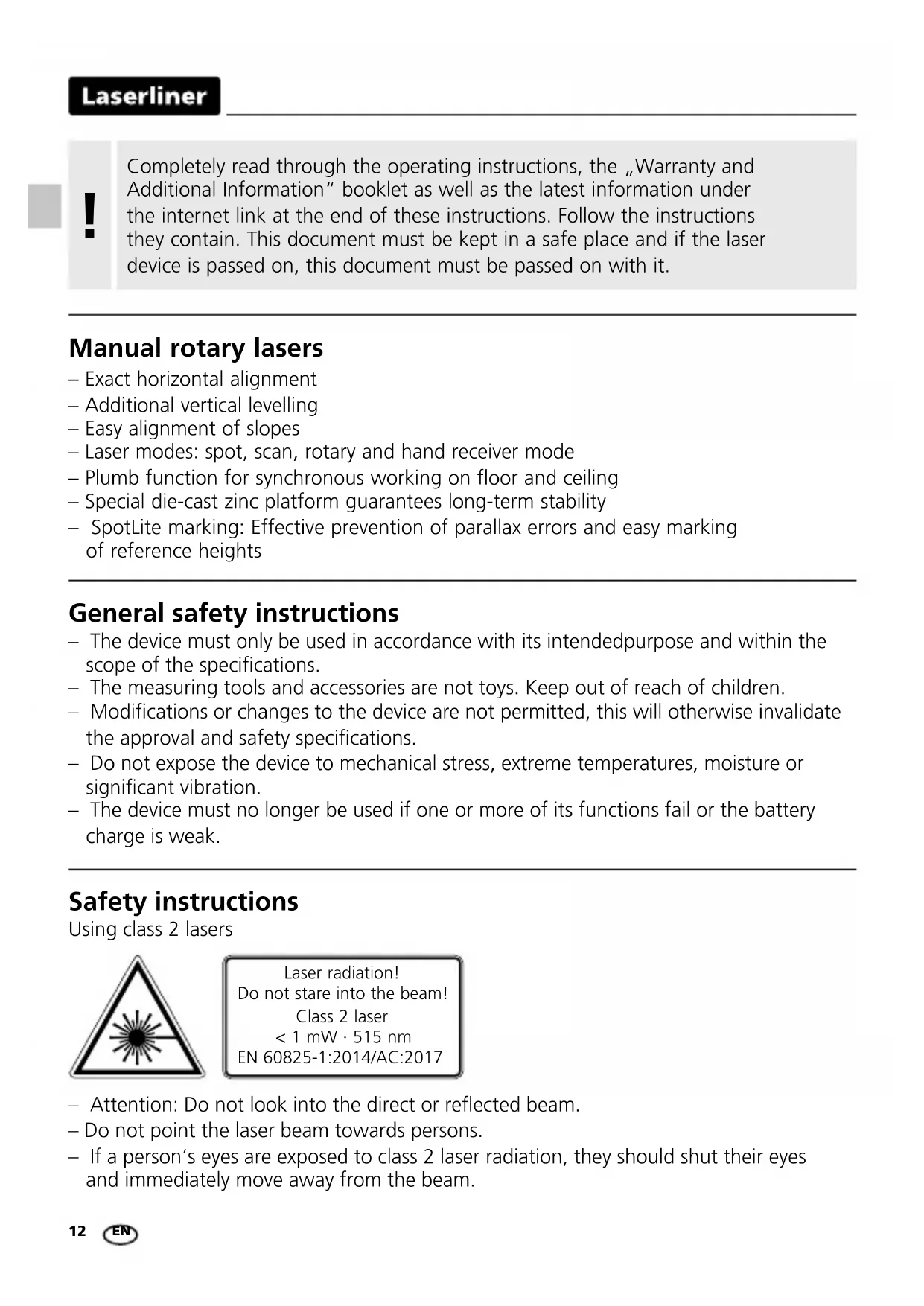
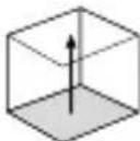
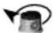
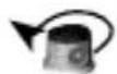
1. Spot mode:
The rotation laser sends out a laser beam exactly to thans ofe point over a great distance. In order to get into the spot mode reduce the speed by me to zero. ⏻.
natural_image
3D rendered mechanical component with cylindrical base and mounting holes, no visible text or symbolsChange position
on rotation laser

with SensoCommander
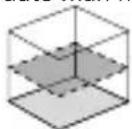
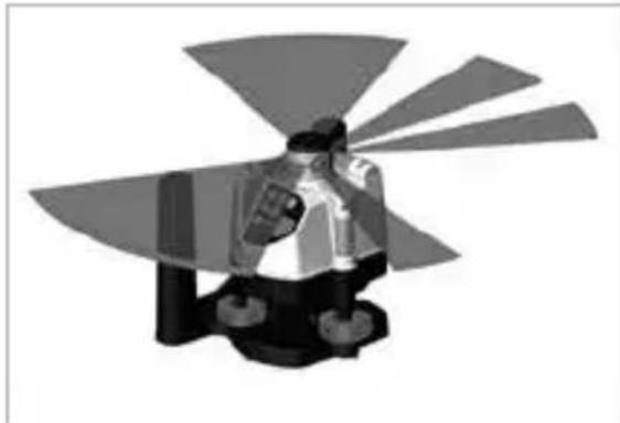
2. Scan mode:
A light-intensive segment of different breadth and position can be adjusted.
natural_image
3D rendered mechanical component with fan-like blades and central hub (no text or symbols)Activate mode

on rotation laser

with SensoCommander
Change position

on rotation laser


with SensoCommander
Change scan angle


on rotation laser


with SensoCommander
Laserliner
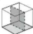
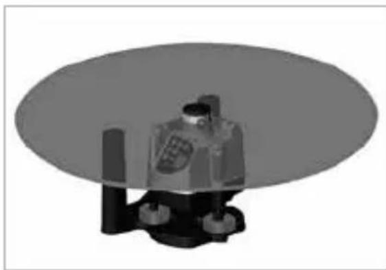
3. Rotation mode:
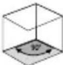
A laser beam rotating around 360^ with a speed of up to 200 rpm.
Activate mode
on rotation laser
with SensoCommander
Change speed
⊕ - on rotation laser
⊕ ⊖ with SensoCommander
natural_image
3D rendered mechanical component with a circular base and cylindrical base (no visible text or symbols)4. Hand receiver mode:
Optimum reception quality by constantly high speed of (maximum speed = 500 rpm).
Activate mode
on rotation laser
with SensoCommander
natural_image
3D mechanical component with x, y, z axis indicators (no text or symbols on the object itself)Note referring to all modes: The red LED lights up when the limit of a range has been reached (e.g. maximum speed, biggest scan angle).
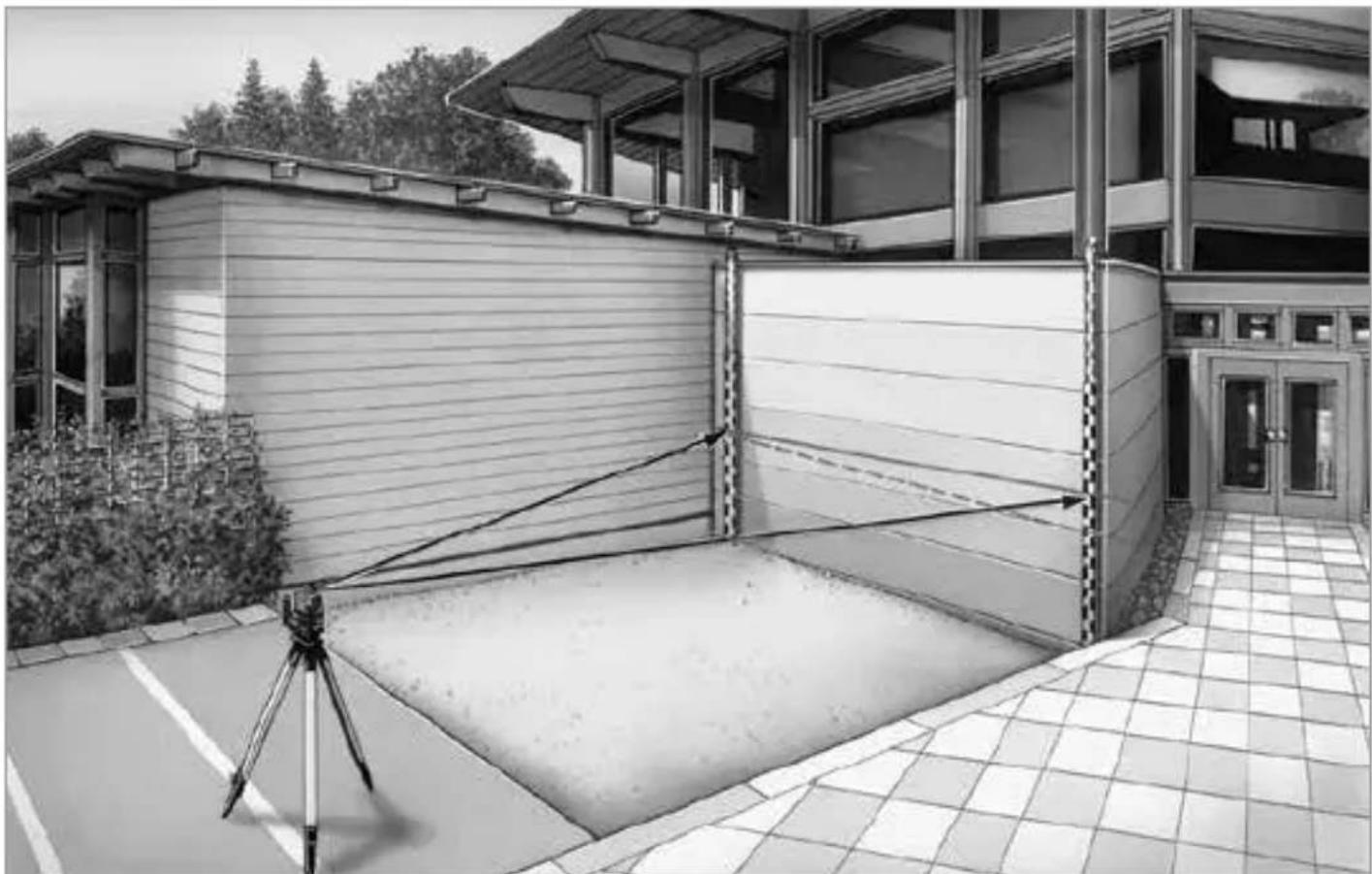
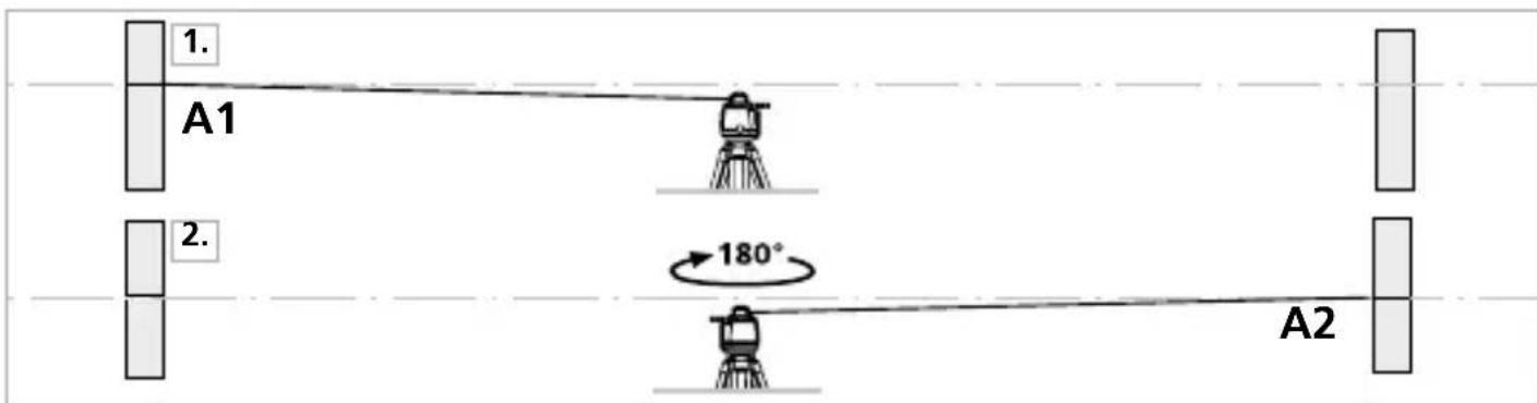
Preparing the calibration check
It is possible for you to check the calibration of the laser. To do this, position the device midway between 2 walls, which must be at least 5 metres apart. Switch the unit on and use the SensoLite to define the marking points. For optimum results, please use a tripod.
- Mark point A1 on the wall. (Use spot mode.)
- Turn the device through 180^ and mark point A2. You now have a horizontal reference between points A1 and A2.
Performing the calibration check
- Position the device as near as possible to the wall at the height of point A1. Now adjust the device in the X axis.

Mark either levelling screw A or B as a reference screw. Align the unit only with the other levelling screws.
-
Turn the device through 180^ and mark point A3. The difference between points A2 and A3 is the tolerance for the X axis.
-
To check the Y axis, repeat steps 3 and 4.
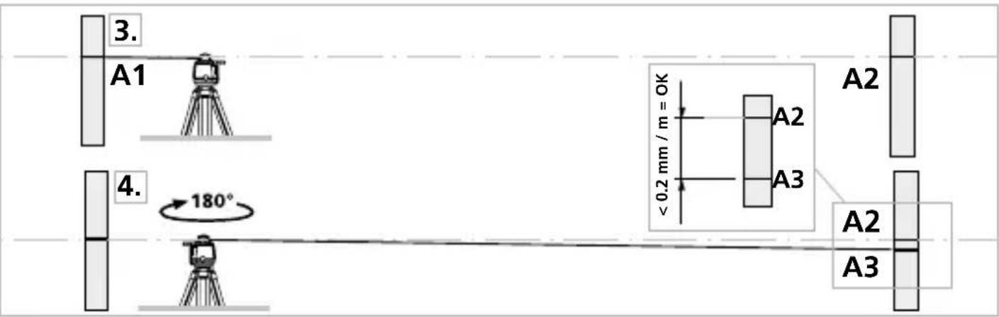

If points A2 and A3 are more than 0.2 mm / m apart on either the X, Y or Z axis, the device is in need of adjustment. Contact your authorised dealer or else the UMAREX-LASERLINER Service Department or follow the calibration instructions in the manual.
Calibration procedure
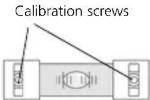
-
Once you have completed steps 1 to 4 and identified dots A2 (reference) and A3 (deviation), use the corresponding screws to level the laser so that dot A3 covers dot A2. During this process, the air bubble in the level will move out of its central position and stray to the side.
-
Remove the protective caps from the ends of the levels to expose the calibration screws. Turn the screws to calibrate the level (using the SW 2.5 socket wrench included in the scope of supply). Calibration is complete when the air bubble returns to the centre of the level.
-
Repeat for the remaining axes.
Information on maintenance and care
Clean all components with a damp cloth and do not use cleaning agents, scouring agents and solvents. Remove the battery(ies) before storing for longer periods. Store the device in a clean and dry place.
| Technical data (Subject to technical alterations. 20W46) | |
| Accuracy ± 0.2 mm / m | |
| Beam splitter 20" | |
| Speed of rotation 0 ... 120 rpm variable, 550 rpm for receivers | |
| Levelling manual | |
| Laser wavelength | 635 nm |
| Laser class 2 / < 1 mW (EN 60825-1:2014/AC:2017) | |
| Power supply 4 x 1.5V LR6 (AA) | |
| Operating time approx. 40 hours | |
| Operating conditions 0°C ... 50°C, | max. humidity 80% rH,no condensation, max. working altitude4000 m above sea level |
| Storage conditions -10°C ... 70°C, | max. humidity 80% rH |
| Dimensions (W x H x D) 175 x 150 x 135 mm | |
| Weight 678 g (incl. batteries) | |
| SensoCommander 120 (optional) | |
| Laser receive area max. 120 m | |
| Power supply 2 x 1.5V LR03 (AAA) | |
| Operating time approx. 70 hours | |
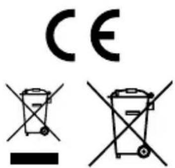
EU directives and disposal
This device complies with all necessary standards for the free movement of goods within the EU.
This product is an electric device and must be collected separately for disposal according to the European Directive on waste electrical and electronic equipment.
Further safety and supplementary notices at: http://laserliner.com/info?an=AAV
!
natural_image
Warning symbol with a triangular frame and central sunburst pattern (no text)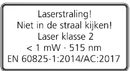
natural_image
Close-up of a white industrial robot with four batteries and labeled terminals (no readable text or symbols beyond basic markings)Stroomvoorziejning
Batterijen
Bedieningsveld
SensoCommander – optionale toebehoren
natural_image
3D rendered mechanical component with no visible text or symbolsPositie veranderen
aan de rotatielaser
met SensoCommander
2. Scan-Modus:
natural_image
Illustration of a mechanical device with blades and a central knob, no visible text or symbolsModus activeren

aan de rotatielaser

met SensoCommander
Positie veranderen

aan de rotatielaser

met SensoCommander
Scan-hoek veranderen


aan de rotatielaser


met SensoCommander
3. Rotatiemodus:
natural_image
3D rendered mechanical component with a cylindrical base and mounting feet, no visible text or symbols4. Handmatige ontvangst-modus:
natural_image
3D mechanical component with x, y, z axis indicators (no text or symbols on the object itself)
natural_image
Pure diagram of a mechanical or electrical component with no text, numbers, or symbolsnatural_image
Warning symbol with a triangular triangle and central starburst pattern (no text)natural_image
Close-up of a battery pack with four batteries and three negative charges, no visible text or symbolsStrømforsyning
Batterier
Betjeningsfelt

A Integralgreb
B Tastatur
C Vertikal-libelle Z
D Batterirum
E Geindtilslutnin 5/8"
F Rotationshoved
G Batterirum
H Geindtilslutnin 5/8"
natural_image
3D rendered mechanical component with no visible text or symbols2. Scan-modus:
natural_image
Illustration of a person standing on a platform with abstract fan-like shapes in the background (no text or symbols)Position ændres
På rotationslaseren


med SensoCommander
Scan-vinkel ændres


På rotationslaseren


med SensoCommander
Laserliner
3. Rotations-modus:
natural_image
3D rendered mechanical component with a cylindrical base and circular top, no visible text or symbolsnatural_image
Warning symbol with a triangular triangle containing a central starburst pattern (no text or numbers)natural_image
Close-up of a white industrial robot with four batteries and three battery icons, no visible text or symbols on the main body.Tableau de commande
natural_image
Mechanical device with labeled component C, no visible text or symbols on the device itselfUtilisation
natural_image
3D rendered mechanical component with cylindrical shaft and mounting base, no visible text or symbols2. Mode Scan :
natural_image
Illustration of a person in motion with abstract fan-like shapes (no text or symbols)Changement de position
Laser rotatif

SensoCommander
natural_image
3D rendered mechanical component with cylindrical base and circular housing, no visible text or symbolsnatural_image
3D mechanical component with x, y, z axis indicators (no text or symbols on the object itself)
natural_image
Warning symbol with a triangular frame and central sunburst pattern (no text)natural_image
Close-up of a portable electronic device showing four batteries with negative and positive charge labels (no readable text or symbols)Alimentación
Batería
Panel de control

A Empuñaduras integradas
B Panel de control
C Nivel vertical Z
natural_image
3D rendered mechanical component with cylindrical base and mounting holes, no visible text or symbolsCambio de posición
natural_image
Monochrome illustration of a person holding a device with fan blades, no text or symbols presentActive el modo

natural_image
3D rendered illustration of a robot-like figure seated on a platform, with no visible text or symbols4. Modo recepción manual:
natural_image
Pure electrical circuit lines without any symbolsnatural_image
Warning symbol with a triangular triangle containing a central starburst pattern (no text or numbers)natural_image
Close-up of a white robotic device with four batteries and labeled terminals (no readable text or symbols)Alimentazione
Batteria
natural_image
3D rendered mechanical component with cylindrical base and mounting holes, no visible text or symbolsnatural_image
Illustration of a person standing on a platform with abstract fan-like shapes in the background (no text or symbols)natural_image
3D rendered mechanical component with a cylindrical base and circular top, no visible text or symbolsnatural_image
3D mechanical component with x, y, z axis indicators (no text or symbols on the object itself)
natural_image
Warning symbol with a triangular triangle and central sunburst pattern (no text)Pobór mocy
Wymiana Baterii
Pole obsługi

A Uchwyt
B Konsola
C Libella pionowa Z
D Pojemnik baterii
natural_image
Mechanical device with cylindrical components and a labeled component (no visible text or symbols)Obstuga
Włączanie:
natural_image
3D rendered mechanical component with no visible text or symbolsZmiana pozycji
na niwelatorze

natural_image
3D rendered illustration of a person in uniform with arms crossed, holding a device (no text or symbols visible)Zmiana pozycji

na niwelatorze

natural_image
3D rendered mechanical component with a cylindrical base and circular top, no visible text or symbolsnatural_image
Diagram of a mechanical or electrical component with two blocks and a central oval feature, no visible text or symbols.natural_image
Construction site with concrete mixer and rebar grid, no visible text or symbolsSERVICE

Umarex GmbH & Co. KG
- Laserliner -
- Laserliner
- !
- Stromversorgung
- Batterien
- Bedienung
- BCM einschalten:
- Position ändern
- Scan-Modus:
- Scan-Winkel ändern
- Rotations-Modus:
- Manual rotary lasers
- General safety instructions
- Safety instructions
- Calibration
- Inserting the batteries
- Power supply
- Batteries
- Connection of an external power supply unit
- SensoCommander – optional Accessories
- Working with the SensoCommander (optional)
- Universal mount (optional):
- Adjust horizontal
- Adjust vertical
- Operation
- Switch on BCM:
- Spot mode:
- Change position
- Scan mode:
- Activate mode
- Change scan angle
- Rotation mode:
- Change speed
- Hand receiver mode:
- Preparing the calibration check
- Performing the calibration check
- Calibration procedure
- Information on maintenance and care
- EU directives and disposal
- Stroomvoorziejning
- Batterijen
- SensoCommander – optionale toebehoren
- Positie veranderen
- Modus activeren
- Scan-hoek veranderen
- Rotatiemodus:
- Handmatige ontvangst-modus:
- Strømforsyning
- Batterier
- Position ændres
- Scan-vinkel ændres
- Utilisation
- Mode Scan :
- Changement de position
- Alimentación
- Batería
- Cambio de posición
- Active el modo
- Modo recepción manual:
- Alimentazione
- Batteria
- Pobór mocy
- Wymiana Baterii
- Obstuga
- Włączanie:
- Zmiana pozycji
- Umarex GmbH & Co. KG
Brand : Laserliner
Model : BeamControlMaster
Category : Laser level