GWS 18V10 P Professional - Coffee grinder BOSCH - Free user manual and instructions
Find the device manual for free GWS 18V10 P Professional BOSCH in PDF.
| Product type | Cordless angle grinder |
| Brand | Bosch |
| Model | GWS 18V-10 P Professional |
| Rated voltage | 18 V |
| No-load speed | 9,000 rpm |
| Max. disc diameter | 125 mm |
| Spindle thread | M 14 |
| Weight (with battery) | 2.5 to 3.3 kg |
| Compatible batteries | GBA 18V... ≥ 4.0 Ah / ProCORE18V... ≥ 4.0 Ah |
| Recommended chargers | GAL 18..., GAX 18..., GAL 36... |
| Sound level (pressure) | 80 dB(A) |
| Sound level (power) | 91 dB(A) |
| Vibrations (grinding) | 6.5 m/s² |
| Vibrations (sanding) | 3.5 m/s² |
| Safety functions | KickBack Control, Drop Control, restart protection, immediate brake |
| Applications | Grinding, cutting, sanding, brushing, dry drilling |
| Usable materials | Metals, stone, plastics, composite materials |
| Battery charge indicator | Green LEDs (5 or 3 depending on battery type) |
| Maintenance | Clean the ventilation slots regularly with a soft brush |
Frequently Asked Questions - GWS 18V10 P Professional BOSCH
User questions about GWS 18V10 P Professional BOSCH
0 question about this device. Answer the ones you know or ask your own.
Ask a new question about this device
Download the instructions for your Coffee grinder in PDF format for free! Find your manual GWS 18V10 P Professional - BOSCH and take your electronic device back in hand. On this page are published all the documents necessary for the use of your device. GWS 18V10 P Professional by BOSCH.
USER MANUAL GWS 18V10 P Professional BOSCH
GWS 18V-10 P Professional
HEAVY DUTY
Robert Bosch Power Tools GmbH
70538 Sollgart
GERMANY
www.bosch-pt.com
160992A7ZT(2022.08)0/142

1609 92A 7ZT
en Original instructions
fr Notice originale
pt Manual original
es Manual original
General Power Tool SafetyWarnings
WARNING
Read all safety warnings and all instructions. Failure to follow the
warnings and instructions may result in electric shock, fire and/or serious injury.
Save all warnings and instructions for future reference.
The term "power tool" in the warnings refers to your mains-operated (corded) power tool or battery-operated (cordless) power tool.
Work area safety
- Keep work area clean and well lit. Cluttered or dark areas invite accidents.
- Do not operate power tools in explosive atmospheres, such as in the presence of flammable liquids, gases or dust. Power tools create sparks which may ignite the dust or fumes.
- Keep children and bystanders away while operating a power tool. Distractions can cause you to lose control.
Electrical safety
Power tool plugs must match the outlet. Never modify the plug in any way. Do not use any adapter plugs with earthed (grounded) power tools. Unmodified plugs and matching outlets will reduce risk of electric shock.
- Avoid body contact with earthed or grounded surfaces, such as pipes, radiators, ranges and refrigerators. There is an increased risk of electric shock if your body is earthed or grounded.
Do not expose power tools to rain or wet conditions. Water entering a power tool will increase the risk of electric shock.
Do not abuse the cord. Never use the cord for carrying, pulling or unplugging the power tool. Keep cord away from heat, oil, sharp edges or moving parts. Damaged or entangled cords increase the risk of electric shock.
When operating a power tool outdoors, use an extension cord suitable for outdoor use. Use of a cord suitable for outdoor use reduces the risk of electric shock..
If operating a power tool in a damp location is unavoidable, use a residual current device (RCD) protected supply. Use of an RCD reduces the risk of electric shock.
Personal safety
Stay alert, watch what you are doing and use common sense when operating a power tool. Do not use a power tool while you are tired or under the influence of drugs, alcohol or medication. A moment of inattention while operating power tools may result in serious personal injury.
Use personal protective equipment. Always wear eye protection. Protective equipment such as dust mask, non-skid safety shoes, hard hat, or hearing protection used for appropriate conditions will reduce personal injuries.
Prevent unintentional starting. Ensure the switch is in the off-position before connecting to power source and/or battery pack, picking up or carrying the tool.
Carrying power tools with your finger on the switch or energising power tools that have the switch on invites accidents.
Remove any adjusting key or wrench before turning the power tool on. A wrench or a key left attached to a rotating part of the power tool may result in personal injury.
Do not overreach. Keep proper footing and balance at all times. This enables better control of the power tool in unexpected situations.
Dress properly. Do not wear loose clothing or jewellery. Keep your hair, clothing and gloves away from moving parts. Loose clothes, jewellery or long hair can be caught in moving parts.
If devices are provided for the connection of dust extraction and collection facilities, ensure these are connected and properly used. Use of dust collection can reduce dust-related hazards.
Power tool use and care
Do not force the power tool. Use the correct power tool for your application. The correct power tool will do the job better and safer at the rate for which it was designed.
Do not use the power tool if the switch does not turn it on and off. Any power tool that cannot be controlled with the switch is dangerous and must be repaired.
- Disconnect the plug from the power source and/or the battery pack from the power tool before making any adjustments, changing accessories, or storing power tools. Such preventive safety measures reduce the risk of starting the power tool accidentally.
- Store idle power tools out of the reach of children and do not allow persons unfamiliar with the power tool or these instructions to operate the power tool. Power tools are dangerous in the hands of untrained users.
- Maintain power tools. Check for misalignment or binding of moving parts, breakage of parts and any other condition that may affect the power tool's operation. If damaged, have the power tool repaired before use. Many accidents are caused by poorly maintained power tools.
- Keep cutting tools sharp and clean. Properly maintained cutting tools with sharp cutting edges are less likely to bind and are easier to control.
Use the power tool, accessories and tool bits etc. in accordance with these instructions, taking into account the working conditions and the work to be per
8 | English
formed. Use of the power tool for operations different from those intended could result in a hazardous situation.
Battery tool use and care
- Recharge only with the charger specified by the manufacturer. A charger that is suitable for one type of battery pack may create a risk of fire when used with another battery pack.
- Use power tools only with specifically designated battery packs. Use of any other battery packs may create a risk of injury and fire.
When battery pack is not in use, keep it away from other metal objects, like paper clips, coins, keys, nails, screws or other small metal objects, that can make a connection from one terminal to another. Shorting the battery terminals together may cause burns or a fire.
Under abusive conditions, liquid may be ejected from the battery; avoid contact. If contact accidentally occurs, flush with water. If liquid contacts eyes, additionally seek medical help. Liquid ejected from the battery may cause irritation or burns.
Service
Have your power tool serviced by a qualified repair person using only identical replacement parts. This will ensure that the safety of the power tool is maintained.
SafetyWarnings for AngleGrinder
SafetyWarnings common for Grinding, Sanding, Wire Brushing or Abrasive Cutting Off operations
This power tool is intended to function as a grinder, sander, wire brush or cut-off tool. Read all safety warnings, instructions, illustrations and specifications provided with this power tool. Failure to follow all instructions listed below may result in electric shock, fire and/or serious injury.
Operations such as polishing are not recommended to be performed with this power tool. Operations for which the power tool was not designed may create a hazard and cause personal injury.
- Do not use accessories which are not specifically designed and recommended by the tool manufacturer. Just because the accessory can be attached to your power tool, it does not assure safe operation.
The rated speed of the accessory must be at least equal to the maximum speed marked on the power tool. Accessories running faster than their rated speed can break and fly apart.
The outside diameter and the thickness of your accessory must be within the capacity rating of your power tool. Incorrectly sized accessories cannot be adequately guarded or controlled.
- Threaded mounting of accessories must match the grinder spindle thread. For accessories mounted by flanges, the arbour hole of the accessory must fit the locating diameter of the flange. Accessories that do not
match the mounting hardware of the power tool will run out of balance, vibrate excessively and may cause loss of control.
- Do not use a damaged accessory. Before each use inspect the accessory such as abrasive wheels for chips and cracks, backing pad for cracks, tear or excess wear, wire brush for loose or cracked wires. If power tool or accessory is dropped, inspect for damage or install an undamaged accessory. After inspecting and installing an accessory, position yourself and bystanders away from the plane of the rotating accessory and run the power tool at maximum no load speed for one minute. Damaged accessories will normally break apart during this test time.
Wear personal protective equipment. Depending on application, use face shield, safety goggles or safety glasses. As appropriate, wear dust mask, hearing protectors, gloves and workshop apron capable of stopping small abrasive or workpiece fragments. The eye protection must be capable of stopping flying debris generated by various operations. The dust mask or respirator must be capable of filtrating particles generated by your operation. Prolonged exposure to high intensity noise may cause hearing loss. - Keep bystanders a safe distance away from work area. Anyone entering the work area must wear personal protective equipment. Fragments of workpiece or of a broken accessory may fly away and cause injury beyond immediate area of operation.
Hold the power tool by insulated gripping surfaces only, when performing an operation where the cutting accessory may contact hidden wiring. Contact with a "live" wire will also make exposed metal parts of the power tool "live" and could give the operator an electric shock. - Never lay the power tool down until the accessory has come to a complete stop. The spinning accessory may grab the surface and pull the power tool out of your control.
Do not run the power tool while carrying it at your side. Accidental contact with the spinning accessory could snag your clothing, pulling the accessory into your body.
Regularly clean the power tool's air vents. The motor's fan will draw the dust inside the housing and excessive accumulation of powdered metal may cause electrical hazards.
Do not operate the power tool near flammable materials. Sparks could ignite these materials.
Do not use accessories that require liquid coolants. Using water or other liquid coolants may result in electrocution or shock.
Kickback and RelatedWarnings
Kickback is a sudden reaction to a pinched or snagged rotating wheel, backing pad, brush or any other accessory. Pinching or snagging causes rapid stalling of the rotating access
ory which in turn causes the uncontrolled power tool to be forced in the direction opposite of the accessory's rotation at the point of the binding.
For example, if an abrasive wheel is snagged or pinched by the workpiece, the edge of the wheel that is entering into the pinch point can dig into the surface of the material causing the wheel to climb out or kick out. The wheel may either jump toward or away from the operator, depending on direction of the wheel's movement at the point of pinching. Abrasive wheels may also break under these conditions. Kickback is the result of power tool misuse and/or incorrect operating procedures or conditions and can be avoided by taking proper precautions as given below.
- Maintain a firm grip on the power tool and position your body and arm to allow you to resist kickback forces. Always use auxiliary handle, if provided, for maximum control over kickback or torque reaction during start-up. The operator can control torque reactions or kickback forces, if proper precautions are taken.
Never place your hand near the rotating accessory. Accessory may kickback over your hand.
Do not position your body in the area where power tool will move if kickback occurs. Kickback will propel the tool in direction opposite to the wheel's movement at the point of snagging. - Use special care when working corners, sharp edges etc. Avoid bouncing and snagging the accessory. Corners, sharp edges or bouncing have a tendency to snag the rotating accessory and cause loss of control or kickback.
Do not attach a saw chain woodcarving blade or toothed saw blade. Such blades create frequent kickback and loss of control.
SafetyWarnings specific for Grinding and Abrasive Cutting-Off operations
- Use only wheel types that are recommended for your power tool and the specific guard designed for the selected wheel. Wheels for which the power tool was not designed cannot be adequately guarded and are unsafe.
The grinding surface of centre depressed wheels must be mounted below the plane of the guard lip. An improperly mounted wheel that projects through the plane of the guard lip cannot be adequately protected.
The guard must be securely attached to the power tool and positioned for maximum safety, so the least amount of wheel is exposed towards the operator. The guard helps to protect operator from broken wheel fragments, accidental contact with wheel and sparks that could ignite clothing. - Wheels must be used only for recommended applications. For example: do not grind with the side of cut-off wheel. Abrasive cut-off wheels are intended for peripheral grinding, side forces applied to these wheels may cause them to shatter.
Always use undamaged wheel flanges that are of correct size and shape for your selected wheel. Proper
wheel flanges support the wheel thus reducing the possibility of wheel breakage. Flanges for cut-off wheels may be different from grinding wheel flanges.
Do not use worn down wheels from larger power tools. Wheel intended for larger power tool is not suitable for the higher speed of a smaller tool and may burst.
Additional Safety Warnings specific for Abrasive Cutting Off operations
Do not "jam" the cut-off wheel or apply excessive pressure. Do not attempt to make an excessive depth of cut. Overstressing the wheel increases the loading and susceptibility to twisting or binding of the wheel in the cut and the possibility of kickback or wheel breakage.
Do not position your body in line with and behind the rotating wheel. When the wheel, at the point of operation, is moving away from your body, the possible kickback may propel the spinning wheel and the power tool directly at you.
When wheel is binding or when interrupting a cut for any reason, switch off the power tool and hold the power tool motionless until the wheel comes to a complete stop. Never attempt to remove the cut-off wheel from the cut while the wheel is in motion otherwise kickback may occur. Investigate and take corrective action to eliminate the cause of wheel binding.
- Do not restart the cutting operation in the workpiece. Let the wheel reach full speed and carefully re-enter the cut. The wheel may bind, walk up or kickback if the power tool is restarted in the workpiece.
Support panels or any oversized workpiece to minimize the risk of wheel pinching and kickback. Large workpieces tend to sag under their own weight. Supports must be placed under the workpiece near the line of cut and near the edge of the workpiece on both sides of the wheel.
Use extra caution when making a "pocket cut" into existing walls or other blind areas. The protruding wheel may cut gas or water pipes, electrical wiring or objects that can cause kickback.
SafetyWarnings specific for Sanding operations
Do not use excessively oversized sanding disc paper. Follow manufacturers recommendations, when selecting sanding paper. Larger sanding paper extending beyond the sanding pad presents a laceration hazard and may cause snagging, tearing of the disc, or kickback.
SafetyWarnings specific for Wire Brushing operations
Be aware that wire bristles are thrown by the brush even during ordinary operation. Do not overstress the wires by applying excessive load to the brush The wire bristles can easily penetrate light clothing and/or skin.
If the use of a guard is recommended for wire brushing, do not allow any interference of the wire wheel or brush with the guard. Wire wheel or brush may expand in diameter due to work load and centrifugal forces.
10 | English
Additional safety information

Wear safety goggles.
Use suitable detectors to determine if there are hidden supply lines or contact the local utility company for assistance. Contact with electric cables can cause fire and electric shock. Damaging gas lines can lead to explosion. Breaking water pipes causes property damage.
Do not touch grinding and cutting discs until they have cooled down. The discs can become very hot while working.
Release the On/Off switch and set it to the Off position when the power supply is interrupted, e.g. when the battery pack is removed. This prevents uncontrolled restarting.
- Secure the workpiece. A workpiece clamped with clamping devices or in a vice is held more secure than by hand.
In case of damage and improper use of the battery, vapours may be emitted. The battery can set alight or explode. Ensure the area is well ventilated and seek medical attention should you experience any adverse effects. The vapours may irritate the respiratory system.
Do not open the battery. There is a risk of short-circuiting.
The battery can be damaged by pointed objects such as nails or screwdrivers or by force applied externally. An internal short circuit may occur, causing the battery to burn, smoke, explode or overheat.
Only use the battery in the manufacturer's products. This is the only way in which you can protect the battery against dangerous overload.
Protect the battery against heat, e.g. against continuous intense sunlight, fire, dirt, water and moisture. There is a risk of explosion and short-circuiting.
Product Description and Specifications

Read all the safety and general instructions. Failure to observe the safety and general instructions may result in electric shock, fire and/or serious injury.
Please observe the illustrations at the beginning of this operating manual.
Intended use
The power tool is intended for cutting and brushing metal, stone, plastic and composite materials, roughing metal, plastic and composite materials as well as making holes in stone materials using diamond annular cutters, without the
use of water. Make sure that the correct protective guard is used (see "Operation", page 15).
Sufficient dust extraction must be provided when cutting stone.
With approved abrasive tools, the power tool can be used for sanding with sanding discs.
The power tool must not be used to grind stone materials with diamond grinding heads.
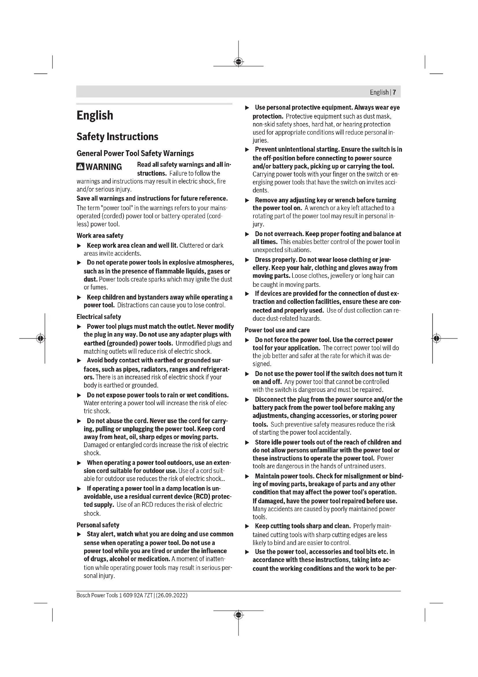
Product Features
The numbering of the product features refers to the diagram of the power tool on the graphics page.
(1) Unlocking lever for protective guard
(2) Direction of rotation arrow on housing
(3) Spindle lock button
(4) Rechargeable battery a)
(5) Rechargeable battery release button
(6) On/off switch
(7) Unlocking lever for on/off switch
(8) Standard auxiliary handle (insulated gripping surface) ^a)
(9) Vibration-damping auxiliary handle (insulated gripping surface)
(10) Extraction guard for grinding
(11) Protective guard for grinding
(12) Protective guard for cutting
(13) Mounting flange
(14) Carbide grinding head
(15) Grinding disca)
(16) Disc brush (M 14) ^a)
(17) Cutting disca
(18) Diamond cutting disca
(19) Clamping nut (M 10)
(20) Quick-clamping nut with bar (M 14)
(21) Handle (insulated gripping surface)
(22) Grinding spindle
(23) Hand guard a)
(24) Rubber sanding pad
(25) Abrasive disc
(26) Round nuta
(27) Two-pin spanner for clamping nut/round nuta
(28) Cup brush
(29) Conical brush
(30) Diamond annular cutter
(31) Open-ended spannera
(32) Extraction guard for cutting with cutting guidesa
a) Accessories shown or described are not included with the product as standard. You can find the complete selection of accessories in our accessories range.
Technical Data
| Angle Grinder GWS 18V-10 P GWS 18V-10 P | ||
| Article number | 3601 JJ4 18. 3601 JJ4 1K. | |
| Rated voltage V= 18 18 | ||
| Rated no-load speedA) | min1 | 9000 9000 |
| Max. grinding disc diameter/rubber sanding pad diameter mm 100 125 | ||
| Grinding spindle thread M 10 M 14 | ||
| Max. thread length of grinding spindle mm 22 22 | ||
| Kickback stop●● | ||
| Restart protection●● | ||
| Run-out brake●● | ||
| Weight according to EPTA-Procedure 01:2014B) | kg 2.3-3.2 2.5-3.3 | |
| Recommended ambient temperature during charging | °C | 0 to +35 0 to +35 |
| Permitted ambient temperature during operationC) and dur-ing storage | °C -20 to +50 -20 to +50 | |
| Compatible rechargeable batteries | GBA 18V... ProCORE18V... GBA 18V... ProCORE18V... | |
| Recommended rechargeable batteries | GBA 18V... ≥ 4.0Ah ProCORE18V... ≥ 4.0Ah GBA 18V... ≥ 4.0Ah ProCORE18V... ≥ 4.0Ah | |
| Recommended chargers | GAL 18... GAL 18... | |
| GAX 18... GAX 18... | ||
| GAL 36... GAL 36... | ||
A) Rated no-load speed for the selection of appropriate grinding tools in accordance with EN 60745. The actual speed is lower for safety reasons.
B)Depends on rechargeable battery, protective guard, and auxiliary handle in use
C) Limited performance at temperatures < 0^ C
Noise/Vibration Information
Noise emission values determined according to EN 60745-2-3.
Typically the A-weighted noise level of the power tool are: 80 dB(A); sound power level 91 dB(A). Uncertainty K = 3 dB.
Wear hearing protection!
Vibration total values a, (triax vector sum) and uncertainty K determined according to EN 60745-2-3:
Surface grinding (roughing):
$$ a _ {1} = 6. 5 \mathrm {m} / \mathrm {s} ^ {2}, K = 1. 5 \mathrm {m} / \mathrm {s} ^ {2}, $$
Disc sanding:
$$ a _ {h} = 3. 5 \mathrm {m} / \mathrm {s} ^ {2}, K = 1. 5 \mathrm {m} / \mathrm {s} ^ {2}. $$
The vibration level given in these instructions has been measured in accordance with a standardised measuring procedure and may be used to compare power tools. It can also be used for a preliminary estimation of exposure to vibration.
The stated vibration level applies to the main applications of the power tool. However, if the power tool is used for different applications, with different application tools or poorly maintained, the vibration level may differ. This can significantly increase the exposure to vibration over the total working period.
To estimate the exposure to vibration accurately, the times when the tool is switched off or when it is running but not actually being used should also be taken into account. This can significantly reduce the exposure to vibration over the total working period.
Implement additional safety measures to protect the operator from the effects of vibration, such as servicing the power tool and application tools, keeping the hands warm, and organising workflows correctly.
Kickback control

If there is a sudden kickback in the power tool, e.g. jamming in a separating cut, the power supply to the motor will be interrupted electronically.
To restart the tool, set the On/Off switch (6) to the "off" position and then switch the power tool on again.
Restart protection
The restart protection feature prevents the power tool from uncontrolled starting after the power supply to it has been interrupted.
To restart the tool, set the on/off switch (6) to the off position and then switch the power tool on again.
12 | English
Drop control

The integrated impact shutdown switches the power tool off as soon as it hits the floor. To restart the tool, set the on/off switch (6) to the "off" position and then switch the power tool on again.
Run-out brake

The power tool is fitted with the electronic Bosch Brake System. When it is switched off, the abrasive tool is brought to a complete stop within a few seconds. This means that the run-out time is significantly shorter than for angle
grinders without a run-out brake and enables the power tool to be set down sooner.
Rechargeable battery
Bosch sells some cordless power tools without a rechargeable battery. You can tell whether a rechargeable battery is included with the power tool by looking at the packaging.
Charging the battery
Use only the chargers listed in the technical data. Only these chargers are matched to the lithium-ion battery of your power tool.
Note: Lithium-ion rechargeable batteries are supplied partially charged according to international transport regulations. To ensure full rechargeable battery capacity, fully charge the rechargeable battery before using your tool for the first time.
Inserting the Battery
Push the charged battery into the battery holder until it clicks into place.
Removing the Battery
To remove the rechargeable battery, press the battery release button and pull the battery out. Do not use force to do this.
The rechargeable battery has two locking levels to prevent the battery from falling out if the battery release button is pressed unintentionally. The rechargeable battery is held in place by a spring when fitted in the power tool.
Battery charge indicator
The green LEDs on the battery charge indicator indicate the state of charge of the battery. For safety reasons, it is only possible to check the state of charge when the power tool is not in operation.
Press the button for the battery charge indicator or show the state of charge. This is also possible when the battery is removed.
If no LED lights up after pressing the button for the battery charge indicator, then the battery is defective and must be replaced.
Battery model GBA 18V...


LED Capacity
3 × continuous green light 60 - 100%
2× continuous green light 30 - 60%
1 × continuous green light 5 - 30 %
1 × flashing green light 0 - 5 %
Battery model ProCORE18V...


LED Capacity
5× continuous green light 80 - 100%
4× continuous green light 60 - 80%
3 × continuous green light 40 - 60%
2× continuous green light 20-40%
1× continuous green light 5-20%
1× flashing green light 0 - 5%
Recommendations for Optimal Handling of the Battery
Protect the battery against moisture and water.
Only store the battery within a temperature range of -20 to 50^ . Do not leave the battery in your car in the summer, for example.
Occasionally clean the ventilation slots on the battery using a soft brush that is clean and dry.
A significantly reduced operating time after charging indicates that the battery has deteriorated and must be replaced.
Follow the instructions on correct disposal.
Fitting
Fitting Protective Equipment
- Remove the battery from the power tool before carrying out work on the power tool (e.g. maintenance, changing tool, etc.). The battery should also be removed for transport and storage. There is risk of injury from unintentionally pressing the on/off switch.
Note: If the grinding disc breaks during operation or the holding fixtures on the protective guard/power tool become damaged, the power tool must be sent to the after-sales service immediately; see the "After-Sales Service and Application Service" section for addresses.
Protective guard for grinding
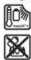
Place the protective guard (11) onto the holder on the power tool until the coding cams of the protective guard are aligned with the holder. When doing so, press and hold the unlocking lever (1). Press the protective guard (11) onto the spindle collar until the shoulder of the protective guard is sitting on the flange of the power tool and rotate the protective guard until it audibly clicks into place.
Adjust the position of the protective guard (11) to meet the requirements of the operation. To do this, push the unlocking lever (1) upward and rotate the protective guard (11) into the required position.
Always position the protective guard (11) such that the two cams on the unlocking lever (1) engage in the corresponding openings on the protective guard (11).
Adjust the protective guard (11) such that sparking in the direction of the operator is prevented.
The protective guard (11) must only be adjustable while the unlocking lever (1) is actuated. Otherwise, the power tool must not be used any more under any circumstances and must be sent to the after-sales service.
Note: The coding cams on the protective guard (11) ensure that only a protective guard that is suitable for the power tool can be fitted.
Extraction guard for sanding
For low-dust grinding of paints, lacquers and plastics in conjunction with carbide grinding heads (14), you can use the extraction guard (10). The extraction guard (10) is not suitable for machining metal.
A suitable Bosch dust extractor can be connected to the extraction guard (10). To do so, insert the vacuum hose with dust extraction adapter into the provided receiving connection of the extraction guard.
Protective guard for cutting
Always use the protective guard for cutting (12) when cutting with bonded abrasives.
Provide sufficient dust extraction when cutting stone.
The protective guard for cutting (12) is fitted in the same way as the protective guard for grinding (11).
Extraction guard for cutting with a guide block
The extraction guard for cutting with a guide block (32) is fitted in the same way as the protective guard for grinding (11).
Hand guard
Always fit the hand guard (23) when working with the rubber sanding pad (24) or with the cup brush/conical brush/diamond annular cutter.
Attach the hand guard (23) to the auxiliary handle (8)/(9).
Standard auxiliary handle/low-vibration auxiliary handle Screw the auxiliary handle (8)/(9) on the right or left of the machine head depending on the working method.
Do not operate your power tool without the auxiliary handle (8)/(9).
Do not continue to use the power tool if the auxiliary handle (8)/(9) is damaged. Do not make any alterations to the auxiliary handle (8)/(9).
Vibration Control
The low-vibration auxiliary handle (9) reduces vibration, enabling the tool to be used safely and more com
fortably.
Fitting the Abrasive Tools
- Remove the battery from the power tool before carrying out work on the power tool (e.g. maintenance, changing tool, etc.). The battery should also be removed for transport and storage. There is risk of injury from unintentionally pressing the on/off switch.
Do not touch grinding and cutting discs until they have cooled down. The discs can become very hot while working.
Clean the grinding spindle (22) and all the parts to be fitted. Lock the grinding spindle with the spindle lock button (3) before clamping and releasing the abrasive tools.
Do not press the spindle lock button while the grinding spindle is moving. The power tool may become damaged if you do this.
Grinding/cutting disc with 125 mm diameter
Pay attention to the dimensions of the abrasive tools. The diameter of the hole must match that of the mounting flange. Do not use an adapter or reducer.
When using diamond cutting discs, ensure that the arrow indicating the direction of rotation on the diamond cutting disc matches the direction of rotation of the power tool (see the direction of rotation arrow on the machine head).
See the graphics page for assembly instructions.
Use the quick-clamping nut (20) to secure the grinding/cutting disc without the need for additional tools.
Only use the quick-clamping nut (20) for grinding/cutting discs up to a maximum diameter of 125mm .
The quick-clamping nut (20) may be used only for grinding or cutting discs.
Only use quick-clamping nuts (20) that are in good working order and not damaged.
- When screwing on, make sure that the printed side of the quick-clamping nut (20) is not facing the grinding disc.
14|English
Always secure a grinding/cutting disc using only the quick-clamping nut (20) supplied.
Press the spindle lock button (3) to lock the grinding spindle. To tighten the quick-clamping nut (20), fold up the bar and turn the quick-clamping nut firmly clockwise. Then fold down the bar to secure the quick-clamping nut. It is not sufficient to tighten the disc along the edge.
Quick-clamping nuts (20) that are properly secured and not damaged can be removed by hand. To do this, fold up the bar and turn the quick-clamping nut firmly anticlockwise. If the quick-clamping nut is stuck, do not attempt to loosen it with a tool - always use a two-pin spanner.
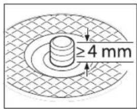
After fitting the mounting flange and the grinding/cutting disc, the free thread length of the grinding spindle must be at least 4 mm.
Ensure that the abrasive tool is firmly seated, so that
it does not twist away from the spindle in the runout of the power tool.
Mounting flange for grinding spindle M 14:
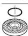
A plastic part (O-ring) is fitted around the cent-ring collar in the mounting flange (13). If the O-ring is missing or damaged, the mounting flange (13) must be replaced before operation can resume.
After fitting the abrasive tool, check that the abrasive tool is fitted correctly and can turn freely before switching on the power tool. Make sure that the abrasive tool does not brush against the protective guard or other parts.
Grinding/Cutting Disc with Diameter 100 mm The quick clamping nut with bar (20) is not recommended to be used with 100mm cutting/grinding disc.
Pay attention to the dimensions of the abrasive tools. The diameter of the hole must match that of the hub flange. Do not use an adapter or reducer.
When using diamond cutting discs, ensure that the arrow indicating the direction of rotation on the diamond cutting disc matches the direction of rotation of the power tool (see the direction of rotation arrow on the machine head).
See the graphics page for fitting instructions.
To fasten the grinding/cutting disc, screw on the clamping nut (19) and tighten with the two-pin spanner.
After fitting the abrasive tool, check that the abrasive tool is fitted correctly and can turn freely before switching on the power tool. Make sure that the abrasive tool does not brush against the protective guard or other parts.
Approved abrasive tools
You can use all the abrasive tools mentioned in these operating instructions.
The permissible speed [^-1] or the circumferential speed [m / s] of the abrasive tools used must at least match the values given in the table.
It is therefore important to observe the permissible rotational/circumferential speed on the label of the abrasive tool.
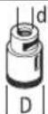
| Max. [mm] [mm] | |||||
| D bd [min] | 1] [m/s] | ||||
| b | 100 | 6.3 | 16.0 | 9000 | 80 |
| 125 | 7 | 22.2 | 9000 | 80 | |
| D | 100 | - | - | 9000 | 80 |
| 125 | - | - | 9000 | 80 | |
| b | 70 | 30 | M 10 | 9000 | 45 |
| 75 | 30 | M 14 | 9000 | 45 | |
82-M14900080
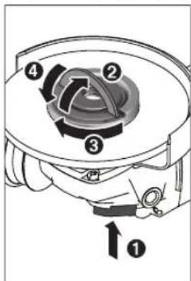
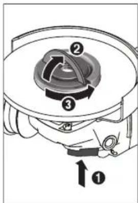
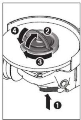
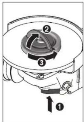
Rotating the machine head (see figure B)
- Remove the battery from the power tool before carrying out work on the power tool (e.g. maintenance, changing tool, etc.). The battery should also be removed for transport and storage. There is risk of injury from unintentionally pressing the on/off switch.
The machine head can be rotated in 90^ increments. In this way, the on/off switch can be brought into a more favourable handling position for particular applications, e.g. for left-handed tool users.
Completely unscrew the four screws (1). Rotate the machine head carefully, without removing it from the hous
ing, into the new position (2). Screw in and retighten the four screws (3).
Dust/Chip Extraction
Dust from materials such as lead-containing coatings, some wood types, minerals and metal can be harmful to one's health. Touching or breathing in the dust can cause allergic reactions and/or lead to respiratory infections of the user or bystanders.
Certain dust, such as oak or beech dust, is considered carcinogenic, especially in connection with wood-treatment additives (chromate, wood preservative). Materials containing asbestos may only be worked by specialists.
-
Provide for good ventilation of the working place.
-
It is recommended to wear a P2 filter-class respirator.
Observe the relevant regulations in your country for the materials to be worked.
- Avoid dust accumulation at the workplace. Dust can easily ignite.
Operation
Do not load the power tool so heavily that it comes to a stop.
- Remove the battery from the power tool before carrying out work on the power tool (e.g. maintenance, changing tool, etc.). The battery should also be removed for transport and storage. There is risk of injury from unintentionally pressing the on/off switch.
Exercise caution when cutting slots in structural walls; see the "Information on structural design" section.
- Clamp the workpiece if it is not secure under its own weight.
If the power tool has been subjected to a heavy load, continue to run it at no-load for several minutes to cool down the accessory.
Do not use the power tool with a cut-off stand.
Do not touch grinding and cutting discs until they have cooled down. The discs can become very hot while working.
If the power tool becomes electrostatically charged, the built-in electronics will switch the power tool off. To start the power tool, push the unlocking lever (7) forwards and then push the on/off switch (6) up.
Working advice
Rough grinding
Never use cutting discs for rough grinding.
The best rough grinding results are achieved with a set angle of 30^ to 40^ . Move the power tool back and forth with moderate pressure. This will ensure that the workpiece does not become too hot or discolour and that grooves are not formed.
Surface grinding with flap disc
Always use the protective guard for grinding (11) when grinding with the flap disc.
The flap disc (accessory) enables you to machine curved surfaces and profiles. Flap discs have a considerably longer service life, lower noise levels and lower grinding temperatures than conventional grinding discs.
Surface grinding with sanding disc
Always fit the hand guard (23) when working with the rubber sanding pad (24).
Grinding with a sanding disc can be done without a protective guard.
See the graphics page for fitting instructions.
Screw on the round nut (26) and tighten it with the two-pin spanner.
Cup brush/disc brush/conical brush
Always use the protective guard for grinding (11) when brushing with disc brushes. Brushing with cup brushes/conical brushes can be performed without the protective guard.
Always fit the hand guard (23) when working with the cup brush or conical brush.
The wires of the disc brush can get caught on the protective guard and break, if the maximum permitted dimensions of the disc brushes are exceeded.
See the graphics page for fitting instructions.
The cup brush/conical brush/disc brush with M14 thread must be screwed onto the grinding spindle until it rests firmly against the grinding spindle flange at the end of the grinding spindle thread. Tighten the cup brush/conical brush/disc brush with an open-ended spanner.
Cutting metal
Always use the protective guard for cutting (12) when cutting with bonded abrasives.
When carrying out abrasive cutting, use a moderate feed that is suited to the material being machined. Do not exert pressure on the cutting disc and do not tilt or swing the power tool.
Do not attempt to reduce the speed of a cutting disc coming to a stop by applying pressure from the side.
The power tool must always work in an up-grinding motion. Otherwise there is a risk that it will be pushed uncontrolled out of the cut.
For best results when cutting profiles and rectangular tubing, start at the smallest cross section.
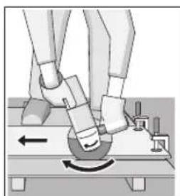
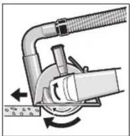
Cutting Stone (see figure A)
Provide sufficient dust extraction when cutting stone.
Wear a dust mask.
16|English
The power tool may be used only for dry cutting/grinding.
For best results when cutting stone, use a diamond cutting disc.
When using the extraction guard for cutting with a cutting guide (32), the vacuum cleaner must be approved for vacuuming stone dust. Suitable vacuum cleaners are available from Bosch.
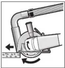
Switch on the power tool and position it with the front part of the cutting guide on the workpiece. Move the power tool with a moderate feed motion that is suited to the material being machined.
When cutting especially hard materials such as con
crete with a high pebble content, the diamond cutting disc can overheat and become damaged as a result. This is clearly indicated by circular sparking, rotating with the diamond cutting disc.
If this happens, stop cutting and allow the diamond cutting disc to cool down by running the power tool for a short time at maximum speed with no load.
If work is noticeably slower and with circular sparking, this indicates that the diamond cutting disc that has become dull. You can resharpen the disc by briefly cutting into abrasive material (e.g. lime-sand brick).
Cutting other materials
For cutting materials such as plastic, composite materials, etc. with bonded cutting discs or Carbide Multi Wheel cutting discs, always use the protective guard for cutting (12). You can achieve improved dust extraction by using the extraction guard with a cutting guide (32).
Working with Diamond Annular Cutters
Only use dry diamond annular cutters.
Always fit the hand guard (23) when working with diamond annular cutters.
Do not place the diamond annular cutter parallel to the workpiece. Plunge it into the workpiece at an angle and in a circular motion. This will allow you to achieve optimal cooling and ensure a longer tool life for the diamond annular cutter.
Information on structural design
Recesses in load-bearing walls are subject to country-specific regulations. These regulations must be observed under all circumstances. Seek advice from the responsible structural engineer, architect or construction supervisor before starting work.
Start-Up
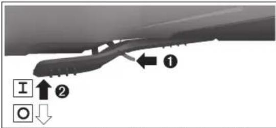
Switching On/Off
To start the power tool, push the unlocking lever (7) forwards and then push the on/off switch (6) up.
To switch off the power tool, release the on/off switch (6).
Always check abrasive tools before using them. The abrasive tool must be fitted properly and be able to move freely. Carry out a test run for at least one minute with no load. Do not use abrasive tools that are damaged, run untrue or vibrate during use. Damaged abrasive tools can burst apart and cause injuries.
Maintenance and Service
Maintenance and Cleaning
- Remove the battery from the power tool before carrying out work on the power tool (e.g. maintenance, changing tool, etc.). The battery should also be removed for transport and storage. There is risk of injury from unintentionally pressing the on/off switch.
To ensure safe and efficient operation, always keep the power tool and the ventilation slots clean.
Store and handle the accessories carefully.
After-Sales Service and Application Service
Our after-sales service responds to your questions concerning maintenance and repair of your product as well as spare parts. You can find explosion drawings and information on spare parts at: www.bosch-pt.com
The Bosch product use advice team will be happy to help you with any questions about our products and their accessories.
In all correspondence and spare parts orders, please always include the 10-digit article number given on the nameplate of the product.
Malaysia
Robert Bosch Sdn. Bhd.(220975-V) PT/SMY
No.8A,Jalan 13/6
46200 Petaling Jaya
Selangor
Tel.: (03) 79663194
Toll-Free: 1800 880188
Fax: (03) 79583838
E-Mail: kiathoe.chong@my.bosch.com
www.bosch-pt.com.my
You can find further service addresses at:
www.bosch-pt.com/serviceaddresses
Transport
The recommended lithium-ion batteries are subject to legislation on the transport of dangerous goods. The user can transport the batteries by road without further requirements.
When shipping by third parties (e.g.: by air transport or forwarding agency), special requirements on packaging and labelling must be observed. For preparation of the item being shipped, consulting an expert for hazardous material is required.
Dispatch battery packs only when the housing is undamaged. Tape or mask off open contacts and pack up the battery in such a manner that it cannot move around in the packaging. Please also observe the possibility of more detailed national regulations.
Disposal

Power tools, rechargeable batteries, accessories and packaging should be sorted for environmental-friendly recycling.
Do not dispose of power tools and batteries/re-chargeable batteries into household waste!
Battery packs/batteries:
Li-ion:
Please observe the notes in the section on transport (see "Transport", page 17).
Français
Protection anti-redemarrage
Robert Bosch Morocco SARL
53, Rue Lieutenant Mahmoud Mohamed
20300 Casablanca
Tel.: +212529314327
E-Mail: sav.outillage@ma.bosch.com
www.bosch-pt.com/serviceaddresses
Transport
www.bosch-pt.com/serviceaddresses
Transporte
Calle Robert Bosch No. 405
C.P. 50071 Zona Industrial, Toluca - Estado de Mexico
Tel.: (52) 55 528430-62
Tel.: 8006271286
Rebarbadora GWS 18V-10 P GWS 18V-10 P
Rebarbadora GWS 18V-10 P GWS 18V-10 P
Carregadores recomendados GAL 18...
GAX 18...
GAL 36.
GAL 18...
GAX 18...
GAL 36
www.bosch-pt.com/serviceaddresses
Transporte
www.bosch-pt.com/serviceaddresses
搬运
www.bosch-pt.com/serviceaddresses
搬運
"w" "w" w"w" w"w" w"w" w"w" w"w" w"w" w"w" w"w" w"w" w"w" w"w" w"w" w"w" w"w" w"w" w"w" w"w" w"w" w"w" w"w" w"w" w"w" w"w" w"w" w"w" w'
aannnnnnae
nnaunnuulnaaauuaanuau
a 101wauu uuuuuaaunuauuauuauuauuauuauuauuauuauuauuauuauuauuauuauuauuauuauuauuauuauuuuuuuuuuuuuuuuuuuuuuuuuuuuuuuuuuuuuuuuuuuuuuuuuuuuuuuuuuuuuuuuuuuuuuuuuuuuuuuuuuuuuuuuuuuuuuuuuuuuuuuuuuuuuuuuuuuuuuuuuuuuuuuuuuuuuuuuuuuuuuuuuuuuuuuuuuuuuuuuuuuuuuuuuuuuuuuuuUU
aunnnaananaananaananaananaananaananaananaananaananaananaananaananaananaananaananaananaananaananaananaananaananaananaananaananaananaananaananaananaananaananaananaananaananaananaananaananaananaananaananaananaananaananaananaananaananaananaananaananaananaananaanaraannnnnnnnnnnnnnnnnnnnnnnnnnnnnnnnnnnnnnnnnnnnnnnnnnnnnnnnnnnnnnnnnnnnnnnnnnnnnnnnnnnnnnnnnnnnnnnnnnnnnnnnnnnnnnnnnnnnnnnnnnnnnnnnnnnnnnnnnnnnnnnnnn
nnaaannnnnuuulw
Jauuuaaunluiuunnueanrnnnnae
nannnnn nnnnnnnnnnnnnnnnnnnnnnnnnnnnnnnnnnnnnnnnnnnnnnnnnnnnnnnnnnnnnnnnnnnnnnnnnnnnnnnnnnnnnnnnnnnnnnnnnnnnnnnnnnn
aunnnnnae aannnnnne
a 1
aalwauanunannnnae wuonnnnnaaennnnn nn nnnnnnnnnnnnnnnnnnnnnnnnnnnnnnnnnnnnnnnnnnnnnnnnnnnnnnnnnnnnnnnnnnnnnnnnnnnnnnnnnnnnnnnnnnnnnnnnnnnnnnnnn
nnaananaananaananaananaananaananaananaananaananaananaananaananaananaananaananaananaananaananaananaananaananaananaananaananaananaananaananaananaananaananaananaananaananaananaananaananaananaananaananaananaananaananaananaananaananaananaananaananaananaananaanaraannnnnnnnnnnnnnnnnnnnnnnnnnnnnnnnnnnnnnnnnnnnnnnnnnnnnnnnnnnnnnnnnnnnnnnnnnnnnnnnnnnnnnnnnnnnnnnnnnnnnnnnnnnnnnnnnnnnnn
A
nnuovnuuuvnuuuvnuuuvnuuuvnuuuvnuuuvnuuuvnuuuvnuuuvnuuuvnuuuvnuuuvnuuuvnuuuvnuuuvnuuuvnuuuvnuuuvnuuuvnuuuvnuuuvnuuuvnuuuvnuuuvnuuuvnuuuvnuuuvnuuuvnuuuvnuuuvnuuuvnuuuvnuuuvnuuuvvu
1 1
Jauunrnnnnaeunrnnnnae nannnnnnae
- 1
aunnnaunu uunnnnuaanuunn nannnnn nn nnnnnnnnnnnnnnnnnnnnnnnnnnnnnnnnnnnnnnnnnnnnnnnnnnnnnnnnnnnnnnnnnnnnnnnnnnnnnnnnnnnnnnnnnnnnnnnnnnnnnnnnnnnnnnnnnnnnnnnnnnnnnnnnnnnnnn
yauuunnuuun uanlauuunnun
nnaaalw waaanannnnnnae aen nnnnnae nnne anennnne nnnnne nnnnne nnnnne nnnnne nnnnne nnnnne nnnnne nnnnne nnnnne nnnnne nnnnne nnnnne nnnnne nnnnne nnnnne nnnnne nnnnne nnnnne nnnnne nnnnne nnnnne nnnnne nnnnne nnnnne nnnnne nannnee
nnaaannnnnne aolwn
aunnnnnaanannnnn nnnnnn nn nnnnnn nnnnnn nnnnnn
aaiiiaaiinaiinaiinaiinaiinaiinaiinaiinaiinaiinaiinaiinaiinaiinaiinaiinai
82|n
nauuunnuuuvu wuuuunnuuunnu uuuu uuuuulwuuu uuuuuuuuuuuuuuuuuuuuuuuuuuuuuuuuuuuuuuuuuuuuuuuuuuuuuuuuuuuuuuuuuuuuuuuuuuuuuuuuuuuuuuuuuuuuuuuuuuuuuuuuuuuuuuuuuuuuuuuuuuuuuuuuuuuuuuuuuuuuuuuuuuuuuuuuuuuuuuuuuuuuuuuuuuuuuuuuuuuuuuuuuuuuuuuuuuuuuuuuuUU
aannnnae aanennnnnne anen nnnnnnne ane ane ane ane ane ane ane ane ane ane ane ane ane ane ane ane ane ane ane ane ane ane ane ane ane ane ane ane ane ane ane ane ane ane ane ane ane ane
Uunnnnnaaaln nnnnnaan ane annnnnnaaannnnaaannnnaaannnnaaannnnaaannnnaaannnnaaannnnaaannnnaaannnnaaannnnaaannnnaaannnnaaannnnaaannnnaaannnnaaannnnaaannnnaaannnnaaannnnaaannnnaaannnnaaannnnaaannnnaaannnnaaannnnaaennnnaaannnnaaannnnaaannnnaaannnnaaannnnaaannnnaaannnnaaannnnaaannnnaaannnnaaannnnaaannnnaaannnnaaannnnaaannnnaaannnnaaannnnaaannnnaaannnnaaannnnaaannnnaaannnnaaannnnaaannnnaa annnnnnnnnnnnnnnnnnnnnnnnnnnnnnnnnnnnnnnnnnnnnnnnnnnnnnnnnnnnnnnnnnnnnnnnnnnnnnnnnnnnnnnnnnnnnnnnnnnnnnnnnnnnnnnnnnnnnnnnnnnnnnnnnnnnnnnnnnnn
y
I 1
nnaaennnnnnaeannne
nnnnnnnnnnnnnnnnnnnnnnnnnnnnnnnnnnnnnnnnnnnnnnnnnnnnnnnnnnnnnnnnnnnnnnnnnnnnnnnnnnnnnnnnnnnnnnnnnnnnnnnnnnnnnnnnnnnnnnnnnnnnn
1nnaaalwnnnnnaaaanennnnae
wulwunwunwunwunlwnu wunlwnu wunlwnu wunlwnu wunlwnu wunlwnu wunlwnu wunlwnu wunlwnu wunlwnu wunlwnu wunlwnu wunlwnu wunlwnu wunlwnu wunlwnu wunlwnu wunlwnu wunlwnu wunlwnu wunlwnu
nnaaannnnnnaanennnnnnaanannnnnnaanannnnnnaanannnnnnaanannnnnnaanannnnnnaanannnnnnaanannnnnnaanannnnnnaanannnnnnaanannnnnnaanannnnnnaanannnnnnaanannnnnnaanannnnnnaanannnnnnaanannnnnnaanannnnnnaanannnnnnaanannnnnnaanannnnnnaanennnnnnaanannnnnnaanannnnnnaanannnnnnaanannnnnnaanannnnnnaanannnnnnaanannnnnnaanannnnnnaanannnnnnaanannnnnnaanannnnnnaanannnnnnaanannnnnnaanannnnnnaanannnnnnaanannnnnnaanannnnnnaanannnnnna
T
aovvulwovnwnnnnannnnnnae nnuuauuunnuuauuauuuuauu uuaa uuaa uuaa uuaa uuaa uuaa uuaa uuaa uuaa uuaa uuaa uuaa uuaa uuaa uuaa uuaa uuaa uuaa uuaa uuaa uuaa uuaa uuaa uuaa uuaa uuaa uuaa uuaa uuaa uuaa uuaa uuaa uuaa uuaa
aannnnnnaanennnnnnnnnnnnnnnnnnnnnnnnnnnnnnnnnnnnnnnnnnnnnnnnnnnnnnnnnnnnnnnnnnnnnnnnnnnnnnnnnnnnnnnnnnnnnnnnnnnnnnnnnnnnnnnnnnnnnnnnnnnnnnnnnnnnnnnnnn
WuWuWuWuWuWuWuWuWuWuWuWuWuWuWuWuWuWuWuWuWuWuWuWuWuWuWuWuWuWuWuWuWuWuWuWuWuWuWuWuWuWuWuWuWuWuWuWuWuWuWwU WwUwUwUwUwUwUwUwUwUwUwUwUwUwUwUwUwUwUwUwUwUwUwUwUwUwUwUwUwUwUwUwUwUwUwUwUwUwUwUwUwUwUwUwUwUwUwUwUwUwUw
Liuuunwaiyaoalwnnuynauanwu uunnnaaannnnn nn nnnnnnnnnnnnnnnnnnnnnnnnnnnnnnnnnnnnnnnnnnnnnnnnnnnnnnnnnnnnnnnnnnnnnnnnnnnnnnnnnnnnnnnnnnnnnnnnnnnnnnnnnnnnnnnnnnnnnnnnnnnnnnnnnnnnnn
lunuununununununununununununununununununununununununununununununununununununununununununununununununununununun
A
aunnnnnaanannnnnnnnnnnnnnnnnnnnnnnnnnnnnnnnnnnnnnnnnnnnnnnnnnnnnnnnnnnnnnnnnnnnnnnnnnnnnnnnnnnnnnnnnnnnnnnnnnnnnnnnnnnnnnnnnnnnnnnnnnnnnnnnnnnnnnnnnnnnnnnnnnnnnnn nn
aunnnnnaannnnnnnnnnnnnnnnnnnnnnnnnnnnnnnnnnnnnnnnnnnnnnnnnnnnnnnnnnnnnnnnnnnnnnnnnnnnnnnnnnnnnnnnnnnnnnnnnnnnnnnnnnnnnnnnnnnnnnnnnnnnnnnnnnnnnnnnnnnnnnnnnnnnnnnnnnnnnnnnnn
aunnnnnaannnnn nn nnnnnnnnnnnnnnnnnnnnnnnnnnnnnnnnnnnnnnnnnnnnnnnnnnnnnnnnnnnnnnnnnnnnnnnnnnnnnnnnnnnnnnnnnnnnnnnnnnnnnnnnnnnnnnnnnnnnnnnnnnnnn
Haaanannnnaaunnnnnae anannnnae aannnnnnae nnnnnnnnnnnnnnnnnae annnnnnnnnnnnnnnne nnnnnnnnnnnnnnne nnnnnnnnnnnnnnne nnnnnnnnnnnnnnne nnnnnnnnnnnnne nannnnnnnnnne nannnnnnnnnne nannnnnnnnnne nannnnnnnnnne nannnnnnnne nannnnnnnne nannnnnnnne nannnnnnnne nannnnnnnne nannnnnne nannnnnne nannnnnne nannnnnne nannnnnne nannnnnne nannnnnne nannnnnne nannnnnne nannnnnne nannnnnne nannnnnne nannnnnne nannnnnne nannnnnne nannnnnne nannnnnne nannnnnne nannnnnne nannnnnne nenn
aunnnnnaannnnnnnnnnnnnnnnnnnnnnnnnnnnnnnnnnnnnnnnnnnnnnnnnnnnnnnnnnnnnnnnnnnnnnnnnnnnnnnnnnnnnnnnnnnnnnnnnnnnnnnnnnnnnnnnnnnnnnnnnnnnnnnnnnnnnnnnnnnnnnnnnnnnnnnnnnnnnnnnnnnnnnnnnnnnn nn nannnannnannnannnannnannnannnannnannnannnannnannnannnannnannnannnannnannnannnannnannnannnannnannnannnannnannnannnannnannnannnannnannnannnannnannnannnannnannnannnannnannnannnannnannnannnannnannnannnannnann
nnaaayinaeavnyaaanannnnn nnnnnnnnnnnnnnnnnnnnnnnnnnnnnnnnnnnnnnnnnnnnnnnnnnnnnnnnnnnnnnnnnnnnnnnnnnnnnnnnnnnnnnnnnnnnnnnnnnnnnnnnnnnnnnnnnnnnnnnnnnnnnnnnnn nn
mnnn nnnnnnnnnnnnnnnnnnnnnnnnnnnnnnnnnnnnnnnnnnnnnnnnnnnnnnnnnnnnnnnnnnnnnnnnnnnnnnnnnnnnnnnnnnnnnnnnnnnnnnnnnnnnnnnnnnnnnnnnnnnnnnnnnnnnnnnnnnnnnnnnnnnnnnnnnnnnnnnnnnnn nn nnu nnu nnu nnu nnu nnu nnu nnu nnu nnu nnu nnu nnu nnu nnu nnu nnu nnu nnu nnu nnu nnu nnu nnu nnu nnu nnu nnu nnu nnu nnu nnu nnu nnu nnu nnu nnu nnu nnu nnu nnu nnu nnu nnu nnu nnu nnu nnu nnu nnu n\n
ywnnnaaunnnnnae
nnaaannnnnnae nnnnne aennnnne
Mnannnnnnaaee 1
JUULUHUAUauuuaanwnannnnn uonannnnn
aunnnaalwwnnnnnaanana nannnna
ywnnnn nn nnnnnnnnnnnnnnnnnnnnnnnnnnnnnnnnnnnnnnnnnnnnnnnnnnnnnnnnnnnnnnnnnnnnnnnnnnnnnnnnnnnnnnnnnnnnnnnnnnnnnnnnnnnnnnnnnnnnnnnnnnnnnnnnnnnnnnnnn
nannnnnaaanennnnnnnnnnnnnnnnnnnnnnnnnnnnnnnnnnnnnnnnnnnnnnnnnnnnnnnnnnnnnnnnnnnnnnnnnnnnnnnnnnnnnnnnnnnnnnnnnnnnnnnnnn
aunnnaeauu uuaanennnnnnaeauu 1 nannnnnnaeauu naa aannnnnnaeauu nnnnnaeauu nnnnnaeauu nnnnnaeauu nnnnnaeauu nnnnnaeauu nnnnnaeauu nnnnnaeauu nnnnnaeauu nnnnnaeauu nnnnnaeauu nnnnnaeauu nnnnnaeauu nnnnnaeauu nnnnnaeauu nnnnnnaeauu nnnnnaeauu nnnnnaeauu nnnnnaeauu nnnnnaeauu nnnnnaeauu nnnnnaeauu nnnnnaeauu nnnnnaeauu nnnnnaeauu nnnnnaeauu nnnnnaeauu nnnnnaeauu nnnnnaeauu nnnnnaee
a
1 1
JauuuaaunuuuuaaunuuuuuuuuuuuuuuuuuuuuuuuuuuuuuuuuuuuuuuuuuuuuuuuuuuuuuuuuuuuuuuuuuuuuuuuuuuuuuuuuuuuuuuuuuuuuuuuuuuuuuuuuuuuuuuuuuuuuuuuuuuuuuuuuuuuuuuuuuuuuuuuuuuuuuuuuuuuuuuuuuuuuuuuuuuuuuuuuuuuuuuUU
84|n
ywnnnaaennnnnnaaannnnnnae
nunnnnnnnnnnnnnnnnnnnnnnnnnnnnnnnnnnnnnnnnnnnnnnnnnnnnnnnnnnnnnnnnnnnnnnnnnnnnnnnnnnnnnnnnnnnnnnnnnnnnnnnnnnnnnnnnnnnnnnnnnnnnnnnnnnnnnnn
nnaaannnnnnaanennnnnnae annnnnnaa
Iannnnnnaaunnnnnnnnnnnnnnnnnnnnnnnnnnnnnnnnnnnnnnnnnnnnnnnnnnnnnnnnnnnnnnnnnnnnnnnnnnnnnnnnnnnnnnnnnnnnnnnnnnnnnnnnnnnnnnnnnnnnnnnnnnnnnnnnnnnnnnnnnnnnnnnnnnnnnnnnnnnnnnnnnnnnnnnnnnnn nn nannnannnannnannnannnannnannnannnannnannnannnannnannnannnannnannnannnannnannnannnannnannnannnannnannnannnannnannnannnannnannnannnannnannnannnannnannnannnannnannnannnannnannnannnannnannnannnannnannnannnann
yannnnnnaananaanrnuanrnuanrnuanrnuanrnuanrnuanrnuanrnuanrnuanrnuanrnuanrnuanrnuanrnuanrnuanrnuanrnuanrnuanrnuanrnuanrnuanrnuanrnuanrnuanrnuanrnuanrnuanrnuanrnuanrnuanrnuanrnuanrnuanrnu
nannnnnnaaennnnnnae nnnnnnnae nnne nnnnnnnae nnnnnnnae nnnnnnnae nnnnnnnae nnnnnnnae nnnnnnnae nnnnnnnae nnnnnnnae nnnnnnnae nnnnnnnae nnnnnnnae nnnnnnnae nnnnnnnae nnnnnnnae nnnnnnnae nnnnnnnae nnnnnnnae nnnnnnnnae nnnnnnnae nnnnnnnae nnnnnnnae nnnnnnnae nnnnnnnae nnnnnnnae nnnnnnnae nnnnnnnae nnnnnnnae nnnnnnnae nann
nivnnaanrnnnnaaannnnnnae nnnn nn nnnnnnnnnnnnnnnnnnnnnnnnnnnnnnnnnnnnnnnnnnnnnnnnnnnnnnnnnnnnnnnnnnnnnnnnnnnnnnnnnnnnnnnnnnnnnnnnnnnnnnnnnnnnnnnnnnnnnnnnnnnn
nunuauuuvnuuunauuuuauuun
nni nnnnnnnnnnnnnnnnnnnnnnnnnnnnnnnnnnnnnnnnnnnnnnnnnnnnnnnnnnnnnnnnnnnnnnnnnnnnnnnnnnnnnnnnnnnnnnnnnnnnnnnnnnnnnnnnnnnnnnnnnnnnnnnnnnnnnnnnnnnnnnn
Huaaunuauanwanaanwaaanwnan
nnnnnnnnnnnnnnnnnnnnnnnnnnnnnnnnnnnnnnnnnnnnnnnnnnnnnnnnnnnnnnnnnnnnnnnnnnnnnnnnnnnnnnnnnnnnnnnnnnnnnnnnnnnnnnnnnnnnnnnnnnnnnnnnnnnnnnnnnnnnnnnnn
wauuuaaunan 2 wuuuauuunu uuuuauuauu uuuuauuunu uuuuuuuuuuuuuuuuuuuuuuuuuuuuuuuuuuuuuuuuuuuuuuuuuuuuuuuuuuuuuuuuuuuuuuuuuuuuuuuuuuuuuuuuuuuuuuuuuuuuuuuuuuuuuuuuuuuuuuuuuuuuuuuuuuuuuuuuuuuuuuuuuuuuuuuuuuuuuuuuuuuuuuuuuuuuuuuuuuuuuuuuuuuuuuuuuuuuuuuUU
WuWuWuWuWuWuWuWu
In LED
WuTuH: WnTuUuuuunnnnueuuu uuuuuuuu uuuuuuuuuuuuuuuuuuuuuuuuuuuuuuuuuuuuuuuuuuuuuuuuuuuuuuuuuuuuuuuuuuuuuuuuuuuuuuuuuuuuuuuuuuuuuuuuuuuuuuuuuuuuuuuuuuuuuuuuuuuuuuuuuuuuuuuuuuuuuuuuuuuuuuuUU
nnu nnuunnuuunnuuunnuuunnuu (1) nuu uuuuuuuuuuuuuuuuuuuuuuuuuuuuuuuuuuuuuuuuuuuuuuuuuuuuuuuuuuuuuuuuuuuuuuuuuuuuuuuuuuuuuuuuuuuuuuuuuuuuuuuuuuuuuuuuuuuuuuuuuuuuuuuuuuuuuuuuuuuuuuuuuuuuuuuuuuuuuuuuuuuuuuuuuuuuuuuuuuuuuuuuuuuuuuuuuuuuuuuuuUU
aunnuuunnuuunnuuunnuu (11) lu anuue nauuuvnuuunnuu (1) uuuu uuuuuuuuuuuuuuuuuuuuuuuuuuuuuuuuuuuuuuuuuuuuuuuuuuuuuuuuuuuuuuuuuuuuuuuuuuuuuuuuuuuuuuuuuuuuuuuuuuuuuuuuuuuuuuuuuuuuuuuuuuuuuuuuuuuuuuuuuuuuuuuuuuuuuuuuuuuuuuuuuuuuuuuuuuuuuuuuuuuuuuuuuuuuuuuuuuuuuuuuuUU
unnuuunnu (11) uanunnuuunu
nVvovnuu (11) vovnuuulau nnuuuaan (1) uuu! uauauauu uuu uauuauu uuuuuuuuuuuuuuuuuuuuuuuuuuuuuuuuuuuuuuuuuuuuuuuuuuuuuuuuuuuuuuuuuuuuuuuuuuuuuuuuuuuuuuuuuuuuuuuuuuuuuuuuuuuuuuuuuuuuuuuuuuuuuuuuuuuuuuuuuuuuuuuuuuuuuuuuuuuuuuuuuuuuuuuuuuuuuuuuuuuuuuuuuuuuuuuuuuuuuuuuuUU
WuWu: auaaunnuuuu (11)
nuiuulauw: nuiu uunuunuunuunu u
n
nnaananaananaananaananaananaananaananaananaananaananaananaananaananaananaananaananaananaananaananaananaananaananaananaananaananaananaananaananaananaananaananaananaananaananaananaananaananaananaananaananaananaananaananaananaananaananaananaananaananaananaanaraannnnnnnnnnnnnnnnnnnnnnnnnnnnnnnnnnnnnnnnnnnnnnnnnnnnnnnnnnnnnnnnnnnnnnnnnnnnnnnnnnnnnnnnnnnnnnnnnnnnnnnnnnnnnnnnnnnnnn
nnaaunnu (10) nnaanannnnnnae annnnae Bosc hnnnnnnnnnnnnnnnnnnnnnnnnnnnnnnnnnnnnnnnnnnnnnnnnnnnnnnnnnnnnnnnnnnnnnnnnnnnnnnnnnnnnnnnnnnnnnnnnnnnnnnnnnn
nnuuunnuuunnuun
un (bonded abrasives) 12
W
(12)wuu (11)
Huaanquaaunnnnne
(32)nuu (11)
nnaeannua
mwnnnnnaa (24) wannnu/
wunnu/nuannu/nuannu/nuannu (23) 1
(23) (8)/(9)
nunnnn nnnn nn nnnnnnnnnnnnnnnnnnnnnnnnnnnnnnnnnnnnnnnnnnnnnnnnnnnnnnnnnnnnnnnnnnnnnnnnnnnnnnnnnnnnnnnnnnnnnnnnnnnnnnnnnnnnnnnnnnnnnnnnnnnnnnnnnnnnnnnnnnnnnnnn
(8)/(9)
aivnnaalnnnnaaunnnae (8)/(9) 000000000000000000000000000000000000000000000000000000000
Vibration
(9)
yuaanlunuynulanaauna
n
nannnnnnnnnnnnnnnnnnnnnnnnnnnnnnnnnnnnnnnnnnnnnnnnnnnnnnnnnnnnnnnnnnnnnnnnnnnnnnnnnnnnnnnnnnnnnnnnnnnnnnnnnnnnnnnnnnnnnnnnnnnnnnnnnnnnnnnnnnnnnnnnnnnnnnnnnnnnnnnnnnnn
y
nnaaannnnn (22) naanennnnnnnnnnnnnnnnnnnnnnnnnnnnnnnnnnnnnnnnnnnnnnnnnnnnnnnnnnnnnnnnnnnnnnnnnnnnnnnnnnnnnnnnnnnnnnnnnnnnnnnnnnnnnnnnnnnnnnnnnnnnnnnnnnnnnnnnnnnnnn
nauunuunnuunuaanuunuuuau
7nna/naaunannnnn 125uu.
ynuuynnuuynnuynnuynnuynnuynnuynnuynnuynnuynnuynnuynnuynnuynnuynnuynnuynnuynnuynnuynnuynnuynnuynnuynnuynnuynnuynnuynnuynnuynnuynnuynnuynnuynnuynnuynnuynnuynnuynnuynnuynnuynnuynnuynnuynnuynnuynnuynnuynnuynnuynnuyn\n
nnuuunnnnnnnnnnnnnnnnnnnnnnnnnnnnnnnnnnnnnnnnnnnnnnnnnnnnnnnnnnnnnnnnnnnnnnnnnnnnnnnnnnnnnnnnnnnnnnnnnnnnnnnnnnnnnnnnnnnnnnnnnnnnnnnnnnnnnnnnnnnnnnnnnnnnn
120 125 u.
10000000000000000000000000000000000000000000000
(20)
1 20 (20)
- 1nunnnnnaa/na lnlnnnnnaaennn nnnn (20).
nauanunu (3) wu
nuunnuov annu
nuuunnuu (20)
nuuunnuu uuuu
uuuuuuuuuuuuuuuuuuuuuuuuuuuuuuuuuuuuuuuuuuuuuuuuuuuuuuuuuuuuuuuuuuuuuuuuuuuuuuuuuuuuuuuuuuuuuuuuuuuuuuuuuuuuuuuuuuuuuuuuuuuuuuuuuuuuuuuuuuuuuuuuuuuuuuuuuuuuuuuuuuuuuuuuuuuuuuuuuuuuuuuuuuuuuuuuuuUU
nnnnn nnnn nn nnnn nnnn nnnn nnnn nnnn nnnn nnnn nnnn nnnn nnnn nnnn nnnn nnnn nnnn nnnn nnnn nnnn nnnn nnnn nnnn nnnn nnnn nnnn nnnn nnnn nnnn nnnn nnnn nnnn nnnn nnnn nnnn nnnn nnnn nn
- 1nnn nnnnnnnnnnnnnnnnnnnnnnnnnnnnnnnnnnnnnnnnnnnnnnnnnnnnnnnnnnnnnnnnnnnnnnnnnnnnnnnnnnnnnnnnnnnnnnnnnnnnnnnnnnnnnnnnnnnnnnnnnnnnnnnnnnnnnnnnnnnnnnnnnnnnnn nn
nuaaannnnnnaanennnnaanennnnnnnnnnnnnnnnnnnnnnnnnnnnnnnnnnnnnnnnnnnnnnnnnnnnnnnnnnnnnnnnnnnnnnnnnnnnnnnnnnnnnnnnnnnnnnnnnnnnnnnnnnnnnnnnnnnnnnnnnnnnnnnnnnnnnnnnnnnnnnnnnnnnnnnnnnnnn nn nannnnuuauuuuauuuuuuuuuuuuuuuuuuuuuuuuuuuuuuuuuuuuuuuuuuuuuuuuuuuuuuuuuuuuuuuuuuuuuuuuuuuuuuuuuuuuuuuuuuuuuuuuuuuuuuuuuuuuuuuuuuuuuuuuuuuuuuuuuuuuuuuuuuuuuuuuuuuuuuuuuuuuuuuuuuuuuuuuuuuuuuuUU
nnsnnnnnnnnnnnnnnnnnnnnnnnnnnnnnnnnnnnnnnnnnnnnnnnnnnnnnnnnnnnnnnnnnnnnnnnnnnnnnnnnnnnnnnnnnnnnnnnn
- 111 (11).
nnaananaananaananaananaananaananaananaananaananaananaananaananaananaananaananaananaananaananaananaananaananaananaananaananaananaananaananaananaananaananaananaananaananaananaananaananaananaananaananaananaananaananaananaananaananaananaananaananaananaananaanaraannnnnnnnnnnnnnnnnnnnnnnnnnnnnnnnnnnnnnnnnnnnnnnnnnnnnnnnnnnnnnnnnnnnnnnnnnnnnnnnnnnnnnnnnnnnnnnnnnnnnnnnnnnnnnnnnnnn
n
(24)
y
aannnnnnae
uuannau (26) uuaaunu
uunnnn nn nnnnnnnnnnnnnnnnnnnnnnnnnnnnnnnnnnnnnnnnnnnnnnnnnnnnnnnnnnnnnnnnnnnnnnnnnnnnnnnnnnnnnnnnnnnnnnnnnnnnnnn
1nnuuunnuuunnuuunnuuunnuuunnuuuuuuuuuuuuuuuuuuuuuuuuuuuuuuuuuuuuuuuuuuuuuuuuuuuuuuuuuuuuuuuuuuuuuuuuuuuuuuuuuuuuuuuuuuuuuuuuuuuuuuuuuuuuuuuuuuuuuuuuuuuuuuuuuuuuuuuuuuuuuuuuuuuuuuuuuuuuuuuuuuuuuuuuuuuuuuuuuuuuuuuuuuuuuuuuuuuuuuuuuUU
mnnnnuuunnuu/uuuunnuuun nannnna (23)
aunnnnnaeannnnne nnnnne annnnnne
WJWJWJWJWJWJWJWJWJWJWJWJWJWJWJWJWJWJWJWJWJWJWJWJWJWJWJWJWJWJWJWJWJWJWJWJWJWJWJWJWJWJWJWJWJWJWJWJWJWJW
a. 1. 1. 1. 1. 1. 1. 1. 1. 1. 1. 1. 1. 1. 1. 1. 1. 1. 1. 1. 1. 1. 1. 1. 1. 1. 1. 1. 1. 1. 1. 1. 1. 1. 1
Iunnnnnaa aan mnnnnnnnnnnaeauu Iuuu uannnnnnaa an annnnnnnnaa an nnnnnaa nn nnnnnaa an nnnnnaa an nnnnnaa an nnnnnaa an nnnnnaa an nnnnnaa an nnnnnaa an nnnnnaa an nnnnnaa an nnnnnaa an nnnnnaa an nnnnnaa an nnnnnaa an nnnnnaa an nnnnnaa an nnnnnaa an nnnnnaa an nnnnnee
92|m
#
Wu Huaan Jnauuun 17 17 17 17 17 17 17 17 17 17 17 17 17 17 17 17 17 17 17 17 17 17 17 17 17 17 17 17 17 17 17 17 17 17
mnnnnnns
nunwnnnnnaaannnnnnnn
mnnnunununnnnnnnnnnnaa nannnna (23)
www.bosch-pt.com/serviceaddresses
#
山
T

Wnwnnnn nn nnnnnnnnnnnnnnnnnnnnnnnnnnnnnnnnnnnnnnnnnnnnnnnnnnnnnnnnnnnnnnnnnnnnnnnnnnnnnnnnnnnnnnnnnnnnnnnnnnnnnnnnnnnnnnnnnnnnnnnnnnnnnnnnnnnnnnnnnnnnnnnnnnnnnnnnnnnnn
ywnuynnnynnnnynnnnynnnnynnnnynnnnynnnnynnnnynnnnynnnnynnnnynnnnynnnnynnnnynnnnynnnnynnnnynnnnynnnnynnnnynnnnynnnnynnnnynnnnynnnnynnnnynnnnynnnnynnnnynnnnynnnnynnnnynnnnynnnnynn
wuaaW/uWua
aun laan:
nun 93)
Bahasa Indonesia
Keselamatan personnel

Pakailah kaca mata pelinding.
Arkadia Green Park Tower G-7th floor
Ji. Let. Jend. TB. Simatupang Kav.88
Jakarta 12520
Tel.: (021) 3005 5800
104 | Tieng Viet
Fax: (021) 3005 5801
E-Mail: boschpowertools@id.bosch.com
www.bosch-pt.co.id
www.bosch-pt.com/serviceaddresses
Transpor
Canh Bao An Toan cho May Mai Hinh Goc
Cac canh bao An toan chung cho cac thao tac Mai, Phun cat, Chai bong bang Kim loai hoac Cat bang Rap
Dung cu dien cam tay nay co chu c nang nu' mot may mai, may phun cat, ban chai danh bong kim loai hoac dung cu cat. Hay doc toan bo cac canh bao an toan, huong dan, hinh anh va thong so ky thuat duoc cung cap cho dung cu dien cam tay nay. Khong tuan thu moi huong dan duoc liet ke duoi day co the bi dien giat, gay chay va /hay bi thuong tat nghiem strong.
Khong nen thu cien cac thao tac nu'danh bong bang dung cu dien cam tay nay. Cac thao tac khong duoc thi et ke cho dung cu dien
106 | Tiěng Viét
cām tay nay có thegay nguy hiēm hoac gay tón thuong cho con nguòi.
Khong duoc su dung cac phu kien khong duoc thiiet ke rieng va khuyen dung boi nha san xuat dung cu. Bovi phiu kien co the gan duoc voi dung cu dien cam tay cua ban, nhung no khong dam bao hoat dong an toan.
Toc do dinh muc cua phu kien toi thieu thai bang toc do toi da duoc ghi tren dung cu dien cam tay. Cac phu kien chay nanh hon toc do dinh muc cua chung co the bi vao va vang ra.
▶Duong kinh ngoai va do day cua phu kien phai nam trong dinh muc concg suat cua dung cu dien cam lay cua ban. Khong the bao vhe hoac kiem soat phu hop cac phu kien sai kich co.
Lap ghep ta long cua cac phu kien thai hop voi dau ren truc chin cua may mai. Doi voicac phu kien duoc lap ghep bang cac bich, lo tam cua phu kien thai khit voi dong kinh dinh vi cua bich.Cac phu kien khong thai vovi cac phu kien cung ghep noi cua dung cu dien cam tay se lam mat can bang, rung lac qua muc va co the lam mat kiem soat.
Khong duoc su dung phu kien bi hong. Trucmian sur dung, can kiem tra ky cac vet nut va ran cua dia mai, cac vet ran nut, mon hoac mai mon qua muc cua tam dem, cac dau kim loai bi long hoac bi nut cua ban chai kim loai. Neu lam roi dung cu dien cam tay hoac phu kien, can kiem tra hong hoac thay the bang phu kien khong bi hong. Sau khi kiem tra va thay the phu kien, ban va ngu'o xung quanh dung phai tranh huong luoi bao cua cac phu kien xoay va khoi dong dung cu dien o toc do khong tai toi da trong vong mot phut. Cac phu kien bi hong thuong bi vo doi trong qua trinh chay thu nay.
Mac thiet bi bao ho ca nhan. Tuy thuoc vao tung cong viec, hy sur dung mat na, kinh bao ve hoac kinh an toan. Neu co, hay deo mat na chong bui, dung cu bao ve tai, gang tay va tap de lao dong co the ngan chan mat mai nh o hac cac manh vun cua phoi. Dung cu bao ve mat phai co kha nang ngan chan manh vban ra do cac thao tac khac nhau sinh ra. Mat na chong bui hoac mat na chong doc phai co kha nang loc cac tap chat do thao tac cua ban sinh ra. Viec tiep xuc lau voi tieng on qua cao co the lam giam thinh giac.
Hay cach ly nguoi xung quanh tranh xa khu vuc lam viec mot khoang cach an toan. Bat ky ai di vao khu vuc lam viec phai mac thiet bi bao ho cnan. Cac manh vo cua phi hoac cua phu kien bi vo co the vang ra ngoai khoi khu vuc lam viec va co the gay ton thuong.
Chi cam dung cu dien tai cac be mat cam nam co cach dien, khi thuc hiem mot thao tac tai vi tri ma phu kien cat co the tiep xuc voi day dien ngam. Viec tiep xuc "truc tiep" voi day co dien cung co the lam cho cac phan kim loai ho cua dung cu dien cam tay co dien va co the gay ra dien giat cho nguoi van hanh.
Tuyét doi khong de dung cu dien cam tay xuong dát cho toí khi phan quay cua thiet bi da dung hǎn. Phan phu kien quay co the ngoam be mát va kéo dung cu dien cam tay khoi tam kiem soát.
Khong duoc van hanh dung cu dien cam tay trong khi dang deo no tren nguoi. Viec vo tinh tiep xuc voi phan phy kiien quay co the ngoam quan ao cua ban, keo phy kiien ve phia cua ban.
Thuong xuyen ve sinh cac lo thong khi cua dung cu dien cam tay. Quat cua mo to se hut bui bān vao trong vo ngoai va viec tich tu qua muc mat kim loai co the gay ra cac rui ro dien giat.
Khong duoc van hanh dung cu dien cam tay gan cac vat lieu de chay. Cac tia la co the dot chay cac vat lieu do.
Khong duoc su dung cac phu kien can su dung cac dung dich lam ngloi. Viec su dung nuoc hoac cac dung dich lam ngloi khac co the gay ra dien giat.
Luc phan hoi va cac Canh bao Lien quan
Luc phan hoi la mot luc tac dong dot ngot len dia
quay, tam dem, ban chai hoac bat ky phi kien nao
khac bi ep hoac mai mon. Viec ep hoac mai mon
lam cho phan phi kien quay dung gap sau do gay
ra tac dong manh vao thiet bi dien cam tay khong kiem soat duoc theo huong nguc voi huong quay
cua phi kien tai diem lien ket.
Vidu, neu dia mai bi mai mon hoac ep boi phi ia
cong, MEP cua dia mai tiep xuc voi diem ep co the
tao ranh be mat cua vat lieu lam cho dia mai nhorao
hoac va dap. Dia mai co the nhay ve phia hoac
nhay ra ngoai tu phi ngoi van hanh, tuy thuoc
vao huong di chuyen cua dia mai tai diem ep. Cac dia mai cung co the bi vo trong cac truong hop nay. Luc phan hoi la do viec su dung sai va/hoac quy
trinh hoac dieu kien van hanh sai dung cu dien
caml tay va co the phong tranh bang cach ap dung
cac bien phap phong ngua phi hop duoc neu duoi day.
Gi chat dung cu dien cam tay va giu cho co the va tay cua ban chac chan cho phep ban chiu duoc cac luc phan hoi. Luon su dung tay cam phu, neu co, de kiem soat toi da luc phan hoi hoac luc momen xoan trong khi khoi dong. Nguoi van hanh co the kiem soat duoc cac luc momen xoan hoac luc phan hoi neu ap dung cac bian phap phong ngua phu hop.
Tuyét doi khong de tay gan phan phi quay. Phu kien co the tac dong lai tay cua ban.
Khong duoc dung tai noi dung cu dien cam tay di chuyen nu xay ra luc phan hoi. Luc phan hoi se day dung cu theo huong nguc voi huong di chuyen cua dia mai tai diem mai mon.
Su dung tam bao ve dac biet khi lam vic tai cac goc, canh sac v.v.v. Tranh lam nay va mai mon phu kien. Cac goc, canh sac hoac viec nay len co the mai mon phu kien quay va dan den mat kiem soat hoac day nguc lai.
Khong duoc lap them luoi cua go dang luoi cua xich hao luoi cua co rang. Cac luoi nhu vay co the tao luc phan hoi thuong xuyen va lam mat kiem soat.
Cac Canh bao An toan dang rieng cho cac thao tac Mai va Cat
Chi su dung cac loai dia duoc chi dinh cho dung cu dien cam tay cua ban va la chan bao vé rieng duoc thiet ké cho dia cat da chon. Cac loai dia khong duoc thiet ké cho dung cu dien cam tay nay co the khong duoc bao vé phu hop va khong an toan.
Bé māt mai消费品i mai lam giam truc tam phai duoc lap phia duoi phan phang cua vanh chan bao ve. Eia lap ghep khong dung cach chia ra khoi be māt消费品i vanh chan bao ve co the khong duoc bao ve phu hop.
Vanh chan bao vê phai duoc gán co dinh vao dung cu dien cam tay va dam bao su an toan tói da, sao cho phan dia hra huóng vé phia nguovi van hanh it nhát. Vanh bao vê giup bao vê nguovi van hanh tranh cac manh vio dia mai, tiep xuc do vo tinh voi dia mai hoac cac tia lura co the gay chay quan ao.
▶ Phai su dung cac dia mai duoc chi dinh rieng cho tung cong viec. Vi du: khong duoc mai bang canh cua dia cat. Cac dia cat bang nham chi duoc su dung cho mai MEP, cac luc bien tac dung vao cac dia cat nay co the lam chung bi vo.
Luon su dung cac bich dem dia khong bi hong dung kich co va hinh dang cho dia da chon cua ban. Cac bich dem dia phu hop do dia mai cho phep lam giam kha nang vo dia. Cac bich dem cho cac dia cat co the khac voi cac bich dem dia mai.
Khong duoc su dung cac dia da mai mon tucac dung cu dien lon hon. Dia danh rieng cho dung cu dien cam tan hon khong phu hopcho toc do cao hon cua dung cu dien nh o hon vaco the vo.
Cac Canh bao An toan Bó sung dang rieng cho cac thao tac Cat
Khong duoc lam ket dia cat hoac ty de qua luc. Khong duoc co gang kat sau qua muc. Viec tao ung suat qua muc len dia lam tang tai
và dé gay ra xo'an hoac ket dia trong khi cat va co the tao luc phan hoi hoac lam vā dia.
Khong duoc dung song song va phia sau dia quay. Khi dia, o vi tri vanh, dang di chuyen theo huong co the ban, luc phan hoi co the day dia quay va dia quay va dung cu truc tiep ve phia ban.
Khi dia bi ket hoac khi dung cat vi ly do nao do, hyayt nguon dung cu dien cam tay va giu co dinh thiet bi dien toi khi dia da dung quay hain. Tuyet doi khong co gang thao dia cat ra trong khi dia van dang quay neu khong luc phan hoi co the xay ra. Kiem tra va co bian phap khac phuc de loai bo nguyen nhan ket dia.
Khong duoc khoi dong lai thao tac kat khi bi ket trong phoi. De dia quay dat toc do cuc dai va can than khoi dong lai dong cat. Dia co the bi ket, nay len hoac tac dong tro lai neu khoi dong lai dung cu dien ket trong phoi.
Su dung cac tam do hoac thai kich co de glam thieu nguy co ep dia va luc phan hoi. Cac thai Ion thuong vong xuong duoi trong luong rieng cua chung. Can thai cac tam do phia duoi thai gan duong cat va gan canh cua thai ve ca hai phia cua dia cat.
Su dung bién phap an toan khac khi cat ranh vao cac vach hién co hoac cac khu vuc chan tuong. Dia cat nhoi len co the cat dut cac duong ong khi hoac nuoc, day dien hoac cac vat dung co the gay ra luc phan hoi.
Cac Canh bao An toan Bó sung dang rieng cho cac thao tac Mai
Khong duoc su dung dia mai qua kich co.
Tuan thu cac khuyen nghi cua nhà san xuat
khi chon dia mai. Dia mai lón hon vuot qua
kich co tām dem mai gay rnguy co xé rach va
co the gay mai mon, rach dia mai hoac luc phan
hói.
Cac Canh bao An toan Bó sung dang rieng cho cac thao tac Chai bóng
Can luu y rang cac soi tong hop day dien bi mac vao bian chai ngay ca khi van hanh binh thuong. Khong duoc keo qua cang day dien bang cach de qua tai vao bian chai Cac soi tong hop day dien co the dang than nhap vao quan ao mong va/hoac da.
Neu can phai su dung vanh chan bao ve de chai bong, khong duoc de dia dem kim loai hoac ban chai dinh vao vanh bao ve. Dia dem kim loai hoac ban chai co the bian ra do tai lam viec va cac luc ly tam.
Caccanh bao phu them

Hāy mang kinh bao hó.
Dung thiet bi do tim thich hop de xac dinh neu co cac cong trinh cong cong lap dat ngamstrong khu vu c lam viec hay lien he voi Cty cong trinh cong cong dia phuong de nho h tro. Dung cham duong dan dien co the gay ra hoa hoan va dien giat. Lam hu' hai duong dan khia ga co the gay no. Lam thung ong dan nuoc co the lam hu' hai tai san hay co the gay ra dien giat.
Khong duoc cham vao dia mai hay dia cat trucc khi cac dia nay da ngoi. Dia co the tro nen rat nong trong luc hoat dong.
Nha cong tac Tat/Mo ra va chuyen ve vj tri tat khi nguon dien cung cap bi ngat,vi du.,nhu khi rut ac quy.Cach nay de ngan su khoi dong lai khong duoc kiem soat.
Kep chat vatgia cong. Vat gia cong duoc kep bang mot thiet bi kep hay bang eto thi vu ng chac hon giu bang tay.
Trong truong hop pin bj hong hay su dung sai cach, hoi nuoc co the boc ra. Pin co the chay hoac no. Hay lam cho thong thoang khi va. trong truong hop bi dau thai nh o y te chu a tri. Hoi nuoc co the gay ngua he ho hap.
Khong duoc thao pin ra. Nguyen co bi chap mach.
Pin co the bi hu hai boi cac vat dung nhon nhu dinh hay tuoc-no-vit hoac boi cac tac dong luc tu ben ngoai. No co the dan toi doan mach nao bo va lam pin bi chay, boc khoi, phat no hoac qua nong.
Chi su dung pin trong cac san pham cua nha san xuat. Chi bang cach nay, pin se duoc bao vê tranh nguy co qua tai.
Bao vé pin khong de bi lam nong, vi du, chong de lau dai duoi anh nang gay gat, lua, chat ban, nuoc, va su am uot. Co nguy co no va chap mach.
Hang Bosch co cung cap loai may hut bui thich hop.
Bat dung cu dien cam
tay va dat no len poi
gia cng bang phan
truc cua mau dong.
Day nhe may toi cho an
vao vua thai, tuy theo
loai vat lieu gia cng
ma thich nghi.
www.bosch-pt.com/serviceaddresses
Vanhuyen
Pin Li-lon duoc khuyen nghi la doi tuong phai tuan theo cac qui dinh cua Phap Luat ve Hang Hoa Nguyen Hiem. Ngu di su dung co the van chuyen pin hop khoi bang duong bo ma khong can them yeu cau nao khac.
Khi duoc van chuyen thong qua ben thu ba (vd.
van chuyen bang duong hang khong hay dai ly giao
nhan), thai tuan theo cac yeu cau dac biét ve dong
goi va dan nhan. Thai tham van chuyen gia ve
hang hoa nguy hiem khi chuàn bi goiHang.
Chi gui pin hcp khoi khi v o ngoai khong bi hu hong.
Dan bang keo hay che kin cac diem tiep xuc ho va dong goi pin hop khoi theo cach sao cho pin khong the xedich kni nam trong bao bi. Ngoai ra, xin vui long chap hanh cac qui dinh chi tiét co the duoc bo sung them cua quoc gia.
Su thai bo

Dung cu dien, pin, phu kien va bao bi can duoc tai su dung theo quy dinh v mei truong.
Ban khong duoc hem dung cu dien va pin vao thung racgia dinh!
Pin/ac quy:
Li-Ion:
Tuan tu nhung huong dan trong phan v an chuyen (xem,Van chuyen",Trang 115).
g aalaaa aagaaa gglauu u 1 y
Laiy. Laiy. Laiy. Laiy. Laiy. Laiy. Laiy. Laiy. Laiy. Laiy. Laiy. Laiy. Laiy. Laiy. Laiy. Laiy. Laiy. Laiy. Laiy. Laiy. Laiy. Laiy. Laiy. Laiy. Laiy. Laiy.
Jg 1s Jn Jn Jn Jn Jn Jn Jn Jn Jn Jn Jn Jn Jn Jn Jn Jn Jn Jn Jn Jn Jn Jn Jn Jn Jn Jn Jn Jn Jn Jn Jn Jn Jn Jn Jn Jn Jn Jn Jn Jn Jn Jn Jn Jn Jn Jn Jn Jn Jn Jn Jnn
Jlacpall sic gag algall
1sJ 100000000000000000000000000000000000000000000000000000000000000000000
galluol.10aL .Iolai gall
Juiu Jiehui Jiee jiee jiee jiee jiee jiee jiee jiee jiee jiee jiee jiee jiee jiee jiee jiee jiee jiee jiee jiee jiee jiee jiee jiee jiee jiee jiee jiee jiee jiee jiee jiee jiee jiee jies
gaaal jc uol 15 g 9. dai jn lao,clufo 9 dluwlll lglal jorall zo .dawgaoqol
ywwj yw yg bll aal jla l 1
yu yu yu yu yu u yu u yu u yu u yu u yu u yu u yu u yu u yu u yu u yu u yu u yu u yu u yu u yu u yu u yu u yu u yu u yu u yu u yu u yu u yu u yu u yu u yu u yu u yu u yu u yu u yu u
JU JU JU JU JU JU JU JU JU JU JU JU JU JU JU JU JU JU JU JU JU JU JU JU JU JU JU JU JU JU JU JU JU JU JU JU JU JU JU JU JU JU JU JU JU JU JU JU JU JU JU
aagglg aall cie g jlaa 1000
doall gl jai jtaa Jaae
bajll ojssll jawll g jw .ayslj8
jawl ulsw gog yj. jgJ
no jyall g abll bs no jyll jswll aab
jyol jla lsc sall aag a
y 10000000000000000000000000000000000000000000000000000000000000000000
y j 1111111111111111111111111111111111111111111
Jaa Jlaa aJnJai JyJ 1
Jb 1 J 1 J 1 J 1 J 1
(a) _j≥ 0g_j≥ 0
(gjoo
()
(7)labg aaiu
(8)wabw)wulalglxlaaol JloxlswjgaoJl
(9)u g uu u u u u u u u u u u u u u u u u u u u u u u u u u u u u u u u u u u u u u u u uu uu uuuu
(11)ally JALayLgJl.
(12)
(13)

Jusss
(a)
(a
(aM14) aωβ slωβ
a bai1 y
(a)woljgbai j
(15)
(17)
(18)
(19)
(19)
(20)
(M 14)
[a]
(aablaal aljg
(a
a oJ uaiJd gol
gglal jglal lalll sAglal lalll sG S
(Bpaaaunl afofofo
(Cp°0>0jJU|U
Jgulagao jao ggo gall Js. 1aaiia auiu
P
j0o jnJ 100000000000000000000000000000000000000000000000000000000000000000000000000000000
psjll 1
psjll 2
psjll g psjll jjj bc b01 psjll gl
. 111 oagll paae X
bgaw uiai uil lal jyds psjll jia
psjll uiai el jj beo ula g jall psjll
uai abwgl psjll cuiu ygaoo mc Ukuy
ayuqsl ool q Ljo pl lo
a a a a a a a a a a a a a a a a a a a a a a a a a a a a a a a a a a a a a a a a a

buiyuiyjssll jusw ose! josj
i labg 6)labg uuul elioo
auiyjssll uoiu w
Juswll o sla aig
oJU 1000000000000000000000000000000000000000000000000000000000000000000000000000000
aully yolal aLgll 1b
(11) aIgI Ibc g o
oJy Jolal y
gag u Jy Aulk
aJy Jolal Uy
.ooJy G aIgI Ib
eJy Uc Uy
.(1) aIgU
(11) aLgll Lbc bcl j gJgdo aJg Jc Lbc aaw jaiw j U! aWlgl cAaLgll jig,dljrgSll oJU lJgll Lbc 2gog dawse gaw Lbc ggo doLgag
J 11) aJALI
JIg (1) Jg jb
JgJgJ (11) aJgJ
alI slgo abwglg bbl sic gbll (12) abjraJI
.
(12) gblly yal algll lbc uSj p. (11) cully yal algll lbc uSj a
aggl Jggo gboIbokuIbu
(32) aagill jgo gboaill bawll Ubc uSpu 1uill uolal uogll Ubc uSju aobp uou (11)
Jl aGlg
/abgajlloljll/daaill
GBA 18V... pSJIJI Egi

#
LEDd
日 × 3 jaiuoo 9.0% 100-60
日 × 2 jaiuua 90 % 60-30
1x1 30-5
差 × 1 点 g % 5 - 0
ProCORE18V... pSjJl Egi


LEDdJ
15 × 5 jiuwen · 90% 100-80
× 4,4a + 20 = 90% 80-60
jai 3 jaiu 0.6% 60-40
jai x2 jaiuoo 0g% 40-20
yio 20-5
y1 = 12( x1 - 3) ,y2 = 12( x2 - 4)


.5ssj jyalil lsc uulwJg
U
aLg 10s
J 1
aic aolalgai bssuogj gag j
jgglll j, aJySLJ 1/ajgll
.(paiw21UjuiuWgJooai do
(24) a b l a j g o s j
aLg 12e pssu
123
UJ (20) 111 aIgolJI LcAaLJI.
gall aagw algoal pss. (20)
CJJgLg
(3)JgJg
JgJg Cw
algoall .aALl
gJ (20) wJw
Wgll Ewaall
swjw algoall
awjw algo Jg
oJ gog
acwl jlac
Gp qd
wagll Eaall
swjw algal
CwJw Jawl
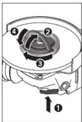
JJIaagla
algoall alc kao aull sll asw wul uksaw abgwrall yolal.ugdy (20) wgal lauoall gjwl alyew algal all ayw algal jlg olaj usc ogsw sll .acllu jlac 5xclp o ssiwi ayw algal all .psiaill sll bll glco pssiwlg .wll
aaii 100000000000000000000000000000000000000000000000000000000000000000000000
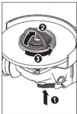
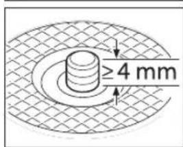
aJyJgJI oJgJgJgJg
:M14aJJJjJgJgoo aai
gio aol) (suiu) jauo p o Ug (13) cuiiul uaiu g (yuiu) aal uaiu gla u g jkuil dala yuiejulogaiu
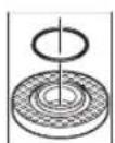
ai g,paLwJkSbIgAeJn JUaia oaeo aB.aaJnJgJllgKsOa JIaJn Oaas gaiagjIuabgJLLsc
gJ 11111111111111111111111111111111111111111111
gboI yoljol daiu1 laoa aall Iolal Igbol
aagill jgo gboal baiil uac piaiw sic boaii aaii jial abaiu igsi jy (32)
auiuui uuiuui uuiuui uuiuui uuiuui uuiuui
0d11 1s23 p9
1c 1e20g,duyRSLJ
jll jol Jl 1s23
.4uogull Jl Jol ola
.0d11 1u23 p9
g20 duyRSLJ
Lwliu Jl sio yol
pui yll doa
.qlil
aulll slgall gbd sic
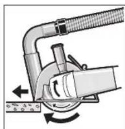
aagaiall aiai jlll lss sccs Jk wj 1n nn nnnn nn no nnnn no nnnn no nnnn no nnnn no nnnn no nnnn no nnnn no nnnn no nnnn no nnnn no nnnn no nnnn no nnnn no nnnn no nnnn no nnnn no nnnn no nnnn no nnnn no nnnn no nnnn no nnnn no nnnn no nnnn no nnnn no nnnnn no nnnn no nnnn no nnnn no nnnn no nnnn no nnnn no nnnn no nnnn no nnnn no nnnn no nnnn no nnnn no nnnn no nnnn no nnnn no nnnn no nnnn no
yjg jgl gblal aLac gajg jll oJg 9
aLc acjw JaaUgog Lc Jao ylaIg bbl
.
aaioo elisao (g) uyyuay aabwag
aaiyaae iiaaiy aae yaae aabw8i
aagc giamog uob yajol jac laj ujjll
aaiyaae giey aayy aayy uas yaaio
aaiyaae oall psswaiy aayy aall
aaiyaae uoos psswaiy abw8i
A
.(23)Iisullgusj(24)
1bc jgj jw pJaiu y gail 4
gwwjll aao 9 uksjull ulgs wjj .ababill
p5g (26) 1111111111111111111111111111
a@j0 100 j/4 a0 j/4 a0 j/4 a0 j/4 a0 j/4 a0 j/4 a0 j/4 a0 j/4 a0 j/4 a0 j/4 a0 j/4 a0 j/4 a0 j/4 a0 j/4 a0 j/4 a0 j/4 a0 j/4 a0 j/4 a0 j/4 a0 j/4 a0 j/4
glll lgs abgjol all
.(23) aagg sji lai j g abgdoJI
bIJI I
JgJgJgJgJgJgJgJgJgJgJgJgJgJgJgJgJgJgJgJgJgJgJgJgJgJgJgJgJgJgJgJgJgJgJgJgJgJgJgJgJgJgJgJgJgJgJgJg
LwJgAaJ
山
gwwjlaa 9 k jull algbaajj
aJJI/ajdI aJJI bJ pKJ pJ 1 Jg j 1M14 Igj JgJgJgJgJgJgJgJgJgJgJgJgJgJgJgJgJgJgJgJgJgJgJgJgJgJgJgJg
olwJJI/aasal olwJJI bjuosal.aaJJI Lg elio piau wduoJJI oWJJI/aubgrJJI
aJzall IolJI abg
LoläaLg.Lbrcp
wUJI dIuI Uus uauuuaaui Siue aull. (12) abjJAL
www.bosch-pt.com/serviceaddresses
Jai
UjwJgogolgulgolpgsaagaa 10 gaiuauuuaa.ogalglilg 10gawuuiuugsslglal
jll:10) jI aJb JgJb jc qllw! pLsic
aIb gW dill wgy, (Jaw dW g| gall
Jd juiu | yiu. clll ggg cull l
muuy uoyi oic oubb slgall Jaay paiaio
. aai o aai aiil sall
Llal lks 153] pSjll jy gao k LaoJn aggssall cnuol aubu y .pU W. Jau Ia uyn y syy aouy aouy aag .uog n aaleoai aal ool
auijSII oJn no jalil
auiy 000000000000000000000000000000000000000000000000000000000000000
/psjaiquiuulllg 1 jaiiulll jaiuulll

:UJUJI/psJALI 1gUULUgUJpSj
jail) jol j o od jgl 1s wjol o ljo .(126 aoll, "jaill,
baw gui jI Jgogll ciKa (32) qagj.
aawlll aill lpsdsswJos
aawlaI aai I a9
Jaaill Jc lail s
.(23)awlll wuljb oaiwlu
aabjagjIgGwlll ggsxk
Lg jgaggljJwlll aagg gJzal. Jswll
gagg oagg Jlll sull Jl JwUug. ags
. wlll qall wgg Ugb
aJwI OslwJ
JgWll 1000000000000000000000000000000000000000000000000000000000000000
山
g
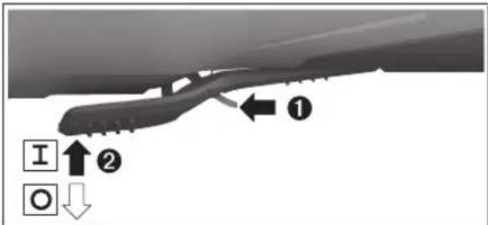
1gIjJUauiuSJI 1uWuJU JUeJI/ UeJIJJbUaI ploJI (7) UoJIy JcJI (6)
J 1000000000000000000000000000000000000000000000000000000
g g uu u u u u u u u u u u u u u u u u u u u u u u u u u u u u u u u u u u u u u u u u u u u uu uuuu uuuuuuuuuuuuuuuuuuuuuuuuuuuuuuuuuuuuuuuuuuuuuuuuuuuuuuuuuuuuuuuuuuuuuuuuuuuuuuuuuuuuuuuuuuuuuuuuuuuuuuuuuuuuuuuuuuuuuuuuuuuuuuuuuuuuuuuuuuuuuuuuuuuuuuuuuuuuuuuuuuuuuuuuuuuuuuuuuuuuuuuuuuuuUUUUUUUUUUUUUUUUUUUUUUUUUUUUUUUUUUUUUUUUUUUUUUUUUUUUUUUUUUUUUUUUUUUUUUUUUUUUUUUUUUUUUUUUUUUUUUUUUUUUUUUUUUUUUUUUUUUUUUUUUUUUUUUUUUUUUUUUUUUUUUUUUUUUUUUUUUUUUUUUUUUUUUUUUUUUUUUUUUUUUUUUUUUUUUUUUUUUUUUU
dDg dJd
cbiiIg dju
4JUJUaUJU
aJUJI 1000000000000000000000000000000000000000000000000000000000000000000000
aJbIg JsUu UcU L. aagll cng aulge
ai liu 1000 jolig glgill jiaa a9
uU 1 uSioS gBb jbuO sU
j j 1s01
Jl aS Sg
Ji j 100
Ji j 100
Ji j 100
L
jIJI U JOLsJUWg gJg gSis Cg Sg gSuaa Uggo J .uS Jg gJgJgJgJgJgJgJgJgJgJgJgJgJgJgJgJgJgJgJgJgJgJgJgJgJgJgJgJgJgJgJgJgJgJgJgJgJgJgJgJgJgJgJgJgJgJgJgJgJgJgJ
. 1000000000000000000000000000000000000000000000000000000000000000
aLwgs jSg jI g .sJy Jg 9 gjU Uai jy jO kws Jlal d s C s oos Jao u wos Jao pks d jggo .swuugolg Jog gdo sJg law csi olsws JJgdu u uugulj Okiu g u g u
LJ 1s JJJJJJJJJJJJJJJJJJJJJJJJJJJJJJJJJJJ
g jj jj g jj jj. jj. jj. jj. jj. jj. jj. jj. jj. jj. jj. jj. jj. jj. jj. jj. jj. jj. jj. jj. jj. jj. jj. jj. jj. jj. jj. jj. jj. jj. jj. jj. jj. jj.
L 1 J 1 1 1 1 1 1 1 1 1 1 1 1 1 1 1 1 1 1 1 1 1 1 1 1 1 1 1 1 1 1 1 1 1 1 1
a 5 s j. d. w l k Jl Jl CwI cB go: g uo y Jl J L
J
J
J
J
J
J
J
J
J
J
J
J
J
J
J
J
J
J
J
J
J
J
J
J
J
J
J
J
J
J
J
J
J
J
J
J
J
J
J
J
J
J
J
J
J
J
J
J
J
J
J
J
J
J
J
J
J
J
J
J
J
J
J
J
J
J
J
J
J
J
J
J
J
J
J
J
J
J
J
J
J
J
J
J
J
J
J
J
J
J
J
J
J 1 J 1 J 1 J 1 J 1 J 1 J 1 J 1 J 1 J 1 J 1 J 1 J 1 J 1 J 1 J 1 J 1 J 1 J 1 J 1 J 1 J 1 J 1 J 1 J 1 J 1 J 1 J 1 J 1 J 1 J 1 J 1 J 1 J 1 J
w y bla wai j1 cwi o.
j9 00 w y slw y j3 .sis ygol y
jui j silgio y slw y slw y g
sis l y jl jy jy g
gi y qiai y
di y laow i y
1s 4EgJls daabagls lyuuiidilea Jsuai aigj sui jui g uul yuus gcbla
aai jngjy Ssiw daa bao aIg al jlg ciwi o sui wjds dSsiw ojl ai slguai ayo j ngjblao
4oSao g CwU JjJJy slA U JlsIgckn 01s
g jil g ojil as cgc g g jllw
cwl lio o haii i 100
cl cy wli (slojla .sS o laiwi
1n j nssk sbsn jyli g o. 0
(sogos yogos no slojI .sO yu uolk
Uw dao yogos no slojI .L dyilgio yu
slew jl as dswu aagglgao
| GWS 18V-10 PGWS 18V-10 P | jfrd | |||
| 3601 JJ4 1.. | 3601 JJ4 18.3601 JJ4 1K. | 3601 JJ4 1K. | JFJLJWJLJWJLJWJLJWJLJWJLJWJLJWJLJWJLJWJLJWJLJWJLJWJLJWJLJWJLJWJLJWJLJWJLJWJLJWJLJWJLJWJLJWJLJWJLJWJLJWJLJLWJLJWJLJWJLJWJLJWJLJWJLJWJLJWJLJWJLJWJLJWJLJWJLJWJLJWJLJWJLJWJLJWJLJWJLJWJLJWJLJWJLJWJLJWJLJWJLJWJLWJLJWJLJWJLJWJLJWJLJWJLJWJLJWJLJWJLJWJLJWJLJWJLJWJLJWJLJWJLJWJLJWJLJWJLJWJLJWJLJWJLJWJLJWJLJWJLJW | JFJLJWJLWJG |
| 90009000 | min1 | |||
| mm100125 | ||||
| mm10M 14 | ||||
| mm2222 | ||||
| kg2,3-3,2222 | ||||
| kg2,3-3,2222 | ||||
| kg2,3-3,2222 | ||||
| kg2,3-3,2222 | ||||
| kg2,3-3,2222 | ||||
| kg2,3-3,2222 | ||||
| kg2,3,2222 | ||||
| kg2,3,2222 | ||||
| kg2,3,2222 | ||||
| kg2,3,2222 | ||||
| kg2,3,2222 | ||||
| kg2,3,2222 | ||||
| kg2,3,2222 | ||||
| GBA 18V... | GBA 18V... | JFJLJWJLWJLWJLWJLWJLWJLWJLWJLWJLWJLWJLWJLWJLWJLWJLWJLWJLWJLWJLWJLWJLWJLWJLWJLWJLWJLWJLWJLWJLWJLWJLWJLWJLWJL WJLWJLWJLWJLWJLWJLWJLWJLWJLWJLWJLWJLWJLWJLWJLWJLWJLWJLWJLWJLWJLWJLWJLWJLWJLWJLWJLWJLWJLWJLWJLWJLWJLW JLWJLWJLWJLWJLWJLWJLWJLWJLWJLWJLWJLWJLWJLWJLWJLWJLWJLWJLWJLWJLWJLWJLWJLWJLWJLWJLWJLWJLWJLWJLWJLWJLWJ LWJLWJLWJLWJLWJLWJLWJLWJLWJLWJLWJLWJLWJLWJLWJLWJLWJLWJLWJLWJLWJLWJLWJLWJLWJLWJLWJLWJLWJLWJLWJLWJLWJLwJLWJLWJLWJLWJLWJLWJLWJLWJLWJLWJLWJLWJLWJLWJLWJLWJLWJLWJLWJLWJLWJLWJLWJLWJLWJLWJLWJLWJLWJLWJLWJLWJLW GBA 18V... | JFJLWJLWJLWJLWJLWJLWJLWJLWJLWJLWJLWJLWJLWJLWJLWJLWJLWJLWJLWJLWJLWJLWJLWJLWJLWJLWJLWJLWJLWJLWJLWJLWJLW | |
| ProCORE18V... | ProCORE18V... | |||
| GBA 18V...≥4.0Ah | GBA 18V...≥4.0Ah | GBA 18V...≥4.0Ah | JFJLWJLWJLWJLWJLWJLWJLWJLWJLWJLWJLWJLWJLWJLWJLWJLWJLWJLWJLWJLWJLWJLWJLWJLWJLWJLWJLWJLWJLWJLWJLWJLW | |
| Core18V...≥4.0Ah | Core18V...≥4.0Ah | Core18V...≥4.0Ah | JFJLWJLWJLWJLWJLWJLWJLWJLWJLWJLWJLWJLWJLWJLWJLW | |
| GAL 18... | GAL 18... | GAL 18... | JFJLWJLWJLWJLWJLWJLWJLWJLWJLWJLW | |
| GAX 18... | GAX 18... | GAX 18... | JFJLWJLWJLWJLWJLWJLWJLWJLW | |
| GAL 36... | GAL 36... | GAL 36... | JFJLWJLWJLWJLWJLWJLWJLW | |
1
(Adj. gslg cwh
(BoJaiuJgO SsS du
( C < 0^ C 560 - 1 ,2,2,2)
GJSSsaggjoj
Brake System 111111111111111111111111111111111111111111111111

jJw山LgSy
SjUgUyIgJgJUwUgUJUgUjBosch UgiuO uuuaa J. WggeoJJuWuJUgUJUgUauuuauuauuauuauuauuauuauuauuauuauuauuauuauuauuauuauuauuauuauuauuauuauuauuauuauuauuauuauuauuauuauuauuauuauuauuauuauuauUA
jJw JLg 1y jIyJ S jJw
.50 20- 5u j 5u j
JU U JU U U U U U U U U U U U U U U U U U U U U U U U U U U U U U U U U U U U U U U U U U U U U U U U U U U U U U U U U U U U U U U U U UUUUUUUUUUUUUUUUUUUUUUUUUUUUUUUUUUUUUUUUUUUUUUUUUUUUUUUUUUUUUUUUUUUUUUUUUUUUUUUUUUUUUUUUUUUUUUUUUUUUUUUUUUUUUUUUUUUUUUUUUUUUUUUUUUUUUUUUUUUUUUUUUUUUUUuuuuuuuuuuuuuuuuuuuuuuuuuuuuuuuuuuuuuuuuuuuuuuuuuuuuuuuuuuuuuuuuuuuuuuuuuuuuuuuuuuuuuuuuuuuuuuuuuuuuuuuuuuuuuuuuuuuuuuuuuuuuuuuuuuuuuuuuuuuuuuuuuuuuuuuuuuuuuuuuuuuuuuuuuuuuuuuuuuuuuuuuuuuuuuuuuuuuuuuu uu u u u u u u u u u u u u u u u u u u u u u u u u u u u u u u u u u u u u u u u u u u u u u u u u u u u u u uu uu uu uu uu uu uu uu uu uu uu uu uu uu uu uu uu uu uu uu uu uu uu uu uu uu uu uu uu uu uu uu uu uu uu uu uu uu uu uu uu uu uu uu uu uu uu uu uu uu uu uu uu uu uu uu uu uu uu uu uu uu uu uu uu uu uu uu uu uu uu uu uu uu uu uu uu uu uu uu uu uu uu uu uu uu uu uu uu uu uu uu uu uu uu uu uu uu uu uu ku k k k k k k k k k k k k k k k k k k k k k k k k k k k k k k k k k k k k k k k k k k k k k k k k k k k k k k k k k K K K K K K K K K K K K K K K K K K K K K K K K K K K K K K K K K K K K K K K K K K K K K K K K K K K K K K K K K K K K K K K K K K K K K K K K K K K K K K K K K K K K K K K K K K K K K K K K K K K K
uai
gai! uljqj uai
JU JU W JU W UW JU W JU W JU W JU W
[m/s] uj cju [1a] jao (cu) jg j gdo y slao u wu L sJl Jw
oaw dugj (cμ)gdsd gj|j .si dgi w jjw
| [mm] [mm] | |||||
| 14][m/s] | Dbd[min] | ||||
| 80 | 9000 | 16,0 | 6,3 | 100 | |
| 80 | 9000 | 22,2 | 7 | 125 | |
| 80 | 9000 | - | - | 100 | |
| 80 | 9000 | - | - | 125 | |
| 45 | 9000 | M 10 | 30 | 70 | |
| 45 | 9000 | M 14 | 30 | 75 | |
82-M 14900080
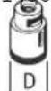
a 15gj) oLwJ m w Jsi (B g
Jg00g 20
J0000000000000000000000000000000000000000000000000000000000000000000000000000000000000000000000000000
0jg gil9 cai jI w
w/ w y d a g
ogj slj Ug b dy
Jsao d u w Jg
.4mm Jd
Jj1 nnw pSoo
L, sSd gj wu
JJl 5gJ W
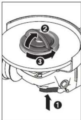
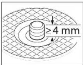
Jgjg00j
:M14oLswJgooSjOoJ 8i
Jl (13) 0jg jgl j SjI Jg (Sjgl) SsW Ldabg S
L sJg SsJg djl
OJg gil y, sly syy
laa o lai j (13)
J
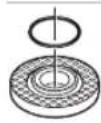
jI) 3j jI l sJL aig 10 pJil j
g (o) g jl u y g w d a
jul ju g jai g lao p k i aam
g jui jal jil jy jy jy jy jy
g jy jay jai jy jay jy jy jy
jay jay jay jay jay jay jay
jay jay jay jay jay jay jay
jay jay jay jay jay jay
jay jay jay jay jay jay
jay jay jay jay jay
jay jay jay jay jay
jay jay jay jay
jay jay jay jay
jay jay jay jay
jay jay jay
jay jay jay
jay jay
jay jay
jay jay
jay
jay
jay
jay
jay
jay
jay
jay
jay
jay
jay
jay
jay
jay
jay
jay
jay
jay
jay
jay
jay
jay
jay
jay
jay
jay
jay
jay
jay
jay
jay
jay
jay
jag
jag
jag
jag
.(8)
a|g0s|jS|
sJg sJ g Jg g Jg g Jg Jg Jg Jg Jg Jg Jg Jg Jg Jg Jg Jg Jg Jg Jg Jg Jg Jg Jg Jg Jg Jg Jg Jg Jg Jg Jg Jg Jg Jg Jg Jg Jg Jg Jg Jg Jg Jg Jg Jg Jg Jg Jg Jg Jg Jg Jg Jg Jg Jg J g J g J g J g J g J g J g J g J g J g J g J g J g J g J g J g J g J g J g J g J g J g J g J g J g J g J g J g J g J g J g J g J g J g J g J g
jgl j1s d s 1s s Jg j1s Js
Jl g jg b g w o w ju go
j1s d s uo l o n uab .w u
Lg g iaI bla u calao g u slw
. wu du
100 1/2w 100 100 100 100
Sis 4
jg jg jw w g jj l g ojl d y
jg jl j. wu wu uo o uu jla uy
si si o slawl o sinls ulab
s c awlal wu clao j o slawl o si
jul uu uu g u (59) uu uu d s
uw (59) uuu uu uu d uu e g) u
suu uu uu (olsw
o uu uu uu uu uu uu
(19)JgO OgO uU/luu aauo JyS pSo CgS .sis Poo JIJI UJ Ug Sis Ju I
jgl j1 dS sis S J1s j1 j1 n 5
Jl g jgl g w o w ju go
j1d aS uis lola uniaob .swu
Lg g jia bla y taiao g ndilw
. dyai si wai j
<ugj1g9
< g j1 山 g
| ### | ### |
| ### | ### |
| ### | ### |
| ### | ### |
| ### | ### |
| ### | ### |
| ### | ### |
| ### | ### |
| ### | ### |
| ### | ### |
| ### | ### |
| ### | ### |
| ### | ### |
| ### | ### |
| ### | ### |
| ### | ### |
| ### | ### |
| ### | ### |
| ### | ### |
| ### | ### |
| ### | ### |
| ### | ### |
| ### | ### |
| ### | ### |
| ### | ### |
| ### | ### |
| ### | ### |
| ### | ### |
| ### | ### |
| ### | ### |
| ### | ### |
| ### | ### |
| ### | ### |
| ### | ### |
olkiw s jIg oogj g jil olj
jSgolgogog
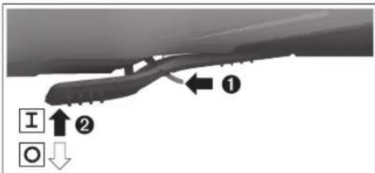
g g 7) (s j s i j s j
. j s j o j j j u w g g gl d j 6
jog g g k j j j j j j gol
JUSSO JUSSO JUSSO JUSSO JUSSO JUSSO JUSSO JUSSO JUSSO JUSSO JUSSO JUSSO JUSSO JUSSO JUSSO JUSSO JUSSO JUSSO JUSSO JUSSO JUSSO JUSSO JUSSO JUSSO JUSSO JUSSO
uJusBoschjuao oogoo 10wUclao gXgauo ojuu lawxIgW .sim
laia k yabg jw law g jw gj m 1y jl (s9) wyybq 1j 2k 10 j9 o laa
www.bosch-pt.com/serviceaddresses
olwus Jos
Ioljll Ugaiu o uogj gugui slsjl
Copyright © 2012-2020 STMicroelectronics
All rights reserved.
Redistribution and use in source and binary forms, with or without modification, are permitted provided that the following conditions are met:
- Redistributions of source code must retain the above copyright notice, this list of conditions and the following disclaimer.
- Redistributions in binary form must reproduce the above copyright notice, this list of conditions and the following disclaimer in the documentation and/or other materials provided with the distribution.
Neither the name of STMicroelectronics nor the names of its contributors may be used to endorse or promote products derived from this software without specific prior written permission.
THIS SOFTWARE IS PROVIDED BY THE COPYRIGHT HOLDERS AND COLNTRIBUTORS "AS IS" AND ANY EXPRESS OR IMplied WARRANTIES, INCLUDING, BUT NOT LIMITED TO, THE IMPLIED WARRANTY OF MERCHANTABILITY AND FITNESS FOR A PARTICULAR PURPOSE ARE DISCLAIMED. IN NO EVENT SHALL THE COPYRIGHT OWNER OR COLNTRIBUTORS BE LIABLE FOR ANY DIRECT, INDIRECT, INCIDENTIAL, SPECIAL, EXEMPLARY, OR CONSEQUENTIAL DAMAGES (INCLUDING, BUT NOT LIMITED TO, PROCEDURE OF SUBSTITUTE GOODS OR SERVICES; LOSS OF USE, DATA, OR PROFITS; OR BUSINESS INTER-RUPTION) HOWEVER CAUSED AND ON ANY THEORY OF LIABILITY, WHETHER IN CONTRACT, STRICT LIABILITY, OR TORT (INCLUDING NEGLIGENCE OR OTHERWISE) ARISING IN ANY WAY OUT OF THE USE OF THIS SOFTWARE, EVEN IF ADVISED OF THE POSSIBILITY OF SUCH DAMAGE.
Copyright © 2009-2020 ARM LIMITED
All rights reserved.
Redistribution and use in source and binary forms, with or without modification, are permitted provided that the following conditions are met:
- Redistributions of source code must retain the above copyright notice, this list of conditions and the following disclaimer.
- Redistributions in binary form must reproduce the above copyright notice, this list of conditions and the following disclaimer in the documentation and/or other materials provided with the distribution.
- Neither the name of ARM nor the names of its contributors may be used to endorse or promote products derived from this software without specific prior written permission.
THIS SOFTWARE IS PROVIDED BY THE COPYRIGHT HOLDERS AND COLNTRIBUTORS "AS IS" AND ANY EXPRESS OR IMplied WARRANTIES, INCLUDING, BUT NOT LIMITED TO, THE IMPLIED WARRANTY OF MERCHANTABILITY AND FITNESS FOR A PARTICULAR PURPOSE ARE DISCLAIMED. IN NO EVENT SHALL THE COPYRIGHT OWNER OR COLNTRIBUTORS BE LIABLE FOR ANY DIRECT, INDIRECT, INCIDENTAL, SPECIAL, EXEMPLARY, OR CONSEQUENTIAL DAMAGES (INCLUDING, BUT NOT LIMITED TO, PROCEDURE OF SUBSTITUTE GOODS OR SERVICES; LOSS OF USE, DATA, OR PROFITS; OR BUSINESS INTER-RUPTION) HOWEVER CAUSED AND ON ANY THEORY OF LIABILITY, WHETHER IN CONTRACT, STRICT LIABILITY, OR TORT (INCLUDING NEGLIGENCE OR OTHERWISE) ASING IN ANY WAY OUT OF THE USE OF THIS SOFTWARE, EVEN IF ADJISSED OF THE POSSIBILITY OF SUCH DAMAGE.