
Control Station - Swimming Pool HAYWARD - Free user manual and instructions
Find the device manual for free Control Station HAYWARD in PDF.
| Brand | Hayward |
| Model | Control Station |
| Category | Pool |
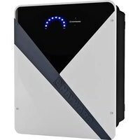
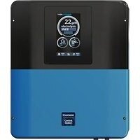
| Product Type | Pool control and regulation system |
| Dimensions (L x H x D) | 270 x 220 x 150 mm |
| Power supply | 230 V ~ 50 Hz |
| Current consumption | 100 mA |
| Power consumption | 23 W |
| Protection rating | IPX4 |
| Main functions | Filtration control, peripheral equipment (heat pump, lighting), liquid chlorine injection, pH/ORP regulation, temperature probe, flow detector, 3 auxiliary relays, WiFi option and remote display |
| Compatible pump type | Single-speed or variable speed (Hayward with digital inputs) |
| Number of peristaltic pumps | 2 (1 acid, 1 chlorine) |
| Output relays | pH, Chlorine, Aux2 (voltage 230V, 1A max); Filter Pump, Light, Aux3, Aux4 (dry contact) |
| Fuses | 1 x 3.15 A (pumps), 1 x 630 mA (electronics) |
| Electrical safety | Residual current device (RCD) 30 mA max, minimum horizontal distance 3.5 m from pool |
| Installation conditions | Dry, temperate, ventilated technical room, protected from acid vapors |
| Probes supplied | pH probe, ORP probe, temperature probe |
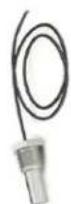
| Flow detector | Installed on return pipe, requires 25 cm straight section upstream |
| Heater connection | Via Aux4, compatible with Hayward systems (Energyline, EasyTemp, EcoPac, PowerLine) and other brands with remote On/Off control |
| WiFi option | WiFi module for monitoring via poolwatch.hayward.fr |
| Remote display option | Remote kit for wall mounting (not supplied) |
| Recommended calibration | pH probe: every month; ORP probe: every 2 months; temperature probe: as needed |
| Probe maintenance | Clean with soft toothbrush + toothpaste or liquid detergent; replace if unstable after cleaning |
| Winterization | Drain water from pipes, store probes in caps filled with water or KCl solution, in a frost-free location |
| Warranty | 2 years against manufacturing defects (consumable parts excluded) |
| Box contents | Control box, switch, power cable, fuses, pH/ORP/temperature probes, peristaltic pumps, flow detector, clamping collars, injection valves, PVC and PE tubes |
Frequently Asked Questions - Control Station HAYWARD
User questions about Control Station HAYWARD
0 question about this device. Answer the ones you know or ask your own.
Ask a new question about this device
Download the instructions for your Swimming Pool in PDF format for free! Find your manual Control Station - HAYWARD and take your electronic device back in hand. On this page are published all the documents necessary for the use of your device. Control Station by HAYWARD.
USER MANUAL Control Station HAYWARD
natural_image
Abstract geometric logo with stylized letter H inside a circular frame (no text or symbols)HAYWARD®
natural_image
Exterior view of a black industrial air conditioning unit with digital display and control buttons (no readable text or symbols)
GUIDE DE L'UTILISATEUR
OWNER'S MANUAL
MANUAL DEL USUARIO
MANUAL DO UTILIZADOR
ANWENDERHANDBUCH
GEBRUIKERSHANDLEIDING
MANUALE D'USO

natural_image
Abstract geometric logo with stylized letter H inside a circular frame (no text or symbols)HAYWARD®

natural_image
Exterior view of a black industrial air conditioning unit with digital display and control buttons (no readable text or symbols)
Control Station
GUIDE DE L'UTILISATEUR
CONSERVEZ CE MANUEL POUR UNE CONSULTATION ULTÉRIEURE


natural_image
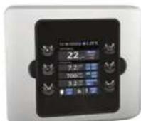
Front view of a black industrial electrical control panel with buttons and display (no readable text or symbols)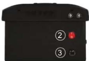
natural_image
Black electronic device with four labeled pins (4 and 5) and a connector, no visible text or symbols beyond labelsnatural_image
3D rendered mechanical device with transparent housing and four articulated limbs (no visible text or symbols)Chambre de mesure
natural_image
Four identical black metal bracket clips with screws, arranged in a 2x2 grid (no text or symbols)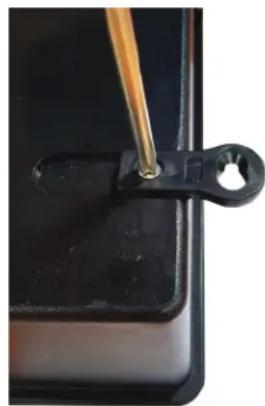
natural_image
Close-up of a black plastic clip holding a small circular hole, with a wooden tool inserted (no text or symbols visible)
natural_image
Black rectangular electronic device with four black metal clips attached (no visible text or symbols)N'UTILISEZ QUE DES PIÈCES DÉTACHÉES D'ORIGINE HAYWARD
bar
| Time | Phase | Temperature (°C) | |------|-------|------------------| | 0h | ON | 10 min | | 1h | OFF | 10 min | | 2h | ON | 28°C | | 3h | OFF | 28°C | | 4h | ON | 27°C | | 5h | OFF | 27°C | | 6h | ON | 28°C | | 7h | OFF | 28°C | | 8h | ON | 27°C | | 9h | OFF | 27°C | | 10h | ON | 28°C | | 11h | OFF | 28°C | | 12h | ON | 27°C | | 13h | OFF | 28°C | | 14h | ON | 27°C | | 15h | OFF | 28°C | | 16h | ON | 27°C | | 17h | OFF | 28°C | | 18h | ON | 27°C | | 19h | OFF | 28°C | | 20h | ON | 27°C | | 21h | OFF | 28°C | | 22h | ON | 27°C | | 23h | OFF | 28°C |natural_image
Abstract geometric logo with stylized letter H inside a circular frame (no text or symbols)HAYWARD®

natural_image
Exterior view of a black industrial air conditioning unit with digital display and control buttons (no readable text or symbols)
Control Station
OWNER'S MANUAL
PLEASE KEEP THIS MANUAL FOR FUTURE REFERENCE


WARNING: Electrical hazard. Failure to comply with these instructions can result in serious injuries or death. THE EQUIPMENT IS INTENDED TO BE USED ONLY IN SWIMMING POOLS
⚠ WARNING – Disconnect the equipment from the mains supply before any intervention.
⚠ WARNING – All electrical connections must be carried out by a qualified approved electrician in accordance with the standards currently in force in the country of installation.
| F NF | C 15-100 GB BS7671:1992 | |||
| D DIN VDE 0100-702 EW SIST HD 384-7-702.S2 | ||||
| A ÖVE 8001-4-702 H MSZ 2364-702:1994 / MSZ 10-533 1/1990 | ||||
| E UNE 20460-7-702 1993, REBT ITC-BT-31 2002 M MSA HD 384-7-702.S2 | ||||
| IRL | IS HD 384-7-702 | PL | TS IEC 60364-7-702 | |
| I | CEI 64-8/7 | CZ | CSN 33 2000 7-702 | |
| LUX | 384-7.702 S2 | SK | STN 33 2000-7-702 | |
| NL | NEN 1010-7-702 | SLO | SIST HD 384-7-702.S2 | |
| P RSIUEE | TR TS | IEC 60364-7-702 | ||
⚠ WARNING – Check that the device is plugged into a power outlet that is protected against short-circuits. The device must also be powered via an isolating transformer or a residual current device (RCD) with a nominal operating residual current not exceeding 30 mA.
⚠ WARNING– Ensure that children cannot play with the device. Keep your hands and any foreign object away from openings and moving parts.
⚠ WARNING – Check that the supply voltage required by the product corresponds to the voltage of the distribution network and that the power supply cables are suitable for the product power supply.
⚠ WARNING – Chemicals can cause internal and external burns. To avoid death, serious injury and/or damage to equipment, wear personal protective equipment (gloves, goggles, mask, etc.) when servicing or maintaining this device. This device must be installed in an adequately ventilated place.
⚠ WARNING – To reduce the risk of electric shock, do not use an extension cable to connect the device to the mains. Use a wall socket.
⚠ WARNING – Carefully read the instructions that appear in this manual and on the device. Failure to comply with the instructions can cause injuries. This document must be given to every pool user, who should keep it in a safe place.
⚠ WARNING – The appliance can be used by children aged from 8 years and above and persons with reduced physical, sensory or mental capabilities, or lack of experience and knowledge, if they have been given supervision or instruction concerning use of the appliance in a safe way and understand the hazards involved.
⚠ WARNING – Use only original Hayward parts.
⚠ WARNING – If the power supply cable is damaged, it must be replaced by the manufacturer, the after-sales service or similarly qualified persons to avoid danger.
⚠ WARNING – The device must not be used if the power cord is damaged. An electric shock could occur. A damaged power cord must be replaced by the after-sales service or similarly qualified persons to avoid danger.
USE ONLY GENUINE REPLACEMENT PARTS
REGISTRATION
Thank you for choosing Hayward. This manual contains important information regarding the operation and maintenance of your product. Please retain it for reference.
TO REGISTER YOUR PRODUCT IN OUR DATABASE, GO TO:
www.hayward.fr/en/services/register-your-product

For Your Records
Record the following information for your convenience:
1) Purchase Date
2) Complete Name ____
3) Address
4) Zip code
5) Email Address
6) Part number Serial number
7) Pool Dealer
8) Address
9) Zip code ____ Country ____
Note

GENERAL
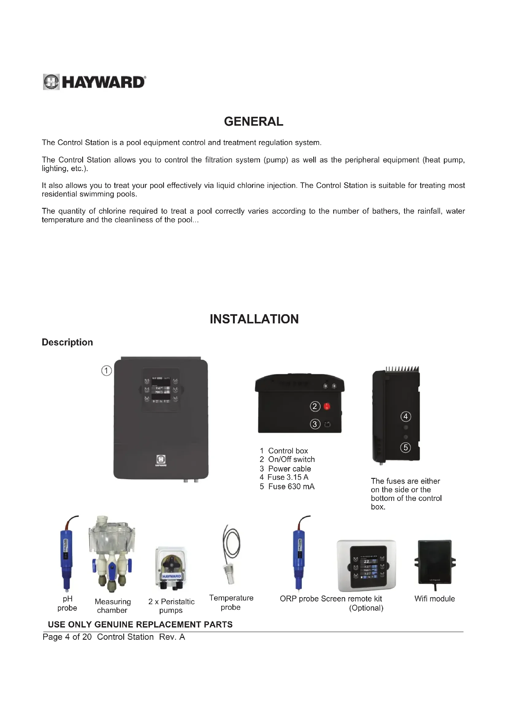
The Control Station is a pool equipment control and treatment regulation system.
The Control Station allows you to control the filtration system (pump) as well as the peripheral equipment (heat pump, lighting, etc.).
It also allows you to treat your pool effectively via liquid chlorine injection. The Control Station is suitable for treating most residential swimming pools.
The quantity of chlorine required to treat a pool correctly varies according to the number of bathers, the rainfall, water temperature and the cleanliness of the pool...
INSTALLATION
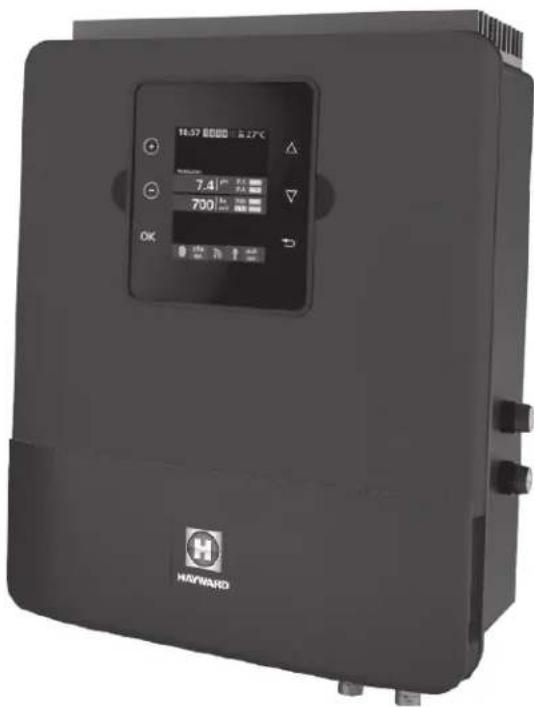
Description
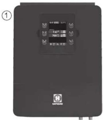
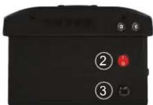
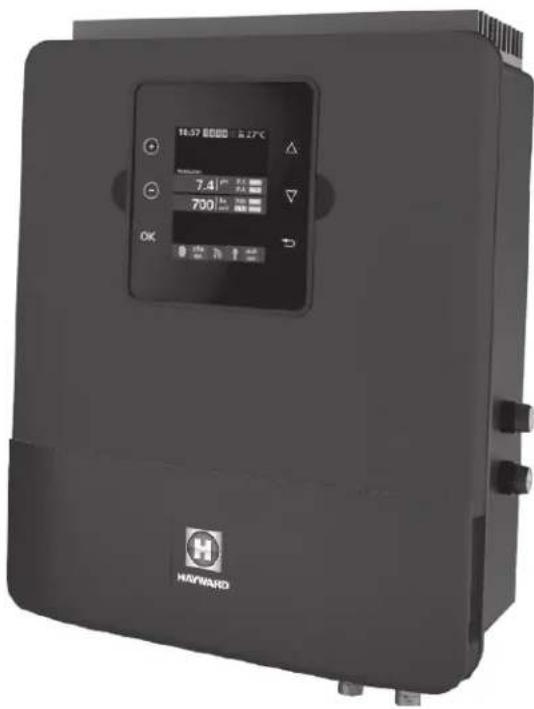
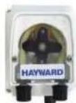
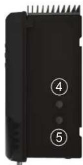
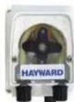
1 Control box
2 On/Off switch
3 Power cable
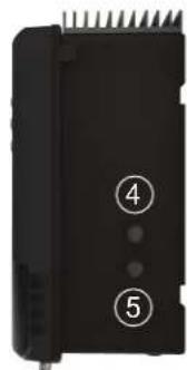
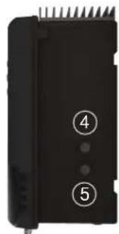
4 Fuse 3.15 A
5 Fuse 630 mA
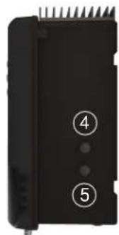
natural_image
Black electronic device with labeled pins (4 and 5) and a connector, no readable text or symbols beyond labelsThe fuses are either on the side or the bottom of the control box.
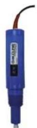
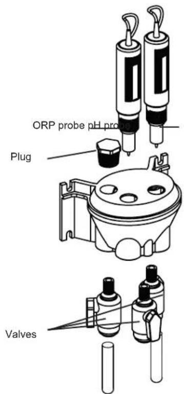
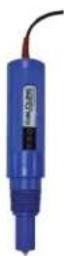
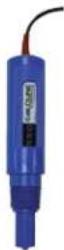
pH probe
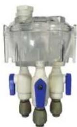
natural_image
Close-up of a transparent medical device with four white and beige ports, no visible text or symbolsMeasuring chamber
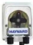
2 x Peristaltic pumps
Temperature probe
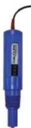
ORP probe Screen remote kit (Optional)
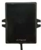
Wifi module
USE ONLY GENUINE REPLACEMENT PARTS
Wall-mounted installation
Fix the box and the measuring chamber on the wall (optional). The box must be installed in the equipment room (dry, temperate, ventilated). Caution, acid vapours can cause irreversible damage to your device. Position the treatment product tanks accordingly.
The Control Station must be fitted a minimum horizontal distance of 3.5 m (or more, if required by local regulations) from the pool.
The box must be placed vertically on a flat surface, with the cables downwards. As this box is also used to evacuate heat (heat dissipation from internal components), it is important that the four sides of the box remain unobstructed. Do not to install the Control Station behind a panel or in an enclosed space.
Before installing the control unit in the intended location, check that the power cord can reach the protected outlet.

natural_image
Four black metal bracket clips with screws attached, arranged in a 2x2 grid (no text or symbols)
natural_image
Close-up of a black plastic clip holding a small hole, with a wooden tool inserted (no text or symbols visible)
natural_image
Black rectangular electronic component with four metallic clips and mounting holes (no visible text or symbols)Disconnect the pool filtration pump before starting the installation. The system must be installed in accordance with the standards currently in force in the country of installation. The control box must be fitted a minimum horizontal distance of 3.5 m (or more, if required by local regulations) from the pool, within 1 m of a protected outlet. Install and use the product at an altitude below 2000 m.
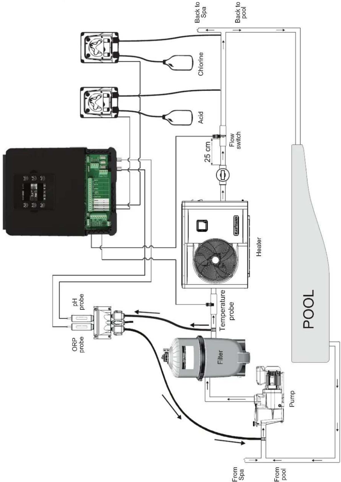
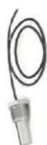
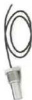
The flow switch must be installed on the return pipe directly in line with and upstream of the treatment product injection point. Allow a 25 cm straight section before the flow switch. A hole should previously have been drilled in the pipe to allow the flow switch to pass through. Screw the flow switch into the saddle clamp, taking care to seal with Teflon. Then install the clamp on the pipe. The flow switch must be installed in the direction of operation to ensure that it is tripped by the flow from the filtration pump.
The device used to inject the treatment products (acid, etc.) must be installed last on the water return line, after any equipment (heater, etc.). A hole should previously have been drilled in the pipe to allow the treatment product to pass through. Install the saddle clamp and screw the injection valve into the saddle clamp using the adapter provided. Seal with Teflon.
Use the transparent PVC hose for suction (between the tank and the peristaltic pump) and the semi-rigid white polyethylene tube for injection (between the peristaltic pump and the injection valve).
All the metal components of the swimming pool can be connected to the same earth as per local regulations
flowchart
graph TD
    A["Pump"] --> B["Filter"]
    B --> C["ORP probe"]
    B --> D["pH probe"]
    C --> E["Temperature probe"]
    D --> E
    E --> F["Heater"]
    F --> G["Flow switch"]
    G --> H["Acid"]
    G --> I["Chlorine"]
    H --> J["Back to Spa"]
    I --> K["Back to pool"]
    L["From pool"] --> M["Pump"]
    N["From Spa"] --> O["Pump"]
    P["POOL"] --> Q["Flow switch"]
    Q --> R["Heater"]
    R --> S["Heat Exchanger"]
    style A fill:#f9f,stroke:#333
    style P fill:#f9f,stroke:#333
    style N fill:#f9f,stroke:#333
    style L fill:#ccf,stroke:#333
    style P fill:#ccf,stroke:#333
    style Q fill:#cfc,stroke:#333
USE ONLY GENUINE REPLACEMENT PARTS
Connecting the water supply points
Install the measuring chamber as close as possible to the pool pipes to avoid head losses.
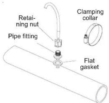
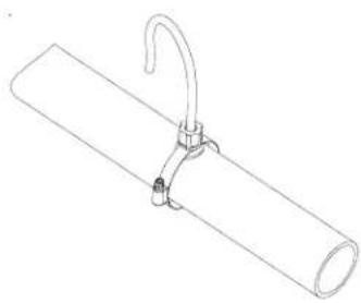
Drill a 10 mm hole. Place the flat gasket on the pipe fitting and insert the assembly into the hole, as illustrated below. Tighten the fitting with the clamp provided. Once the fitting has been secured to the pool pipe, insert the hose firmly into the pipe and tighten the retaining nut by hand.
natural_image
Line drawing of a cylindrical pipe with a hook attached to its side (no text or symbols)Installing the pH and ORP probes on the measuring chamber
The pH and ORP probes are "wet" packed and protected by plastic caps. The probes must always remain wet. If the probes are allowed to dry, they will be permanently unusable (not covered by the warranty) and the pH-ORP test kit will be ineffective.
Remove the pH and ORP probes from their plastic protective caps and set the caps aside for later use (wintering). To ensure that the probes remain wet at all times, fill the measuring chamber with pool water before installing the probes. Apply a length of Teflon tape to the probe threads. Tighten the probes by hand only. Check that they are watertight at startup. If the probes leak, do not tighten them further, but remove the Teflon tape and apply a new one.
After installation, check that the probes are constantly in contact with the water in the pool. When the filtration pump is not running (even for long periods), the water remaining in the chamber may be sufficient to protect the probes.
USE ONLY GENUINE REPLACEMENT PARTS
Electrical installation and wiring
Connect the Control Station to a permanent power outlet.
This circuit must be protected by a residual current device (RCD) (residual current: 30 mA max.).
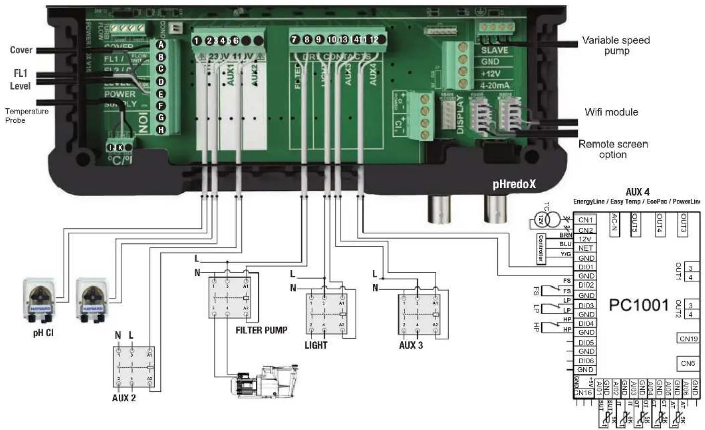
Description of outgoing relays
| Name | Description | Terminals | Type of output | Imax |
| pH | Peristaltic acid pump 230 V ^v | 1 - 2 | Voltage output | 1 A |
| Cl | Peristaltic chlorine pump 230 V ^v | 3 - 4 | Voltage output | 1 A |
| Aux2 | Auxiliary voltage output 230 V ^v | 5 - 6 | Voltage output | 1 A |
| Filter Pump | Filtration pump control | 7 - 8 | Dry contact | |
| Light | Lighting control | 9 - 10 | Dry contact | |
| Aux3 | Auxiliary dry contact | 11 - 12 | Dry contact | |
| Aux4 | Auxiliary dry contact (or heating control). | 13 - 14 | Dry contact |
If no heating system is installed on Aux4, it can be used as another auxiliary contact. To do this, contact Hayward technical support.
USE ONLY GENUINE REPLACEMENT PARTS
Connecting a heating system (Aux 4)
The Control Station is compatible with all types of pool heaters such as heat pumps, electric heaters or even heat exchangers.
Connecting to a Hayward heating system fitted with a remote On/Off control
Connect a 2 x 0.75 mm ^2 electric cable (not supplied) across terminals (13)-(14) of auxiliary contact Aux 4, then connect it across the DI01 and GND terminals on electronic circuit board PC1001/PC1002 of the Hayward heat pump or any other compatible equipment (see the installation instructions). Set the set point of the heat pump or heating system to maximum. The Control Station will use its own water temperature probe to control the heating set point.
Compatible equipment includes the seasonal Energyline Pro, the inverter Energyline Pro, the All Seasons Energyline Pro, EasyTemp, EcoPac, PowerLine and other brands with a remote On/Off control.
Connecting to a Hayward heating system not fitted with a remote On/Off control
In this case, the heating is controlled in series with the flow controller. Connect a 2 × 0.75 mm^2 cable in series with the flow control system.
Set the heating system set point to maximum. The Control Station will use its own water temperature probe to control the heating set point.
Connecting inputs:
| Name Description Terminals Type of input | |||
| FL1 Flow switch B - E Dry contact | |||
| Cover Not used A - E Dry contact | |||
| Level | Acid container level detection | D - E | Dry contact |
| ION | Not used | G - H | - |
| °C / F° | Black wire | K | - |
| Yellow wire | J | - | |
| Red wire | I | - | |
Characteristics
| Power supply | 230 V~ 50 Hz |
| Current consumption | 100 mA |
| Power consumption | 23 W |
| Safety rating | IPX4 |
| Characteristics of pH and ORP relays | Imax (pH+Cl+Aux2) = 3,15A , Pmax (PH+Cl+Aux2) = 725 W |
| Dimensions | 270 x 220 x 150 |
Connecting the ORP option (Optional)
Insert the ORP probe into the measuring chamber.
Connect the BNC connector on the ORP probe to the redox BNC input on the Control Station.
USE ONLY GENUINE REPLACEMENT PARTS
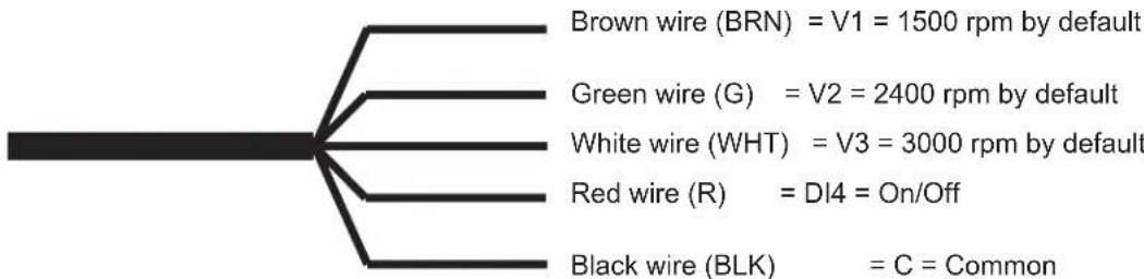
Connecting a Hayward variable-speed pump with digital inputs
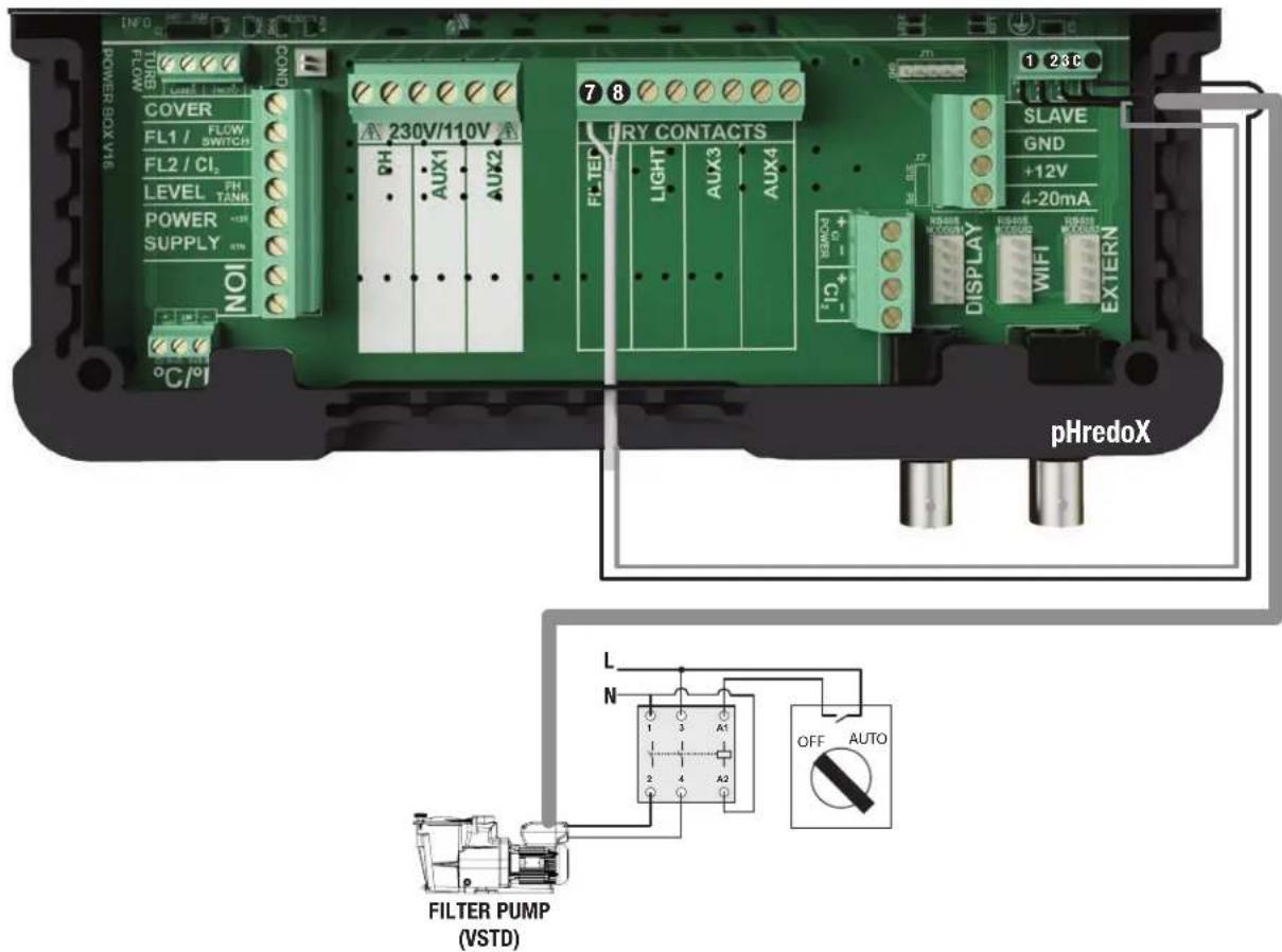
When using a Hayward variable-speed pump fitted with digital inputs, bridge the common black wire, connected to terminal (C), to terminal (7) and follow the connection instructions given in the following table. You will have to strip the digital cable back 15 cm and cut the orange wire.
flowchart
graph TD
    A["BRN"] --> B["= V1 = 1500 rpm by default"]
    C["Green"] --> D["= V2 = 2400 rpm by default"]
    E["White"] --> F["= V3 = 3000 rpm by default"]
    G["Red"] --> H["= DI4 = On/Off"]
    I["Black"] --> J["= C = Common"]
| Name | Description | Terminals | Colour |
| V1 | Low pump speed (V1) | 1 | Brown (BRN) |
| V2 | Average pump speed (V2) | 2 | Green (G) |
| V3 | High pump speed (V3) | 3 | White (WHT) |
| C | Common | C - 7 | Black (BLK) |
| DI4 | On/Off | 8 | Red (R) |
USE ONLY GENUINE REPLACEMENT PARTS
Assigning speeds
Whatever the filtration mode (Manual, Automatic, Smart, Heating or Intelligent), one of the three operating speeds (V1, V2 or V3) can be selected, thus providing a high degree of flexibility for setting and adjusting the water flow according to the equipment. The device will first have to be configured to take the variable-speed pump into account (see the section entitled "Setting the pump type").
The speed assigned to the "antifreeze" mode is V2.
Note: We should point out that the speed of all pool devices requiring a minimum water flow that is appropriate to their correct operation must be set manually before being stored in the memory and used by the Control Station (heat pump, chlorinator, etc.). See the variable-speed pump instructions for setting all the parameters related to its operation and safety.
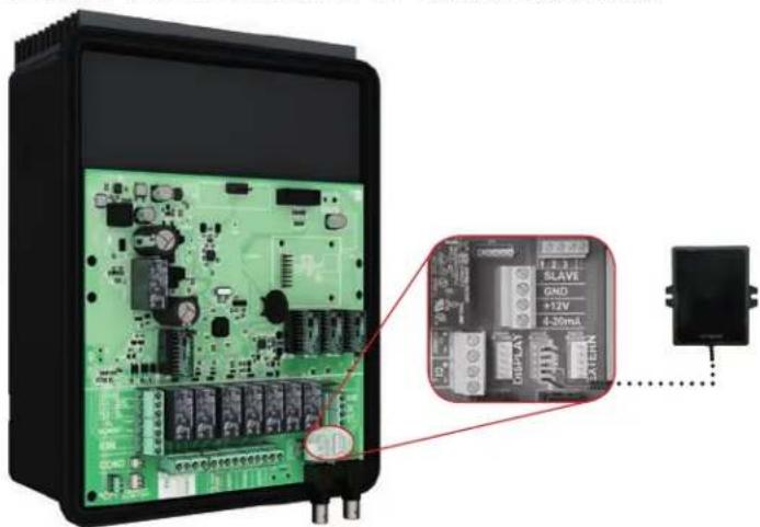
Connecting the Wifi option
The Wifi module must be installed in the equipment room (dry, temperate, ventilated) and located within reach of the wireless network cover to which it will be connected. Switch off the device before connecting the module. Plug the Wifi module connector into the RF / WIFI connector on the Control Station card.
natural_image
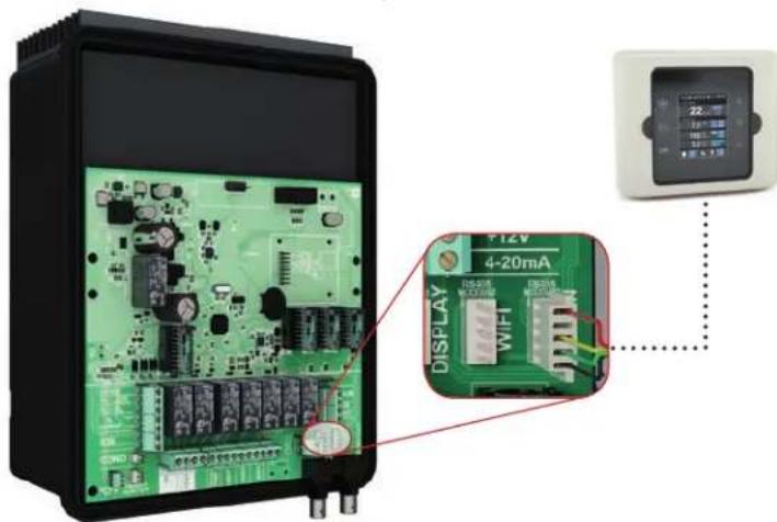
Electronic circuit board with green components and a close-up of an electronic module labeled 'SLAVE' connected to a power outlet (no readable text or symbols beyond labels)Installing the screen wall-mounting kit (not supplied)
Remove the screen from the box and unplug it.
Plug the extension connector into the DISPLAY connector on the Control Station card.
Plug the other end of the extension into the screen after first passing the cable through the wall bracket.
Fit the cover (supplied) over the front of the Control Station to replace the screen.
USE ONLY GENUINE REPLACEMENT PARTS
Chemical water balance
The water must be balanced manually BEFORE the device is started up.
The following table summarizes the concentrations recommended by Hayward. Your water should be checked regularly to maintain these concentrations and minimize surface corrosion or deterioration.
CHEMISTRY Recommended CONCENTRATIONS
| Free chlorine 1.0 to 3.0 | ppm |
| pH 7.2 to 7.6 | |
| Cyanuric acid (Stabilizer) | 20 to 30 ppm max.(Add stabilizer only if necessary)0 ppm in indoor pool |
| Total alkalinity 80 to 12 | 0 ppm |
| Water hardness 200 to | 300 ppm |
| Metals 0 ppm | |
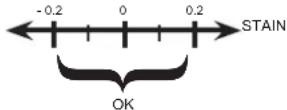
| Saturation index -0.2 to | 0.2 (preferably 0) |
Saturation index
The saturation index (Si) gives us information about the calcium content and alkalinity of the water; it is a water balance indicator. Your water is correctly balanced if the Si is 0 ± 0.2 . If the Si is below -0.2, the water is corrosive and the coating on the pool walls may be damaged. If the Si is above +0.2, stains may appear. Use the table below to determine the saturation index.
Use: Measure the pH of the pool water, the temperature, water hardness and total alkalinity. Use the table above to determine Ti, Cl and Al in the formula shown above. If the Si is equal to 0.2 or more, stains may appear. If the Si is equal to -0.2 or less, corrosion or deterioration may occur.
CORROSION
⚠ WARNING – Chemicals can cause internal and external burns. To avoid death, serious injury and/or damage to equipment, wear personal protective equipment (gloves, goggles, mask, etc.) when servicing or maintaining this device. The treatment products must be installed and/or stored in an adequately ventilated place.
USE ONLY GENUINE REPLACEMENT PARTS
OPERATION
The device is designed to be connected to a protected outlet at all times. The Control Station must not be disconnected unless the pool equipment is undergoing maintenance or the pool is to be closed (wintering).
Assuming that the chemical balance of the water is within the recommended ranges, the device can be started up.
Configuration
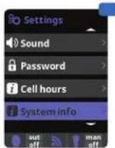
Settings
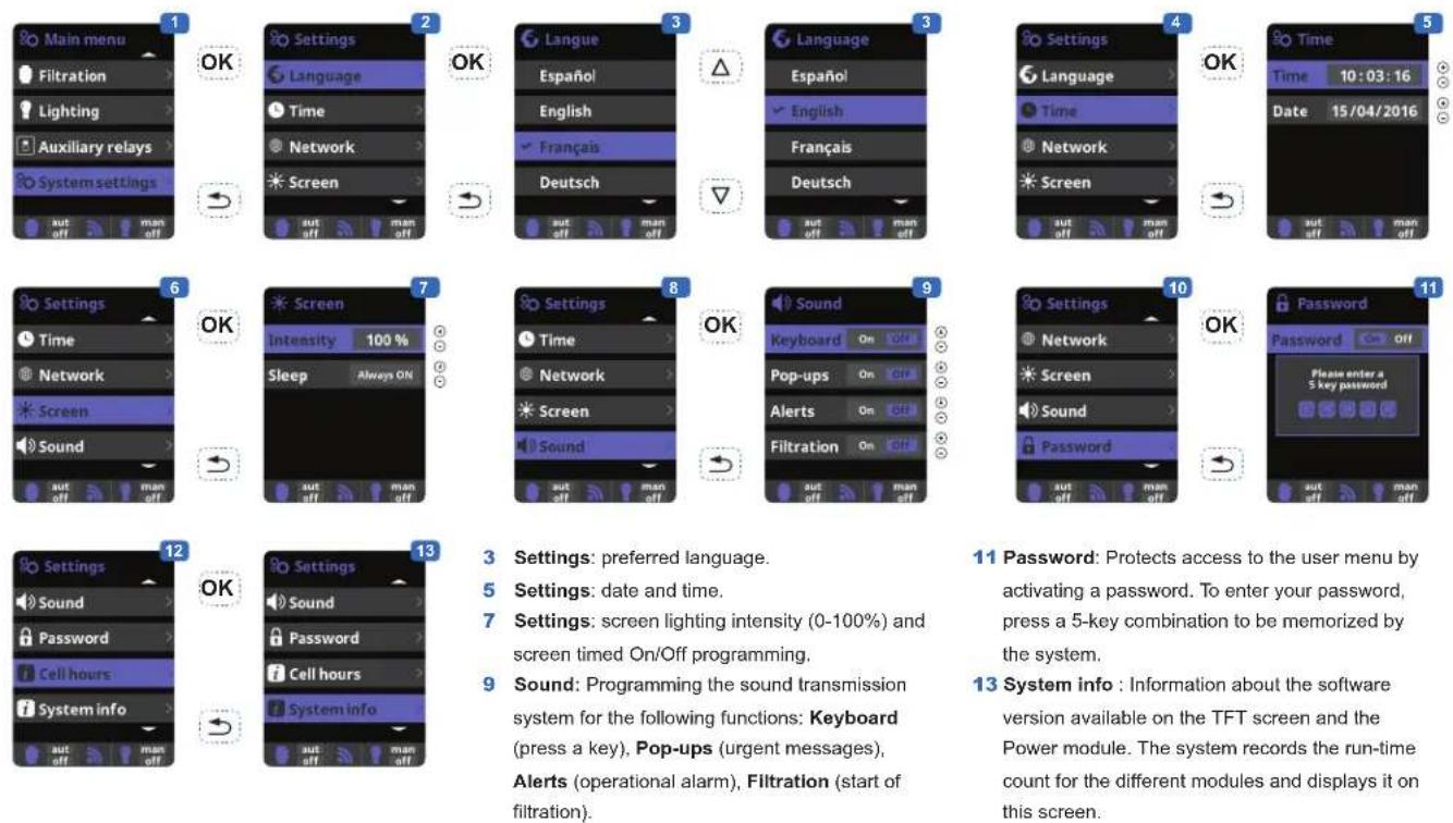
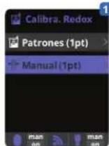
3 Settings: preferred language.
5 Settings: date and time.
7 Settings: screen lighting intensity (0-100%) and screen timed On/Off programming.
9 Sound: Programming the sound transmission system for the following functions: Keyboard (press a key), Pop-ups (urgent messages), Alerts (operational alarm), Filtration (start of filtration).
11 Password: Protects access to the user menu by activating a password. To enter your password, press a 5-key combination to be memorized by the system.
13 System info : Information about the software version available on the TFT screen and the Power module. The system records the run-time count for the different modules and displays it on this screen.
USE ONLY GENUINE REPLACEMENT PARTS
Setting the pH/ORP correction time
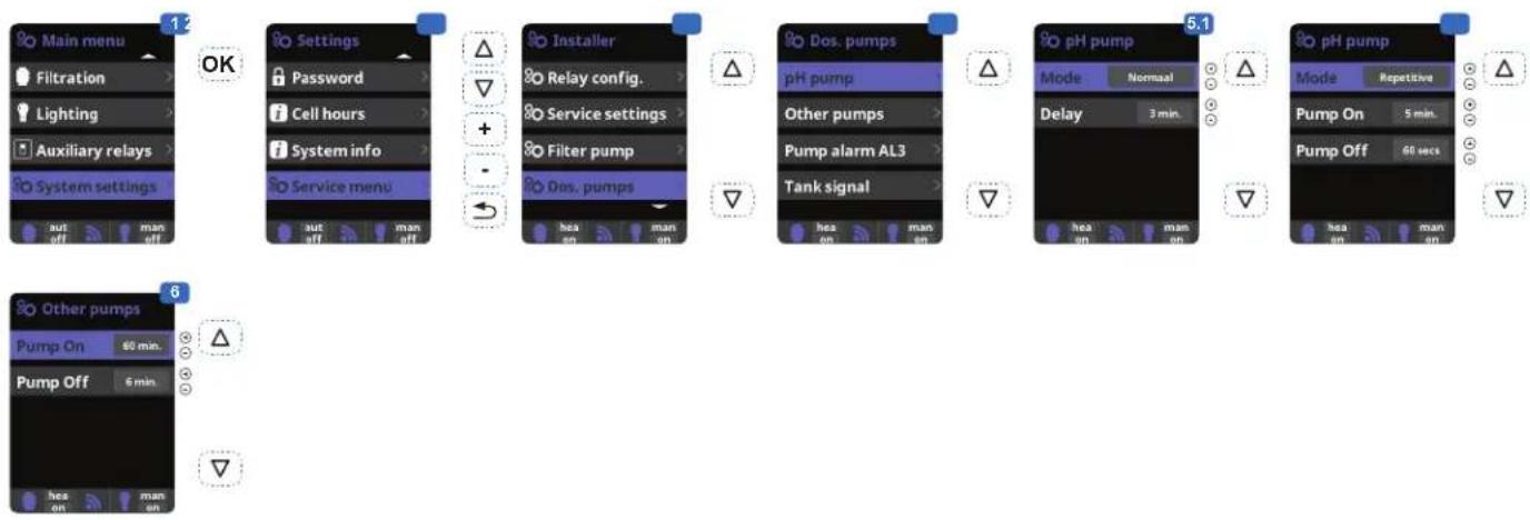
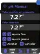
1 Setting the pH correction time.
The chemical parameters of the water must be set manually before the device is started up. If these adjustments are not made in advance, unwanted AL3 alarms may be tripped.
2 Enter the password: △ ▽ ⊙ ⊙
3 Select the "Dos. pumps" menu.
4 Select the "pH Pump" menu.
Do not change the default values on the "Pump alarm AL3" and "Tank signal" menus.
5.1 Allows you to set the pH pump to run continuously (Normal mode).
5.2 Allows you to set the pH pump to run intermittently (Repetition mode).
Caution: if the interval is too long, your pool may not be protected against acid overdoses and your equipment may be irreversibly damaged. Too short an interval may trip unwanted AL3 alarms.
6 Allows you to set the ON/OFF periods of the disinfectant pump.
Filtration
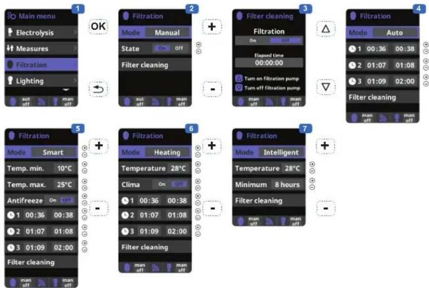
6 Heating: This mode acts in the same way as the automatic mode, but it can also operate via a relay that controls the temperature. The set point temperature is determined in this menu and the system operates with a hysteresis of one degree (for example: if the set point temperature is 23^ , the system will start up when the
temperature falls below 22^ C and shut down only when it rises above 23^ C).
Heating control OFF: The heating operates only during the filtration periods configured.
Heating control ON: Keeps the filtration on after
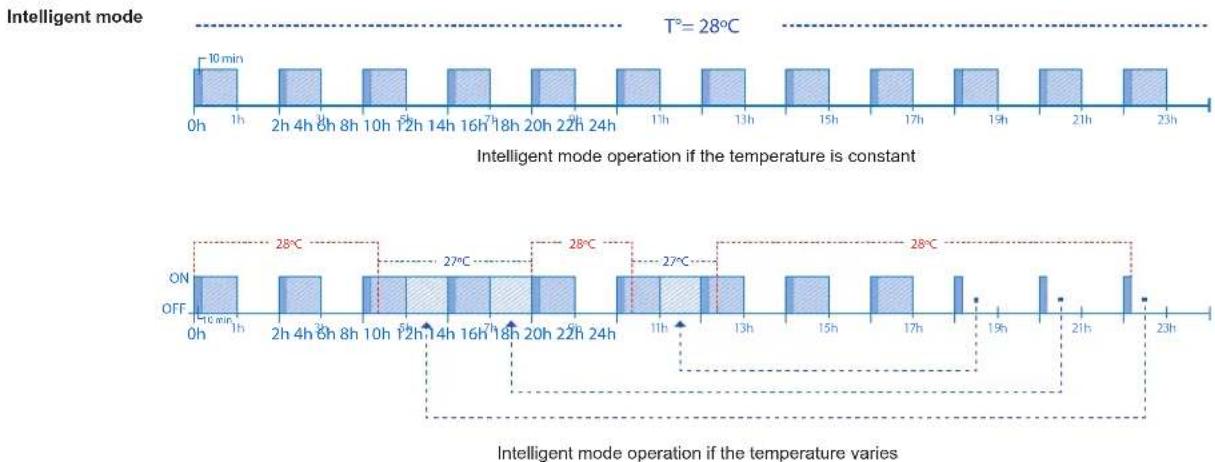
7 Intelligent*: In this mode, the user has two operating parameters: Select the required water temperature and the minimum filtration time (minimum two hours and maximum 24 hours). The filtration will operate for at least ten minutes every two hours to check the temperature. The minimum filtration time selected is divided into twelve sections that are added to its ten minutes. Example 1: Over twelve hours, the time
is divided between the twelve times a day when the filtration starts up to check the temperature. Example 2: (12 hours x 60 minutes) / 12 = 60 minutes every two hours. This is the filtration and heating period every two hours. If the programmed filtration period ends and the required temperature has not been reached, the filtration and heating remain on until the required temperature is reached. To minimize the
1 Filtration modes.
2 Manual: Allows the filtration process to be turned on and off manually.
3 Filter cleaning: This mode is used to backwash the filter.
4 Automatic: In this mode, filtration is turned on according to the start and end times set in the time slots. The time slots always operate on a daily basis.
5 Smart*: This mode is based on the automatic mode, with its three filtration intervals, but the filtration times are adjusted according to the temperature. This is done by setting two temperature parameters: the maximum temperature, above which the filtration times will be determined by the time slots, and the minimum temperature, below which filtration will be reduced to five minutes, the minimum operation period. Between these two temperatures, the filtration times will be staggered linearly. The antifreeze mode can be activated to turn the filtration on if the water temperature falls below 2°C.
the filtration period has expired if the temperature is below the set point temperature. When the setpoint temperature is reached, the filtration and heating stop and only resume when the next programming period begins.
number of hours during which filtration operates each day, this additional time will be deducted from the next filtration periods occurring during the rest of the day. (See the chart below).
bar
| Time | Operation | Temperature (°C) | |------|-----------|------------------| | 0h | ON | 18 min | | 1h | OFF | 28 | | 2h | ON | 27 | | 3h | OFF | 27 | | 4h | ON | 27 | | 5h | OFF | 27 | | 6h | ON | 27 | | 7h | OFF | 27 | | 8h | ON | 27 | | 9h | OFF | 27 | | 10h | ON | 27 | | 11h | OFF | 27 | | 12h | ON | 27 | | 13h | OFF | 27 | | 14h | ON | 27 | | 15h | OFF | 27 | | 16h | ON | 27 | | 17h | OFF | 27 | | 18h | ON | 27 | | 19h | OFF | 27 | | 20h | ON | 27 | | 21h | OFF | 27 | | 22h | ON | 27 | | 23h | OFF | 27 |USE ONLY GENUINE REPLACEMENT PARTS
Setting the pump type
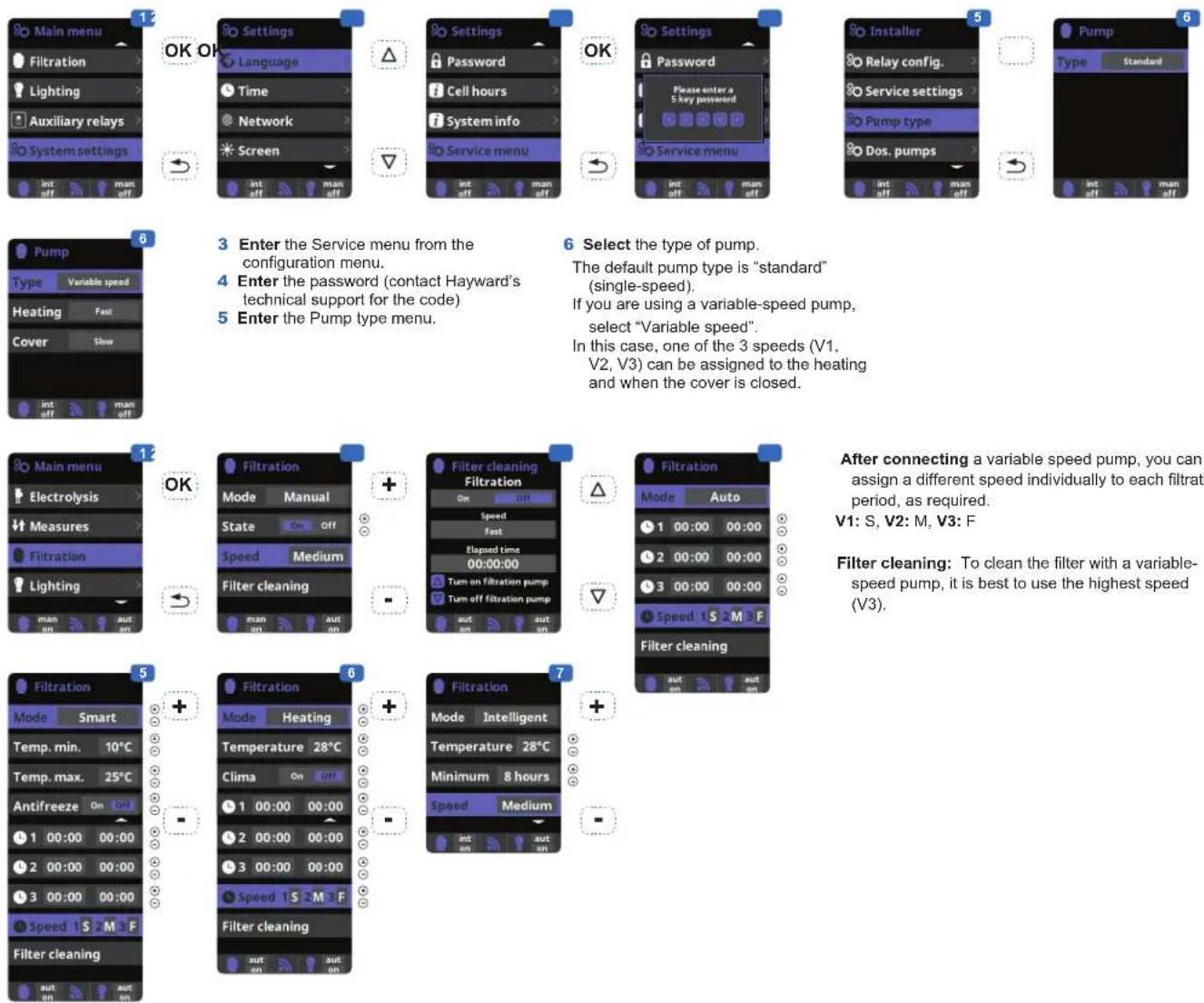
3 Enter the Service menu from the configuration menu.
4 Enter the password (contact Hayward's technical support for the code)
5 Enter the Pump type menu.
6 Select the type of pump.
The default pump type is "standard" (single-speed).
If you are using a variable-speed pump, select "Variable speed".
In this case, one of the 3 speeds (V1, V2, V3) can be assigned to the heating and when the cover is closed.
After connecting a variable speed pump, you can assign a different speed individually to each filtration period, as required.
V1: S, V2: M, V3: F
Filter cleaning: To clean the filter with a variable-speed pump, it is best to use the highest speed (V3).
Lighting
OK
OK
OK
© © © © ©
[Non-Text]
OK
-
[NO TEXT]
OK
-
[Non-Text]

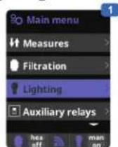
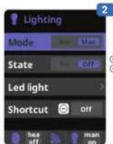
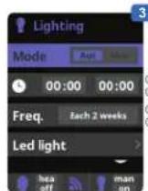
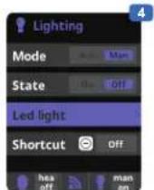
1 Lighting.
2 Manual mode (ON/OFF).
3 Automatic mode: Starts up according to the time slots used to set the lighting start and end times. The time slots can be configured with the following frequencies: daily, every 2 days, every 3 days, every 4 days, every 5 days, weekly, every 2 weeks, every 3 weeks, every 4 weeks.
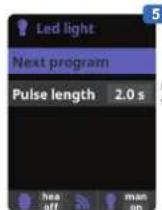
4 LED light: If you are using a coloured LED light, go to the menu to configure it.
5 Colour selection: This menu allows you to change the colours manually and, according to the type of LED light, program the pulse length required to cycle through the colours and programs (by default, 0.5 s, maximum 10 s).
6 Timed manual lighting (Shortcut): this menu allows you to set the maximum time the lights remain on before they switch off automatically after a predefined time.
The lighting can be switched on manually from the main screen by pressing the (-) button
USE ONLY GENUINE REPLACEMENT PARTS
Auxiliary relays
OK
→
+
[NO TEXT]
+
[Unreadable]
+
1
OK
[NO TEXT]
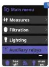
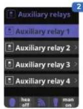
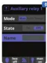
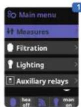
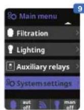
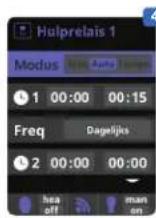
1 Auxiliary relays.
2 A maximum of 3 additional auxiliary relays (water features, fountains, garden lighting, etc.) can be controlled. This menu displays and allows you to configure the relays that remain available on your equipment.
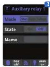
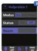
3 Manual mode (ON/OFF).
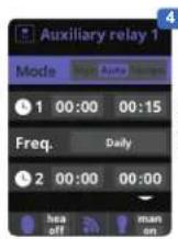
4 Automatic mode: Starts up according to the time slots used to set the start and end times. They can be configured with the following frequencies: daily, every 2 days, every 3 days, every 4 days, every 5 days, weekly, every 2 weeks, every 3 weeks, every 4 weeks.
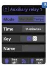
5 Timer mode: An operating time can be programmed in minutes. Each time you press the front panel key associated with the relay, it will be activated for the programmed time. This function is recommended for timing the operation of spa blowers.
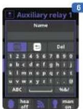
6 Relay name: It is possible to name the auxiliary relays individually according to the associated functions. On the keyboard, use the up/down arrows to move the cursor vertically and the +/- buttons to move the cursor horizontally. To confirm, press OK.
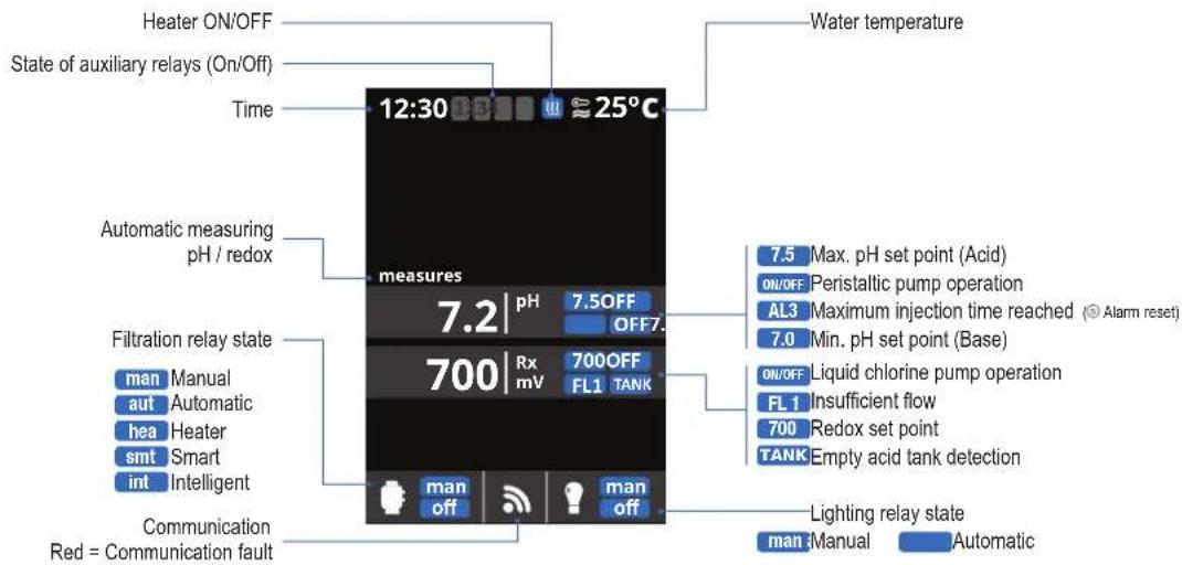
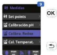
Measures
[Non-Text]
OK OK
(1)
[Non-Text]
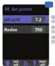
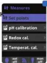
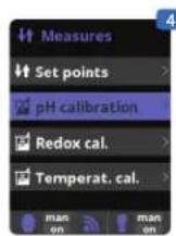
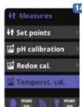
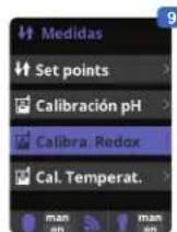
1 Measures: Adjustment of set points and measuring probes.
2 Set points for each measurement.
3 Setting the set points.
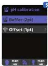
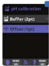
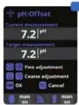
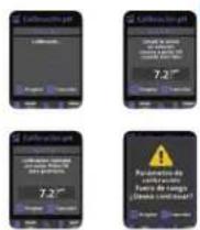
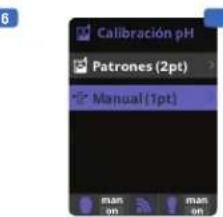
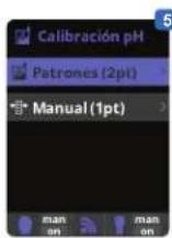
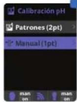
4 pH probe calibration: Recommended once a month during the pool season.
5 Calibration using buffer solutions (liquids models pH7 / pH10 / neutral). Follow the on-screen instructions (fig. 6).
7 Manual calibration: Allows you to set the probes to 1 point (without buffer solution) – recommended only for adjusting small deviations in readings.
OK
[NO TEXT]
OK
[NO TEXT]


6
OK
→

OK
→

[NO TEXT]
OK OK


11
12
(1)
→
8 Without removing the probe from the water, use the + / - keys to adjust the reading to your reference value (photometer or other measuring instrument).
9
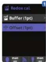
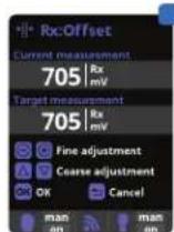
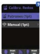
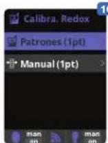
9 Redox probe calibration: Recommended every two months during the pool season.
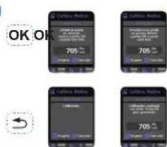
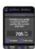
10 Calibration with reference solution 465 mV. Follow the on-screen instructions (fig. 11).
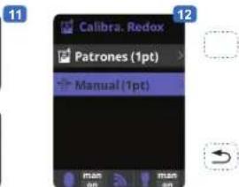
12 Manual calibration: Allows you to set the probes to 1 point (without solution)
– recommended only for adjusting small deviations in readings.
13 Without removing the probe from the water, use the + / - keys to adjust the reading to your reference value (photometer or other measuring instrument).
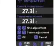
14 Temperature probe calibration: Allows you to set the probes to 1 point.
15 Without removing the probe from the water, use the + / - keys to adjust the reading to your reference value (thermometer). The same conditions should apply for measurements.
Setting the Wifi module
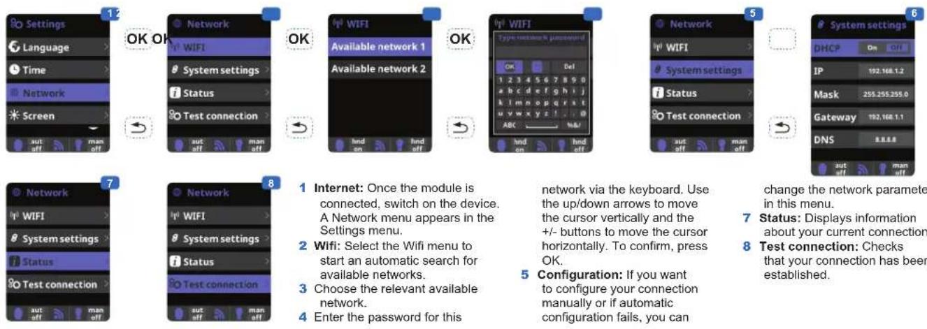
1 Internet: Once the module is connected, switch on the device. A Network menu appears in the Settings menu.
2 Wifi: Select the Wifi menu to start an automatic search for available networks.
3 Choose the relevant available network.
4 Enter the password for this
network via the keyboard. Use the up/down arrows to move the cursor vertically and the +/- buttons to move the cursor horizontally. To confirm, press OK.
5 Configuration: If you want to configure your connection manually or if automatic configuration fails, you can
change the network parameters in this menu.
7 Status: Displays information about your current connection.
8 Test connection: Checks that your connection has been established.
When the module is connected to the Wifi network and the two LEDs are on continuously (steady), you can register at poolwatch.hayward.fr.
Get your ID Node (see below) and follow the registration process.
Once you have registered, you can monitor all your Control Station parameters remotely.
OK
OK


Setting the redox level
The redox level tells you the oxidation potential, i.e. the disinfectant capacity of the water.
Setting the redox set point is the last step in setting the Control Station.
To find the optimum redox level for your pool, follow the steps below:
1) Start up the pool filtration system.
2) Add chlorine to the swimming pool until it reaches 1 to 1.5 ppm. This level is achieved with (approximately 1 to 1.5 g/m ^3 of water).
The pH level must vary between 7.2 and 7.5.
3) After 30 min. Check whether the level of free chlorine in the pool (manual DPD1 test kit) is between 0.8 and 1.0 ppm.
4) Look at the redox value on the screen and enter it as the redox set point.
5) The next day, check the free chlorine levels (manual DPD1 test kit) and the redox level. Increase / reduce the setting, if required.
Remember to check all your water parameters at regular intervals (2-3 months) (see table) and adjust the redox set point according to the steps listed above.
SERVICING
During the first 10-15 days, your system will require more attention:
- Check that the pH remains at the ideal level (7.2 to 7.4).
- If the pH is exceptionally unstable and uses a lot of acid, check the alkalinity (see table).
If the balance is highly unstable, contact your pool installer/builder.
REMEMBER that the system needs a certain amount of time to adapt to your pool and will require additional chemicals during the first 3-5 days.
The pool must be regularly maintained and the skimmer baskets emptied whenever necessary.
Also check that your filter is not clogged.
DOSING PUMPS: Check the levels regularly to ensure that the pumps do not run on empty. The dosing pumps must be checked and serviced at regular intervals.
Servicing the probes
The probes must be clean and free from oil, chemical deposits and contamination to function properly. As they are in continuous contact with the water in the pool, the probes may need to be cleaned weekly or monthly, depending on the number of bathers and other specific pool characteristics. A slow response, more frequent pH calibration and inconsistent readings indicate that the probes need to be cleaned.
To clean the probes, turn off the power to the Control Station.
Unplug the probe connectors from the control box, unscrew the probes and carefully remove them from the chamber. Clean the probe bulb (white ring at the bottom of the body of the probe) with a soft toothbrush and regular toothpaste.
A household washing-up liquid detergent may also be used to remove any oil.
Rinse with fresh water, replace the Teflon tape on the threads, and reinstall the probes.
If the probes continue to give inconsistent readings or require excessive calibration after they have been cleaned, they should be replaced.
Wintering
The flow switch, probes and pool piping run the risk of being damaged if the water freezes. In regions that experience long periods of cold weather, be sure to drain all the water from the pump and filter and from the supply and return pipes before winter. Do not remove the control unit.
Probe storage
The end of the probes must always be in contact with water or a solution of KCl. If they are removed from the measuring chamber, they should be stored in the plastic caps provided (filled with water). If the storage caps have been mislaid, the probes should be stored separately in small glass or plastic containers with their ends immersed in water.
The probes must always be in a frost-free environment.
TROUBLESHOOTING GUIDE
No display
Check that the On / Off switch is on.
Check the connection cable between the display and the control box.
Check that the external 630 mA fuse is not defective.
Check the power supply: 210-230 V\~ 50 Hz.
If the problem persists, contact your pool installer/builder.
Excessive chlorine
Check the redox setting.
Check the redox probe and calibrate, if necessary.
Impossible to attain a free chlorine level of 0.8 ppm
Increase the filtration time.
Increase the ORP set point.
Check the level of isocyanuric acid in the pool.
Check that the reactive agents in your test kit are not out of date.
If the temperature or the number of users increases.
If the pH is above 7.8, it must be adjusted.
Alarm AL3: dosing pump stopped
The maximum time required to attain the pH or ORP set point has been reached. The disinfectant or pH dosing pump is stopped to avoid overdosing.
Please carry out the following checks to avoid equipment failure:
Check that the can of liquid pH adjuster or liquid chlorine is not empty.
Check whether the pH read on the machine corresponds to the pH in the pool (use a pH analysis kit). Otherwise, calibrate the pH probe or replace it, if necessary.
Check that the pH pump is running normally.
Check and adjust the time of AL3 according to the size of your pool.
Check that the liquid chlorine pump is working correctly.
Check the ORP probe using a standard solution and replace the ORP probe if required.
To delete this message and reset the dosing values, press the key.
Chlorinator display indicates FLOW
Check the flow switch cable.

natural_image
Abstract geometric logo with stylized letter H inside a circular frame (no text or symbols)HAYWARD®

natural_image
Exterior view of a black industrial air conditioning unit with digital display and control buttons (no readable text or symbols)
Control Station
MANUAL DEL USUARIO
CONSERVE ESTE MANUAL PARA CONSULTAS ULTERIORES


natural_image
Black electronic device with labeled pins (4 and 5), no visible text or symbols beyond labels1 Caja de control
2 Interruptor Marcha/Parada
3 Cable de alimentación
4 Fusible 3,15 A
5 Fusible 630 mA
natural_image
Close-up of a transparent medical device with four white and blue buttons, no visible text or symbols.Cámara de medicion
natural_image
Four black metal bracket clips with screws, arranged in a 2x2 grid (no text or symbols)
natural_image
Close-up of a black plastic clip holding a small metallic object with a wooden handle, against a dark background (no text or symbols visible)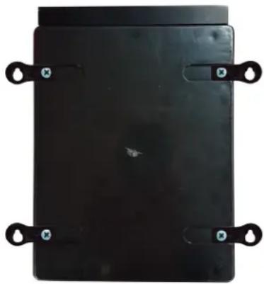
natural_image
Black rectangular object with four metallic clips attached, no visible text or symbolsnatural_image
Simple line drawing of a cylindrical object with a curved hook attached to its top (no text or symbols)Página 10 de 20 Control Station Rev. A
natural_image
Electronic device with green circuit board and connected electronic module (no visible text or symbols)USE SOLO PIEZAS DE REPUESTO ORIGINALES DE HAYWARD

natural_image
Abstract geometric logo with stylized letter H inside a circular frame (no text or symbols)HAYWARD®

natural_image
Exterior view of a black industrial air conditioning unit with digital display and control buttons (no readable text or symbols)
Control Station
MANUAL DO UTILIZADOR
GUARDE ESTE MANUAL PARA REFERÊNCIA FUTURA
www.hayward.fr/en/services/register-your-product
Para seu registo
natural_image
Black electronic device with four numbered labels (4 and 5) on its side, no visible text or symbols beyond labelsnatural_image
Close-up of a transparent plastic mechanical device with four white and beige components, no visible text or symbols.Câmara de medição
natural_image
Four black metal bracket clips with screws attached, arranged in a 2x2 grid (no text or symbols visible)
natural_image
Close-up of a black plastic clip holding a small hole, with a wooden tool inserted (no text or symbols visible)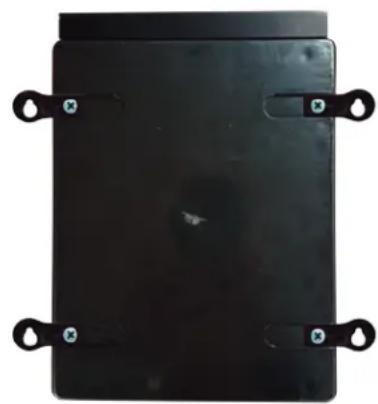
natural_image
Black rectangular electronic component with four metallic clips and mounting holes (no visible text or symbols)natural_image
Pure electrical circuit lines without any symbolsFio Negro (N) = C = Comum
natural_image
Electronic device with green circuit board and connected to a black power supply unit (no visible text or symbols)UTILIZE APENAS COMPONENTES DE SUBSTITUIÇÃO GENUÍNOS HAYWARD
The image contains no discernible text or characters.
[NO TEXT]


6
-
OK OK
OK
→
[NO TEXT]
OKOI


11
2
□
natural_image
Abstract geometric logo with stylized letter H inside a circular frame (no text or symbols)HAYWARD®

natural_image
Exterior view of a black industrial air conditioning unit with digital display and control buttons (no readable text or symbols)
Control Station
ANWENDERHANDBUCH
BEWAHREN SIE DIESES HANDBUCH ZUM SPÄTEREN NACHSCHLAGEN AUF
natural_image
Front view of a black industrial electrical control panel with buttons and display (no readable text or symbols)
natural_image
Black electronic device with four numbered buttons (4 and 5) and a connector, no visible text or symbols on the body.natural_image
Close-up of a transparent medical device with blue and beige components (no visible text or symbols)Messkammer
2 x
Schlauchpumpe
Temperatursonde
ORP-Sonde
natural_image
Four black metal bracket clips with screws attached, arranged in a 2x2 grid (no text or symbols)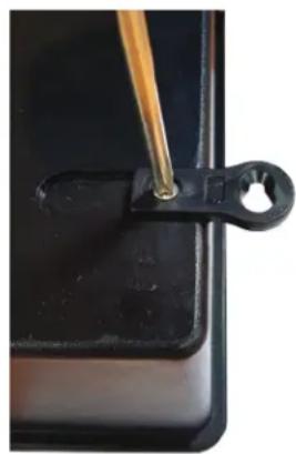
natural_image
Close-up of a black plastic clip holding a small hole, with a wooden tool inserted (no text or symbols visible)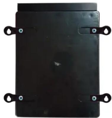
natural_image
Black rectangular electronic device with four black metal clips and mounting holes (no visible text or symbols)natural_image
Pure electrical circuit lines without any symbolsBraunes Kabel (B) = V1 = 1500 U/min Standardeinstellung
Grünes Kabel (G) = V2 = 2400 U/min Standardeinstellung
Rotes Kabel (R) = DI4 = An/Aus
Schwarzes Kabel (S) = C = gemeinsamer Leiter
VERWENDEN SIE NUR ORIGINAL-ERSATZTEILE VON HAYWARD
9
natural_image
Abstract geometric logo with stylized letter H inside a circular frame (no text or symbols)HAYWARD®
natural_image
Exterior view of a black HVAC air conditioner unit with digital display and control buttons (no readable text or symbols)
Control Station
GEBRUIKERSHANDLEIDING


OM UW PRODUCT IN ONZE DATABANK TE REGISTREREN, GAAT U NAAR:
www.hayward.fr/en/services/register-your-product

natural_image
Black electronic device with labeled pins (4 and 5) and a connector, no readable text or symbols beyond labels1 Bedieningskast
2 Aan/uitschakelaar
3 Voedingskabel
4 Zekering 3,15 mA
5 Zekering 630 mA
natural_image
Close-up of a transparent medical device with three white and beige components, no visible text or symbols.Meetkamer
natural_image
Four black metal bracket clips with screws attached, arranged in a 2x2 grid (no text or symbols)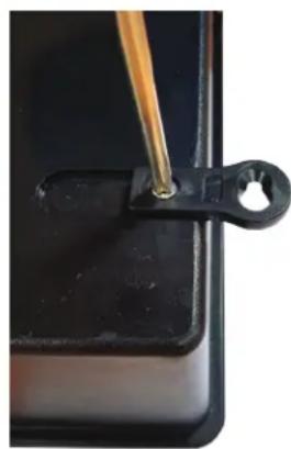
natural_image
Close-up of a black plastic clip holding a small metallic object, with a wooden tool inserted (no text or symbols visible)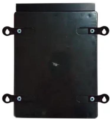
natural_image
Black rectangular object with four side handles and small blue-green circular markers, no visible text or symbols.natural_image
Line drawing of a mechanical clamp or bracket attached to a cylindrical pipe (no text or symbols)PH en ORP sondes installeren op de meetkamer
natural_image
Pure electrical circuit lines without any symbolsBruine kabel (Br) = V1 = 1500 tr/min standaard
Groene kabel (Gr) = V2 = 2400 tr/min standaard
Witte kabel (W) = V3 = 3000 tr/min standaard
Rode kabel (R) = DI4 = Aan/Uit
natural_image
Electronic device with green circuit board and connected to a black power supply unit (no visible text or symbols)ENKEL ORIGINELE RESERVEONDERDELEN VAN HAYWARD GEBRUIKEN.

+
The image contains no discernible text or characters.
- 2018

OK
[NO TEXT]

1 Hulprelais.
9
9 De redox-sonde kalibreren:
natural_image
Abstract geometric logo with stylized letter H inside a circular frame (no text or symbols)HAYWARD®

natural_image
Exterior view of a black industrial air conditioning unit with digital display and control buttons (no readable text or symbols)
Control Station
MANUALE D'USO
CONSERVARE IL PRESENTE MANUALE PER FUTURA CONSULTAZIONE
natural_image
Front view of a black industrial control panel with indicator lights and a logo (no readable text or symbols)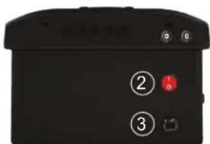
natural_image
Black electronic device with labeled pins (4 and 5) and a connector, no readable text or symbols beyond labelsnatural_image
3D rendered medical device with transparent casing and blue handle (no visible text or symbols)Camera di misura
2 x Pompa peristaltica
Sonda
temperatura
Sonda ORP
natural_image
Four black metal bracket clips with screws attached, arranged in a 2x2 grid (no text or symbols)
natural_image
Close-up of a black plastic clip with a wooden tool inserted, no visible text or symbols
natural_image
Black rectangular electronic component with four metallic clips and mounting holes (no visible text or symbols)natural_image
Pure electrical circuit lines without any symbolsFilo Nero (N) = C = Comune
UTILIZZARE SOLO PARTI DI RICAMBIO ORIGINALI HAYWARD
All HAYWARD products are covered for manufacturing defects or material defects for a warranty period of 2 years as of date of purchases. Any warranty claim should be accompanied by evidence of purchase, indicating date of purchase. We would therefore advise you to keep your invoice.
The HAYWARD warranty is limited to repair or replacement, as chosen by HAYWARD, of the faulty products, provided that they have been subjected to normal use, in compliance with the guidelines given in their user guides, provided that the products have not been altered in any way, and provided that they have been used exclusively with HAYWARD parts and components. The warranty does not cover damage due to frost and to chemicals. Any other costs (transport, labour, etc.) are excluded from the warranty.
HAYWARD may not be held liable for any direct or indirect damage resulting from incorrect installation, incorrect connection, or incorrect operation of a product.
In order to claim on a warranty and in order to request repair or replacement of an article, please ask your dealer.
No equipment returned to our factory will be accepted without our prior written approval.
Wearing parts are not covered by the warranty.
GARANTÍA LIMITADA
BESCHRÄNKTE GARANTIE

- HAYWARD®
- Control Station
- WARNING: Electrical hazard. Failure to comply with these instructions can result in serious injuries or death. THE EQUIPMENT IS INTENDED TO BE USED ONLY IN SWIMMING POOLS
- REGISTRATION
- TO REGISTER YOUR PRODUCT IN OUR DATABASE, GO TO:
- For Your Records
- Note
- GENERAL
- INSTALLATION
- USE ONLY GENUINE REPLACEMENT PARTS
- Wall-mounted installation
- Connecting the water supply points
- Installing the pH and ORP probes on the measuring chamber
- Electrical installation and wiring
- Connecting a heating system (Aux 4)
- Connecting the ORP option (Optional)
- Assigning speeds
- Connecting the Wifi option
- Installing the screen wall-mounting kit (not supplied)
- Chemical water balance
- Saturation index
- OPERATION
- Filtration
- Setting the pump type
- Lighting
- Auxiliary relays.
- Setting the Wifi module
- Setting the redox level
- SERVICING
- Servicing the probes
- Wintering
- Probe storage
- TROUBLESHOOTING GUIDE
- No display
- Excessive chlorine
- Impossible to attain a free chlorine level of 0.8 ppm
- Alarm AL3: dosing pump stopped
- Chlorinator display indicates FLOW
- Para seu registo
- VERWENDEN SIE NUR ORIGINAL-ERSATZTEILE VON HAYWARD
- OM UW PRODUCT IN ONZE DATABANK TE REGISTREREN, GAAT U NAAR:
- PH en ORP sondes installeren op de meetkamer
- Hulprelais.
- De redox-sonde kalibreren:
- GARANTÍA LIMITADA
- BESCHRÄNKTE GARANTIE
Brand : HAYWARD
Model : Control Station
Category : Swimming Pool