
CW 3 Klean!Star - Car Wash Kärcher - Free user manual and instructions
Find the device manual for free CW 3 Klean!Star Kärcher in PDF.
| Product type | Vehicle washing station (wash gantry) |
| Brand | Kärcher |
| Model | CW 3 Klean!Star |
| Washing height | 2100 to 2900 mm depending on version |
| Total height | 2930 to 3730 mm depending on version |
| Total width (with side brushes) | 4040 mm |
| Frame depth | 1600 mm |
| Track width (rails) | 2550, 2700 or 2800 mm |
| Power supply | 400 V / 50 Hz, connected load 10-16 kW, max. fuse 35-50 A |
| Water connection | Nominal width 1 inch, flow pressure 0.4-0.6 MPa, max. temperature 50 °C |
| Compressed air connection | Nominal width 1/2 inch, pressure 0.6-0.8 MPa |
| Main functions | High-pressure washing, rotating side brushes, roof brush, wheel washing device, blower drying, detergent and wax application |
| Sound level (washing with drying) | 87 dB(A) |
| Sound level (dry operation) | 91 dB(A) |
| Care and maintenance | Daily cleaning of nozzles/screens, check of photoelectric barriers and limit switches; weekly brush maintenance; semi-annual and annual maintenance by after-sales service |
| Safety | Emergency stop buttons, limit switches, safety valve, splash protection, anti-tilt safety |
| Spare parts and repairability | Exclusive use of original Kärcher parts; accessories and spare parts available at www.kaercher.com |
| Warranty | Warranty according to national legal conditions, coverage of material or manufacturing defects |
Frequently Asked Questions - CW 3 Klean!Star Kärcher
User questions about CW 3 Klean!Star Kärcher
0 question about this device. Answer the ones you know or ask your own.
Ask a new question about this device
Download the instructions for your Car Wash in PDF format for free! Find your manual CW 3 Klean!Star - Kärcher and take your electronic device back in hand. On this page are published all the documents necessary for the use of your device. CW 3 Klean!Star by Kärcher.
USER MANUAL CW 3 Klean!Star Kärcher

Chairman of the Board of Management

S. Reiser
Manager Regulatory Affairs & Certification
71364 Winnenden (Germany)
Tel.: +49 7195 14-0
Fax: +49 7195 14-2212
Winnenden, 2022/11/01
Contents
General notes 24
Environmental protection 24
Safety instructions 24
Intended use 26
Water connection 26
Accessories and spare parts. 27
System description 27
Control elements. 30
Display description 32
Start-up 34
Operation 34
Shutting down 37
Care and service. 37
Troubleshooting guide 42
Warranty 45
Technical data 45
Declaration of Conformity 46
General notes
Read these original operating instructions and the safety instructions chapter before using the device for the first time. Act in accordance with them.
Keep them safe for future reference or for future owners.
Environmental protection

The packing materials can be recycled. Please dispose of packaging in accordance with the environmental regulations.

Electrical and electronic devices contain valuable, recyclable materials and often components such as batteries, rechargeable batteries or oil, which - if handled or disposed of correctly - can pose a potential danger to human health and the environment. However, these components are required for the direct operation of the device. Devices marked by this symbol not allowed to be disposed of together with the household dish.
Notes on the content materials (REACH)
Current information on content materials can be found at: www.kaercher.de/REACH
Safety instructions
Dangers can be presented to the operator and other persons if the device is incorrectly operated or misused:
High water pressure
High electrical voltage
- Compressed air
Detergent
To avoid danger to persons, animals and property, read the following documents before operating the system:
- The operating instructions, including all safety instructions
The respectively applicable national regulations - The safety instructions provided with the detergent used. Ensure the following:
- That you have understood all notes and instructions
- That all users of the system are notified of the instructions and have understood them
All persons working on the erection, commissioning and operation of the system must:
- Be appropriately qualified
- Know and adhere to the operating instructions
- Know and adhere to the applicable regulations
In self-service operation, ensure that clearly visible notices are present informing all users with regard to:
- Potential dangers
- Safety devices
- Operating the system
The owner/operator of the washing bay is to create work instructions based on these operating instructions, the local conditions and the personnel conditions. The operating instructions are to be made available by providing copies or hanging signs with corresponding content in the workplace.
Hazard levels
△DANGER
- Indication of an imminent threat of danger that will lead to severe injuries or even death.
WARNING
- Indication of a potentially dangerous situation that may lead to severe injuries or even death.
CAUTION
- Indication of a potentially dangerous situation that may lead to minor injuries.
ATTENTION
- Indication of a potentially dangerous situation that may lead to damage to property.
Regulations and guidelines
In the Federal Republic of Germany, the following regulations and guidelines apply to the operation of this system (available from Carl Heymanns Verlag KG, Luxemburger Straße 449, 50939 Cologne):
- Accident prevention regulations "General regulations" BGV A1
Vehicle washing plant safety EN 17281
German work safety directive (BetrSichV)
Vehicle washing plants
Only persons familiar with the work, the operating instructions and the dangers associated with the system are permitted to operate, monitor, care for and inspect car wash systems.
Waste water containing mineral oil
ATTENTION
Environmental pollution through vehicles
Escaping oils.
Protect the ground and dispose of old oil in an environmentally-friendly manner.
Do not allow gear oil and waste water containing mineral oil to enter the soil or waterways.
Treat the waste water before channelling it into the sewage system.
Observe the locally applicable statutory regulations and waste water treatment regulations.
Self-service
In self-service systems, a person must always be available during operating periods, who is familiar with the washing bay and can take or initiate the measures necessary for preventing potential dangers in the case of a system malfunction.
Clearly visible instructions on the operation and intended use of the washing system must be provided at the washing bay for the users of the washing system.
Maintenance and servicing
The washing bay must always be shut down when performing maintenance and servicing work.
WARNING
Risk of injury from machine movements
Switch the system off before performing maintenance and servicing work.
Secure the main switch with a padlock to prevent it from being switched on again.
Operation with detergent
WARNING
Danger from substances in detergents that present a hazard to health
Observe the safety data sheets for the detergents used.
Adhere to the prescribed safety measures.
Wear the prescribed protective clothing such as safety goggles and protective gloves.
ATTENTION
Increased risk of corrosion through the use of unsuitable cleaning agents
Do not use the following cleaning agents in the system:
Detergents intended for cleaning the washing hall.
Detergents intended for externally cleaning the washing bay.
Acidic cleaning agents.
Cleaning agents applied to the vehicle using a separate device (e.g. wheel cleaner).
Water treatment agents.
Entering the portal washing station
△DANGER
Danger through entering the portal washing station
Prohibit unauthorised persons from entering the portal washing station.
Erect suitable permanent signage indicating prohibited entry.
Risk of slipping
ATTENTION
Risk of slipping on wet surfaces
Wear suitable shoes when entering the system and exercise care when walking.
Erect suitable permanent signage informing customers of the danger of slipping.
Operating the system
△WARNING
Danger through incorrect operation
Persons operating the system must:
Be instructed in the correct handling of the system,
Have provided verification of their ability to operate the system, Be explicitly nominated to operate the system.
The operating instructions must be accessible to all operators.
The system may not be operated by persons under 18 years of age. This does not include supervised trainees of 16 years of age or more.
WARNING
Risk of tripping over objects or supply lines lying on the ground
Remove all objects lying in the washing station before starting the system.
Danger of frost
△WARNING
Risk of injury or damage due to the formation of ice in the system
Drain all water from the system if there is a danger of frost.
Keep all footpaths slip-free (e.g. floor heating, gravel).
Workstation
The system is started via the control panel or via a wash card/ code reader.
- The occupants must leave the vehicle before washing.
- Entering the system before washing has finished is prohibited.
Danger sources
General dangers
△DANGER
Risk of injury from escaping compressed air, high-pressure water at nozzle outlets and propelled dirt particles or similar in the vicinity of the rotating brushes!
Dirt particles or loose objects can injure persons or animals when propelled off the vehicle.
Compressed air or high-pressure water can remain pressurised even when the system is switched off.
Keep the hall floor free of loose lying objects.
Exercise care when operating the compressed air system and the high-pressure system.
Wear suitable safety goggles when performing maintenance work.
Risk of explosion
△DANGER
Risk of explosion
Do not operate the system in the vicinity of potentially explosive spaces. Systems specifically designed for this, and labelled accordingly, are exempt from this stipulation
Do not use explosive or poisonous substances as cleaning agents, e.g.:
Petrol
Heating oil or diesel fuel
Solvents
- Liquids containing solvents
Acids
- Acetone
Note
Contact the manufacturer if you are unsure.
Hearing damage
The noises emitted by the system are not hazardous for the washing customers due to the short exposure time.
Note
The sound level at the entry side during dry operation is 91 dB(A).
WARNING
Risk of hearing damage to the operating personnel during drying mode
Wear hearing protection during drying mode.
Hearing damage due to high volume in the machine room
Wear suitable hearing protection when staying in the machine room.
Electrical hazards
△DANGER
Danger of electric shock
Never touch electrical components and cables with wet hands.
Ensure that the electrical connection cables or extension cable are not damaged by being driven over, crushed, yanked or similar.
Protect the cables from heat, oil and sharp edges.
Never point a water jet at electrical devices or systems.
Protect all live components in the work area from water jets.
Connect the system only to correctly earthed power sources.
Allow only qualified electricians to work on electrical components of the system.
Substances harmful to health
△DANGER
Danger due to harmful substances
Be sure to observe the information and notes provided with the detergent.
Never drink water expelled from the system! The water is not of drinking water quality due to the added cleaning agents.
Observe the anti-bacterial regulations of the treatment system manufacturer when using processed water for operating the system.
Ensure that materials not normally present during exterior cleaning of vehicles (e.g. heavy metals, pesticide, radioactive materials, faeces or infectious materials) do not enter the washing bay.
Danger due to power failure
Design measures are to be taken to ensure that uncontrolled restarting of the system after a power failure is impossible.
Environmental hazard due to waste water
Observe the local waste water disposal regulations.
Servicing and monitoring
The corresponding instructions must be followed to ensure safe operation of the system and avoid dangers during maintenance, monitoring and inspection.
Maintenance and servicing
Maintenance work must be performed as specified by the manufacturer by a technically qualified person at the specified regular intervals. Observe the applicable regulations and safety requirement. Allow only qualified electricians to work on the electrical system.
WARNING
Risk of injury from machine movements
Switch the system off before performing maintenance and servicing work.
Secure the main switch with a padlock to prevent it from being switched on again.
WARNING
Risk of injury from pressurised compressed air reservoirs and lines after the system has been switched off
Depressurise the system before performing any work on the system.
Check the pressure gauge at the maintenance unit to ensure that the system is depressurised.
△WARNING
Risk of injury from the high-pressure system after the system has been switched off
Depressurise the high-pressure system before performing any work on the system.
Monitoring
This washing bay must be inspected by a technically qualified person to ensure a safe condition before initial commissioning and then at half-yearly intervals at the very least.
This inspection includes especially:
- A visual inspection for all externally visible signs of wear and tear or damage
- Function test
- The completeness and effectiveness of all safety devices at self-service stations must be checked daily before the start or operations, or as required on monitored systems but always at least once a month.
Use only original parts
Use only original manufacturer spare parts or parts recommended by the original manufacturer, otherwise all warranty claims will be invalidated.
Adhere to all safety instructions and application instructions provided with these parts.
This applies to:
- Spare parts and wearing parts
- Accessories
- Operating materials
Detergent
Safety devices
The high-pressure pumps for the supply of the underbody washing unit and the high-pressure wash have the following safety devices.
Safety valve
The safety valve opens when the permissible operating pressure is exceeded and the water flows into the open.
Intended use
This washing bay is exclusively intended for external cleaning of passenger vehicles with standard equipment and closed delivery vehicles.
Adherence to the intended use also includes:
- Adherence to all information provided in these operating instructions.
Adherence to the inspection and maintenance instructions.
ATTENTION
Risk of damage to vehicles when using the CareTouch brushes
Equip the system with a high pressure attachment kit or pre-wash the vehicles when using the CareTouch brushes.
Be aware of the dimensions
To prevent damage to vehicles and the washing bay, only passenger vehicles and closed delivery vehicles conforming to the specified dimensional limits may be cleaned, see chapter Technical data.
Water connection
A category 5 mains isolation must be installed between the system and the drinking water network to protect the drinking water network according to EN 1717.
Erection
The system must be erected by qualified technical personnel.
The locally applicable safety regulations (e.g. clearances between the system and buildings) must be adhered to during erection.
Foreseeable misuse
Any type of improper use is prohibited.
The operating personnel are liable for hazards resulting from incorrect use. Usage for other purposes than those described in this documentation is prohibited.
ATTENTION
Material damage to vehicles and the system if the vehicle dimensional limits are not adhered to
Adhere to the specified vehicle dimensional limits, see chapter Technical data.
The portal washing station is not suitable for cleaning:
- Special passenger vehicles, e.g. vehicles with roof and alcove attachments projecting above the windscreen at the front or above the rear window at the rear
- Construction machines
- Vehicles with trailers
- Two-wheel and three-wheel vehicles
- Vehicles with double tyres / twin tyres
Pick-ups (optional) - Convertibles with an open roof
- Convertibles with a closed roof but without manufacturer verification of washing system suitability
If these instructions are not followed, the system manufacturer accepts no liability for any resulting
personal injury,
material damage,
injuries to animals.
Unsuitable detergents
ATTENTION
Increased risk of corrosion through the use of unsuitable cleaning agents
The following cleaning agents may not be used in the system:
- Detergents intended for cleaning the washing hall.
- Detergents intended for externally cleaning the washing bay.
Acidic cleaning agents. - Cleaning agents applied to the vehicle using a separate device (e.g. wheel cleaner).
Water treatment agents.
Accessories and spare parts
Only use original accessories and original spare parts. They ensure that the appliance will run fault-free and safely.
Information on accessories and spare parts can be found at www.kaercher.com.
System description
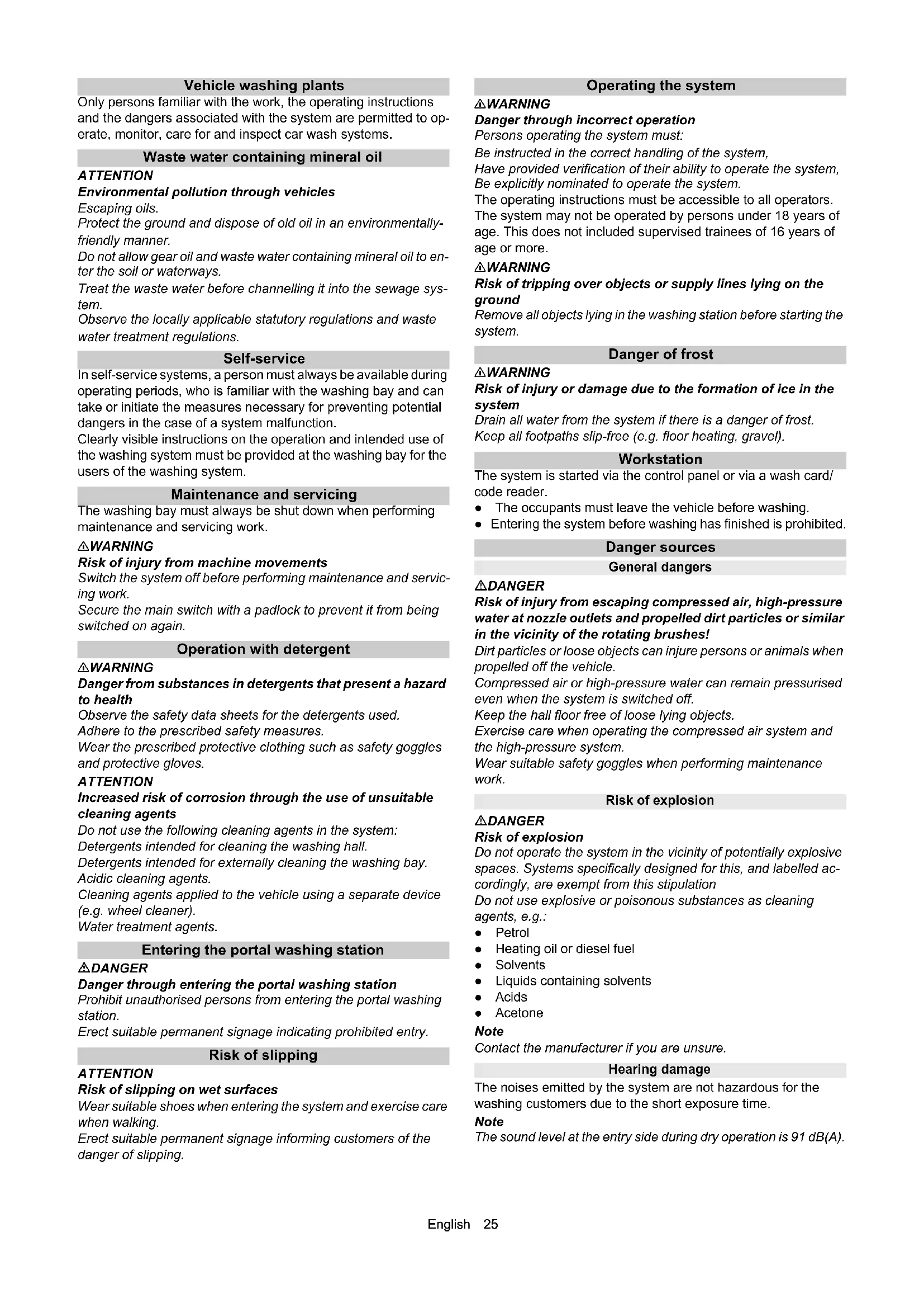
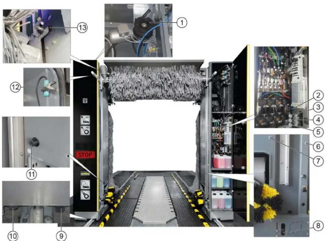
Overview of the entry side of the system

Pillar 1
② Brush watering nozzles (circuits A1 / A2 / A3 optional instead of C3)
③ Roof brush
④ Pillar 2
(5)High-pressure valves
Pneumatic valve block
Dosing pumps
⑧ Maintenance unit
Pressure reducer
10Cleaning and care agents
Chassis and suspension
12Nozzles for fresh water, chemical drying aids, wax (circuit A1)
13Nozzles for wheel rim foam/prespraying of wheel rims
⑭ Wheel washing unit
High pressure nozzles for wheel washer/wheel well cleaning
16 Nozzles for foam, insects, intensive Basic (circuit B2)
17Nozzles for processed water, shampoo (circuit B1)
18High-pressure nozzles
(19)Guide rails
20 Washing phase display
② Positioning light
Side brush 2
②Roof brush
③ Nozzles for polishing (circuit C3)
4Nozzles for fresh water, chemical drying aids, wax (circuit C2)
(5) Nozzles for processed water, shampoo (circuit C1)
(6) Roof blower motor
7Side brush 2 rotation motor
Roof drier
⑨Side brush 1 rotation motor
⑩ Side brush 1
Standard equipment
Side brushes
The rotating side brushes clean the vehicle at the sides, front and rear.
Roof brush
The rotating roof brush removes dirt from the top of the vehicle.
Wheel washing unit (circular broom)
The washing bay is equipped with two wheel washing units for thorough wheel cleaning. The position of the wheels is determined by a light sensor.
The rotating brushes are pressed against the wheel rim by pneumatic cylinders.
The brushes are watered by a nozzle mounted in the centre of each brush.
Note
An optional height-adjustable wheel washing unit is available.
Nozzles and spray arches
Processed water and fresh water is sprayed onto the vehicle by nozzles and spray arches.
Cleaning agents and care agents are mixed into the water according to the washing program.
A1 = Fresh water, chemical drying aid (CTH), wax
A2 = Processed water, shampoo
A3 = Polishing (optional, instead of C3)
B1 = Processed water, shampoo
B2 = Foam, insects, intensive Basic
C1 = Processed water, shampoo
C2 = Fresh water, chemical drying aid (CTH), wax
C3 = Polishing
G = Prespray wheel rims
L = Tar remover
K = Wheel gloss
H 2 = High pressure wheel wash
H 3 = High-pressure side nozzles
H4 = High-pressure roof nozzles
Foam wash
The cleaning agent for pre-cleaning is applied as a foam to extend the contact time.
Dirt traps
The dirt traps retain particles that might clog the nozzles.
Dosing pumps
The dosing pumps mix cleaning and care agents into the water.
Dryer side nozzles
The air required for blowing the sides of the vehicle dry flows out of the drier nozzles.
Roof drier
The drier blower bars are moved along the contour of the vehicle. The air flow required for drying the vehicle is generated by integrated fans.
Positioning light
The positioning light has the following functions:
For positioning the vehicle before washing.
For indicating the exit direction after washing.
For indicating faults.
Light sensors
The light sensors provide the following information:
The position and contours of the vehicle.
The position of the vehicle wheels.
Cleaning and care agents
The cleaning and care agent canisters and dosing pumps are located in pillar 2.
A maximum of 8 canisters can be installed in pillar 2.
The supply can be optionally provided from the technical room if more canisters are required.
The suction hoses, canisters and dosing pumps are all labelled with the same colour Labelling of the dosing pumps.
| Name | Description Consump- | tion | Order no. |
| RM 896 | Vehicle Pro Klear! RIM* 15-2 | 5ml 6.296-0 | 77.0 |
| RM 890 | Vehicle Pro Klear! Prewash* | 10-14ml 6.2 | 96-003.0 |
| RM 891 | Vehicle Pro Klear! Brush* 7- | 10ml 6.295- | 95.0 |
| RM 892 | Vehicle Pro Klear! Foam* 8- | 10ml 6.295- | 98.0 |
| RM 893 | Vehicle Pro Klear! Dry* 8-12ml | 6.296-001.0 | |
| RM 894 | Vehicle Pro Klear! Glow* 10- | 15ml 6.295- | 993.0 |
| RM 837 | Vehicle Pro Klear! Plus** | 15ml | 6.295-779.0 |
- Container capacity 10 litres
- Container capacity 20 litres
Type plate
The major device information is specified on the type plate.
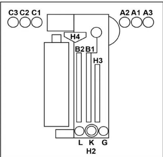
Control cabinet
The system control cabinet is located at the main supply distributor.
Supply distributor
The main switch for the system is located on the main supply distributor.
The main supply distributor is located outside the washing bay, in the technical room or at suitable location in the vicinity of the washing bay.
Supply distributor
2Key switch, see ABS payment system
-0=Systemoff
-1=Operation via wash card reader
- 2 = Operation via wash card reader and control panel (display)
③ Main switch, see Main switch
Emergency off
In the event of danger to persons, equipment or animals, the system must be switched off immediately by pressing the "EMERGENCY OFF" button.
"EMERGENCY OFF" buttons are located:
- On the wash card/code reader.
On the control panel. - Optionally at the washing hall entrance if the control panel or wash card/code reader are not located at the entrance.
Operating station
The washing bay is supplied with:
A control panel with display
- A wash card/code reader (optional)
Tilt protection
A mechanical retainer keeps the system on the guide rails, even in the case of incorrect behaviour by the washing customer.
Options
Wash card reader/code reader
A wash card reader or code reader is used for operating the washing bay in self-service mode.
Note
The wash cards/codes required for operating the system are programmed on the respective system.
Process water connection
The process water connection allows rain water or recycled water to be used as a partial replacement for fresh water.
Planet wheel washing unit
The planet wheel washing unit is equipped with 3 brushes instead of a circular broom.
Height-adjustable wheel washing unit
The wheel washing units can be additionally equipped with a height adjustment mechanism.
Wheel well cleaning
The wheel wells and sills of the vehicle are cleaned by water jets from 2 additional nozzles per washing direction.
Underbody washing unit
The vehicle underside can be washed with the underbody washing unit. For this, water is sprayed at high pressure over the entire underbody via two pivoting nozzle pipes.
Prespraying (remove insects)
Foam is applied to the front half of the vehicle by the prespraying nozzles. The foam is generated from water, prespraying agent and compressed air.
Intensive Basic
Pre-cleaning chemicals are applied to the vehicle by stationary nozzles.
The foam is generated from water, prespraying agent and compressed air.
Wheel rim foam
Compressed air is used to spray a water-cleaning agent mixture onto the wheel rims via 2 stationary foam nozzles.
High-pressure wash
The high-pressure wash removes coarse dirt from the surface of the vehicle. High-pressure cleaning minimises the danger of scratching from sand grains or similar abrasives and makes a significant contribution to preserving the paintwork during cleaning. Various different versions are available:
- Working pressure 16 bar (1.6 MPa)
- Working pressure 60 bar (6 MPa)
- Working pressure 70 bar (7 MPa), on-board high-pressure pump (in the portal)
Foam wax
Foam wax is applied to the vehicle by the drying aid nozzles before the drying process.
Cold wax
Water mixed with wax is sprayed onto the vehicle via the cold wax nozzles. Two different types of cold wax (wax 1 and wax 2) can be selected.
Cleaning agent heater
The cleaning agent heater is located in the cleaning agent supply in pillar 2.
Frost protection device
The washing bay can be equipped with a frost protection device: If there is a danger of frost, the water is blown out of the piping system automatically.
This blowing process is controlled by a thermostat.
Reverse osmosis system
Demineralised water (from an on-site system or optionally available reverse osmosis system) or fresh water dosed with drying aid is sprayed onto the vehicle via the drying aid nozzles.
Foam polishing
A compressed air foamed mixture of water and cleaning agent is sprayed onto the vehicle via 2 stationary nozzles. This is followed by a polishing procedure with the washing brushes.
Safety switch
Safety switches are required if the required safety clearances between the washing bay and permanent fixtures (e.g. walls, pillars, sinks) cannot be maintained. The safety switches prevent persons from being crushed between the system and the wall. The washing bay stops immediately if a safety switch touches an obstacle.
Note
If the system is stopped by a safety switch, determine the cause if this hand have the safety switch reset by an authorised technical specialist.
Splash guard
The splash guard protects the areas adjacent to the washing station from sprayed dirt and splash water emitted by the rotating side brushes.
The splash guard is attached to the outer surfaces of the chassis and suspension as well as the pillars.
Bollard protection
The purpose of the bollard protection is to ensure central alignment of the vehicle. They prevent the vehicle from being parked too far away from the centre.
Remote reset
The Reset function allows the wash gantry to be moved to the initial position remotely with a command via an interface. The function can be enabled via a separate parameter in the system control.
- This function must only be enabled in countries or at locations where this function is permitted.
- Video surveillance must be installed on site, covering the entire area of the washing hall or the entire travel path of the system, and any regulations applicable in the country/municipality where the system is installed must be applied.
- The person who performs the remote reset must first ensure via the video surveillance that there are no persons in the travel path of the system. If a person then requests the command, that person must confirm that the system and its travel path are completely free by acknowledging a safety notice (e.g. pop-up window).
- The person who integrates the system into his system, e.g. via the Internet, is responsible for the required security or cybersecurity and a risk assessment must be carried out on the system.
Gate control
The on-site gate control is actuated by the passenger vehicle portal controller with the correct signals according to the washing sequence.
A distinction is made between summer gate control and winter gate control.
Summer gate control
The gates are open before washing starts.
The vehicle can drive in.
The gates are closed when washing starts.
- The gates are opened when washing ends and remain open.
Winter gate control
- The entry gate is closed before washing starts and must be opened to allow the vehicle to drive in. This is done by e.g. inserting a wash card into the wash card reader.
- The gates are closed when washing starts (e.g. by pressing the "Start" button on the wash card reader).
- The gates are opened when washing ends and are closed again after the vehicle has exited.
Control elements
Emergency off
In the event of danger to persons, equipment or animals, the system must be switched off immediately by pressing the "EMERGENCY OFF" button.
"EMERGENCY OFF" buttons are located:
- On the wash card/code reader.
- On the control panel.
- Optionally at the washing hall entrance if the control panel or wash card/code reader are not located at the entrance.
Main switch
The main switch is located at the main supply distributor. Set the main switch to "1" to switch the system on.
ABS payment system
At the key switch on the main supply distributor, see Supply distributor can be used for selecting the operating stations from which washing programs can be started.
- Position 0: Programme start not possible
- Position 1: Programme start possible at the wash card/code reader
- Position 2: Programme start possible at the wash card/code reader and at the control panel
Wash card/code reader
Depending on the version of the Wash card/code reader, the washing program can be selected as follows:
- Entry via a keypad.
The program specified on the wash card. - Entry of a code number.
Note
Further information is provided in the separate operating instructions for the wash card/code reader.
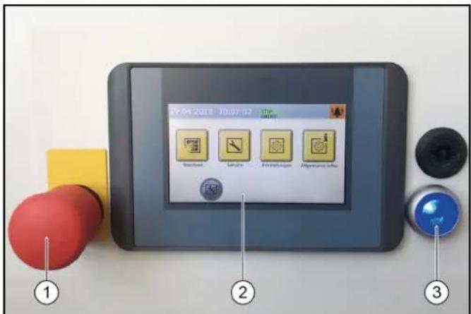
Control panel
① Emergency off button
②Display
③ Control voltage/initial position button
Dosing pumps
The cleaning and care agents are added to the water by the dosing pumps located in pillar 2.
The assignment of the dosing pumps is by way of example only. Dosing pumps 1-4 are assigned as shown in a standard system. 7 different cleaning and care agents can be selected for dosing pumps 5-8.
Dosing pump
②Shampoo dosing pump
③ Foam dosing pump
④ Wax 1 dosing pump
⑤ Pre-cleaning dosing pump (insects)
⑥ Wax 2 dosing pump
⑦ Wheel cleaner dosing pump (wheel rim foam)
⑧ Polishing dosing pump
The dosing pumps add cleaning and care agents to the washing water according to the washing program and the equipment in the system.
Note
The dosing quantities are adjusted optimally by the installation technician during initial commissioning. Changes to these settings are not usually necessary.
Labelling of the dosing pumps
Note
The positioning of the dosing pumps is system-dependent.
| Dosing pump Cleaning and care agents | |
| DP A | Drying aid |
| DP B | Shampoo |
| DP C | Active foam |
| DP D | Wax 1 |
| DP E | Polish 1 |
| DP F | Wheel cleaning |
| DP G | Wax 2 |
| DP H | Tyre gloss |
| DP I | Insect pre-cleaning |
| DP K | Polish 2 |
| DP L | Intensive Basic |
Adjusting the dosing amount

(1) Venting button
(2) Venting lever
③Dosing amount adjustment knob
ATTENTION
Damage to the dosing pump due to dry running
Only adjust the dosing amount when the dosing pump is running.
- Pull out the dosing amount adjustment knob.
- Alternately press and release the ventilation button while turning the adjustment knob to the desired setting.
- Release the ventilation button.
- Press in the dosing amount adjustment knob.
Vent the dosing pump
The system compressed air supply must be in operation.
Venting button
(2) Venting lever
③Dosing amount adjustment knob
- Turn the venting lever anticlockwise as far as it will go.
- Set the dosing amount to 100% .
- Press the ventilation button repeatedly until the detergent comes out of the venting line on the underside of the dosing pump without bubbles.
- To set the dosing amount back to the desired value, see Adjusting the dosing amount.
- Turn the venting lever clockwise as far as it will go.
Display description
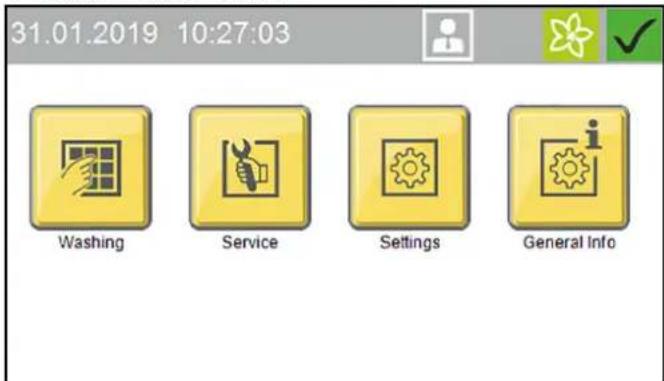
Start display
31.01.2019 10:27:03


Washing
Service
Settings
General Info
Note
The language is set during initial commissioning and can be changed via the Settings / General menu.
The display can be used for e.g. making system settings, making settings for the display and displaying system information.
Status bar
①
2
07.06.2018 10:04:08
(3)
(4)
(5)
(6)
①Date
②Time
③ Currently logged-in user
4Service date is due
Current season (if this function is enabled)
Current system status
Description of symbols
The following symbols are shown on the display, depending on the current menu or status of the system

System ready for operation

System malfunction

Home button
The Home button us used to navigate back to the previous menu from a submenu.

Logged in with normal User access rights

Logged in with Cleaning agent supplier access rights

Logged in with Operator access rights

Logged in with Service access rights

Spring seasonal washing program set

Summer seasonal washing program set

Autumn seasonal washing program set
Winter seasonal washing program set
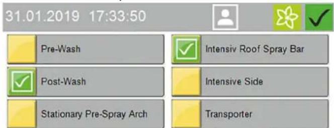
Washing
The Washing menu is used for selecting and starting programs and additional programs.
The currently running program can be interrupted and the progress in percent can be displayed.
31.01.2019 17:25:24


1)Programm 1

4|Programm 4

2|Programm 2

5|Programm 5

31Programm 3

6|Programm 6

Side 1/2


Start washing program, see Start the program on the display.
Service
The Service menu allows manual functions to be executed and the manual frost protection device to be started.
31.01.2019 12:23:28


Manual Operation
Diagnosis

Service
The Service menu contains the following submenus:
- Manual mode (portal manual functions, manual starting of the frost protection device, manual water system functions)
- Diagnostics (Operators and Service personnel only) This calls up self-test functions for the system
Settings
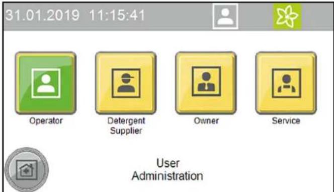
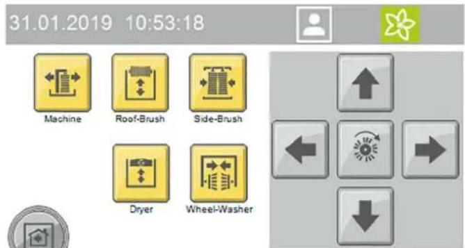
The Settings menu contains the user management functions and allows system settings to be made.
31.01.2019 11:57:35


User Administration
Wash-Program Settings
Machine
General

Settings
The Settings menu contains the following submenus:
- User administration
- Wash program settings (pre-cleaning portal speed, brushes, care and drying, seasonal settings)
- System (cleaning agent, water supply, gate operation, customer text priority display)
- General (set date, time and opening times, select language, display system information)
General Info
This menu can be used for displaying system reports and showing the current filling levels of the cleaning agents.
31.01.2019 17:18:35


Wash-Counter

Operating Hours
Maintenance
Diagnostic
Liquid Level
Detergents

General Info
The General Info menu contains the following submenus:
- Wash counter (Operators only) - display of the completed and interrupted washes
- Operating hours
- Maintenance diagnostics - interval to the next servicing, system information, error memory, event memory
- Cleaning agent filling levels - percentage filling levels of the cleaning agents (option)
Messages on the display
The following push messages can be shown on the display when the system is in operation.
Critical fault
Critical fault
SB2 Position not logical

Endpos. In-Out Simultaneous
Check Limit Switches
Inform Technical Service
F0212 31.01.2019 14:35:29

Message
2/2


△DANGER
Danger from a critical fault
Switch the system off and notify the Service department.
Critical faults may only be corrected by persons trained in the system servicing tasks.
If multiple errors are present, these are displayed one after another.
You can switch between the displays using the arrow keys.
Malfunction
Malfunction
Dryer LightbarrierMiddle
Lightbarrier Blocked
Check, Clean Lense

Malfunctions are errors occurring during the washing program. The washing program is interrupted and can be resumed after elimination of the malfunction.
If multiple malfunctions are present, these are displayed one after another.
You can switch between the displays using the arrow keys.
A detailed description of troubleshooting is provided in chapter Troubleshooting guide.
Event
Event
Position Right Wheelwasher
Not In Initial Position
Stroke Mechanism, Air Supply
Reset (Blue Button)
E5017 31.01.2019 14:24:48

Message 2/2


An event is an error occurring when no washing program is active.
If multiple events are present, these are displayed one after another.
You can switch between the displays using the arrow keys.
A detailed description of troubleshooting is provided in chapter Troubleshooting guide.
System not in initial position
31.01.2019 17:09:45


Machine Not In Initial Position
Press Button To Return Machine Into Home Position

This message appears when one or more power units are not in their respective initial position.
Note
Press and hold the button (>2 seconds) or press and hold the blue button (>2 seconds) to move the system to the initial position.
Service required
31.01.2019 13:42:22


Service Interval
Reached
Please Scedule Maintenance


This message appears when a service date is due.
Note
Contact the Service to arrange a servicing appointment.
Start-up
- Open the stop valves for water and compressed air.
- Set the main switch at the main supply distributor to "1".
- Press the blue control voltage/initial position button on the control panel.
System ready for operation. The vehicle to be washed can now be driven in.
Operation
DANGER
Danger from moving system components
Switch the system off immediately using the emergency off button in the case of danger to persons, property or animals.
ATTENTION
Risk of damage to the vehicles through inadequately removed cleaning agent
If a malfunction occurs in the washing bay after application of the cleaning agent, you must remove the cleaning agents by spraying thoroughly with water after switching off the system to prevent paint damage due to an excessively long cleaning agent exposure time.
Note
In self-service systems, a person must always be available during operating periods who is familiar with the washing system and can take or initiate the measures necessary for preventing potential dangers.
Switching on again after an emergency off
Note
Correct the reason for actuating the emergency off button before switching the system on again.
Persons or animals must not be present in the work area. Any vehicles present must be driven out of the system.

Emergency stop button
2Control voltage/initial position button
1. Unlock the emergency off button by pulling it.
2. Press the blue control voltage/initial position button on the control panel.
In the initial position, the upper green "Forwards" lamp on the positioning light lights up. The system is now ready for operation, the vehicle to be washed can now be driven in.
Log in the user on the display
- Select Settings/User Administration in the main menu.
The available users are displayed.
- Select the desired user.
The dialogue for entering the code opens.
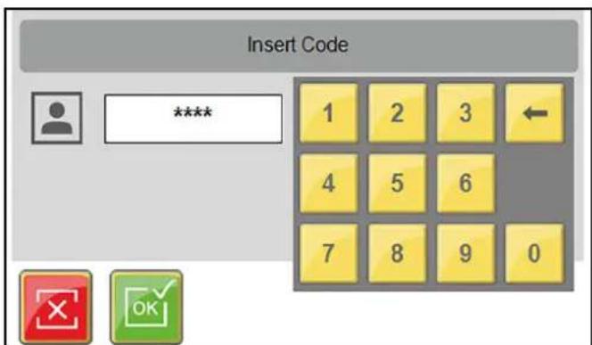
- Enter and confirm the code.
The symbol for the currently logged-in user is displayed in the top line.
Note
The user level switches automatically back to the normal User level after 30 minutes of inactivity.
Preparing the vehicle
ATTENTION
Damage to the system and the vehicle
To prevent damage to the vehicle, take care to ensure that the following measures are taken before starting the system.
- Close all windows, doors and sunroofs.
- Push in the antennas, fold them in towards the rear or remove them.
- Fold in any large or wide projecting mirrors.
-
Check the vehicle for any loose vehicle parts and remove these, e.g.:
-
Trim strips
- Spoiler
Bumpers
Door handles - Exhaust pipes
Wind deflectors
Tarpaulin ropes
Rubber seals - Externally mounted sun visors
Luggage racks
Driving in the vehicle
The positioning light assists the customer in positioning the vehicle correctly.
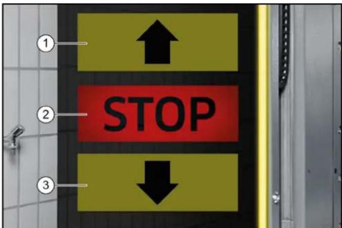
1Drive forwards
②Stop, position OK
③Drive in reverse
1. Position the vehicle straight ahead and centrally between the guide rails.
After positioning
- Shut down the engine.
- Engage one gear.
- With an automatic transmission, select "P".
- Apply the handbrake.
- Check that all instructions from Preparing the vehicle have been followed.
- Exit the vehicle (all persons).
- Start the washing programme depending on the start type.
Starting the program
At the wash card/code reader
Note
Operation with a wash card/code reader is described in the separate operating instructions for the wash card/code reader.
Start the program on the display
- Press the "Wash" button.
- Select the desired washing program.


- Select the desired options and confirm with "OK".

- Start the washing program.
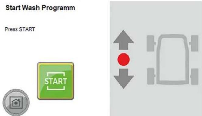
- The following manual functions can be executed via the display while a washing program is running:
a Lock/raise dryer
b Lock/raise roof brush
c Lock/outwards movement of the side brushes
d Stop the wheel brushes
Press the "Information" button to show the program progress display.
Interrupting the currently running program

- Press the "Stop" button.
The program is interrupted.

- Press the "Start" button to resume the program.
Programme end
After the programme has finished, the positioning light indicates whether the vehicle should be driven forwards or backwards out of the system.
- Drive the vehicle out of the system.
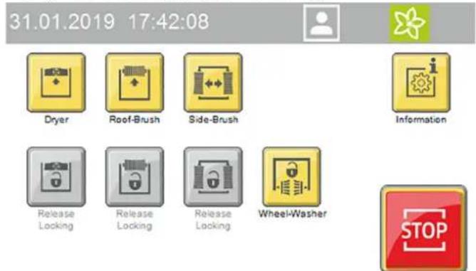
Manual mode
Manual functions can be performed with the following assemblies:
- Portal - move
- Roof brush - raise and lower, switch on and off
- Side brushes - move in and out, switch on and off
- Dryer - raise and lower, switch on and off
-
Wheel brushes - move in and out, switch on and off
-
Select Service / Manual mode / Manual portal in the main menu.
The menu with executable manual functions opens.
- Select the desired assembly.
The executable manual functions are shown in yellow.
- Start the manual function.
The selected assembly must be deselected before selecting another assembly.
Refilling the cleaning and care agents
WARNING
Danger due to chemicals
Observe the safety data sheets for the cleaning and care agents used.
Note
Press the "General Info" and "Cleaning agent filling levels" buttons on the display to display the filling levels", see General Info.
The filling level display is an optional extra.
10 litre refill canister
②Overflow pipe
- Screw the refill canister onto the overflow pipe.
- Open the corresponding cleaning or care agent container.
- Fill the reservoir and close it again.
Shutting down
Short-term shutdown
- End a currently running washing programme.
- Leave the main switch set to "1" so that the optional frost protection device can remain activated.
Long-term shutdown
- End a currently running washing programme.
- Drain all water lines if frost is to be expected during the shutdown period.
- Set the main switch to "0".
- Close the water supply line.
- Close the compressed-air supply line.
- Remove the detergent and care agents.
Shutdown via the automatic frost protection device (optional)
ATTENTION
Damage to the system if the frost protection device is not switched on
If frost is to be expected, take care to ensure that the main power switch is switched on and no emergency stop buttons are actuated. The following steps are performed automatically when the temperature falls below the minimum temperature:
- The currently running washing program is executed until finished.
- After the washing program has finished, the hoses and nozzle pipes of the portal are blown out with compressed air.
- Starting of further washing programs is locked out.
Note
The system is automatically ready for operation after the danger of frost has passed
Manually starting the automatic frost protection process
ATTENTION
Damage to the system through temperatures below zero Execute the frost protection process for the system.
Note
In systems with an automatic frost protection unit, the frost protection starts as soon as the preset temperature is reached.
31.01.2019 12:34:01


Manual Operation Machine
Manual Operation Frost Protection
Manual Operation Water

Manual Operation
- Select Service / Manual mode in the main menu.
- Press the "Manual frost protection" button to start the frost protection process.
The frost protection process starts and the time remaining is shown in the display.
31.01.2019 13:24:34


60ircC
00:25:17

Manual Operation Frost Protection
Care and service
Maintenance instructions
Regular maintenance according to the following maintenance plan is fundamental for a safely operating system.
WARNING
Risk of injury from machine movements
Switch the system off before performing maintenance and servicing work.
Secure the main switch with a padlock to prevent it from being switched on again.
WARNING
Risk of injury from pressurised compressed air reservoirs and lines after the system has been switched off
Depressurise the system before performing any work on the system.
Check the pressure gauge at the maintenance unit to ensure that the system is depressurised.
WARNING
Risk of injury from the high-pressure system after the system has been switched off
Depressurise the high-pressure system before performing any work on the system.
△DANGER
Risk of injury from escaping compressed air, high-pressure water at nozzle outlets and propelled dirt particles or similar in the vicinity of the rotating brushes!
Dirt particles or loose objects can injure persons or animals when propelled off the vehicle.
Compressed air or high-pressure water can remain pressurised even when the system is switched off.
Keep the hall floor free of loose lying objects.
Exercise care when operating the compressed air system and the high-pressure system.
Wear suitable safety goggles when performing maintenance work.
Target groups for care and maintenance
Who is permitted to perform inspection, maintenance and servicing work?
Operator
Work labelled with "Operator" may only be performed by instructed persons who are capable of safely operating and maintaining the system.
Customer Service
Work labelled with "Customer service" may only be performed by Kärcher customer service technicians or Kärcher-authorised installation technicians.
Service contract
We recommend that you close a service contract to ensure reliable operation of the system. Please contact your KÄRCHER customer service department responsible.
Preparation
For you own safety and the safety of others, the system should be switched off when performing maintenance and servicing work. Since not all system components requiring maintenance are freely accessible, some system components must be moved during maintenance and servicing work. The "Manual mode" operating mode is provided for this.
The manual mode is executed on the display.
△DANGER
Risk of injury
Take care to ensure that you perform the following work steps only in the specified sequence.
ATTENTION
Risk of damage due to Manual mode
Do not use the Manual mode for washing vehicles.
- Drive any vehicle present out of the system.
- Ensure that no persons or animals are present in the system.
- Switch on the system
- Select manual mode on the display.
- Move the system components.
- Switch off the system and secure it against being switched on again.
- Perform the maintenance and servicing work.
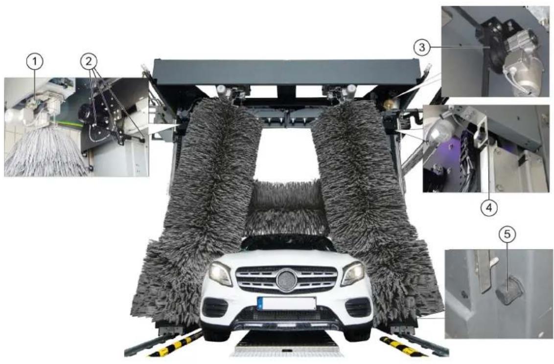
Front portal maintenance overview
① Roof brush drive belt and belt pulley
2 Maintenance unit
3Side brush tilt pressure reducer
4Side brush lock pressure reducer
(5) Wheel wash pressure reducer
(6) Vehicle position 1 light sensor
Vehicle position 2 light sensor
Wheel detection light sensor
⑨ Portal movement start limit switch
Portal movement end limit switch
Lower roof brush limit switch
(12)Pillar 1 door switch limit switch
13Upper roof brush limit switch
Rear portal maintenance overview
①Side brush steering overload switch
(2) Roof drier light sensors
③ Roof drier drive belt and belt pulley
4Upper roof drier limit switch
⑤ Lower roof drier limit switch
Hall maintenance overview
4 3
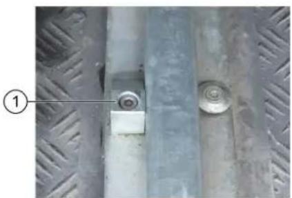
① Portal exit end position mechanical limit stop
(2)Portal entry end position mechanical limit stop
③ Fresh water dirt trap
(4) Processed water dirt trap
⑤ Hall entry and exit light sensors
Machine room maintenance overview
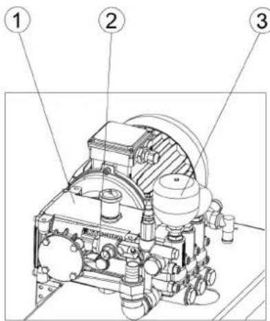
High-pressure pump
2 Oil level indicator
③ Pressure tank
④ Pressure reducer
(5) Fresh water tank
Daily maintenance plan
| Assembly Activity Performed Target | |||
| Emergency off buttonSafety switch | Check Start the washing program | am, actuate an emergency-offbutton or safety switch, the system must stop immedi-dately, then switch the system on again, see chapter "Switching on again after an emergency off". | Operator |
| Signs with operating instructions and intended use | Check the instructions for self-service customers (self-service systems only) | Check all signs for completeness and legibility.Replace any damaged signs. | Operator |
| Cleaning and care agent reservoirs | Check the filling level | Refill or replace as necessary. | Operator |
| High-pressure hoses from the high-pressure pump to the washing bay | Check Check the hoses for damage. Replace faulty hoses immediately. Danger of accident. | Operator | |
| Spray nozzles/sieves | Checking for clogging | Visual inspection (assess the spray pattern), clean if necessary. | Operator |
| Eliminate clogging Warning, do not swap over the nozzles.Unscrew nozzles individually to avoid mixing them up.Clean with compressed air or insert in a detergent solution and then clean with a brush or needle. Screw in the nozzles again. | Operator | ||
| Light sensors | Check for soiling, clean if necessary | For light soiling, wipe the light sensors with a damp cloth without detergent under light pressure. In the event of heavy soiling, spray the cloth with a gentle detergent. | Operator |
| Limits switches | Visual inspection | Check for mechanical damage and firm seating. | Operator |
| Side brushes, roof brush, wheel brushes | Check for foreign bodies | Visual inspection, remove any foreign bodies, clean dirty brushes with a high-pressure cleaner. | Operator |
| Rinsing and spray circuits | Check the water supply | In washing mode, check that sufficient water for vehicle washing is available.Too little water of no water can damage the vehicle being washed. | Operator |
| Positioning light | Function test | Interrupt the "Position 1" and "Position 2" light sensors, for the position of the light sensors see chapter "Front maintenance overview".The positioning light must display corresponding signals. | Operator |
Weekly maintenance plan or after 500 vehicle washing hours
| Assembly | Activity | Rectification | Target group |
| Roof brush rollersSide brush rollers | Visual inspection Check the tTrue running of the brush shaft.Check the brushes for tight seating.Check the brush for wear and tear.Minimum bristle length = as-new length minus 50 mmReplace the brushes if necessary. | Operator | Operator |
| Supply line hoses and pipeline Visual inspection Check for leaks | Operator | Customer Service | |
| High-pressure pump(s) Checking for leaks Check pump and line | system for leaks. Notify Cus-tomer Service if you lose oil or if there is a leak of more than 10 drops of water per minute. | Operator | |
| Checking the oil level Target level in the middle of the oil level indicator. Top up with oil if necessary (order no. 6.288-020.0) and inform Customer Service immediately. | Operator | ||
| Check pressure tank If there is increased vibration in the high-pressure pump, the pressure tank is defective. Contact Cus-tomer Service. | OperatorCustomer Service | ||
| Fresh water tank | Check the float switch | Check the function of the float valve (see "Mainte-nance work"). | Operator |
| Operating station with display | Cleaning/Care | Wipe the surface with a damp cloth, spray the cloth with a detergent and clean it if heavily soiled | Operator |
| Panel/glass front system | Cleaning | Spray the surface with an acidic cleaner and clean with a soft pad, then rinse with clean water and re-move with a squeegee | Operator |
Maintenance plan after 1000 washes
| Assembly | Activity | Performed | Target group |
| Check the running rollers of the side brush rollers | Visual inspection Check the play by moving the side brushes. Contact Customer Service in the case of excessive play between the carriage and guide. | Operator Customer Service | Operator Customer Service |
| Screws on the guide rails for the roof brush and roof drier | Re-tighten | Check for tight seating of the screws and tighten if necessary. Tightening torque 25 Nm | Operator Customer Service |
Monthly maintenance plan after 2000 washes
| Assembly | Activity | Rectification | Target group |
| Maintenance unit | Cleaning the filter | Shut off the compressed air supply and then extend and retract the wheel washing unit in manual mode until the system is depressurised. Check the pressure gauge to ensure that the system is completely depressurised. Unscrew the filter housing, remove the filter insert, clean the filter with compressed air, fit the filter, screw the cover on again. | Operator |
| Processed water and fresh water dirt trap | Cleaning | Shut off the water supply, unscrew the cover of the dirt trap, remove the filter, flush the filter with water, fit the filter again, screw on the cover. | Operator |
| Pressure reducer | Cleaning the sieve | See "Maintenance work". | Operator |
| Roof brush and roof drier | Visual inspection of the drive belts | Check the condition of the drive belts and replace if necessary. | Customer Service |
| All limit switches | Check the fasteners and clearances4 | Check the clearance between the limit switch and switching vane using a feeler gauge. If necessary, adjust the limit switches by adjusting the plastic nuts. Limit switch clearances: ·∅30 mm = 5.0 mm ·∅30 mm = 2.0 mm ·Side brush movement counter ∅12 mm = 3.0/ ±0.1 mm ·Roof brush/drier lifting counter ∅12 mm = 3.5/ ±0.1 mm | Customer Service |
| Washing hall | Cleaning | Spray the surfaces such as floor, walls and tiles with an acidic detergent, allow to take effect, clean off the detergent with a soft pad (white) | Operator |
Half-yearly maintenance plan or after 5000 washes
Annual maintenance plan or after 10000 washes
| Assembly | Activity | Rectification | Target group |
| Cables and hoses for: • Energy pillar or • energy chain or • trailing cables | Visual inspection Condition of | the hoses and cables. Check the hoses and connecting elements for leaks. | Operator |
| Side brushes, roof brush, wheel brushes | Basic cleaning Spray the brus | hes with a detergent (pre-cleaner or hall cleaner), allow to act and rinse thoroughly with high-pressure cleaner and warm water at max. 40 °C | Operator |
| Assembly | Activity | Rectification | Target group |
| Self-service gantry Check the toothed rack for wear and tear | Operator Customer Service | ||
| Wheel washing brushes Visual inspection Replace the brushes after approx. 15000 washes.Replacing the wheel washing brushes: Remove the screws inside the brush ring, remove the wheel washing brush, fit the new wheel washing brush and fasten in place with the screws. | Operator Customer Service | ||
| High-pressure unit Safety check | Carry out a safety check according to the guidelines for liquid emitters. | Expert customer service |
Maintenance work
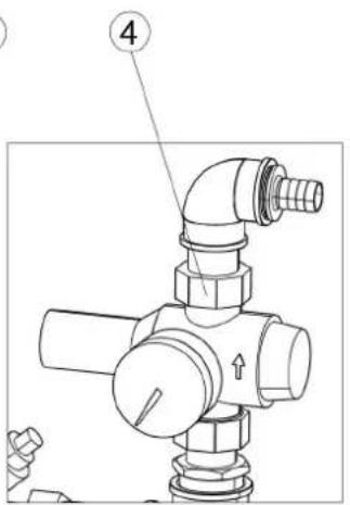
Clean the pressure reducer strainer
- Close the water inlet.
- Unscrew the cover.
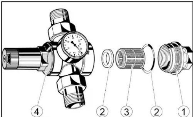
Cover
②Seal
③ sieve
(4)Pressure reducer
- Take out the strainer and rinse it with water.
- Insert the sieve into the pressure reducer. Ensure that the seals are seated properly.
- Screw in and tighten the cover.
Check the float switch
- Check whether water comes out from the overflow opening.
① Fresh water tank
Cover
③Overflow opening
4Float valve
⑤ Outlet
- Remove the fresh water tank cap.
- Check whether the float valve closes completely when the fresh water is full.
Note
When the float valve is completely closed, no water comes out of the outlet.
4. Replace the cover.
Troubleshooting guide
△WARNING
Risk of injury from machine movements
Switch the system off before performing maintenance and servicing work.
Secure the main switch with a padlock to prevent it from being switched on again.
WARNING
Risk of injury from pressurised compressed air reservoirs and lines after the system has been switched off
Depressurise the system before performing any work on the system. Check the pressure gauge at the maintenance unit to ensure that the system is depressurised.
WARNING
Risk of injury from the high-pressure system after the system has been switched off
Depressurise the high-pressure system before performing any work on the system.
Target groups for troubleshooting Who is permitted to eliminate faults?
Operator
Work labelled with "Operator" may only be performed by instructed persons who are capable of safely operating and maintaining the system.
Qualified electricians
Qualified electricians are persons with professional electrotechnical training and qualifications.
Customer Service
Work labelled with "Customer service" may only be performed by Kärcher customer service technicians or Kärcher-authorised installation technicians.
Fault messages on the display
Note
The faults, causes and remedies are shown in plain text on the display.
Critical fault
SB2 Position not logical

Endpos. In-Out Simultaneous
Check Limit Switches
Inform Technical Service
F0212 31.01.2019 14:35:29


Message 2/2

Eliminate the malfunction according to the message on the display and then acknowledge via the OK button.
Displays on the positioning light
| Display Blink | code | Cause Remedy | |
| STOP | STOP | Blink-ing alternately | Manual mode active |
| STOP | lights up | Washing is running | |
| STOP | lights up | Washing stopped | |
| STOP | STOP | Blink-ing alternately | Error active |
| STOP | STOP | Blink-ing briefly | Emergency-off active |
| STOP | STOP | lights up | Move in-to position |
| STOP | lights up | Stop positioning | |
| Display Blink | code | Cause Remedy | |
| STOP | lights up | Reverse the positioning | |
| STOP | STOP | Blinking | Washing finished |
| STOP | STOP | Blinking | Washing finished |
Faults that are not displayed
| Fault | Cause | Rectification | Person responsible |
| Inadequate cleaning efficiency | No cleaning agent or insufficient cleaning agentNo air pressure or insufficient air pressure in the supply lineWorn brushes | Check the cleaning agent filling level and refill if necessary,vent the dosing pump.Check the air pressure and adjust if nec- essary (0.6 MPa (6 bar) at the mainte- nance unit pressure gauge).Clean the cleaning agent intake filter, check the cleaning agent pipes for dam- age.Check the brushes and replace if nec- sary. | Operator |
| High-pressure pump does not reach pressure | Suction-side pipeline system leak- ing.Water shortage | Check the screw connections and hos- es Eliminate water shortage. | Operator, Customer Service |
| The pressure gauge pointer of the high-pressure pump vi- brates strongly | Pump sucking airPressure tank defective | Check suction line.Replace pressure tank. | Customer Service |
| The high-pressure pump safety valve opens | Clogged washing bay nozzles | Check, clean, replace nozzles. | Operator |
| Hose or high-pressure valves clogged | Remove clog. Customer Service | ||
| Too little water or no water coming out of the nozzles | Dirt trap cloggedInsufficient water pressureNozzle cloggedAir in the centrifugal pumpSolenoid valve or supply line clogged | Clean the dirt trapCheck the water supply pressure and pumpsClean the nozzles with compressed airVenting the centrifugal pump by loosen- ing the bleed screwCheck the solenoid valves and supply lines (water and electricity) and repair if necessary | Operator |
| Water continues coming out of the nozzles after washing | Dirty solenoid valve | Clean the solenoid valves | Customer Service |
| Inadequate drying Too little or | too much drying aidIncorrect drying aidNo air pressure or inadequate air pressure | Increase or reduce the dosageCheck the cleaning agent filling levelClean the intake filterVent the dosing pumpUse original drying aid from KärcherCheck that the drying blower is working correctly | Operator |
| The wheel washing brush does not rotate | The motor circuit breaker in the control cabinet has triggered Contact pressure too high | Check the motor circuit breaker in the control cabinetReduce the contact pressure at the wheel wash pressure reducer | Operator |
| The wheel washing brush ex- tends slowly or not at all | No air pressure or inadequate air pressure | Check the air pressure and adjust if nec- essaryIncrease the contact pressure at the wheel wash pressure reducer | Operator, Customer Service |
| The wheel washing brush ex- tends at the wrong position | Dirty light sensors | Clean the light sensors and check the settings if necessary | Operator |
| The brushes become dirty quickly | Shampoo dosage too low | Adjust the shampoo dosageCheck the water volume and adjust if necessary | Operator |
| The undercarriage wash nozzle pipes pivot too slowly/too quickly or not at all | No air pressure or inadequate air pressurePivoting unit heavily soiledChokes incorrectly adjusted | Check the air pressure in the supply lineand adjust if necessaryClean the pivoting unitRe-adjust the chokes | Operator, Customer Service |
| The system cannot be switched on | Power supply fault | Ensure a fault-free power supply as specified in the connection values | Operator, qualified electrician |
Venting the centrifugal pump
- Loosen the bleed screw.
① Centrifugal pump:
② Bleed screw
- If water comes out, screw the bleed screw in again.
Warranty
The warranty conditions issued by our relevant sales company apply in all countries. We shall remedy possible malfunctions on your appliance within the warranty period free of cost, provided that a material or manufacturing defect is the cause. In a warranty case, please contact your dealer (with the purchase receipt) or the next authorised customer service site.
(See overleaf for the address)
Technical data
| CW 3 / CW 5(CWB 3/1) | CW 3 / CW 5(CWB 3/2) | CW 3 / CW 5(CWB 3/3) | ||
| Plant dimensions | ||||
| Washing height mm 2100, 2200, 2300 2400, 2500, 2600 2700, 2800, 2900 | ||||
| Frame height mm 2900 3200 3500 | ||||
| Total height mm 2930, 3030, 3130 3230, 3330, 3430 3530, 3630, 3730 | ||||
| Frame width mm 3500 3500 3500 | ||||
| Total width of side brushes mm 4040 4040 4040 | ||||
| Total width of splash guard mm 4060 4060 4060 | ||||
| Frame depth/depth with rotating brushes | mm | 1600 / 2170 | 1600 / 2170 | 1600 / 2170 |
| Total length of short hall | mm 2070 | 2070 2070 | ||
| System width at mirror height | mm 2450 | 2450 2450 | ||
| System width in the wheel wash region | mm 2100 | 2100 2100 | ||
| Track width of guide rails | mm | 2550, 2700, 2800 | 2550, 2700, 2800 | 2550, 2700, 2800 |
| Hall width with safety clearance | mm 4500 | 4500 4500 | ||
| Washing brushes | ||||
| Side brush diameter | mm 975 | 975 | 975 | |
| Side brush rotary speed | 1/min | 107 | 107 | |
| Roof brush diameter | mm 975 | 975 | 975 | |
| Roof brush rotary speed | 1/min | 127 | 127 | |
| Portal speed | m/min | 0 - 24 | 0 - 24 | |
| Electrical connection | ||||
| Mains voltage | V | 400 | 400 | |
| Frequency | Hz | 50 | 50 | |
| Power rating | kW | 10-16 | 10-16 | |
| Controller maximum supply fuse | A | 35-50 | 35-50 | |
| Water connection | ||||
| Nominal width | Inches | 1 | 1 | |
| Flow pressure as per DIN 1988 (at 100 l/min) | MPa | 0,4 - 0,6 | 0,4 - 0,6 | |
| Max. temperature | °C | 50 | 50 | |
| Compressed air connection | ||||
| Nominal width | Inches | 1/2 | 1/2 | |
| Pressure | MPa | 0,6 - 0,8 | 0,6 - 0,8 | |
| Consumption/washing (without frost protection device, pro-gram-dependent at a vehicle length of 4.5 m) | I | 50 | 50 | |
| Consumption with without frost protection, approx. | I | 700 | 700 | |
| Determined values in acc. with EN 60335-2-79 | ||||
| Sound level, washing process with drying | dB(A) | 87 | 87 | |
| Sound level, drying mode only | dB(A) | 91 | 91 | |
| Sound level, high pressure module | dB(A) | 86 | 86 | |
| Sound power, washing process with drying | dB(A) | 101 | 101 | |
| Sound power, drying mode only | dB(A) | 105 | 105 | |
| Sound power, high-pressure module | dB(A) | 101 | 101 | |
| Uncertainty | dB(A) | 3 | 3 | |
Subject to technical modifications.
Water and detergent consumption
The water consumption depends on the vehicle length, system equipment and washing program.
The specified values are by way of example for the consumption per vehicle wash.
Note
Boundary conditions:
Vehicle length 4.5m
Declaration of Conformity
EU Declaration of Conformity
We hereby declare that the machine described below complies with the relevant basic safety and health requirements in the EU Directives, both in its basic design and construction as well as in the version placed in circulation by us. This declaration is invalidated by any changes made to the machine that are not approved by us.
Product: Washing bay
Type: 1.534-xxx
Currently applicable EU Directives
2006/42/EC (+2009/127/EC)
2014/30/EU
2009/125/EC + 2009/1781
Harmonised standards used
EN ISO 12100
EN 17281
EN 60204-1
EN 61000-6-2: 2005 + AC: 2005
EN 61000-6-4:2007 + A1:2001
The signatories act on behalf of and with the authority of the company management.

H. Jenner
Chairman of the Board of Management

S. Reiser
Manager Regulatory Affairs & Certification
Documentation supervisor:
S. Reiser
Alfred Kärcher SE & Co. KG
Alfred-Karcher-Str. 28 - 40
71364 Winnenden (Germany)
Ph.: +49 7195 14-0
Fax: +49 7195 14-2212
Winnenden, 2022/11/01
Declaration of Conformity (UK)
We hereby declare that the product described below complies with the relevant provisions of the following UK Regulations, both in its basic design and construction as well as in the version put into circulation by us. This declaration shall cease to be valid if the product is modified without our prior approval.
Product: Washing bay
Type: 1.534-xxx
Currently applicable UK Regulations
S.I. 2008/1597 (as amended)
S.I. 2016/1091 (as amended)
2009/125/EC + 2009/1781
Harmonised standards used
EN ISO 12100
EN 17281
EN 60204-1
EN 61000-6-2: 2005 + AC: 2005
EN 61000-6-4:2007 + A1:2001
The signatories act on behalf of and with the authority of the company management.

H.Jenner
Chairman of the Board of Management

S. Reiser
Director Regulatory Affairs & Certification
Documentation supervisor:
S. Reiser
Alfred Kärcher SE & Co. KG
Alfred-Karcher-Str.28-40
71364 Winnenden (Germany)
Ph.: +49 7195 14-0
Fax: +49 7195 14-2212
Winnenden, 2022/11/01
Contenu
Remarques generales 46
Pollution due aux vehicules
Fuites d'huiles.
Installation reverse-osmose
Diagnostic maintenance
2006/42/CE (+2009/127/CE)
2014/30/UE
2009/125/CE + 2009/1781
71364 Winnenden (Germany)
Tél.: +49 7195 14-0
Télécopie: +49 7195 14-2212
Winnenden, le 01/11/2022
Indices
71364 Winnenden (Germany)
Tel.: +49 7195 14-0
Fax: +49 7195 14-2212
Winnenden, 01/11/2022
Inhoud
Installatie in storing
Toets home
Langdurig stilleggen
Chairman of the Board of Management
S. Reiser
Manager Regulatory Affairs & Certification
71364 Winnenden (Germany)
Tel.: +49 7195 14-0
Fax: +49 7195 14-2212
Winnenden, 2022/11/01
Indices de Contents
Avisos generales. 118
Los dispositivos atrapadores de sociedad retienen particulas queSEOSEOSEOSEOSEOSEOSEOSEOSEOSEOSEOSEOSEOSEOSEOSEOSEOSEOSEOSEOSEOSEOSEOSEOSEOSEOSEOSEOSEOSEOSEOSEOSEOSEOSEOSEOSEOSEOSEOSEOSEOSEOSEOSEOSEOSEOSEOSEOSEOSEOSEOSEOSEOSEOSEOSEOSEOSEOSEOSEOSEOSEOSEOSEOSEOSEOSEOSEOSEOSEOSEOSEOSEOSEOSEOSEOSEOSEOSEOSEOSEOSEOSEOSEOSEOSEOSEOSEOSEOSEOSEOSEOSEOSEOSEOSEOSEOSEOSEOSEO SEO
Interruptor principal
2006/42/CE (+2009/127/CE)
2014/30/UE
2009/125/CE + 2009/1781

Chairman of the Board of Management

S. Reiser
Manager Regulatory Affairs & Certification
Responsible de documento:
S. Reiser
Alfred Karcher SE & Co. KG
Alfred-Karcher-Str.28-40
71364 Winnenden (Germany)
Tel.: +49 7195 14-0
Fax: +49 7195 14-2212
Winnenden, 01/11/2022
Indices
Indicaoes gerais. 142
Observar as dimensional
B2 = espuma, insects, Intensiv Basic
C1 = agua reciclada, champô
③ Interruptor principal, ver Interruptor principal
Interruptor principal
EL2 Interruptor final ilogico

Pos. final inter.-exter. simult.
Verificar interruptor final
EL2 Interruptor final ilogico
Pos. final inter.-exter. simult.
Verificar interruptor final
Informar Assistance Tecnica
F0212 31.01.2019 14:35:29

Mensagem 2/2


2006/42/CE (+2009/127/CE)
2014/30/UE
2009/125/CE + 2009/1781
Chairman of the Board of Management

S. Reiser
Manager Regulatory Affairs & Certification
Winnenden, 2022/11/01
Indhold
Tilkobling after nodstop
Obs
Sorg for at eliminere arsagen til aktiveringen af ndstopknappen,inden anlagget genindkobles.
2006/42/EF (+2009/127/EF)
2014/30/EU
2009/125/EF + 2009/1781

H. Jenner
Chairman of the Board of Management

S. Reiser
Manager Regulatory Affairs & Certification
71364 Winnenden (Germany)
TIf.: +49 7195 14-0
Fax: +49 7195 14-2212
Winnenden, 2022/11/01
Indhold
Generelle merknader 188
Miljøvern 188
Innmatingsfordereler
Grunnstilling (blà tast)
E5017 31.01.2019 14:24:48

Melding 2/2


Service ma utfores,
avtal tid
for service


endebryter, informer service
F0212 31.01.2019 14:35:29

Melding
2/2


2006/42/EF (+2009/127/EF)
2014/30/EU
2009/125/EF + 2009/1781
Anvendte harmoniserte standarder
EN ISO 12100
EN 17281
EN 60204-1
EN 61000-6-2: 2005 + AC: 2005
EN 61000-6-4: 2007 + A1: 2001

H. Jenner
Chairman of the Board of Management

S. Reiser
Manager Regulatory Affairs & Certification
71364 Winnenden (Germany)
TIf.: +49 7195 14-0
Winnenden, 2022/11/01
Innehalle
Allman information 210
Miljöskydd 210
Forsprutting (losa spp. insecter)
Dags for underhall, boka underhallstid


H. Jenner
Chairman of the Board of Management

S. Reiser
Manager Regulatory Affairs & Certification
Dokumentationsbefullmaktigad:
S. Reiser
Alfred Kärcher SE & Co. KG
Alfred-Karcher-Str.28-40
D-71364 Winnenden (Germany)
Tfn: +49 7195 14-0
Fax: +49 7195 14-2212
Winnenden, 01.11.2022
Sisälto
Yleisiä ohjeita 232

H. Jenner
Chairman of the Board of Management

S. Reiser
Manager Regulatory Affairs & Certification
71364 Winnenden (Germany)
Puh.: +49 7195 14-0
Chairman of the Board of Management

S. Reiser
Manager Regulatory Affairs & Certification
YTEUVOUC TEXVIKOU QAKeAU:
S. Reiser
Alfred Karcher SE & Co. KG
Alfred-Karcher-Str.28-40
71364 Winnenden (Germany)
Tnλ: +49 7195 14-0
Φaξ: +49 7195 14-2212
Winnenden, 2022/11/01
CopepxaHne
O6uyeka3aHn 279
3aunTaOkpykaHoueI cpebl 279
Yka3aHnnoTexnke6e3oNaChOCTn 279
IcnoB3oBaHne no Ha3HaueHIO 281
PoiB0D BOIbI 282
PpHnAdIeXHoCTn 3aNaChbIe YacTn 282
OncanHe MoeHOn ycTaHOBKn 283
3JemeHbI ynpabJeHn 287
Onncnne nncnnner 288
BvO B 3Kcnpnyatauio 291
291
BbIOd n3 3KcNpyatau.. 293
YxOuI TexHnueckoe o6cIyKbHaHne 294
IOMOuB npH HeNCnpaBHOCTx 300
Tapaantna 303
Texnueckx xapaKTepeNtukn 303
DeknapaunO COOTBETCTBn CTanapTAM EC 304
06uyeyka3aHn
IpeepnepBbIM npImeHHeM ycTpoiCTBa
O3HaKOMITbCc DaHHoOpuHnHaJIbHOu HNCTpyKUnei
no 3KcnIyatauHn IraB0 O TexHnke 6e3oNaCHocTn.
ДeнCTBOBaTb B COOTBETCTBn C HmN.
CoxpaHbIbIaIbHeIeero IOnb3OBAHn nnIIN
cneyuoueroBnaedbua.
pepepa6oTkn, n3aacTyO TaKne KOMnHOHeHTbl, KaK 6aTapeN,
akymyTOpblnnMaCNo, KOtOpBie pN HePpaBnBbHOM
06paueHnn Hn HnHaJnEkaaey yTnIn3aun npedctabna
NOTEHuaJIbHyIO npaHocTb DnIy 3dOpOBBy I OkpyKaIOUeI
cpebl.Tem He Mehee,daHHbIe KOMNoHEnTbI HeoXoDmbl dnn
npabunbHn pa60tby yctpoNCTBa. YcTPOINCTBa, 0603Haeh
3TMM CnMBOJOM, 3aIpeueHO yTHIN3NpuOBaTB BmecTe C
6bITOBBIMNOTXODAMN.
Yka3aHnno KOMnHOHeTAM (REACH)
Pn HnpabNbHOM ynpaBHeHn nnncNoB3OBaHn He no
Ha3NaueHnIO OtnepaTOpU INpym IIOJMy YrpoXaet ONaCHOCTb
IIO pniuHHe:
BbICOKOTo DaBnHeHn B0Dbl;
BbICOKOTo 3JIeKTPnueckoTo HAnpJKeHn;
C XaTOrO BO3DyXa;
MOIOxCpeDCTB.
Bo n36eXaHHe onaCHoCTeI JIODei, XINBOTbIX INMByeCTBa
IpeepnepBbIM NcIOnb3ObaHneM yCTaHOBKn O3HaKOMTbC A:
HCTpyKneI NO 3KnJyatauIN, BKNIOUaB BCE yKa3aHnA NO TEXHNKe 6eOtonachOCTN;
COOTBETCTBYUIMN HauNoHaJIbHbIMN 3aKHOJaTeIbHbIMN HOPMAMN
yka3aHnMn n ToTexnke 6eOnaCHOCTN, KOTOpbIMn
COPPOBOXKaIOCTCAHcNtB3yEmbIe MOUcne CpeIcTBA.
Y6eHNTbCBA TOM,HTO:
BbICAMNIOHARINBCEyKa3aHnI;
BCE NOJIb3OBaTeJN yCTaHOBKn npOHΦOpmuPoBaHbI 6 3TNX
yka3aHnX INoHJINx.
Bce nua, mHeoune OTHoueHne K yCTaHOBKe, BBOy B
3KcnnyatauioynpaBHeHHo,DOnxHbI:
IMMETCOOTBETCTBYUOYKBAHINKauNIO;
3HaTbN CO6nIOdaTb INHCTpyKuHIO NO 9cKnIyatau;
3HaTbN CO6HNOaTaB COOTBeTCTByOuue IpapBnna.
ObecneHtB,TO6bIBpeKIMe camOo6cnyKuBaHnBCE
IOJIb3OBaTeIN 6blJIN PPOINHΦoPMnPoBaHbI C NOMOJIbU OHTKIX
yka3aTeNbHbIX Ta6nueKo:
BO3MOXHbIXOnaCHOCTAX;
yctpoiCTbax630naCHOCTn;
- ynpabJIeHn yCTaHOBkoN.
HCTpyKuIN NO 3KcNpyataaUN DOJXHBbBbINONHrTbcR
ONEpaTOPOM MOeHON yCTaHOBKN B COOTBETCTBNN C MEcTHbIMN
KaDpOBbIMN yCIOBnMn BpyKOBOdCTBe NIO 3KcPiNyTaUIM.
PykoOBOCTBO NO 3KcNpyataunn DoJnxHo Jekatb npd pykoi
onepaTopa N6o 6bItb BbIbeSeHO B pa6oye 3OHe.
CTeneHb onaCHOctN
ONACHOCTb
- Yka3aHue omHocumelbHO HenOpecmEeHHo ap03aue
onachocmu, komopar npueodum K mxejblm mpaemam unu K Cmepmu.
△NPEyPEXKDEHNE
- Yka3aHue omHocumelbHo 603MOxHOJ NOMEHuaJIbHO
Onachou cumyaauu, Komopar MOKem npueecmu K mxejblm
mpa6MaM UUNK Cmepmu.
△OCTOPOXHO
- Yka3aHue Ha nomeHuuaIbHo OnachHy cumyaquio, Komopar
MOXEM npueecmu K nonyeHuO neaKux mpaem.
BHIMAHHE
- Yka3aHue omHocumelbHO 603MOXHOJ nomEHuaIbHO
onachou cumyaauu, komopar moxem noeneyh 3a cobou
MamepuaHbHuyeep6.
PpeDncaHnI NnpeKtnBbl
Дяэксл�аТиДаннйуCTAHOBKNВФepepaTINBHOI
Pecny6nke TepmaHn npimHeIOTc cIeMyOuHn HOpMbI
DnpeKtNBbl (noTyuHTb KOToPbIe MoXHO no aDpcy CarI
Uym,NCXOJaIOnOT yCTaHOBKn,630NaCEH DnKJNeHTOB aBTOMoIKN 3-3a KpaTkoBPemEHORO BO3neCTBnR.
PpumeyHue
YpOBeHb Wyma Ha 8be3e npu paBome cywunku cocmaenrEm 91 B(A)
△NPEUYPEXKDEHNE
IoepekehdeHue cnyxa o6cnykueaoue2o nepcohana e0 epema pa6omby cyuunku
NcnoB306amb npomueowmble HayuHuku 8o epempaobcyuunku.
Ioepekehue opaHOe cnyxa u3-3a cuJbHO2O wyma e MauHHOM omdehenu
Hadeeamb nodxoduue cpecdmea 3auumbI opzao8 cnyxahaxo8cb mauunHom omdehenuu.
Onachoctn, BblbBaemble 3neKtpueecknH anpaeKeHHem
ONACHOCTb
Onachocmb ydapa 3neKmpuueckum mOKOM
Huko2da He mpozamb 3neKmpuueckue KOMnOHeHmbu npoeoda enaxhbuMPykamu.
Obecneumb 3auumy 3eKmpuueckux coedunhumebhix npoeodoo unu ydnunemene om noepexdehu, hae3da, pa3daanueaunur, paarmzueaunur u np.
3aunamb kabenu om 0o3eucmeu bfcokux memnepamyp, Macna unu noepexdehura ocmpbuMu kpaMu.
Huko2da He HanpaBnMb cmpy0 60dbHa 3neKmpueeckue npubopblu obopydoaHue.
Obecneumb 3auumy eex mokoeedyux demaneu b paobeu obnacmu om cmpyu 60bl.
UcmaHOeKy nOcknouamb monbKO K 3a3emJIeHHbIM HaJIeXaUm o6pa3OM ucmOHukam moka.
Bce paobmbc 3nekmpuueckmu yacmmu ycmahoku npuyamb bblonnmy monbco cneuaanucmy-3nekmpky.
OnachbIe dIy 3dOpOBb BeueCTBa
ONACHOCTb
OnachbIe 3doepoobba eueecmea
Osbamb npuaaembe, paeeamaHHbpekomeHdaauu no yumrmy cpedmey.
Huko2da He numb eody u3 ycmaHO6Ku! OHa He reIaemr numbeoeu u3-3a do6aeneHua Ycmaueo cpeOmea.
Ecnn 3knnnyamau ycmahoeku npumehemc ooueHHa mexhueckara boda, mo doJxnbI bblonHmcbr npednucHur npou3oodumena ycmahoeku bodonodaomoeku no npedomepauehuo poema MukpoojaHu3Mo6.
He donyckamb nonadahure b Moeyu ycmahoeky eueecme, komopbie aenomc HecmaHdapmhbIMU dna obyHou eheun He ouucmku mpancnopmhbx cpecmbe (hanpumep, mxekblte Memannbl, necuudbl, paduoakmuene bie eueecmea, fekanuu unu unfucupobaa Hne Mamepuanbl).
OnachocbBpe3yNbTaTe c6oNtAHn
HeKoHTpOJIpyeMbI Nepe3anyck yctaHOBKn nocne c608 nITaHnN NCKIIOHaTc KOHCTpyKTNBbIMM MepaMn.
OnachocbOkpykaohuei cpeoTc0hBix BOI
Co6nIOaTb MeCTHbIe npabINa No yTNIN3aUNC cTOUHBx BOJ.
Copepkanhe BncnpaBHOCTn Ha3Op
IЯ obecneueHna 6e0nacHO paObTy yCTaHOBKn I npedOTBpaUeHn OAnChOCTeN BO BpeM TeXHmYeCKoR O6cnyKINBaHn, HAd3opa N IcNbTaHn Heo6xOdIMo Co6nIOdaTb COOTBeTCTByUOUIne IHCTpyKUn.
Texnueckoe obcnykBaHne n coepkaHne BncpabHOCTN
Pa60tI no TEXHnueckOMy 06cnyKnBaHHIO n CopeKxAHNO B nCnpaBnOCTN DoJHKbI NPOBOuNTbcS CneuaJIACTOM uepe3 peYJrApHbIe NpOMExkyTKBpeMeHN CoRNaCHO yKa3aHnM npOn3BoUnteN. Co6NJaTa DeiCTByUoJe npAunla n Tpe6oBAHnK 6Be3oNaChOCtN.DoBepaTe pa60tI c 3NeKtpnueckOy YcTaHOBKO ToJbKO KBaINΦnCuPObaHHbIM 3NeKtpnKAM.
△NPEDYNPPEKDEHNE
OnachocmbmpaMupoeaHuaU3-3a 6paauouuxcyaacmeu Maunhbl
BbiklHouamb MoeHyu ycmaHOky neped npoBeDeHuem pa6om no mexHuueckomy ocbIyXueaHuU u codepxaHuU e ucnpaBHoMu.
3aummb 2naeHbI nepeKIOyamEnb om noemopHOO 6KnOHeHua, Hapumep, c NOMoUbIO BUCyEeO 3Amka.
△PENDEUYNPEKDEHNE
OnachocmbmpaMupoeaHua3-3a ebinycka cKamoo0 0e3dyxa u3 bannohu u coedunehu, haxodauuxcno daeJeHuem nocne ebiknouehu ycmaHo6ku
Cnyckamb daeneHue neped npoeedeHuem IIObix pa6om Ha ycmaHOeke.
Ppoeepm b omycmeue daeneHua Ha MaHomempe nHe6MO6nka.
△NPEDYNPEXDEHNE
OnachocmbmpaemupoeaHua3-3a binycka cKamoo 0o3dyxa u3 cucmemblc xamblm oo3dyxom, haxodaeuecn pod daBHeuem nocne bikluoyehur ycmahOBku
Ipepe bblnoJIHeHue mIObIx paobm c ycmaHOaKoCnyckamb daeneHue e cueme Me bICOKOz daeneHue.
Had3op
Ipeep nepbim IcnoIb3ObaHnem DaHHa MoeHna yCTaHOBka DIOJXHa 6bITb IpOBepHa KBaIINΦuIpOBAHHbIM CNEuaJIInCTOM Ha IcnpabHocTb, Nocne 3TOO OHa TaKke DOJXHa IpOBeprTc, IO KpaHHe Mepe, KaXdIbe WeCtB MeCraUeB.
3ta npOBepKa BkHouaET B c6e npexde BCero:
Bn3yaJIbHbI OCMOT Ha IpeDMET BUNIMOTO N3HOCA NIN NOBpeKDeHnA;
- npOBepky fYHKUHOHPOBaHnra;
- EKeHbHy npOBepky ueoCTHOCTn npabOTocO6HOCTn 3aunTHoro obopyoBaHn yCTaHOBOK camoo6cnykHBaHn nepeHaayanom ekcnnyatau, a taKe npn Heo6xOIMOCt npOBepky ycTaHOBOK (He pexke Ondoro pa3a B Meca).
IcnoB3OBAbOpHnHaJIbHbIe DeTANI
IcnoIb3OBAt ToIbKO opuHnHaIbHbIe DeTaII ON I3rTOBHTeJI
IIIN peKOMeHNDoBaHHbIe IM DeTAlN, B IpOTNBOM Cnyae
raPANTIHbIe PpeTeH3nn 6yDyT aHHynIpOBaHbl.
CobnDabB BCE nHCTpykunno TeXnke 630naCHOCTN KcNpyataun, npunaeraMble K 3Tm DeTaIaM.
3TO OTHOCITK:
3anachbIM N 6bICTPOU3HaUNBaIOUMCJ DeTaIaM;
KOMnEeKToHmM DeTaIaM;
-экплуataционныМatepenanm;
MOHUM CpeDCTBaM.
PpeoxpahnteBhieyctpoiCTBa
Hacocb BbICOKO DaBnEHH, NtAIOUe yCTPOIcTB OIN MOKIN DnHua m MoKy BbICOKO DaBnEHN, IMeIOT CNeDyIOUne 3aunTHbIe yCTPOIcTBa.
PpeOxpaHnTeJbHbI KnanaH
PpeOxApaHnteBnKnaanOTKpbBaetc npn ppeBbIeHNn DOnyCTmOro pa6oery n36bItoHoro daBneHn, n Boda BBtKeaET HApKy 6e3 daBneHn.
IcnoNb3OBAHHe no Ha3HaueHnIO
3TaMoeyHae yCTaHOBka npedHa3HaueHa NCKIIOHTeBHO nBHeUHeOncTKeIeKOBbIX aBTOMo6nEi CO cTAHdApTHoN KOMJIeKtaUneu 3aKpbITbIX aTOfoyproHOB.
IcnoJIb3ObaHne no Ha3HaueHHo TaKke BKnIOyAeB Ce6a:
- co6nIOeHHe Bcex yKa3aHnB DaHHo INHCTpyKuIN NO 3KcNlyatau;
- co6bIIODeHHe INCTpyKcIM N O OCMOTpy IN TexHnueCKOMy 06cIpyKINBAHNIO.
BHIMAHNE
Onachocmb noepkdeHua mpaHcnopmhbix cpecm npu uonlb3oehuu emok CareTouch
Obopyoabmycmaohky MohmaxHbIM KOMnneKmOM
eBCOKO2 daNeHua UUN npedapumEnbHO NOMbM
mpaHcnopmHoe cpecm8o, eCnu nHaHupyemc uCnOB30eAHue
uemok CareTouch.
Co6nIeHne pa3MepoB
Bo n36ekaHHe NOBpeKdEHH TpaHCnOpTHbIX CpeCDTB MoechOnyCTaHOBKN MOXHO YNCNTb TOJbKO JIEKOBbIe ABTOMObIMN 3akpbTbe ATOOpyroHbIB COOTBeTCTBm C yKa3aHHbIMN npedeJIbHbIMn pa3MepaMn, CM. rnaBy TexHuueckue xapakmepucmku.
PnOaBOD BoAbI
Дязцьспспспспспспспспспспспспспспспспспспспспспспспспспспспспспспспспспспспспспспспспспспспспспспспспспспс. yctahOBKOn n CetbO NITbEBO BO OTOCHa6xHcNn DOJXHa 6bTb yctahOBJIeHa pa3B83Ka OT CETn KaterOpm5 corIacHO EN 1717.
MOHTAX
MOHTAX yCTaHOBKN DONIXEN PNOBOIDNT KBaINΦNUPOBAHHBI nepcoHAn. Pn MOHTAXe CO6NIoDAb MEcTHbIE DEiCCTBYIOUne npabUNa no TEXHNke 6e3ONaCHOCTN (HaNPIMep, pacCTOHRHe MEXyD yCTaHOBKO IN 3daHInEM).
YmbiHHeHoe HnpeBaBnBHOe npImeHeHne
JIIOBOe He COOTBeTCTBvUoUee Ha3HaueHnIO pImuMeHHe 3aIpeuEHO.
OcnykBaUcHnepcoHaN HeCETOTBeTCTBHeHOCtB 3a onaCHOCTN,BO3HNKUHNE Bpe3yJIbTaTe HEnpaBnIbHO rncNoB3OBaHn. IcNoB3OBaHnE yCTpOJCTBa B Dpynx CeJx, OTNNHbIX OT ONNCaHHbIX B DaHHo JOKymeHTaUH,3anpeuHo.
BHIMAHHE
IoepekehdeHue mpaHcnopmhbix cpedcme u ycmaHOku 3a HecobnOeHua npedeBbix pa3Mepo8
mpaHcnopmno cpecmea
Cobliodambyka3aHHbIe npedeJIbHbIe pa3MepblmpaHcnpmHOzo cpeOmea,cm.ana6y TexHuueckuexapakmepucmuku.
IopTaJIbHaMaMoeHnA yCTaHOBKa He NOxOuT dJa OUcNTK:
CneuNbHbIX TpaHCnOpTHbIX CpeDCTB, HAnpMep, TpaHCnOpTHbIX CpeDCTB C HaDCTPOKAMN (HINI INIa CHa) INI KpbIWei, BbICTyNaIOUIMn HaJIo6OBbIM INI 3aHNIM CTeklOM;
CTPOINTeIbHOnTeXHnK;
- ABTOMO6nJIeNc npuIeNam;
- DByxKoneChbIX IN TpexKoneChbIX TpaHCnOpTHbIX CpeDCTB;
- ABTOMO6HJIeI CO CnapeHHbIMU WIHAMN/DBOINHbIMN UINHAMN;
- INKANOB (BO3MOXHO B KaueCTBe ONUIN)
KaBpNOJIeTOB COTKpbITbIM BepXOM;
Ka6pnoIeTOB C 3aKpbItbIM BepXOM, He IMMeIOUx 3aBepeHnnpoN3BOIDTeJr O rOHOCTM MOUeY cTaHOBKn.
Ecn 3n HcTpyKuH He coBnOaHTc, npOn3BOmTeNb MOeHbIX yCTaHOBOK He HecET OTBeTCTBeHHoCTN 3a IocneDCTBn, TaKe KaK:
Bp enpuHneHHb nepcoHaNy,
- MATEpnaJIbHbIyUyep6,
TpaBmbl KMBOTbIX.
HenpiroDhbie YnctTae CpeAdTba
BHIMAHHE
NoBbWeHHa onachocmb Koppo3uu ecJeDcmeue npumHeHn HenoDxOraeoo Yucmaeoo cpedcmea
3anpeaemc oobapomka ycmahoaku cneyioumu yucmaum cpecmamu:
- YnCTaIe e CpeIcTBO, IpeHa3HaueHHe OJIa OHnCTKINOMeUeHn MOKn.
- YnCTaIe e CpeIcTBo, IpeHa3HaueHHe OJIa OHnCTKMOUoIe yCTaHOBKn ChapyKn.
-
ChTaee cpeCTBO Ha OCHOBe KNCOTbl.
-
Ynctraee cpeCTBO, KOtOpoe HaHocntc Ht TaHcnopTHoe cpeCTBO npi NOMOUI CNEUaIbHoro annapata (HaNPmep, cpeCTBa dnn YnCTKIN KONEChbIX DNCKOB).
CpeDCTBO DnIg O6pa6OToKn CTOHbIX BOJ.
PpHaIeXHocTn 3aIacHbIe YacTn
NcnoB3OBaTbToIbKOOpnHnHaNbHbIe npnHaJNeXHOCTn 3anaChbIe yactn.ToIbKOOnrapaHTnpyOT6eOanacHyIO 6ecnepeBoHypo paboty yctpOCTBa.
Длп получени Инфорmaци O пинадлесхостя X 3ачacстс CM. www.kaercher.com.
OnncaHne MoeUHOyycTaHOBKn
06nBmOeHOnyCTaHOBKnCoCTOpOBbBbe3da
①KoJIOHHa1
②ΦopcyHKnДIЯ CmaUHbAHnI ΜeTOK (Kpyr A1/A2/A3 OIIIOHOJIbHO BmecTo C3)
(3)BepxHЯ ΚεΤκa
4KoJIOHnHa 2
(5) KnanaHbI BbICOKO IaBnHeHn
(6)Пневматуеский 6лOK Кларанов
7D03npyuOuNe HaocsbI
(8)THEBMO6JIOK
9PeDyKTop DaBJIeHnIa
10 MoIooee cpeCTBO n cpeCTBa nnyxOda
①XoOoBaYaCTb
⑫ФорсунCчToBBOO,XIMnueckmOCyWnteEm, BOCKOM (KpyrA1)
⑬ΦopcyHKnДЯHaHeceHnIeHbHaDnCKn/ npedBaPnteHbHOYBnaXHeHnI DnCKOB
(4) Annapat Дячстк Колес
15ΦOpcyHKn BbICOKOrO DaBJIeHnIaNcTKn KOJec/KoJecHOHNI
⑥ Φόpсύнк Дяг CMыBa Naеиь, удаленя Hacekombix,бa3OBа nHTeHcNBHaOчNTka (kpyr B2)
⑦ΦoPcYHKn C TexHnueeCKO BDoO, WAmpyHem (KpyrB1)
ΦOpCyHKn BbICOKOraabneHn
(9)Koner
20 OTo6paKeHHe cTaDN MoiKn
CBeToOp DvJxKeHn
06nBmOeHOn yCTaHOBKn Co cTOPOhbl BbIe3da
①БOKOBbieUeTkn2
(2)BepxHЯ Lietka
③Понровочьефорсунк(КргС3)
④ ΦopcyHKn C qHCTO BODo, XmMueeCKnM OcyuHTenEM, BOCKOM (Kpyr C2)
(5)ΦopcyHKn C TexHHuecko BDoI, WamnyHem (kpyr C1)
BepxHn BeHTnTOpHbI DnBaTeInb
(7)Дигагель Врашени 60koьых utetok2
BepxHra cyuNlka
⑨Дигателыршенибokobых utetok1
10 BoKOBbIe 1
CTaHdapTHa KOMnEKeTaIgA
Bokobblie 1eTkn
Bpaauouece60koBbIe 8ETKn OuHuaOT TpaHCnoptHOe CpeCTBO NO 60kam, Cpepen n c3a.
BepxHra 1eTka
Bpaauoaaer Bepxna Ounaaet OT rpa3n BepxHIO Uactb TpaHCnopTHoro CpeDCTBa.
Annapat nnynckkoilec (Tapebataa tke)
TtataeHbOuNCTKINDCOKOBMOeHnaYcTaHOBka OchaueHaDbMyAnnapaTamINdyaNCTKNONEc.IoXeHne KoneonpeenepetcafoaaneKTPnueeckmNaTHKOM
BpaaHouueeCaTKeN PnKMaHOCTc K DnCKAM nHeBMaTuYeckMm UHHdpam.
CmaHbAHne 1eTOK OcyIeCTBIIeTcYpe3 fOpCyHOK, pacnoJoxHHoB UeHTpe.
PpumueaHue
Peaynupyembl no ebicome annapam dnyucmku konec docmyen e kaecmee dononHeHua.
OpcyHKn npacnbIINTeJIbHbIe apKn
Texnuecka u nctara Boda paCnbIraIOCTc Ha TpaHCnOpTHoe CpeCDTO C NOMOuBIO fOpCyHOK paCnbIINTeNbHbIX Dyr.
B 3aBcMocTn OT nporpaMMb MoKn, B0a CMeuNbBaETcC MoIOUIMN CpeCTBaAMn n CpeCTBaAMn dIyXoJa.
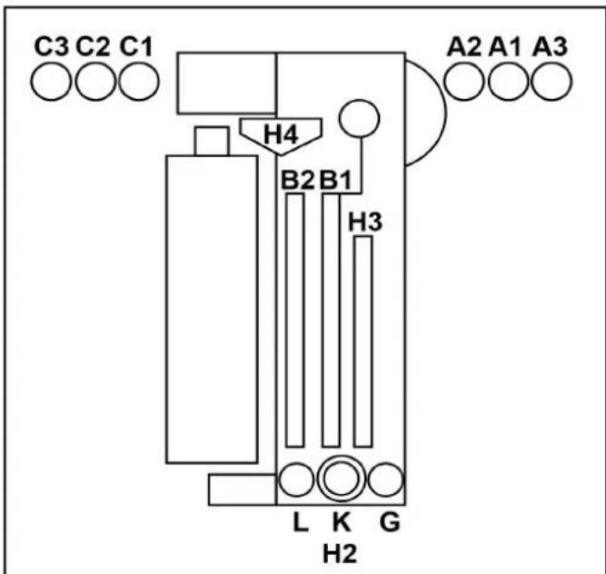
A1 = YnCTaB BODa, XmMnuecka cyuKa (XC), BocK
A2 = texHuecka B0da, WAMnHyb
A3 = nOIIPOBka (OπιΟHAJIbHO BmecTo C3)
B1 = texnuecka B0da, wamnyh
B2 = neha, ydaeneHne HaceKOMbIX, 6a3OBa INTeHCNBaOuCTKa
C1 = texHnuecka BOda, Wamnyh
C2=YnCTaB0da,XC,BOck
C3 = nolnpobka
G = npedBapntenbHoe yBnaJxHeHne DnCKOB
L=OuHCTHTeJIbCMONJIb
K=6neckHH
H2=YnCTka KOJIeC NOIbBbICOKIM DaBJIeHNEM
H3=6okobbléΦopcyHKn BbICOKOr DaBneHn
H4 = BepxHne φopcyHKn BbICOKOДaBJIeHn
Mouka c neHoi
MoIoune cpeCTBa nIpyeBapuTebHOn ONUCTKnpmehreTc Iy yBeIyuHeHn BpemEH DeNCTBn neHbl.
Bpb3ROBNK
Bpb3ROBNK 3aepxNBAHOT YacNTu, KOtOpbIe MOryT 3acOpntb φopcyHKn.
D03npyuüne hacocbI
I03nyuue HACOCbI IO6aBnIOT MOUuue CpeCTBa n CpeCTBa IyOxA B BOy.
Bokobbie fopcyhcuwn
Bo3dyx, Heo6xoDmbl dny cyk60koBbIX acTei TpaHcnpTHorO cpeCTBa, BixOaNT n3 fOpcyHOK cyuNkn.
Bepxny cywnka
BaJIKN BeHTnIaTOPa CyuINKn HAnpaBnaTcno KOnTyp TaHcNOpTHOro CpeCTBa.BcTpOeHHbIe BeHTnIaTOPb Co3dAOT notOK Bo3dyxa, Heo6xOaMbI dIpy CyuKn TpaHCnOpTHoro cpeCTBa.
CBeToΦop DBnXeHn
CBeToOp DnIXeHnI Meet CneDyUOuNcE yHKnI:
- pacnoIIOXeHne TpaHCnOpTHOro CpeIcTbA Do MOiKn;
- OTo6paXeHHe KOMaHdbI BbIe3da IocJe 3aBepWeHn MoKn;
- OTo6paXeHne HEnCnpaBHOCTei.
Φotopene
Φotopene pernctpnpuyt cneyouee:
- NOJIOXeHne I KOHTpybI TpaHCnOpTHOro CpeIcTBA;
- NOLOXeHHe KOJec TpaHCnOpTHOro cpeIcTBA.
Moouee cpeCTBO n cpeCTBa dny yxoDa
Bakc mMOUIMM cpeCTBaMn n cpeCTBaMn dnyxOa, a TAKKe DO3NpyUOuNe HAcOsbl paCNOJoxHe b K0IOnHne 2.
B KONOHHe 2 MOXHO pa3MeCTnTb MaKcMym 8 6aKOB.
Ecn Tpe6yeTc6 60bnse 6aKOB,TO MOKHO OcyueCTBtB JINHIO CHabXeHHNn3TexHnueckoKOMHaTbI.
Bcacsbaoune 7aHaHn, 6aKn n Cbra3aHHbIe c HmN Do3npyUOne Hacocbl O603HaHebl OvHaKOBbIMn CBetamn O603HaHeHue do3upykuux Hacoco8.
| Назван е | Обозсан е | Расхов | № ду зakаэ |
| RM 896 | Vehicle Pro Klear! RIM* | 15-25 мп | 6.296-077.0 |
| RM 890 | Vehicle Pro Klear! Prewash* | 10-14 мп | 6.296-003.0 |
| RM 891 | Vehicle Pro Klear! Brush* 7- | 10 мп 6.29 | 5-995.0 |
| RM 892 | Vehicle Pro Klear! Foam* | 8-10 мп | 6.295-998.0 |
| RM 893 | Vehicle Pro Klear! Dry* | 8-12 мп | 6.296-001.0 |
| RM 894 | Vehicle Pro Klear! Glow* | 10-15 мп | 6.295-993.0 |
| RM 837 | Vehicle Pro Klear! Plus** | 15 мп | 6.295-779.0 |
*Obem tapb1 10 n
**Obem tapb20n
3aBODCKa Ta6JIuYka
Ha 3aBoIckoTabnUKe yKa3aHbI BaXHbI DaHHbI o6 yCTaHOBKe.
UkaynpaBneHn
Ukaq ynpaBHeHn yCTaHOBko paCNOJoxeHa pacnPepEnIteJe nTaHn.
Pacnpedentenb nTaHn
IaBbMy BbKIOUaTeYb yCTaHOBKn YcTaHOBnEH HapacnpedeNITeJe NtAHy.
PacnpdeIeNTeJIb IITaHINpaCnOIOKeH 3a npedeNAMM MoeHOnyCTaHOBKn B TEXHueCKo KOMHaTe NII B DpyROM NOxOJaIeMe MeCe TB6JIn3N MoeHOn yCTaHOBKn.
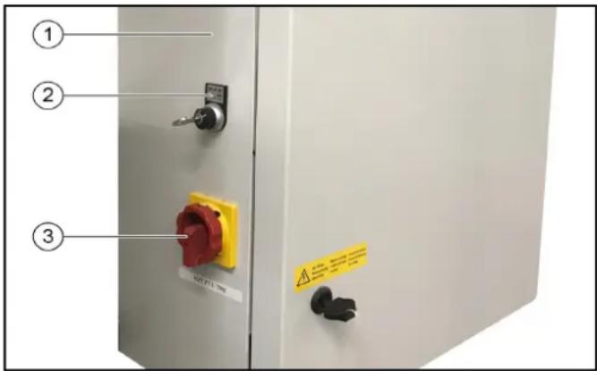
①PacnpedeNITEnb nHTaHn
(2) Kliouy-BbiklnoyateJIb, CM. Cucmema cuucneHua ABS
-0 = BbIKJIOUHTb yCTaHOBky
-1=obcnykBaHneYepe3CHTbIbATEnbMOeHONKapTbI
-2=06cIyKbAHHeYepe3CHTbIBaTeBMOeHOnKaPTbIN paHeJIynpabHEnHn(3kpan)
③「IaBHyIbIKHIOyateNb,CM.IaBHyIbIKHIOyameNb
AbapnHoe ocTaHOBka
B cnyae yrpo3bl IIOJAM, IMyIeCTBy N KINBOTbIM, YCTaHOBA Ka DOJIKHs 6bITb HEmEJNeHNO BbIKIOUeHa HaKaTnEM KHONK «ABAPINHAR OCTAHOBKA».
KhoNka «ABAPINHAR OCTAHOBKA» haoDntca:
Ha CHTbIbATEne KapT/KoIOB;
Ha nahen ynpabJeHnra;
- ONUHOHaIbHo IPN BXOe B MOeHHe NOMEueHHe, eCN HET NaHEn ynpaBHeHn JN CHTbBaTeTn KApT/KoOB.
IyHKt ynpaBHeHH
Moeuha yctaHObKa noCTabJIeTcB KOMIIeKTe C:
- NaHeJIbIy yIpaBJIeHnIc 3KpaHOM;
CHTbIBaTeIeM KapT/KoIOB (ONU).
3aunTa OT onpOKnDbIbAHNA
Mexahueckoe 3aunTHoe yctpoCTBO ydepKnaet yctahOBky Ha paobounx pebcax TaKe npn HeBepHom o6paueHm CO CTOpOHbI KIneHTOB MOKn.
DononHHTeJbHo
CuntbIbATEnbkapT/KoIOB
CHTbIbATEnb KAPr/KoIOB NcNoJIb3yETcJdNcAMOO6cnyKINBaHnMoEHHOYCTaHOBKn.
PpumeyaHue
Kapmbi/kodbi,Heo6xodumble dny o6cnykueaHua, 3anpoapammuopoaahbDncoombeemcmeyiouey cmaHOBU.
TnKluoyHe texHuecko BOdbI
IIOKJIIOUeHHeTexHnueckO BODbl NO3BOJAE NcNoJIb3OBaTb DOxJEByIO HIN OboOpTHyIO BDOy B KaueCTBe YaCTNUHO 3aMeHbI YNCTOIBoDbI.
PnaHetapbI annapaT dIy nCTKoNEc
BmecTo tapenouHoi 电TnPiHaHeapHybI annapaT dny uNCTKu TETOK OCHAUeH 3 电TkAMN.
Perynpemybno BBicote annapat dny nctkn konec
AnnapaTbI DnA YNCTK INOec TaIOKe MOrY 6bITb OCHaUeHbI peYINPOBKO BICOTbl.
UncTka KOJIeCHbIX HnW
BoaHbIe cTpyn n3 2doonHHTeNbHbIX fOpcyHOK Ha KaXdOM annapaTe IJN CNTKN KOLEC OUYUOT KONECHbIE HUN N NOPOR TpaHCnOPTHO rO cpeCTBa.
06opydoBaHne dIa OuNCTKn DnHua
C NOMOUsIO OOBpyoDBaHnI DnI OUYCTKn DNHnIa MOxHO NOMbITb HNKHIOUacTb TpaHCNOPTHO CpeCTBa. IINr 3TOr BOda paCnblIeTcR NOB BbICOKMn DaBHeHnEM n3 DByX IOBOPaHuBAIOuNXcFOpCyHOK Ha BCIO HNKHIOU AcTb TpaHCNOPTHO CpeCTBa.
PpeBapnteIbHoe paCnblHeHne (ydaJIeHHe HaceKombix)
ΦopcynKn npedBapnteHbOro paCnblneHnaHoCt NeHy NapeepdHIOU qAcTb TpaHCnpTHorO cpeCTBa. IeHa o6pa3yeTcN 13 BOdbI, CpeDCTBa dJa npedBapnteHbHoi 6pa6OTKn cKaToro BO3dyxa.
Ba3OBa HHTeHCBHbOuNTKa
IV3 cTaIOHOAPbIX φOpcyHOK Ha TpaHCnOpTHOE CpeIcTBO HAHOCTC XIMMueckn pactBop IJRA ppeDvapuTeJIbHOJ OYNCTKI.
IeHa 6bpa3yETcN 3 BOiB, CpeDCTBa IJn IpeDbapntelbHOI 6bpa6OTKn n CkatoT O3dyxa.
HaHeceHne neHbHa dNcKn
C nOMOsbIO 2-X cTaUHOHApHbIX fOpcyHOK IaIneHbHa dNcKn paCnblJrETcR BOHO-MoUOua Cmecb, BCNEHeHHa CXaTbIM BO3dyXOM.
MoKa nO BbICOKM DaBHeHneM
PnMOKe NOB BbCOKIM DaBHeHMe NOBepxHOCTb
TpaHcnpTHoro cpeICTBa OUnIaETcOyKpyHNOI rpa3N.
MHHMMN3npy nCK NOBHeHn capanHn OT neCnHOK n T. n. ONUCTKa NOD BbICOKM DaBHeHem BHOCNT 3HaHTeNBbHbN BKJaD B PPOeDpy ONUCTKn, KOtOpaJ UaIIT Kpacky TpaHCnOpTHOrO cpeDCTBa.
Ooctynhbl pa3HbIe Bepcn:
- pa6ooyee daBnEHNHe 16 6ap (1,6 M7a);
pa6ooye daBneHne 60 6ap (6 MNa);
pa6ooye daBneHne 70 6ap (7 MPa), B KOMnpeKeTe Hacoc BBICOKO DaBHeHn (NpTaIbHaM Oka)
Пechнь ВOCK
I3ΦOpyHOKIyCyUKNBCNEHHeHHBBOCKHaHOCNTcHa TpaHCnOpTHoe CpeCTBOpeNdPPOeCCOM CyuK.
XoJOnHbI BocK
V3 φορcyHOK XONODHORO BOCKa BOda CMEWNBaETC B BOCOM, paCnblIeMbIM Ha TpAHCNOpTHOE cpeCTBO. MoXHO BB6paTb 2 pa3hBix Tnna XOJIOHORO BOCKa (BOCK 1 N BOC 2).
HarpeBaTeB MoUoIero CpeDCTBa
HarpeBaTeJIb MoUeero CpeIcTba HaxoIHTcB CnCTeMe ChabxehnMoUeero CpeIcTba B KOnOHHe 2.
3aunTa oT 3amep3AHN
MoeHna yCTaHOBKa MOKeT 6bITb OChaSeHa yCTpOYCTBOM 3aUHTbOT 3aMEp3aHnI.
B cnyae pncka 3aemeep3aHnna, B0a 6ydt aTOMaTHueckn BblDyBaTbcra n3 CNCTeMbI Tpy6.
Ppoecc BbIyBaHnKoHTpOINpyETePmoCTaTOM.
YctaHObKa 06paTHoro OCMoca
EmnhepaH3OBaHHa B0da (n3 NOKaJIbHOH nnn DOnONHHTeNBHOY yCTaHOBKN O6paTHORO OCMOCA) nnn YnCTa BAoCdo3npoBaHHo cyuKo INoaETc H TaHCnOpTHe CpeDCTBO Upee3 fOpCyHKn dNra cyuKn.
Ponipovka neHoi
C NOMOUBIO 2-X CTAUHOHApHBIX NEHHBIX φOPCYHK Ha TpaHCNOpTHOE cpeCTBO paCnblIReTc rCeB, BCNEHeHHa CKaTBIM BO3dYxOM, IN3 BOJb I MOJOero cpeCTBa. Pocne 3TOR OeJeYer IpOceCC NOINPOBKN C NOMOUBIO MOEHbIX UeTOK.
PpeoXpaHnTeIbHbIe BbIKNoUaTeJN
PpeOxpaHnTeBhIe BbIKHouaTeHn Heo6XoDmbl,ecnTpe6yEmblie 6e3onacHbIe pacCToHnHa He MOryt 6bItbCo6IOHebl MeKdy MoeHOn yCTaHOHKO n CtaUHOHApHBIMKOHCTpyKzmaHn (HaNPImep, CTeHAMn, KOONHHAMn,paKOBnHAMn). PpeOxpaHnTeBhIe BbIKHouaTeHn npedTbpaaHOT 3aueMneHne IIOdeMeJdy yCTaHOBko n CTehOI.
Ecn npedoxpaHntbHbBbIKJUaTeNb Kacaetc npenTCTBn,MOeHaHa yCTaHOBaHEMeDneHHO OCTaHaBnBAeTc.
PpumeyaHue
Ppoeepbme npuunhy, ecnu ycmaHOeKa 6bila ocmhaOeneHa npedoxpaHumeBbHM eblKIOUaMeIeM, mo HeoXoDUMo bdyem c6pocumb ee ynonHomOeHHbIM cnyKe6bHM nepcoHAnOM.
БpbI3ROBnK
Bpb3ROBk 3aunuaeT obnactn, npnneraoune K MOKe, OT 6pb3r gr3n n BODbl, nCXoJnne OT BpaauoUxxC8 60KOBbIX LcETOK.
Брьз罗ви Кпнренин Наружн IM NOBepxHOCTЯхОВУЧТИ KOKOHAM.
KoIecooTbOHHbIe Tym6bl
KonecooTboHbIe TymbI cyNkAT nIopnHTaunno ceHTpy TpaHCnOpTHoro cpeCTBa. OH npdeTbpaauoT ocTaHOBky TpaHCnOpTHoro cpeCTBa CNIuKOM daNEKO OT cepENHbl.
DuctaHNoHHbI c6poc
Функцясбрca no3BONЯт ДИСТAHCUHNO HepeBecTN NOPTaIbHyIO MOky B ICSOAnHyIO HAcTPOy C NOMOUsbIO KOMaHdBi Upe3 INHTeppeic.ФункциMoJHO BKINOHtB C NOMOUsbIO OTdeIbHOrO napamETpa B CNTeMe ynpabNeHH CnCTeMOy.
- ObuHNo, 3Ty ΦyHKUHMOKHO aKTINBUPoBaTb TOnbKO BCTpaHax INI HaceJIeHHbIX IyHKTax, rIe 3Ta ΦyHKUHa pa3peWeHa.
Ha obekte DoJxHO 6bITb yCTaHOBneHO BnDeOHa6JIOHeHne, OXBtBaIbAOUe BCIO ObNactb MOeHOro NOMEuEHNr ININ BCO NODb3DHyO DOpORY K yCTaHOBKe, a TAKKe DoJXHbI npIMeHrTbCpABUNa, ecIn OHn pIMMeHmbl B CtpaH/ MyHUnPAnNTe 6a3npOBaHHy YCTaHOBKn. - NepcoHan, BbINONHraOuI MDCtAHIOHbI C6poc, DOnJKeH CHaHana y6eNITbcr C NOMOUsbIO CNCTEmbl BnDEoHa6NIODeHn, YTO HA NytN DnBKeHn K yCTaHOBke HET JIODeE. Ecnn KomHa 3a npaaBaTcR yeIOBEkOM, TO OH DOJKeH DOKa3aTb, YTO CNCTema N ONDBe3HOH NytB NONHOCTbIO CBO6OHy, NOITBepDnB YBeOMJIeHne O 6e30NaCHOCTn (Hapmep, BCnIbBAioUee OKHO).
- PercoHaJI, KOtOpBIn INTErPnPpyET yCTaHOBV Ky CBOIO CNCTeMy, HAnpIMep, Ype3 INTEpHET, Hecet OTBeTCTBeHHOCb 3a Heo6xOIMyO 6e3OnaCHOcTB uIN KIN6ep6e3OnaCHOcTB, NO3TOMy B OTHoUHeHN yCTaHOBVKn DOJXHa 6bITb NPOBeEHa OueHkpaNCKOB.
UnpabJIeHHe BOpOTAMN
UnpaBHeHne cTaIOHOAPbIMN BOPoAMN KOHTpOINpyETc
6LOKOM ynpaBHeHn IopTaIOM dIe NERKOBbIX ABTOMOBNeC
COOTBeTCTByUcIMN CNHaJIaMNI PPOeDypbl ABTOMOJKN.
Pa3NIuHaOt ynpaBHeHne BOPoAMN dIe JTeHrO ce30Ha n
ynpaBHeHne BOPoAMN dIe 3mHrero ce30Ha.
UnpaBHeHne BOpTaMn IJNeTHeRo Ce3OHa
- Паран haалOM moKn BOPoTbI OTkpBITbI.
- TpaHcnpTHoe cpeDCTBO MOKeT 3ae3KaTb.
C HauaIOM MoIKB BOpTa 3aKpbBaHOCTc. - Iocne 3aBepseHn MOKN BOPoTa OTKpbBaIOTcN OCTaIOTcN OTKpbITbIMN.
YnpaBHeHne BOpTaMn INa 3mMHeRo Ce3OHa
- Паранамоьи Ворота Беда Зakрытби Должны 6bitb OКрытбдля Вeзда ТраHCNOPTHORO cpeclTBa.ЧTo6bl 3TO npOn30шно, Heo6xOДМО BCTaBtB MOeHHy KapTy B CHTbIbATEЛb KapT.
- CHaHApOM MoHKn (HAnpIMep, Nocne HaxKaTna KhoNkn «ПуСК» Ha CHTbIbATEne KapT) BOPOTA Bbe3da 3akpbBaHOtCn.
- После 3аьершени мойкь Ворotingа Быe3da OTkpьlaioTc, a 3aTeM ChOBA 3akpbIbAeTcяпосле Bbye3da TpaHcnpTHoro cpeDCTBa.
3nemeHbI ynpaBJIeHnA
AbarHoe ocTaHOBka
B cnyaeyrpo3blIOJAM,IMyueCTBy IN KINBOTHbIM,yCTAHOBKa doJIKHa 6bIb HeMeDneHHO BbIKJIOUeHa HAKaTNEM KHONK «ABAPINHA OCTAHOBKA».
KhoNka «ABAPIMHAR OCTAHOBKA» HaxoDITcA:
- Ha cHTbIbATEne KapT/KoIDOB;
Ha naHennynpaBneHnra - ONUHOHbHO INP BxOe B MOeHoe NOMEueHHe, ECIN HET NaHEn ynpabHeHn INN CHNTbIbATEn KaPT/KoDOb.
TnaBbI BbIKJIOHaTeJIb
IaBbMy BbIKIOyateIb paONOKeH Ha pacnPepEnTene NHTAH.
YTo6bBkIIOHTb yCTAHOBky, npeBecTu IaBHbI BbIKIOHAteNb B NONOJKeHne «1».
CnCTema CynCHeHNABS
Ha KIIOHy-BbIKIOHcyATEne Ha pacnPdeIeNTe NeITAHNc, CM. PaCppeDenumEn IumaHua, MOKHO Bbl6paTb, C KaKIX KOHTpOJIbHbIX ToeK MoKHO HAaTb npOrpaMMy MoKn.
-Пложенье 0:Зауckпрогамь HeBo3MOжен
-Пложене 1:3anyck nporpaMMb BO3MOxKeH Ha CHTbBaTeNe KapT/KoDOb
IonoKeHne 2:3anyck nporpaMMb BO3MOKeH Ha CHTbBaTeJe KapT/KoDoB HnHaNaHeN ynpaBHeHn
CunTBiBaTeNb KapT/koIob
PpOrpaMa MoKIMoKeT 6bITb BbIbpaHa B3aBcNMOCTO BepCN CHTbIBaTeJIa KapT/KoIOB CNeDyUOuM O6pa3OM:
- BBOD Ha KnaBnatype;
- Inporpamma yka3aHa Ha MoeHoi KapTe;
BBOJ KOIOBOHOHOMepa.
PpumeyaHue
IOnonHumeIbHyIO uHOpMaUIO MOxHO Haumu 8 omdeIbHOU UChmpykuuu no 3Kcnnyamauu CumbIaemna MoeHbIX Kapm/ KODO6.
Pahenb ynpaBneHn
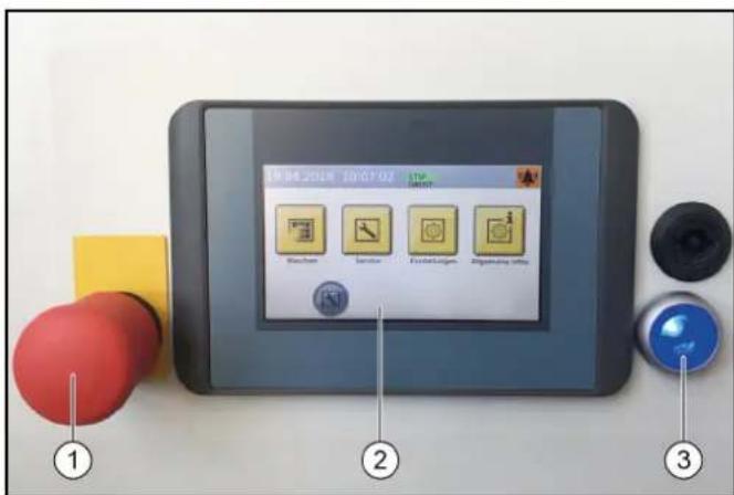
① KhoNka abapuHoiOCTaHOBKn
②KpaH
③ Khonkn ynpabnloe HnpanKeHn/ncxOndoro nnoJKeHn
D03npyuounhe HacocbI
MoIoune cpeCTBa n CpeCTBa dЯ yXOJa Do3npyIOCTC nOMOuBIO DO3npyIOxH HAcOCOB, KOToPbIe paCNoIOXKeHbIB KOnOHHe 2.
PacnoJoxeHne Do3npuyuixn Hacocob noka3aHO B KaueCTBe npimepa. IyoymuaHNO do3npuyuue Hacocb1-4 Bcerda pacnoJoxeHbl, KAK noka3aHO Ha KapTuHke.
YTO KacaetcAIO3npyuOux HAcOCOB 5-8,BbMoKeTe BbIbpaTb n37 pa3nnHbIX MOUxxCpeCTB u CpeCTB dna yxoJa.

DoznpyuOuHnHaoc
② D03npyuOuHn HAcOC, UAMnyHb
③ДоЗнруюшин haoc, nHa
④ Do3npyioui Haoc, B0ck 1
⑤Дозируюшин HAcOC,прдвapnteьня OчNTka (OT HaceKOMbIX)
⑥Доэпуюшн Haoc, Bock 2
⑦ДоЗИpyHоцин HAcOC, OuNCTka DnCKOB (HaHeceHne NeHbI Ha DnCKN)
⑧Доэнруюцин Haoc, noHPOBka
C NOMOUBIO D03NpyUOUIX HACOCOB MOUUINe CpeCTBa IN CpeCTBA IJRA yXODA IO6ABJIHOCTB B OBOY IJRA MOIKN B COOTBECTBUN C nporpaMMoI MOIKN IOCHAUEHEM YCTAHOBKN.
PpumeyaHue
Obembldo3upoeaHuaOnmumalbHo Hacmpaueaomc c6opukom 60 epema nepbozo eedeHu8 3KcnnyamauU ycmahoeku. Ka npaeuno, Hukaux u3MeHeu e Hacmpoukax He mpe6yemca.
06o3haeHne Do3npyOuix Hacocob
PpumeyaHue
Pacnoonxehue do3upyioux hacocoe 3aucum om KOHKpemHou ycmahOBku.
HeunpaBHOCTb yctaHOBKn
Khonna «TnabHnA»
C NOMOJIIO KHOIKN «TnABHAR MOXHO BbITN O6paTHO I3 NOdMeHO.

Tb30BaTeB BoWeI B CNTEmy

IocTaBzuk MOUoJero CpeDCTBa BOuEIN B CNTEmy

OnepaTop BOWen B CnCTemy

CneuaJIInCT IO o6cIyXuBaHnIO BOUeB CnCTEmy

Ce3oHHa nporpamMa MoKN, Becha

Ce3oHHa nporpamma MoKn, JeTo

Ce3oHHa nporpaMMa MoKN, OceHb
Ce3oHHa nporpamMa MoKn, 3IMa
MoiKa
B MeHIO «MoIka» MoKHO BbIbpaTb 3aNycTb nporpaMMbl I DOnONHHTeNbHbIe nporpaMMbl.
Tekyua nporpamMa MoKet 6bItb npeBaHa, INdkaun BblnoHHeN OTo6paKaETcB IIpoeHTax.
31.01.2019 17:25:59


1|Programm 1

4|Programm 4

2|Programm 2

5|Programm 5

3|Programm 3

6|Programm 6


CtpaHua 1/2

3anyck nporpaMMb MOKn, cm. 3anyck npo2paMMb c nOMoucbIO 3kpaHa.
CepBnC
PyHbIe cyHKun MOKHO BbIOJHHTb B cepBCHOM MEHIO 3aNyCTnTb pyHHyO 3aUHTy OT 3aMep3aHn.
31.01.2019 12:24:03


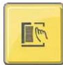
Punno npBdo
DnHnOCTnKa

CepBnC
CepBnchoe MeHcOedePknT CneDyUoJe IOnMeHIO:
pyuHoe ynpabIeHne (nopTaI c pyuHbIMn FyHKUaMn,pyuHO 3anyck 3aunTbI OT 3amep3aHnR,pyuHbIE FyHKUIN BOHOI CNCTeMbI);
- DnarHocTnka (ToIbKO onepaTopbI N o6cnyKnaIOuI npcoHaN); Bb3OB 0yHKUcMOnpOBePK yCTaHOBKn.
HactpoKn
MeHIO «HaCtpoKn» coDepknt Cnyk6bl aDMHNCTpnpOBaHnnoJIb3OBATeJIaMn, a TaOKe B HNX MOXHO 3aDaTb HaCtpoKn dIyctaHOBKn.
31.01.2019 12:00:47


AaMH. nonb3
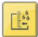
yp08.hanonH
MOU. CpeCTBa

OmbaHnΦopMaun
MeHIO «O6uaa HΦopMaunra» coepKNT cneDyUoune noDMHeIc:
CHETYKUKNIOBMOKNTOJbKOINOPA TOPOCMOTp3aBepueHHbIXNOTMeHeHHbIXUKNIOBMOKN;
Bpe mpa6oTbI;
- DnarHocTnka, Texnueckoe 6cnyKnbAHHe - CneDyUOuIN INHTepBaI TeXnueckoro 6cnyKnbAHna, CnCTEmHa INΦopMaun, KypHaI OUnbok, KypHaI CoBbITn;
- ypoBHN HANONHEHNA MOUUMN CpeCTBaMn -npoueHTHOe COepkaHne MOUUEO CpeCTBa (onu).
YBeDOMJIeHnHa 3KpaHe
Bo BpempaobtbyyctaHOBNMOYOTObpaKaTcHnHa3KpaHe cIeMyoune push-yBeDoMHeHn.
Kpntnuecka own6ka
3HaHTeJIbHaOwN6ka
B42KoHbIKn.HeorN.

Koheu. noJox. BHyTp./HapyK. OdHOBpem., npOB. KOHc. BbIKn, HhΦ. CepB.
F0212 31.01.2019 14:35:29


Co06ueHne 2/2

ONACHOCTb
Onachocmb u3-3a kpuueckou ouu6ku
Bbiknouhm ycmahOBky u cooobumb o6 owubke e cepuc. Kpumueckue ouu6ku Mozym 6bimy cmpaHbI monko luamu, komopbie 6blu obyuHbI mexHuueckomy 0cbnykuaHIO ycmaHO6ku.
Ecnn Bo3HnKaet HeckoIbKO Oun6OK, OHn 6yUT OTobpaKaTbcra HnpepbIBHO.
KJIaBnWcOCTpeKAMMMOYrNcNoIb3oBaTbcraDnrepeKnHeymMeXycoo6uHnMaM.
HcnpabHOctb
HencnpaBHOCTb
Cw foTopeNe, cepeHa
ΦoTopeIe cyu.,cepeiHa. PpOBep.,ouHCTnTb

YcTaHOBKa He B HcXoHOM NOIOXeHN
31.01.2019 17:10:26


YCTaHObKa He B nCX non!
HaKaTb KOnKy, TToobi nepem yCTAH. BNCX, NOONX
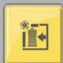

3TO COO5eHHe NOBnErc, KOrda arperat He HaxoNTcB NCXODHom NIOJKeHN.
PpumeyaHue
Haxmume KhoNky (Button) (>2cekyh unu cunHO KhoNky (> 2cekyhbl), ymo6bl nepemecmumbycmaHoey e uCxOHOe noJIOKeHue.
Bpem npoBeHn TExHnueckoro 06cnykBaHn
31.01.2019 13:42:59

Tpe6. texo6cn.
DorOBop.o
DateTexo6c.


Co06uHHe NoBnTcK, KOrDa HAcTynae BpEm dIa TexHnueckoro 0bCnykBaHH.
PpumueaHue
C8a3b6c cepBUCOM dna ha3haeHua epemHu npoeoehua mexHuecko0o ocbnykueahu.
BbD B 3KcnIpyatauio
- OtkpbItb 3anOpHbIe KJanaHbI dR BoDb I cKaTOrO B03dyxa.
- UCTAHOBNTB TnABHbBbIKNtATEnb Ha pacnpedeNTeNE NITAHNA B NONOKeHne «1»
- HaxaTb Ha cnHIO KhoNky ynpabJIOIero HanpJKeHH/ CXxOHoro noLOKeHHe Ha naHeN ynpabJeHH.
YcTaHOBka rOToBA K3KcNpyaTuIN. TpaHcNopTHoe CpeDCTBO, KOtOpoe Heo6xOIMOMbItb, MoXHO 3ae3KaTb B YcTaHOBky.
3Kcnpnyatauia
ONACHOCTb
Onachocmb u3-3a deuxyuxxca meu ycmHo
B cnyae 803HukHObeHua onachocmu dna IIOdeu, Umyuecema u XUBOMbIX HemeDJIeHNO omKnIOHume ycmaHO6Ky, Haxae KhoNky aapuHou ocmHO6Ku.
BHIMAHHE
Onachocmb noepekdeHm pahcnopmhbix cpedcme u3-3a He nonho2 ydaenHmu MOUe2o cpedcmea
Ecnu nocne haheceHua MOUe2o cpedcmea 803Hkaem HeucnpabHocmb 8 paobme moeHou ycmaHOBku, Heo6xodmo ydanumb MOUee cpedcmeo cpa3y nocne ebIKnOHeu YcmaHOBku, muaembeHo Cmbl8 e2o bdou, ymo6bl npedomepammb 803MOXHoe noepexdeHue kpacku u3-3a cnukom dNumenbHO2o 803deUcmBu MOUe2o cpedcmea.
PpumeyaHue
Ipu ucnolb3o8aHuu ycmaHOeOK drrc amoo6cnykuaHua
ece2da donxken npucymcmbo8amb yeNo8ek, 3HaKOMbu C
pa6omou ycmaoEku, komopbu moKem ebInonHumb unu
npunrmb Heo6xodumble MepbI, UMObU u36exAmb kaOu-1u60
onacnocmu.
BknHcHHe nocne abapnHOIOCTaHOKIN
PnpuMeaHue
Ipeod noBmOpHbIM 3anyckOM ycmpaHumb npuHy, no KomopoB 6blna 3adeUcmeOBaHa KNOnka aeapuHou ocmaHO6Ku. Iodu unu JxueomHbI He donXhbl HaxoDumbc8 paOoe3OHe. TpaHcnopMbIe cpedcMea doXhbl HaxoDumbc3a npedemaMOeHbIX ycmahOBok.

① KhoIIka abapnHoiOCTaHOBKn
② Khonkn ynpablaHooero HanpJxKeHn/ncXoHOro nIOJoxHeHn
1. Notaryb KhoNky abapuHou octaHOBKn, pa3boknpoBaTbe ee.
2. HaxaTb Ha cHIO KhoNky ynpabIyioero HanpIXeHN/ nCXoHOrO nIoXeHHe Ha naHEn ynpabIeHnB NcXoHOM nIoXeHm 3arOpaETc BepxHra 3eHnA cnHaJIbHa JAmna «BnepeJ» Ha cBeToΦope DnIXeHn.YctaHOBka ChOba roTOBa K nCNoIb3OBaHnIO, TpaHCnOpTHoe CpeDCTBO, KOtOpoe Heo6XoDMo NOMbITb, MOKet 3ae3KaTb B MoeHyIO yCTaHOBky.
Abtopn3aun noIb3oBaTeJypee3KpaH
1.BIABHOM MeHO Bb6paTb《HaCTpoKn/aDMNHNCpnpOBaHne NOB3OBATeJMAH》.
BydyT OTO6paXeHbI BO3MOXHbI BapnaHTbI Bbl6opa nonb3ObaTeJI.
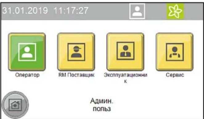
- BbIpaTb HxKHorO NOIb3OBaTeNIA OTKpoETcOKHO DnB BBOda KOna.
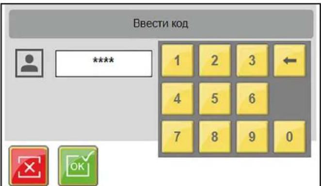
- BBeCTn KOd n IOdTBePdntb.
3nak ABTOPN3OBaHHORO NONb3OBaTeIg OTO6pa3ntcB BepxHei CTPOKe.
PpumeyaHue
Iio6o ypo8eHb noB30aemna aeomamuuecku 6pcabieBaemcdo ypo8n noB30aemna nocne 30 Muhym 6e3deucmbua.
Ioprotobka aBTOMO6nna
BHIMAHVE
PoepeKeHue ycmaHoeku u aemomO6un
Ppocneumb, ymo6bl nepeo 3anyckom ycmaHO6ku 6bln npunmb Mebp npedocmopoxhocmu no npedomepauehuo noepexdehu ha aemomobune.
- 3akpbItb OKHa, DBepn IIOK Ha KpbIiE.
- 3aDbHbTy bAHTeHHbI, CNOXNTb NIN CHrTb B HApBaBHeHH 3aDHeY qACTN.
- Onyctntb 60nbwoe nn daeneko Bbdaiooeeec 3epkaio.
- Ocmotpeb abTomauHy ha HAnuHne He3aKpenHeHHbx DeTaeNn CHrTb Nx, HanpImep:
MOJDNHΓN,
cnoiIep,
- 6amnepbbl,
pyuKn DBepei,
BbIXIOHbIe Tpy6bl,
BETPOOTpKaTeJIbHbI ΜιNTOK,
6pe3eHTObbl TPOcbI,
pe3nHOBBie ynnIOTHNTeIN,
yctahOBHeHbIe ChapyxN COHcEaUNTHbIe KO3bIPbKn,
- 6araXHHK.
Bbe3d TpaHcnpTHoro cpectBa
CBeToOp DnIXKeHnI NOMoAe KInHeTy ABTomOKn npaBnIbHO paCNOJoxNtCBOe TpaHCnOpTHoe CpeCTBO.
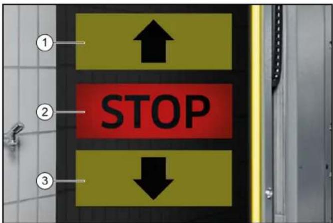
①ExaTB BnepeD
② CToT, paCnoJoxKeHne npaBnJIbHoe
3ExaTb Ha3a
- Tomecntb TpaHcnpTHoe CpeDCTBO nprmo n no ceHTpy MEXdy KOJIeenn.
Pocne toro, kak TpaHcnpThoe cpeIcTBO 6bINO paonoloxeHO npaBnIbHO
- BbIKIOHTb DBIRATeINb
- BkHouHTb nepeDaay.
- Ha aBToMaTnuecko Kopo6Ke Ipepeaay BbIbpaTb nIoXeHne «P».
- 3aTMyHyb pyuHoi TopMo3.
- Поберпь сбюндени BCex yka3aHи n3 pa3dena Iodzomobka abmombouna.
- TpAHCnOPTHOe CpeCTBO (kacaetcBceHIOeJ).
- 3anyctntb nporpammy MOKn B 3aBNCMOCTN OT Tnna 3anycka.
3anyck nporpammbi
Yepe3 cHTbIbATEJIb KapT/KoIOB
PpumeyaHue
Paboma co chumbIaIem KApM/kOdoe onucaHa o omdeIbHou uHcmpykuu no 3KcNnyamaauu dRn Cchmbieamena MoeHbix Kapm/kOdoe.
3anyck nporpammbic nOMOuBIO 3kpaHa
- BbIBeCTn TpaHCnOpTHoe CpeDCTBO n3 yCTaHOBKn.
PuynoynpaBneHne
Puyhhe yHKm MoryT 6bItb 3anyueneHbI dnn cneDyUxN x y3IOB:
- n o p t a n -pepeDnBxkeHne;
BepxHra 1eTka- DnHexHe BBePx N BHn3, BKIOueHne N BblKJIouHeHne;
6OKOBaJUeTKa-DBNKeHNE K N OT TpaHCnOpTHORO CpeIcTBA, BKNIOHHe H BbIKIOHHeH;
CywnJka—DbNKeHne BBepx N BHn3,BKIOueHne N BblKnOueHne;
KonechajIeTkA-DBNKeHne BnpeDHa3aD,BKIOUeHne N BbIKIOUeHne. - B rIaBHom MeHIO BbIbpaTb «CepBnC/PyHOn peKmPpHOn npTan».
OTkpoeTcMeHIO INCNOJIHReMbIXpyHbIXyHKU.
31.01.2019 10:53:52


Topan

B

60.1

Cytinno

Konec. get


- BbIbpaTb HxKbIy3eI.
BbIbpaemblepyHbIe yHKun6yDyT OTo6paKaTbcr KJITbIM CBETOM. - 3anyctntb pyuhyo dyHKnIO.
Ipejde yem Bb6paTb npyroyn y3en, Heo6xoJIMO OTMeHHTb Bb6op Bb6paHHoro y3na.
3anpaBka MOUoHxCpeCTB IN CpeCTB dIyXOda △PENEYNPEXKDEHNE
Onachocmb u3-3a xumueckux eeuece me
Cobnodamnb nacnpma bezonaacnocmu moouux cpedcme u cpedcme dny yxoda.
Ppumeyaue
Ha 3kpahe Haxamb KhoNku «Obua unHopmauur» u «UpoBu HanoHHeHu MOUUM CpedmeAmu», omobI omobpaumb yoBu HanoHHeHu, cm. Obua unHopmauur.
Hukamop ypoBHa HanonHeu ReJemaOnuue.
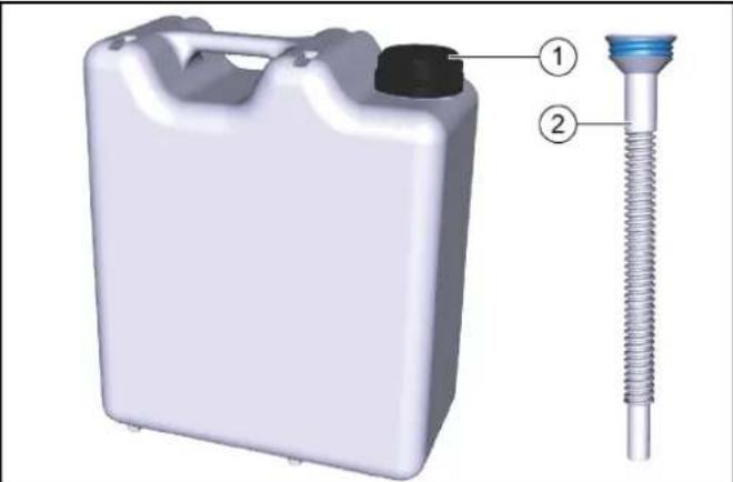
10 3anpaBoUHaKaHnCTpa
② Tpy6ka dny npejlnBaHn
- HABINHTIb Tpy6ky dny nepenBaHnHa 3anpaBOHyo KaHnCTpy.
- OTKpbITb COOTBETCTBYUOuN 6aK C MOIOUIM CpeICTBOM ININ CpeICTBOM IIN YXOJa.
- 3annoHnTb 6aKn n 3akpbTb CHOBA.
BbIBoN3 3KcnnyatauN
BbBOd n3 3KcNpyatauHa KopoTKn cpoK
- 3aKoHHTb DeIcTByUOyU npOrpaMMy MoKN.
- OctaBnTb TnabHb BblKlNoHateNb B NoIooKeHN «1», YTO6bI ONuHOHaNbHoe ycTpoCTBO 3aUHTbI OT 3amep3aHnR MoTIO OCTaBaTbCRAkTNBnPoBAHHbIM.
DolrocpoHna npocTaHOBka 3KcnIyatauN
- 3aKoHnHTb DeIcTByIOuI npOrpAMMy MoKN.
2.CnITb BOy I3 BCEX BOIOPOBOHbIX Tpy6,ecNHa BpemBbIBOda I3 3KcIpyatauON OxNDAOTC MOp03bl.
3.YcTaHOBnTbIaHBbI BbIKIOuHaTeNbBNOIOXKeHHe 0 - NpeekpbTb noaay Bobl
- NpeekpbTb noauy cKaTOro BO3nyxa
- YdaJIITb YnCTaIe e CpeCDtBO n CpeCDtBO dIyXoJa.
BbIBoN3 3KcPnPyTaaunC NOMOsbIO aBTOMaTnueCKOrO yCTpoNCTBa 3aUNTBI OT 3aMep3AHn(ONU)
BHIMAHHE
Ioepekdenue ycmahoeku u3-3a He 6knHoueHHo20 ycmpoucmea 3auumbl om 3amep3aHura
Ecnu cyuecmeyem puck 3amep3aunu, y6edumecb, ymo 2na8HbI 6bIKIOUcmeJI bKIOUeH, a KONka aapuHou OcmahOeKu He Haxama.
Ecnn MmHmAbhA TeMnepaTpy Hnke, Yem OxNdaNoCb, ABTomatueckn 6dyT BblnoHrTbcra CneDyUOuNe waR.
- Tekyza nporpamma MoKb 6ydt 3aBepseHa.
- Nocne okohuaHn nporpaMMb MoKu IHaHn n fOpcyHKn nopTana npOdyBaHTc CxA TbIM BO3dyXOM.
- 3aynck daNbHeuHnX nporpaMM MoKn bdyet 3a6nKnpoBaH.
PpumeyaHue
Iocne mozo, kak onachocmb 3aMep3aHua uCye3Hem, ycmaHObKa aemomamuuecku cOba 6ydem zomoea K paBome
PyuHoi 3anyck aBToMaTnueckoro npocecca 3aunTbI OT 3aMep3aHnA
BHIMAHHE
Ioepekehue ycmaHOeku u3-3a memnepamyp Huxe moKu 3aMep3aHua
BbInonHumb 3auumy om 3aMep3aHua Ha ycmaHoKe.
PpumeyaHue
B ycmahoekax c aemomamuueckou 3auumou om 3amep3aHua 3auuma om 3amep3aHua 6KnIOHaemcra, KaK monbko docmu2aemc 3adahnagmemnepamypa.
31.01.2019 12:34:38


Hopran pyuH
3auntaoT aamepz,pyu.
PuyanmaoKa BDOI

Pyrno npBOD
- B rIaBHom MeHIO BbIbpaTb «CepBn/CpyHOn peKImM»
- HaxaTb KhoNky «PuyHra 3aunTa ot 3amep3aHnra», YTO6bl 3anyCTNTb 3aunTy ot 3amep3aHnra. Ipon3oJedet 3anyck 3aunTbI ot 3amep3aHnra, a OCTabWeeecr Bpem oTo6pa3ntcHa 3kpaHe.
31.01.2019 13:25:03


60ircC
00:24:48

3aunta ot 3amep3.pyh.
YxOndTexHnueckoe 06cnyXnBaHne
Yka3aHnno TExHnueckomy 06cJyXnBaHHo
Baxhblm ycnobnem Hndexho paobtby yctahOBKn rBnertcpepynphoeTexHnueckoe 06cnykunBaHne B COOTBETCTBnC nHaHom TexHnueckoro 06cnykunBaHn.
△NPEDYNPPEKDEHNE
OnachocmbmpaMupo6aHuaU3-3a 6paauuuxcyaacmeu Maunhbl
BbiknouambMoeyHyO ycmahOBky neped npoBeDeHuem pa6om no mexHuueckomy ocbnyxueaHuo u codepxaHuo e ucnpaBHoCmu.
3aummb 2naeHbI nepeKIOyamEnb om noemopHOO 6KnOHeHua, Hapumep, c NOMoUbIO BUCyEzo 3Amka.
△PENDEUYNPEKDEHNE
OnachocmbmpaMupoeaHua3-3a ebinycka cKamoo 03dyxa u3 bannohu u coedunehu, haxoduxxcn oD daeJeHuem nocne ebiknoueHu ycmaHoeku
Cnyckamb daenehue neped npoeedeHuem nIObix paobom ha ycmahoeke.
Ppoeepom omycmmeue daeneHua Ha MaHomempe nheMo6noka.
△NPEDyPPEXDEHNE
OnachocmbmpaemupoeaeHua3-3a binycka cKamoo 603dyxa u3 cucmembic xkambim 603dyxom, haxodaeucnod daBHeuem nocne bIKIOueHu ycmaHOku
Ipepe bInonHeHem IIObix pabom c ycmaHOKo Cnyckamb daeneHue 6 cuCme Me bICOKO2O daeneHue.
△ONACHOCTb
OnachocmbmpaemupoeaeHua3-3a ebic6o6xdeHua cKamooe03dyxa, 0dbI NOB ebICOKUM daenHeuM Ha ebIXode u3 conla, a makke lemaux yacmu apra3u m. n. e 3OHe epauaouuxcx yemok!
Bbiceo60kaioueceyacmuuap3u unnpedmemmoym mpaemupoeambloe uunxueomhix.
Ckambl 8030yx unu 80da noD b6cokum daeneHEm moym ocmaeambcnoD daeneHEm, daxe ecnu ycmaHOeKa bbKIOUyeHa.
Codepkamb non e pa6oey 30he aemomouku yucmbim om He3akpenJIeHHbIX npedMemoe.
3Kcnnyamupyime ycmaHOky co cXaMbIM 603dyxOM unu Cucmemy bICOKO2o daBHeUR ocmopoxHo.
Bo spempa6om no mexHueckomy o6cnyku8aHIO uCnOb3oBam 3auumhble Ocu.
CeneBbIe rpynnbI no yxOdy n TexHnueckomy 06cnyKBAHHO
Komy pa3peSeHNO npOBoNDt NpOBePK, TexHnueckoe 06cIyKnBaHHe n pa6Otbl NO coepKaHaHNo yCTaHOBKn B nCnpaBHOCTn?
Onepatop
Pa60tbc nometkOg «OnepaTOp» pa3pewaaTcra npoBODITb TOLbKO pONHCTpyKTHpOBAHHbIM NlUcaM, CNOCOBHbIM 6e3OnaCHO ynpabnTb N O6CnyKINBaTb ycTaHOBky.
CepBnchna cnjx6a
Pa60tbc nometkOeCepBnchA cnYk6a)pa3peuaeTc npoBOIDNTb TOJIbKO TexHnueckmN CNEUaJINCaMn cepBnCHOH cnYk6bl KOMNaHnKarcher nn yONHMOHeHHbIMN KOMnHaHne Karcher cneuaJIncTaMn.
DorOBop Ha TexHnueeCKoe 06cnyKbAHne
YTo6blObeCneHTbHaTeKHyIO pa6Ory yCTaHOBKN,MBI peKOMeHnyEM Bam 3aKnIOHTb DoROBOP HaTexHnueCKoe
06cLyKnBaHne.ObpaTntecb B COOTBeTCTByIOUyIO cepBnCHyIO cnxy6by KOMNaHN KARCHER.
NoIroTobKa
Baawa co6cbenha 6e3oNaChocb n 6e3oNaChocb dpyrnx Tpebyet, yTo6bl yctaHOBka 6blna otKlIOHeHa Ha Bpemn npOBeHnra paobT no TexHnueckOMy o6cnykBAHnIO n coepKaHHB u nCnpabHOCtN. NockoJIbky He do BCex NOIeXaUHX O6cLyKnBaHHIO KOMNoHEhTOB yCTaHOBKn eCTb DOCTyn, ONpeDeneHHbIe KOMNoHEHTb yCTaHOBKn DOnJHbI bItb NepeDbHHTb BO Bpemr paobT no TexHnueckOMy o6cnykBAHHIO n coepKaHHN B nCnpabHOCtN. IJa 3TORo npedymOTpeh peXm pa60bl «PyhoH peKIM»
Puyon pexim 3aynyckaetca Ha ekpahe.
ONACHOCTb
Onachocmbmpaemupoehua
Osbamno cneobam npueedeHomy Hxke npoky ebnonHeu deucmeur.
BHIMAHNE
Onachocmb noepekdeHua3-3a pyhno ynpaeJeHure He uonb3oabMb pyhou pekum dna MouKmpaHcnopmBix cpedcm.
- BbIBeCTn TpaHcNOpTHoe CpeIcTBo N3 yctaHOBKn.
- Y6eIITbcra, YTO B yCTaHOBKe HET IIOJe NJIIN JXNBOTbIX.
- BkInouHt b yCtahOBky.
- BbIbpaTb pyHoi peXIM Ha 3KpaHe.
- NepemecNTb KOMnOHeHtbl yCTaHOBKn.
- BbIKIIOHTy yCTaHOBky 3a6NOKIpOBaTb OT NOBTOPOBBOKIIHOYEHJ.
- BbINOHNtB paOToI NO TexHnueckomy 06cnyKnBaHIO n COepeKaHHo B INcpaBHOCTN.
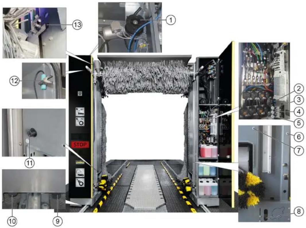
063op texnueckoro 6cnyxbanna, nueba ctopoHa nopTa
POMOuB npH HncnpaBHOCTaX
△PENEYNPEXKDEHNE
Onachocmbmpaemupoeahua3-3aepauaouxcyaomeu Maunhbl
BbiknHouambMoeyHyu ycmahOBky neped npoBeDeHuem paobm no mexHuueckomy ocbnykueaHu u codepKaHu e ucnpaBHoMu.
3aummb 2aehb nepeknquamnb om noemopno0
EKNOeHua, Hnnpmep, c nOMoub6ucayeo 3Amka.
△PENEYNPEXKDEHNE
OnachocmbmpaemupoeaeHua3-3a ebinycka cKamooe 0o3dyxa u3 bannohu u coedunehu, haxoduxxcn od daenHeum nocne ebiknoueHura ycmahO6ku
Cnyckamb daeneHue neped npoeedeHuem nO6bix pa6om Ha ycmahoeke.
Ppoeepm b omycmmeue daeneHua Ha MaHomempe nHeMo6noka.
△NPEyIpyKJDEHNE
OnachocmbmpaemupoeaHua 3-3a binycka cXamooe 03dyxa u3 cucmemblc xkambm 03dyxom, haxoaeuecn nood aabeHeuem nocne 6bIKIOueHu ycmaHO6ku
Ipeo e binoHHeuem nObix paobc ycmaHOaKou cnyckamb daeneHue e cucmeme ebicoko2o daeneHue.
LcJIeBBIe rpynnbI dIyCTpaHeHnHEncnpaBHOCTe KTo dONXeH yCTpaHrTB HeNCnpaBHOCTn?
Onepatop
Pa60tbc nometkOe OpeaTOpPapeaetc npoBOnTb TOnbKO pONHCTpyKTHPOBaHHBM Nuaam, cNOC6HbIM 6e3OnaCHO ynpabTb N o6CnyXnBaTb yctahOBky.
KbannuHnupoBaHHbe 3JneKtpnK
KbaHnΦuHpOBaHHbIe 3JKeTpUKN — Nua, NOyUWBne npocceCNOHaBHyo nOtroBky B o6NaCTn 3JKeTpoTeXHNIK.
CepBnchna cny6a
Pa60tIc nometko «CepBnchA cnyk6a» pa3pe7aetc npoBOIDMb TOnbKO TexHueckMm CneuaJIncTAmu cepBnCHO n cyjkbKOMNaHm Karcher nn ynonHomOeHHbIMN KOMnHaHne Karcher cneuaJIncTAmn.
Hnkaun HecnpapBHOHa 3KpaHe
PpumeyaHue
Heucnpa6Hocmu c yka3aHuem npuUHHb U 803MOxHocmu ux ycmpaHnur om6paXaHOMcna Ha 3KpaH e eude meKcma.
3HaHTeJIbHaOwN6Ka
B42 KOH.BbIKn.HeIorN.
Koheu.nIOX.BHyTp./HapyK. OJHOBpEm.,npOB. KOHc.BbIKn.IHΦ.cepB.
F0212 31.01.2019 14:35:29

CoobueHne 2/2


YcTpaHnTb HEnCnpaBHOCTb B COOTBeTCTBm C yKa3aHnMaHa 3KpaHe nNoTBePHTb HaxaTne KHOJKN OK.
HdNkaunHa CBeToOpoe DnHexn
HeHcnpaBHOCTn 6e3 Hndkaun
Chairman of the Board of Management

S. Reiser
Manager Regulatory Affairs & Certification
JIuO,OTBtCTBeHHoe3aBeDeHHeIOKymeHTaUIN:
II. Pau3ep (S. Reiser)
Alfred Kärcher SE & Co. KG
Alfred-Karcher-Str. 28-40
71364 Winnenden (Germany)
Ten.: +49 7195 14-0
ΦaKc: +49 7195 14-2212
r.BHHHeHdeH,01.11.2022
Tartalom
Chairman of the Board of Management

S. Reiser
Manager Regulatory Affairs & Certification
Winnenden, 2022/11/01

THANK YOU!
MERCI! DANKE! iGRACIAS!

Register your product and benefit from many advantages.
www.kaercher.com/welcome


Rate your product and tell us your opinion.
www.kaercher.com/dealersearch
Alfred Kärcher SE & Co. KG
Alfred-Karcher-Str.28-40
71364 Winnenden (Germany)
Tel.: +49 7195 14-0
Fax: +49 7195 14-2212


- Reiser
- Contents
- General notes
- Environmental protection
- Notes on the content materials (REACH)
- Safety instructions
- Hazard levels
- △DANGER
- WARNING
- CAUTION
- ATTENTION
- Regulations and guidelines
- Vehicle washing plants
- Waste water containing mineral oil
- Self-service
- Maintenance and servicing
- Operation with detergent
- Entering the portal washing station
- Risk of slipping
- Operating the system
- △WARNING
- Danger of frost
- Workstation
- Danger sources
- General dangers
- Risk of explosion
- Note
- Hearing damage
- Electrical hazards
- Danger of electric shock
- Substances harmful to health
- Danger due to harmful substances
- Danger due to power failure
- Environmental hazard due to waste water
- Servicing and monitoring
- Risk of injury from machine movements
- Monitoring
- Use only original parts
- Safety devices
- Safety valve
- Intended use
- Risk of damage to vehicles when using the CareTouch brushes
- Be aware of the dimensions
- Water connection
- Erection
- Foreseeable misuse
- Material damage to vehicles and the system if the vehicle dimensional limits are not adhered to
- Unsuitable detergents
- Increased risk of corrosion through the use of unsuitable cleaning agents
- Accessories and spare parts
- System description
- Overview of the entry side of the system
- Standard equipment
- Side brushes
- Roof brush
- Wheel washing unit (circular broom)
- Nozzles and spray arches
- Foam wash
- Dirt traps
- Dosing pumps
- Dryer side nozzles
- Roof drier
- Positioning light
- Light sensors
- Cleaning and care agents
- Type plate
- Control cabinet
- Supply distributor
- Emergency off
- Operating station
- Tilt protection
- Options
- Wash card reader/code reader
- Process water connection
- Planet wheel washing unit
- Height-adjustable wheel washing unit
- Wheel well cleaning
- Underbody washing unit
- Prespraying (remove insects)
- Intensive Basic
- Wheel rim foam
- High-pressure wash
- Foam wax
- Cold wax
- Cleaning agent heater
- Frost protection device
- Reverse osmosis system
- Foam polishing
- Safety switch
- Splash guard
- Bollard protection
- Remote reset
- Gate control
- Summer gate control
- Winter gate control
- Control elements
- Main switch
- ABS payment system
- Wash card/code reader
- Labelling of the dosing pumps
- Adjusting the dosing amount
- Damage to the dosing pump due to dry running
- Vent the dosing pump
- Display description
- Start display
- Status bar
- Description of symbols
- Washing
- 17:25:24
- Service
- 12:23:28
- Settings
- 11:57:35
- General Info
- 17:18:35
- Messages on the display
- Critical fault
- SB2 Position not logical
- Malfunction
- Dryer LightbarrierMiddle
- Event
- Position Right Wheelwasher
- System not in initial position
- Service required
- Start-up
- Operation
- DANGER
- Switching on again after an emergency off
- Log in the user on the display
- Preparing the vehicle
- Damage to the system and the vehicle
- Driving in the vehicle
- After positioning
- Starting the program
- At the wash card/code reader
- Start the program on the display
- Interrupting the currently running program
- Programme end
- Manual mode
- Refilling the cleaning and care agents
- Danger due to chemicals
- Shutting down
- Short-term shutdown
- Long-term shutdown
- Shutdown via the automatic frost protection device (optional)
- Damage to the system if the frost protection device is not switched on
- Manually starting the automatic frost protection process
- Damage to the system through temperatures below zero Execute the frost protection process for the system.
- Care and service
- Maintenance instructions
- Risk of injury from pressurised compressed air reservoirs and lines after the system has been switched off
- Risk of injury from the high-pressure system after the system has been switched off
- Target groups for care and maintenance
- Operator
- Customer Service
- Service contract
- Preparation
- Rear portal maintenance overview
- Hall maintenance overview
- Machine room maintenance overview
- Daily maintenance plan
- Maintenance work
- Clean the pressure reducer strainer
- Check the float switch
- Troubleshooting guide
- Qualified electricians
- Fault messages on the display
- Venting the centrifugal pump
- Warranty
- Water and detergent consumption
- Declaration of Conformity
- EU Declaration of Conformity
- Currently applicable EU Directives
- Harmonised standards used
- Declaration of Conformity (UK)
- Currently applicable UK Regulations
- Contenu
- Pollution due aux vehicules
- Installation reverse-osmose
- Indices
- Inhoud
- Langdurig stilleggen
- Indices de Contents
- Interruptor principal
- Observar as dimensional
- EL2 Interruptor final ilogico
- Indhold
- Tilkobling after nodstop
- Obs
- Innmatingsfordereler
- Anvendte harmoniserte standarder
- Innehalle
- Forsprutting (losa spp. insecter)
- Sisälto
- CopepxaHne
- 06uyeyka3aHn
- Yka3aHnno KOMnHOHeTAM (REACH)
- CTeneHb onaCHOctN
- ONACHOCTb
- △NPEyPEXKDEHNE
- △OCTOPOXHO
- BHIMAHHE
- PpeDncaHnI NnpeKtnBbl
- PpumeyHue
- △NPEUYPEXKDEHNE
- Onachoctn, BblbBaemble 3neKtpueecknH anpaeKeHHem
- OnachbIe dIy 3dOpOBb BeueCTBa
- OnachocbBpe3yNbTaTe c6oNtAHn
- OnachocbOkpykaohuei cpeoTc0hBix BOI
- Copepkanhe BncnpaBHOCTn Ha3Op
- Texnueckoe obcnykBaHne n coepkaHne BncpabHOCTN
- △NPEDYNPPEKDEHNE
- △PENDEUYNPEKDEHNE
- △NPEDYNPEXDEHNE
- Had3op
- IcnoB3OBAbOpHnHaJIbHbIe DeTANI
- PpeoxpahnteBhieyctpoiCTBa
- PpeOxpaHnTeJbHbI KnanaH
- IcnoNb3OBAHHe no Ha3HaueHnIO
- BHIMAHNE
- Co6nIeHne pa3MepoB
- PnOaBOD BoAbI
- MOHTAX
- YmbiHHeHoe HnpeBaBnBHOe npImeHeHne
- IoepekehdeHue mpaHcnopmhbix cpedcme u ycmaHOku 3a HecobnOeHua npedeBbix pa3Mepo8
- HenpiroDhbie YnctTae CpeAdTba
- NoBbWeHHa onachocmb Koppo3uu ecJeDcmeue npumHeHn HenoDxOraeoo Yucmaeoo cpedcmea
- PpHaIeXHocTn 3aIacHbIe YacTn
- OnncaHne MoeUHOyycTaHOBKn
- 06nBmOeHOnyCTaHOBKnCoCTOpOBbBbe3da
- CTaHdapTHa KOMnEKeTaIgA
- Bokobblie 1eTkn
- BepxHra 1eTka
- Annapat nnynckkoilec (Tapebataa tke)
- PpumueaHue
- OpcyHKn npacnbIINTeJIbHbIe apKn
- Mouka c neHoi
- Bpb3ROBNK
- D03npyuüne hacocbI
- Bokobbie fopcyhcuwn
- Bepxny cywnka
- CBeToΦop DBnXeHn
- Φotopene
- Moouee cpeCTBO n cpeCTBa dny yxoDa
- 3aBODCKa Ta6JIuYka
- UkaynpaBneHn
- Pacnpedentenb nTaHn
- AbapnHoe ocTaHOBka
- IyHKt ynpaBHeHH
- 3aunTa OT onpOKnDbIbAHNA
- DononHHTeJbHo
- CuntbIbATEnbkapT/KoIOB
- PpumeyaHue
- TnKluoyHe texHuecko BOdbI
- PnaHetapbI annapaT dIy nCTKoNEc
- Perynpemybno BBicote annapat dny nctkn konec
- UncTka KOJIeCHbIX HnW
- 06opydoBaHne dIa OuNCTKn DnHua
- PpeBapnteIbHoe paCnblHeHne (ydaJIeHHe HaceKombix)
- Ba3OBa HHTeHCBHbOuNTKa
- HaHeceHne neHbHa dNcKn
- MoKa nO BbICOKM DaBHeHneM
- Пechнь ВOCK
- XoJOnHbI BocK
- HarpeBaTeB MoUoIero CpeDCTBa
- 3aunTa oT 3amep3AHN
- YctaHObKa 06paTHoro OCMoca
- Ponipovka neHoi
- PpeoXpaHnTeIbHbIe BbIKNoUaTeJN
- БpbI3ROBnK
- KoIecooTbOHHbIe Tym6bl
- DuctaHNoHHbI c6poc
- UnpabJIeHHe BOpOTAMN
- UnpaBHeHne BOpTaMn IJNeTHeRo Ce3OHa
- YnpaBHeHne BOpTaMn INa 3mMHeRo Ce3OHa
- 3nemeHbI ynpaBJIeHnA
- AbarHoe ocTaHOBka
- TnaBbI BbIKJIOHaTeJIb
- CnCTema CynCHeHNABS
- CunTBiBaTeNb KapT/koIob
- Pahenb ynpaBneHn
- D03npyuounhe HacocbI
- 06o3haeHne Do3npyOuix Hacocob
- MoiKa
- CepBnC
- HactpoKn
- OmbaHnΦopMaun
- YBeDOMJIeHnHa 3KpaHe
- Kpntnuecka own6ka
- 3HaHTeJIbHaOwN6ka
- B42KoHbIKn.HeorN.
- HcnpabHOctb
- HencnpaBHOCTb
- Cw foTopeNe, cepeHa
- YcTaHOBKa He B HcXoHOM NOIOXeHN
- Bpem npoBeHn TExHnueckoro 06cnykBaHn
- BbD B 3KcnIpyatauio
- 3Kcnpnyatauia
- BknHcHHe nocne abapnHOIOCTaHOKIN
- PnpuMeaHue
- Abtopn3aun noIb3oBaTeJypee3KpaH
- Ioprotobka aBTOMO6nna
- BHIMAHVE
- PoepeKeHue ycmaHoeku u aemomO6un
- Bbe3d TpaHcnpTHoro cpectBa
- Pocne toro, kak TpaHcnpThoe cpeIcTBO 6bINO paonoloxeHO npaBnIbHO
- 3anyck nporpammbi
- Yepe3 cHTbIbATEJIb KapT/KoIOB
- 3anyck nporpammbic nOMOuBIO 3kpaHa
- PuynoynpaBneHne
- 10:53:52
- 3anpaBka MOUoHxCpeCTB IN CpeCTB dIyXOda △PENEYNPEXKDEHNE
- BbIBoN3 3KcnnyatauN
- BbBOd n3 3KcNpyatauHa KopoTKn cpoK
- DolrocpoHna npocTaHOBka 3KcnIyatauN
- BbIBoN3 3KcPnPyTaaunC NOMOsbIO aBTOMaTnueCKOrO yCTpoNCTBa 3aUNTBI OT 3aMep3AHn(ONU)
- PyuHoi 3anyck aBToMaTnueckoro npocecca 3aunTbI OT 3aMep3aHnA
- 00:24:48
- YxOndTexHnueckoe 06cnyXnBaHne
- △NPEDyPPEXDEHNE
- △ONACHOCTb
- CeneBbIe rpynnbI no yxOdy n TexHnueckomy 06cnyKBAHHO
- Onepatop
- CepBnchna cnjx6a
- DorOBop Ha TexHnueeCKoe 06cnyKbAHne
- NoIroTobKa
- Onachocmbmpaemupoehua
- POMOuB npH HncnpaBHOCTaX
- △PENEYNPEXKDEHNE
- △NPEyIpyKJDEHNE
- LcJIeBBIe rpynnbI dIyCTpaHeHnHEncnpaBHOCTe KTo dONXeH yCTpaHrTB HeNCnpaBHOCTn?
- KbannuHnupoBaHHbe 3JneKtpnK
- CepBnchna cny6a
- Hnkaun HecnpapBHOHa 3KpaHe
- B42 KOH.BbIKn.HeIorN.
- Tartalom
- THANK YOU!
- MERCI! DANKE! iGRACIAS!
Brand : Kärcher
Model : CW 3 Klean!Star
Category : Car Wash