
PV 1015D - Loudspeaker PEAVEY - Free user manual and instructions
Find the device manual for free PV 1015D PEAVEY in PDF.
| Product type | Two-way active PA speaker |
| Dimensions (H x W x D) | 700 x 461 x 429 mm |
| Weight | 25.4 kg |
| Power supply | 100-120 V~ / 220-240 V~, 50-60 Hz (selectable) |
| Nominal power consumption | 370 W |
| Fuse (100-120 V~) | T6.3AL, 5x20 mm |
| Fuse (220-240 V~) | T3.15AL, 5x20 mm |
| Amplifier | Class D with DDT compression |
| Total peak power | 800 W |
| Continuous power (into 4 ohms) | 400 W |
| Frequency response | 63 Hz - 18 kHz (±3 dB) |
| Sensitivity (1W/1m) | 95 dB |
| Max SPL (peak) | 121 dB |
| Woofer | 15" Sheffield with 2 3/8" voice coil and 50 oz magnet |
| Tweeter | RX14 compression driver with 1.4" titanium diaphragm |
| Coverage (H x V) | 100° x 50° (vertical asymmetrical +15°/-35°) |
| Crossover frequency | 2.8 kHz |
| Inputs | 1x female XLR / 1/4" TRS combo balanced or unbalanced |
| Outputs | 1x Link Out (1/4") pre-level, 1x Speaker Out (1/4") for passive speaker 8 ohms min. |
| Protection | DDT anti-clipping, subsonic filter, fuse, thermal protection |
| Additional features | Contour switch (bass/treble boost), voltage selector |
| Cabinet material | 15 mm MDF |
| Finish | Black carpet, perforated steel grille |
| Included accessories | IEC power cord, pole mount adapter |
| Maintenance and cleaning | Disconnect before cleaning, use a dry cloth |
| Safety | Do not open, do not expose to water or moisture, use a grounded outlet |
| Reparability | Only a Peavey authorized technician may service |
Frequently Asked Questions - PV 1015D PEAVEY
User questions about PV 1015D PEAVEY
0 question about this device. Answer the ones you know or ask your own.
Ask a new question about this device
Download the instructions for your Loudspeaker in PDF format for free! Find your manual PV 1015D - PEAVEY and take your electronic device back in hand. On this page are published all the documents necessary for the use of your device. PV 1015D by PEAVEY.
USER MANUAL PV 1015D PEAVEY
Class-D Powered Two-Way Sound Reinforcement Speaker System
natural_image
Black rectangular electronic device with 'PV SERIES POWERED' branding and a circular logo on top (no readable text beyond branding)Operating Manual

Intended to alert the user to the presence of uninsulated “dangerous voltage” within the product’s enclosure that may be of sufficient magnitude to constitute a risk of electric shock to persons.
Intended to alert the user of the presence of important operating and maintenance (servicing) instructions in the literature accompanying the product.
CAUTION: Risk of electrical shock — DO NOT OPEN!
CAUTION: To reduce the risk of electric shock, do not remove cover. No user serviceable parts inside. Refer servicing to qualified service personnel.
WARNING: To prevent electrical shock or fire hazard, this apparatus should not be exposed to rain or moisture, and objects filled with liquids, such as vases, should not be placed on this apparatus. Before using this apparatus, read the operating guide for further warnings.

Protective earthing terminal. The apparatus should be connected to a mains socket outlet with a protective earthing connection.

Logo referenced in Directive 2002/96/EC Annex IV(OJ(L)37/38,13.02.03 and defined in EN 50419: 2005 The bar is the symbol for marking of new waste and is applied only to equipment manufactured after 13 August 2005
Correct Disposal of this product. This marking indicates that this product should not be disposed with other house hold wastes throughout the EU. To prevent possible harm to the environment of human health from uncontrolled waste disposal, recycle it responsibly to promote the sustainable reuse of material resources. To return your used device, please use the return and collection systems, or contact the retailer where the product was purchased. They can take this product for environmental safe recycling.


FCC Compliancy Statement
This device complies with Part 15 of the FCC rules. Operation is subject to the following two conditions: (1) this device may not cause harmful interference, and (2) this device must accept any interference received, that may cause undesired operation.
Warning: Changes or modifications to the equipment not approved by Peavey Electronics Corp. can void the user's authority to use the equipment.
Note - This equipment has been tested and found to comply with the limits for a Class B digital device, pursuant to Part 15 of the FCC Rules. These limits are designed to provide reasonable protection against harmful interference in a residential installation. This equipment generates, uses and can radiate radio frequency energy and, if not installed and used in accordance with the instructions, may cause harmful interference to radio communications. However, there is no guarantee that interference will not occur in a particular installation. If this equipment does cause harmful interference to radio or television reception, which can be determined by turning the equipment off and on, the user is encouraged to try and correct the interference by one or more of the following measures.
- Reorient or relocate the receiving antenna.
- Increase the separation between the equipment and receiver.
- Connect the equipment into an outlet on a circuit different from that to which the receiver is connected.
- Consult the dealer or an experienced radio/TV technician for help.

IMPORTANT SAFETY INSTRUCTIONS
WARNING: When using electrical products, basic cautions should always be followed, including the following:
-
Read these instructions.
-
Keep these instructions.
-
Heed all warnings.
-
Follow all instructions.
-
Do not use this apparatus near water.
-
Clean only with a dry cloth.
-
Do not block any of the ventilation openings. Install in accordance with manufacturer's instructions.
-
Do not install near any heat sources such as radiators, heat registers, stoves or other apparatus (including amplifiers) that produce heat.
-
Do not defeat the safety purpose of the polarized or grounding-type plug. A polarized plug has two blades with one wider than the other. A grounding type plug has two blades and a third grounding plug. The wide blade or third prong is provided for your safety. If the provided plug does not fit into your outlet, consult an electrician for replacement of the obsolete outlet.
-
Protect the power cord from being walked on or pinched, particularly at plugs, convenience receptacles, and the point they exit from the apparatus.
-
Only use attachments/accessories provided by the manufacturer.
-
Use only with a cart, stand, tripod, bracket, or table specified by the manufacturer, or sold with the apparatus. When a cart is used, use caution when moving the cart/apparatus combination to avoid injury from tip-over.
-
Unplug this apparatus during lightning storms or when unused for long periods of time.
-
Refer all servicing to qualified service personnel. Servicing is required when the apparatus has been damaged in any way, such as power-supply cord or plug is damaged, liquid has been spilled or objects have fallen into the apparatus, the apparatus has been exposed to rain or moisture, does not operate normally, or has been dropped.
-
Never break off the ground pin. Write for our free booklet "Shock Hazard and Grounding." Connect only to a power supply of the type marked on the unit adjacent to the power supply cord.
-
If this product is to be mounted in an equipment rack, rear support should be provided.
-
Note for UK only: If the colors of the wires in the mains lead of this unit do not correspond with the terminals in your plug, proceed as follows: a) The wire that is colored green and yellow must be connected to the terminal that is marked by the letter E, the earth symbol, colored green or colored green and yellow. b) The wire that is colored blue must be connected to the terminal that is marked with the letter N or the color black. c) The wire that is colored brown must be connected to the terminal that is marked with the letter L or the color red.
-
This electrical apparatus should not be exposed to dripping or splashing and care should be taken not to place objects containing liquids, such as vases, upon the apparatus.
-
The on/off switch in this unit does not break both sides of the primary mains. Hazardous energy can be present inside the chassis when the on/off switch is in the off position. The mains plug or appliance coupler is used as the disconnect device, the disconnect device shall remain readily operable.
-
Exposure to extremely high noise levels may cause a permanent hearing loss. Individuals vary considerably in susceptibility to noise-induced hearing loss, but nearly everyone will lose some hearing if exposed to sufficiently intense noise for a sufficient time. The U.S. Government's Occupational Safety and Health Administration (OSHA) has specified the following permissible noise level exposures:
Duration Per Day In Hours Sound Level dBA, Slow Response
| 8 90 | |
| 6 92 | |
| 4 95 | |
| 3 97 | |
| 2 100 | |
| 1 1/2 102 | |
| 1 105 | |
| 1/2 | 110 |
| 1/4 or less | |
According to OSHA, any exposure in excess of the above permissible limits could result in some hearing loss. Earplugs or protectors to the ear canals or over the ears must be worn when operating this amplification system in order to prevent a permanent hearing loss, if exposure is in excess of the limits as set forth above. To ensure against potentially dangerous exposure to high sound pressure levels, it is recommended that all persons exposed to equipment capable of producing high sound pressure levels such as this amplification system be protected by hearing protectors while this unit is in operation.
SAVE THESE INSTRUCTIONS!
a) The wire that is colored green and yellow must be connected to the terminal that is marked by the letter E, the earth symbol, colored green or colored green and yellow.
b) The wire that is colored blue must be connected to the terminal that is marked with the letter N or the color black.
c) The wire that is colored brown must be connected to the terminal that is marked with the letter L or the color red.
Class-D Powered Two-Way Sound Reinforcement Speaker System
Thank you for purchasing the Class-D powered Peavey ® PV ® 1015D. The PV1015D is a two-way, self-powered sound reinforcement system based on a 15" Sheffield ® woofer and an RX ™ 14 titanium diaphragm dynamic compression driver mounted on a Peavey patented asymmetrical Quadratic Throat Waveguide ™ , with a coverage pattern of 100° by 50°. The PV 1015D features a Class-D power section that provides up to 800 peak available watts of power for the system, with DDT ™ compression. Input jacks provided are a balanced input XLR and a 1/4" phone combination jack, with a volume control and a Contour switch for boosting lows and highs.
FEATURES
- Two-way powered sound reinforcement enclosure
- Peavey exclusive 15" Sheffield woofer with 2 3/8" voice coil & 50 oz. magnet
- RX 14 1.4" titanium diaphragm compression driver
- Patented 100irc × 50irc Quadratic Throat Waveguide technology
- Asymmetrical horn directs the sound down to the audience
- Class-D powered system with up to 800W total peak available power
- DDT compression/anti-clipping protection
- Signal input via combination female XLR and 1/4" jack, providing balanced operation
- Power amp output jack available to power a passive speaker
- Contour switch provides bass and treble lift
- Heavy-duty crossover network with high-frequency driver protection
- Carpet-covered trapezoidal enclosure
• Steel handles and protective corners
• Full-coverage heavy-duty perforated steel grille, with powder-coat finish
• Steel pole-mount adapter
• T-Nut speaker mounting
Description
The Peavey PV 1015D is a powered, two-way sound reinforcement speaker system engineered to provide very high levels of performance in a compact powered loudspeaker. The PV 1015D is capable of generating peak SPL up to 121 dB. The enclosure utilizes a Peavey 15" Sheffield woofer for the lows and an RX14 titanium diaphragm dynamic compression driver for the highs. This high-performance driver is mounted on a Peavey patented asymmetrical Quadratic Throat Waveguide, covered under U.S. patent #6,059,069 with smooth, even response, low distortion and good high-frequency dispersion. This waveguide has an asymmetrical vertical polar response, aiming the main energy lobe down 10°, so it is aimed at the audience, instead of over their heads, helping reduce ceiling reflections for greater clarity and gain before feedback. The constant directivity characteristics provide the consistent coverage needed for a successful sound reinforcement application.
The lightweight-yet-rugged, carpet-covered trapezoidal enclosure with stand-mount cup facilitates portable use for live music or P.A. sound. The trapezoidal cabinet has steel handles on either side for ease of portability, and four rubber feet for floor use, while a stand-mount adapter on the bottom allows for easy speaker stand mounting. Black steel corners provide road protection to the cabinet. A black full-length powder-coated perforated steel grille provides driver protection and a professional appearance. The PV 1015D speaker system includes an internal Class-D power amp to drive its own speakers, as well as an amplifier output jack to drive another (passive) loudspeaker system. It supplies up to 400 watts peak available power to the internal speakers, and up to 400 watts peak available power to an external 8-ohm speaker system, for a total of 800 watts peak available power. The amplifier is equipped with DDT compression, providing protection from excessive amplifier clipping and the consequent distortion. A balanced input to the preamp/EQ electronics consists of one combination female XLR and 1/4" TRS phone jack. A Contour switch provides some bass and treble lift when used as a background music source, etc. A Link Out 1/4" phone jack provides a pre-level send for linking multiple units together.
Applications
Aside from its primary use as a sound reinforcement system, the Peavey ® PV ® 1015D has a variety of applications such as public address, side fill system, karaoke or music playback. A typical signal source for the line-level inputs of the Peavey PV 1015D would be a sound reinforcement mixing console (mixer) or the output from a CD player or MP3 player.
BOTTOM PANE
I
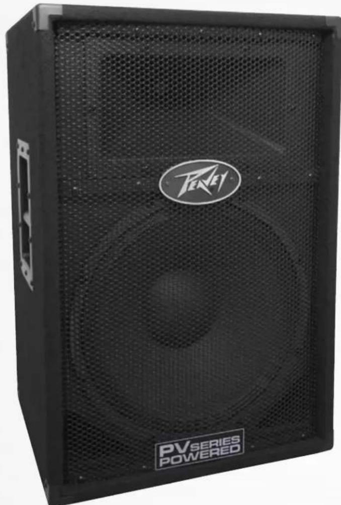
VOLTAGE SELECTOR SWITCH
The PV ® 1015D has a voltage selector switch to allow switching between an input power voltage range of 100VAC to 120VAC to a range from 220VAC to 240VAC, all at either 50 or 60 cycles per second (Hz). It should be preset to the proper voltage for your country out of the box.
Be sure to check the position of the voltage selector switch to see that it matches the power line voltage used locally. If it does not match, then to change the voltage to the correct one, following the steps outlined below.
Changing the Voltage Range of the PV 1015D
First, make sure the PV 1015D is disconnected from the power line, and that the power switch (3) is in the OFF position.
Second, loosen the screws holding the clear switch protector on the voltage selector switch (1) just enough to allow removal of the clear switch protector. The screws DO NOT need to be unscrewed very far.
Remove the clear plastic protector from the voltage selector switch.
Next, using a small flat blade screwdriver, push the red selector switch slide plate to the other side from where it was. The voltage that is now visible on the red slide plate is the one you have selected.
Replace the clear plastic protector underneath the two loosened screws, and tighten one down while holding the clear plastic protector in place. Tighten the other screw down, and make sure both screws are tight.
The fuse should be changed to the correct amperage rating. For an input power voltage range of 100VAC to 120VAC, use a 6.3 amp rated, 250V 5 x 20 mm cartridge type time-delay fuse, which conforms to the international fuse classification T6.3AL. For an input power voltage range of 220VAC to 240VAC, use a 3.15 amp rated, 250V 5 x 20 mm cartridge type time-delay fuse, which conforms to the international fuse classification T3.15AL.
The IEC power cord that is correct for your locale can now be plugged into the IEC receptacle (2), and the Power switch (3) activated to turn on the powered PV ® 1015D speaker system.
IEC POWER CORD CONNECTION
This receptacle is for the IEC line cord (normally supplied with the correct pins and wiring for your locale) that provides AC power to the unit.
Please read this guide carefully to ensure your personal safety as well as the safety of your equipment.
Never break off the ground pin on any equipment. It is provided for your safety. If the outlet used does not have a ground pin, a suitable grounding adapter should be used and the third wire should be grounded properly. To prevent the risk of shock or fire hazard, always be sure that the mixer and all other associated equipment are properly grounded.
FUSE
The unit is AC power line fuse protected from overloads and fault conditions with a slow-blow 5 x 20mm 250V fuse. This fuse is located within the cap of the fuse enclosure just to the left of the ON/OFF switch. If the fuse fails, THE FUSE MUST BE REPLACED WITH THE SAME TYPE AND VALUE IN ORDER TO AVOID DAMAGE TO THE EQUIPMENT AND TO PREVENT VOIDING THE WARRANTY!
The fuse in the PV 1015D can be replaced with a time-delay type 5 x 20 mm size 250V rated fuse.
For 100-120VAC operation, a fuse rated at 6.3 amps should be used. In the USA, types GDC, GMC, 215, 218, and 477 cartridge-style 5 x 20 mm size fuses with a 6.3 amp 250V rating can be used.
For 220-240VAC operation, a fuse rated at 3.15 amps and 250V should be used, which conforms to the international fuse classification T3.15AL.
If the unit continues to blow replacement fuses, do not keep replacing them, it should be taken to a qualified service center for repair.
To replace the fuse, be sure to remove the IEC power cord from the IEC socket (2).
2
2a
Remove the cap to the fuse enclosure (2a), using a flat-blade screwdriver tip inserted into the fuse cap slot. Push the cap in and turn the cap counterclockwise and pull the cap out. The blown fuse should come out with the cap. Remove the blown fuse and replace it with the proper type per instructions previously supplied. Then, once the new fuse has been put in place, re-insert the fuse enclosure cap, push in and turn the cap clockwise, and make sure it is fully seated. Before re-attaching the IEC power cord to the IEC socket, make sure the Power switch is in the OFF position, so that intermittent contact of the IEC cord while it is being connected will not unduly stress the amplifier or the fuse. Now re-attach the IEC power cord, and you can then use the Power switch to turn the unit on.

ON/OFF SWITCH
This rocker switch supplies AC power to the PV ® 1015D when switched to the ON position.

SPEAKER OUT JACK
This jack allows a full-range passive (unpowered) speaker to be connected to the PV 1015D internal power amp, as long as it has an impedance rating no lower than 8 ohms, and is of similar sensitivity as the PV 1015D speaker system. Ideally, this speaker would be the passive model PV 1015, however, other 8-ohm passive full-range speakers with a nominal sensitivity of around 95 dB can be used. This additional speaker system can help increase coverage of the venue. The volume level of this added speaker is controlled at the same time as the volume of the PV 1015D, thus the need to use a speaker system with a similar sensitivity.
It can also be used to drive an 8-ohm impedance, non-powered subwoofer with a built-in high-frequency roll-off, such as the PV 118 Sub.
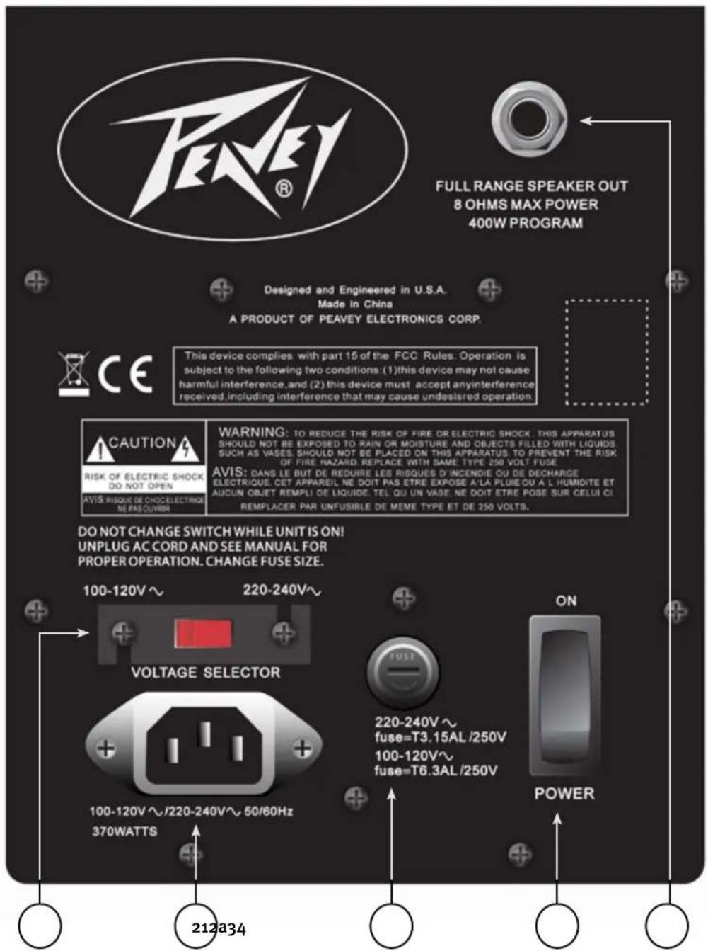
TOP PANEL

The line-level input is of the medium impedance type. Jack (5) is a combination female XLR and 1/4" TRS connector, and can be supplied with a balanced or unbalanced input signal.

LEVEL
Controls the gain (volume) of the Input (5) of the powered speaker system.

CONTOUR SWITCH
The Contour switch provides a mild boost at the frequency extremes, so that low-level playback can be more pleasing. Do not use the Contour switch when playing sound at loud levels, as the boost is not needed then.

LINK OUT
Link Out is a 1/4" pre-level send intended for the use of linking multiple PV 1015D enclosures in a line. In that case, the Link Out would connect to the 1/4" connections of the MIC/LINE (5) input of the next PV 1015D in the line of PV speakers. Individual speakers can be adjusted by their own Level control (6). This output can also be used to drive a nearby powered subwoofer, such as the PV 118D Sub. Set the PV 118D Sub level control to a level that matches that of the output of the PV 1015D.
POWER/CLIP LED
Illuminates GREEN when the electronics receive power (when the Power switch (3) is ON). Illuminates RED when amplifier clipping is occurring.
CAUTIONS
The unit must be disconnected from the AC power source before any work is done on it. Refer all servicing to qualified service personnel.
NOTE: This unit is not designed for overhead suspension!
The heat sink on the back plate can become hot to the touch. Do not block or cover the heat sink from ventilation.
DO NOT connect the inputs of the PV ® 1015D to the output of a power amplifier. The inputs are meant to be driven from a line-level strength signal.
When connecting a microphone to the system, be sure to keep the microphone away from the front of the speaker while setting the microphone level, or very loud feedback will occur! Damage to the system is likely if this occurs!
DO NOT remove the protective metal grille.
WARNING: The PV 1015D is very efficient and powerful! This sound system can permanently damage hearing! Use extreme care setting the overall maximum loudness!
The apparent sound level of the PV 1015D can be deceiving due to its clear, clean sound output. The lack of distortion or obvious distress can make the sound level seem much lower than it actually is. This system is capable of SPL in excess of 121 dB at 1 meter from the speaker!
Connecting AC Power To The PV1015D
The PV1015D comes with a 6-foot IEC connection AC power cord. If you are using an extension cord or power strip with this powered speaker, make sure it is of good quality and of a sufficient current capacity to maintain safety and maximize the power output capability of the PV 1015D. Do not connect any other device to the same extension cord that the PV 1015D is connected to.
Connecting a Signal to the PV 1015D
There are a variety of ways to input a signal to the PV 1015D.
The input jack (5) provides a balanced line-level input, allowing the use of a 1/4" phone plug, either a standard single-ended (tip-sleeve) plug or a balanced TRS (ring-tip-sleeve) type plug, OR a male XLR plug.
Do not connect cables to the jacks while the unit is ON and the Level is turned up!
While a standard shielded, single-ended 1/4" phone plug-equipped cable will work well and the balanced input circuitry of the input jack (5) will provide some interference rejection, a balanced cable using either the balanced TRS 1/4" phone plug or the XLR plug will provide superior interference rejection and performance. Sometimes, with difficult interference problems, it will be helpful to lift the shield ground on a balanced cable at the PV 1015D end. Check any input changes carefully, always turning the volume control down before plugging and unplugging cables, or making grounding changes.
Use of high-quality, premium cables is recommended for the PV 1015D, as these usually have better shielding and materials and will provide greater long-term reliability. It is usually a good idea to leave some slack at the input to the PV 1015D and also to tape down the cables or run them under a cable guard to avoid anyone tripping over them or pulling the PV 1015D over when stand mounted.
Level Control Adjustment
The PV 1015D is equipped with a level control (6) to facilitate use in many different applications. With the level control adjusted fully clockwise, gain is at maximum and the input sensitivity is 0.650 V RMS for full-rated output. When driving the PV 1015D from a mixer, it may be advantageous to reduce the input sensitivity by turning the level control to the one-third point or even less. The PV 1015D will now more closely match the sensitivity of a typical power amp.
If the mixing board indicates clipping of its output signals, then all of the PV 1015D power capability is not being utilized cleanly. Clipping the signal before it gets to the PV 1015D is not optimal. Reduce the mixer output level and turn up the level control on the PV 1015D.
The amplifier in the PV ® 1015D is equipped with DDT and an LED indicator to show that DDT has engaged. If the sound seems heavily compressed, check this indicator; if it is blinking RED more than occasionally, then the drive level from the mixer (or the level control on the PV 1015D) needs to be reduced.
When first turning on the sound system, switch on all upstream electronics first, then the PV 1015D with its level control fully counterclockwise (all the way down). Begin checking levels with the mixer output level controls all the way down, and bring them up slowly with the PV 1015D level control set to the desired setting (one-third of the way up is recommended as a starting point).
Using the SPEAKER OUT jack
The PV 1015D has a SPEAKER OUT, a 1/4" phone jack output on the rear panel. An external full-range passive speaker system (such as a PV 1015) can be connected to this jack, and powered by the internal amplifier. This external speaker must be an 8-ohm impedance or higher. YOU CANNOT CONNECT A 4-OHM SPEAKER TO THIS JACK. IT WILL CAUSE THE AMPLIFIER TO SHUT DOWN. Impedances lower than 8 ohms nominal are not allowed.
For best results when using this jack, the external speaker connected to it should be of a similar sensitivity to the PV 1015D, which has a sensitivity around 95 dB for 1w/1M. If the external speaker has a higher sensitivity, it will play louder than the PV 1015D, and make it hard to balance the sound in the room. If the external speaker has a lower sensitivity, then it will play softer than the PV 1015D does at any given Level setting.
Another consideration is to place the external speaker as far away as practical, to increase the overall coverage of the room, and to minimize the interference patterns that occur when two loudspeakers are near one another and radiating the same signal. Placing the external speaker at least 20-25 feet away from the PV 1015D would be a good practice. This would correspond to an example of having the PV 1015D on one side of a room, and the external speaker on the other side.
USE WITH A PASSIVE ADD-ON SUBWOOFER
Non-powered subwoofers that have a built-in high-frequency roll-off (often referred to as “add-on” subwoofers), can also be used with this output, as long as the nominal impedance is 8 ohms or above.
The PV 118 Sub is in this category, and can be used with this output jack. Normally, the closer to the PV 1015D the Sub is placed, the better it will work WITH the PV 1015D to increase bass output. Since the PV118 Sub has a built-in pole guide for placing a pole stand for the PV 1015D, this makes use of a PV 118 Sub a natural for use with the PV 1015D.
Use of the PV 1015D with a powered Subwoofer
Powered subwoofers often have a built-in electronic crossover to allow a high-pass filtered signal (lows rolled-off) to be sent to the upper range speaker. The PV 118D Sub is such a subwoofer. When using the PV 1015D with this type of powered subwoofer, first run the signal from the mixer or signal source to the powered sub input, then come out of the combo jack labeled "THRU/HPF" and send that signal to the PV 1015D input jack. On the PV 118D Sub, the button to the far left labeled THRU/HPF should be pushed in to engage the high-pass filter (HPF). On other powered subwoofers, if they have a similar high-pass filter function, then send the signal in and out of the subwoofer according to the manufacturer's instructions, which should be similar to the instructions as outlined above.
Use of the PV 1015D with a Speaker Stand
The PV1015D has a stand mount cup on the bottom so that the system can be stand mounted on a standard 1 3/8" (36mm) diameter stand pole.
When using stands or poles, be sure to follow these precautions:
A. Check the stand or pole specs to make sure that it can support the weight of the PV 1015D (56 lbs./25.4 kg), and observe all safety precautions stated by the stand manufacturer, including the maximum height the stand is rated for.
B. Always place the stand on a flat, level and stable surface, and be sure to fully extend the stand legs as per the stand manufacturer's instructions.
C. Try to make sure that the stand legs are oriented for the least danger of tripping to those in the vicinity of the stand. Never block a doorway or hallway with the legs of a stand.
D. Try to route cables so that people will not trip over them, or tip over the speaker. Use of duct tape, cable channels or guards, or other appropriate tie-down/cover up devices should be carefully considered and implemented.
E. When installing or un-installing the speaker on the stand, it is a good practice to have a helper if possible. It requires concentration to "thread the needle" and mate the stand cup to the stand pole while holding the PV 1015D speaker system at arm's length. It is also helpful if someone holds the speaker stand and pole down while the PV 1015D is removed from the stand pole, this prevents the PV 1015D from pulling the pole up with it.
F. When using stands outdoors, never attach banners or flags to the stands or the PV ® 1015D speaker system, as strong winds may cause the speaker to blow over. If there is a possibility of windy conditions, then it may be prudent to consider weighting or locking down the stand legs to prevent the PV ® 1015D speaker system from being blown over.
TROUBLESHOOTING
No Output at All
First, make sure the unit has AC power and is turned ON. Make sure the Power/Clip LED (9) is illuminated Green. If not, make certain the ON/OFF switch (3) is in the ON position and check the IEC power cord connection (2) by ensuring it is fully engaged and seated. Make certain the AC line cord is plugged into a working AC outlet. Finally, check the fuse (2a). (See the Rear Panel: Fuse section, for safety instructions.)
Once assured your unit is getting AC power, check that the PV 1015D is getting a signal. Temporarily disconnect the cable running to its inputs and connect it to some other device capable of reproducing the signal (i.e., a power amp and speaker). If this produces a signal, make sure that all Volume controls being used have been turned up to a satisfactory level (one-third to halfway).
If the PV 1015D has been subjected to direct sunlight or excessive heat, the built-in thermal protection may have been triggered. The power/clip LED will be illuminated RED if this is the case. If so, turn off the PV 1015D and let it cool for a sufficient amount of time.
If there is still no output, contact your authorized Peavey ® dealer or the Peavey International Service Center.
Hum or Buzz
If the PV 1015D is producing a hum or buzz, this can be AC outlet related. Try plugging the PV 1015D into a different AC outlet. Sometimes, if a different AC power circuit (breaker) is used for the mixer and the PV ® 1015D, it can cause hum problems.
Ensure that shielded cables have been used to route the signal to the PV 1015D enclosure's inputs. If speaker cables with 1/4" plugs are used as input cables instead of shielded cables, they will be prone to hum or buzz.
The third wire (ground plug) on the AC plug should NEVER be removed or broken off.
Hum may be ground loop-related. It may be helpful to lift the shield ground on a balanced cable at the PV 1015D end only by disconnecting the cable shield at the plug. Check any input changes carefully by first turning down the level control before plugging and unplugging cables, or changing the grounding.
Check to make sure light dimmers are not on the same circuit as the PV 1015D, the mixer or any source devices. If light dimmers are used, then it may be necessary to turn them full, ON or fully OFF to eliminate or reduce hum. This is a typical AC wiring/light dimmer interference problem, not a design flaw of the PV 1015D.
Distorted or Fuzzy Sound
First, ensure the mixer (signal source) is not clipping or being overdriven. Make sure the level control
(6) on the PV 1015D has not been set too low. Check that the input plugs are fully seated in the input jack (5) on the rear panel of the PV 1015D. Ensure that a power amp output has not been plugged into the input jack (5) of the PV 1015D. If an extension cord is being used to provide the AC power to the unit, ensure that it is of sufficient current capacity and that it is not also being used to supply power to any other device.
The PV 1015D has a Contour switch (7) to provide boost of the bass and treble for low playback levels. If excessive additional bass boost or high-frequency boost have been added externally to the PV ® 1015D while the Contour switch is engaged, it could cause premature overload at high SPL. Switch the Contour button OFF, which is the "out" position, and reduce the amount of any external EQ and see if that clears up the distortion.
Finally, realize that even though the PV 1015D is a powerful and high output unit, it does ultimately have limits, and you may need additional powered units (or a subwoofer) to provide enough sound output or coverage for your application. In this case, try turning the mixer levels down a little to see if that clears things up.
If, after checking all the things listed to check and anything else you can think of to check safely, and the system still exhibits problems, carefully note all conditions and check with your Peavey ® dealer for advice.
Care and Maintenance
Your PV ® 1015D is a sturdy and durable product and will provide years of reliable use if properly cared for. Use common sense and read the safety warnings to avoid hazardous operating conditions.
The unit must be disconnected from the AC power source before any work is done on it. Refer all servicing to qualified service personnel.
Sunlight/Heat
Avoid prolonged exposure to direct sunlight, as this may cause the unit to overheat and thermally shut off.
Excessively hot operating conditions can also cause a thermal shutdown.
Do not store in extremely hot or cold conditions or extremely high humidity. Always allow unit to come to room temperature before use.
Cleaning
Never clean the PV 1015D while plugged in or turned ON! When the unit has been fully disconnected from AC power sources, use a dry cloth or a plastic bristle brush to remove soil or other dirt. Never use strong solvents on the PV 1015D, as they could damage the cabinet. Do not allow ANY fluids to drip inside the PV 1015D.
ARCHITECTURAL AND ENGINEERING SPECIFICATIONS
The powered loudspeaker system shall have a frequency response from 63 Hz to 18 kHz. The peak SPL with inaudible distortion shall reach 121 dB with music as a source, when measured at a distance of 1M and driven to full output capacity. The system shall utilize a heavy-duty 15" Peavey ® Sheffield ® model woofer, and a PeaveyRX ™ 14 titanium diaphragm compression driver tweeter on a patented asymmetrical Quadratic Throat Waveguide ™ constant directivity horn. The nominal radiation geometry shall be 100° in the horizontal plane and 50° in the vertical plane. The vertical plane radiation geometry shall be asymmetrical, at +15, -35°.
The powered loudspeaker system shall have a medium impedance input connector consisting of one combo female XLR and 1/4" RTS phone jack on the rear panel. Output connections on the rear panel shall consist of a 1/4" phone jack providing link-out, which provides a pre-level control signal for the use of linking multiple PV 1015D enclosures in a line, and one 1/4" phone jack speaker output, 8-ohm minimum load. A level control will be located next to the input jack. Next to the level control, a Contour Switch push button will provide some bass and treble lift when engaged for improved listening at low levels.
The system power amplifier shall have an unfiltered frequency response of 20 Hz to 20 kHz which deviates no more than +0, -3 dB up to rated power, a damping factor greater than 400 @ 1 kHz into 8 ohms, hum and noise better than 90 dB below rated power, and typical THD and IMD of less than 0.5%. The amplifier shall be capable of 400W continuous output into a 4 ohm nominal load and shall incorporate DDT ™ compression.
The enclosure shall be constructed of MDF-type wood panels, and be covered in black carpet. A pair of metal handles shall be provided on the sides, and a stand mount adaptor on the bottom for speaker stand use. A black-coated perforated metal grille shall be provided for speaker component protection. The cabinet shall incorporate 4 rubber feet for floor standing use
The outside dimensions shall be 27.56" tall by 18.13" wide by 16.88" deep, and the weight shall be 56 lbs. Power requirements shall be a dual voltage range of: 100 to 120VAC, and 220 to 240VAC, 50 - 60 Hz, with a nominal power consumption of 370 watts. The voltage ranges shall be switch selectable on the rear panel. The loudspeaker system shall be called a Peavey model PV 1015D.
PEAVEY ® PV ® 1015D - SPECIFICATIONS
Frequency Range: 1 meter on-axis, swept-sine in 1/2 Space environment, -10 dB: 43 Hz to 21 kHz
Frequency Response: 1 meter on-axis, swept-sine in 1/2 Space environment 63 Hz to 18 kHz (±3 dB)
Sensitivity (1w/1m): 95 dB
Maximum Peak SPL: 121 dB
Transducer Compliment: Heavy-duty 15" Pro 15 woofer with 2 3/8" voice coil & 50 oz. Magnet. RX TM 14 1.4" titanium diaphragm dynamic compression driver, loaded on a Peavey exclusive 100 degree by 50 degree Quadratic Throat Waveguide.
Nominal Coverage Pattern: 100° horizontal X 50° vertical. Axis of the vertical main polar lobe is angled down 10°, resulting in the angular pattern with respect to straight ahead being +15, -35°
Electro-Acoustic Crossover Frequency: 2.8 kHz
Input Connections: One combo female XLR/1/4" phone jack providing balanced or unbalanced operation.
Enclosure Materials & Finish: Trapezoidal, black carpet covered 15mm MDF, black powder-coated full length perforated steel grille.
Mounting or Suspension: Steel 1 3/8" pole-mount cup for stand mounting, four rubber feet for floor use.
NOTE: This unit is not designed for overhead suspension!
Dimensions (H x W x D):
Front: 27.56in. X 18.13 in. x 16.88 in. 700 mm x 461 mm x 429 mm
Rear: 27.56in. x 15.38 in. x 16.88 in. 700 mm x 391 mm x 429 mm
Weight:
56 Lbs. (25.4 kg)
ELECTRONICS AND AMPLIFIER SPECIFICATIONS:
Power Amp Rating, Total Power Output:
800 watts peak available power. Continuous power 400 watts into 4 ohms @ less than 1% distortion
Electronic Input Impedance (Nominal): 2.7 k ohms balanced (XLR or 1/4"), 1.35 k ohms unbalanced 1/4".
Infrasonic Filter Protection: 24 dB/octave roll-off
Nominal Amplifier Frequency Response: +0, -3 dB from 20 Hz to 20 kHz Hum and Noise: Greater than 90 dB below rated power
DDT Dynamic Range: Greater than 14 dB
THD and IM: Typically less than 0.5 %
Damping Factor: Greater than 400 @ 1000 Hz, 8 Ohms
Power Requirements of Peavey PV®2015D System: Nominal 370 Watts, Voltage and Frequency Ranges: 100-120 VAC, and 220 - 240VAC, at 50-60 Hz
Fuse Type:
For 100-120 VAC USE: International fuse classification T6.3AL. In the USA, types GDC, GMC, 215, 218, and 477 cartridge-style 5 x 20 mm size fuses with a 6.3 amp 250V rating can be used.
For 220-240VAC USE: International fuse classification T3.15AL. This is a cartridge style 5 × 20 mm size time-delay fuse with a 3.15 amp 250V rating.

PV ® 1015D
1
VOLTAGE SELECTOR UMSCHALTER
A
COMMUTATEUR VOLTAGE SELECTOR
Dimensions (H x L x P) :
Avant : 27,56m. X 18.13 in. x 16.88 in.
700 mm x 461 mm x 429 mm
Arrière : 27,56m. x 15,38 in. x 16,88 in.
700 mm x 391 mm x 429 mm
Poids :
56 lbs. (25,4 kg)

INTERRUPTOR VOLTAGE SELECTOR
A
INTERRUTTORE VOLTAGE SELECTOR
A
VOLTAGE SELECTOR-OMKOPPLARE
IEC-NÄTSLADDSANSLUTNING

VOLTAGE SELECTOR -KYTKIN

CHAVE VOLTAGE SELECTOR


VOLTAGE SELECTOR 开关
Effective Date: 09/15/2010
What This Warranty Covers
Your Peavey Warranty covers defects in material and workmanship in Peavey products purchased and serviced in the U.S.A. and Canada.
What This Warranty Does Not Cover
The Warranty does not cover: (1) damage caused by accident, misuse, abuse, improper installation or operation, rental, product modification or neglect; (2) damage occurring during shipment; (3) damage caused by repair or service performed by persons not authorized by Peavey; (4) products on which the serial number has been altered, defaced or removed; (5) products not purchased from an Authorized Peavey Dealer.
Who This Warranty Protects
This Warranty protects only the original purchaser of the product.
How Long This Warranty Lasts
The Warranty begins on the date of purchase by the original retail purchaser. The duration of the Warranty is as follows:
| Product Category Duration | |
| Guitars/Basses, Amplifiers, Preamplifiers, Mixers, Electronic Crossovers and Equalizers 2 years *(+ 3 years) | |
| Drums 2 years *(+ 1 year) | |
| Enclosures 3 years *(+ 2 years) | |
| Digital Effect Devices and Keyboards and MIDI Controllers 1 years *(+ 1 year) | |
| Microphones 2 years | |
| Speaker Components 1 year(incl. Speakers, Baskets, Drivers, Diaphragm Replacement Kits and Passive Crossovers) | |
| Tubes and Meters | 90 Days |
| Cables Limited Lifetime | |
| AmpKit Link, Xport, Rockmaster Series, Strum'n Fun, RetroFire, GT & BT Series Amps | 1 year |
[* Denotes additional Warranty period applicable if optional Warranty Registration Card is completed and returned to Peavey by original retail purchaser within 90 days of purchase.]
What Peavey Will Do
We will repair or replace (at Peavey's discretion) products covered by Warranty at no charge for labor or materials. If the product or component must be shipped to Peavey for Warranty service, the consumer must pay initial shipping charges. If the repairs are covered by Warranty, Peavey will pay the return shipping charges.
How To Get Warranty Service
(1) Take the defective item and your sales receipt or other proof of date of purchase to your Authorized Peavey Dealer or Authorized Peavey Service Center.
OR
(2) Ship the defective item, prepaid, to Peavey Electronics Corporation, International Service Center, 412 Highway 11 & 80 East, Meridian, MS 39301. Include a detailed description of the problem, together with a copy of your sales receipt or other proof of date of purchase as evidence of Warranty coverage. Also provide a complete return address.
Limitation of Implied Warranties
ANY IMPLIED WARRANTIES, INCLUDING WARRANTIES OF MERCHANTABILITY AND FITNESS FOR A PARTICULAR PURPOSE, ARE LIMITED IN DURATION TO THE LENGTH OF THIS WARRANTY.
Some states do not allow limitations on how long an implied Warranty lasts, so the above limitation may not apply to you.
Exclusions of Damages
PEAVEY'S LIABILITY FOR ANY DEFECTIVE PRODUCT IS LIMITED TO THE REPAIR OR REPLACEMENT OF THE PRODUCT, AT PEAVEY'S OPTION. IF WE ELECT TO REPLACE THE PRODUCT, THE REPLACEMENT MAY BE A RECONDITIONED UNIT. PEAVEY SHALL NOT BE LIABLE FOR DAMAGES BASED ON INCONVENIENCE, LOSS OF USE, LOST PROFITS, LOST SAVINGS, DAMAGE TO ANY OTHER EQUIPMENT OR OTHER ITEMS AT THE SITE OF USE, OR ANY OTHER DAMAGES WHETHER INCIDENTAL, CONSEQUENTIAL OR OTHERWISE, EVEN IF PEAVEY HAS BEEN ADVISED OF THE POSSIBILITY OF SUCH DAMAGES.
Some states do not allow the exclusion or limitation of incidental or consequential damages, so the above limitation may not apply to you.
This Warranty gives you specific legal rights, and you may also have other rights which vary from state to state.
If you have any questions about this Warranty or services received or if you need assistance in locating an Authorized Service Center, please contact the Peavey International Service Center at (601) 483-5365.
Features and specifications are subject to change without notice.
Optional Product Extended Warranty Registration
Give us some information and put your extended warranty into effect!
Please take a few minutes to fill out this information/survey sheet to help us get to know and serve you better.
To save time, submit your warranty registration online at www.peavey.com/support/warrantyregistration
| First Name | Initial | Last Name |
| Street Address |
| City( ) | State/Province | Postal Code |
| Telephone Number( ) | E-mail Address- - |
| Fax Number | Date of Birth |
| Gender | □M | □F |
| Model | 8-Digit Serial Number |
| Date of Purchase | Price Paid |
3.
Name of store where purchased
| City | State |
- Top two (2) reasons why you purchased from this store/dealer:
| Availability of productFriend/Relative's recommendationStore credit cardKnowledgeable staffAvailability of lessonsTechnical instruction | Past favorable experienceBest priceAdvertised specialConvenient locationReceived as a giftOther____ |
- Where do you most often shop for music and sound products?
| □ Independent retailer | □ Newspaper ads |
| □ Mass market retailer | □ Internet/Web sites |
| □ Mail order magazines | □ Other ____ |
- What two (2) factors most influenced your purchase of this product?
| □ Peavey brand name | □ Product appearance |
| □ Craftsmanship | □ Durability |
| □ Features for price | □ Prior experience with Peavey |
| □ Bundled accessories | □ Packaging |
| □ Sound quality | □ Other ____ |
- How did you learn about this Peavey product? (select best answer)
| □ Magazine review | □ Teacher's recommendation |
| □ Newspaper review | □ Catalog or flyer |
| □ Radio advertisement | □ Saw in store |
| □ Advertised special | □ Use by professional |
| □ Friend/Relative's recommendation | □ Other ____ |
| □ Salesperson's recommendation |
- Which other brands/models did you consider?
| 9. How would you describe your level of musicianship/technical expertise? |
| ☐ Beginner - Never played or taken less than one (1) year of lessons |
| ☐ Intermediate - One (1) to five (5) years of lessons or playing |
| ☐ Advanced - More than five (5) years of lessons or playing; play professionally |
- Education: (select best answer)
| □ High school |
| □ Some college |
| □ Completed college |
| □ Graduate school |
- Which best describe your family income? (select best answer)
| □ Under 15,000 | □75,000 - 99,999 |
| □15,000 - 24,999 | □100,000 - 149,999 |
| □25,000 - 34,999 | □ Over -150,000 |
| □ 35,000 -49,999 | |
| □ 50,000 -74,999 |
- Which of the following is your primary source of information on musical products: (select best answer)
| □ Television | □ Mail order catalogs |
| □ Radio | □ Direct mail |
| □ Internet | □ Literature from manufacturer |
| □ Newspaper | □ Other ____ |
| □ Magazines |
- What is your main motivation for buying new equipment?
| ☐ Replacing old product | ☐ Impulse |
| ☐ Want new and leading edge equipment | ☐ Need for improved performance |
| ☐ New technology | |
| ☐ Fullfill a specific need | ☐ Availability of product |
| ☐ Supplement existing products | ☐ Other |
- Please list your three most frequently visited Web sites.
| 1. http:// |
| 2. http:// |
| 3. http:// |
- In your opinion, what could Peavey do to improve its products and/or service? Please use the space below to tell us your answer.
Meridian, Ms 39302-5108
P.O. Box 5108
Attn: Warranty Department
Peaey Electronics Corporation

Place Postage Here


- IMPORTANT SAFETY INSTRUCTIONS
- SAVE THESE INSTRUCTIONS!
- Class-D Powered Two-Way Sound Reinforcement Speaker System
- FEATURES
- Description
- Applications
- BOTTOM PANE
- I
- VOLTAGE SELECTOR SWITCH
- Changing the Voltage Range of the PV 1015D
- IEC POWER CORD CONNECTION
- FUSE
- 2
- 2a
- ON/OFF SWITCH
- SPEAKER OUT JACK
- TOP PANEL
- LEVEL
- CONTOUR SWITCH
- LINK OUT
- POWER/CLIP LED
- CAUTIONS
- Connecting AC Power To The PV1015D
- Connecting a Signal to the PV 1015D
- Do not connect cables to the jacks while the unit is ON and the Level is turned up!
- Level Control Adjustment
- Using the SPEAKER OUT jack
- USE WITH A PASSIVE ADD-ON SUBWOOFER
- Use of the PV 1015D with a powered Subwoofer
- Use of the PV 1015D with a Speaker Stand
- TROUBLESHOOTING
- No Output at All
- Hum or Buzz
- Distorted or Fuzzy Sound
- Care and Maintenance
- Sunlight/Heat
- Cleaning
- ARCHITECTURAL AND ENGINEERING SPECIFICATIONS
- PEAVEY ® PV ® 1015D - SPECIFICATIONS
- ELECTRONICS AND AMPLIFIER SPECIFICATIONS:
- PV ® 1015D
- 1
- VOLTAGE SELECTOR UMSCHALTER
- A
- COMMUTATEUR VOLTAGE SELECTOR
- INTERRUPTOR VOLTAGE SELECTOR
- INTERRUTTORE VOLTAGE SELECTOR
- VOLTAGE SELECTOR-OMKOPPLARE
- IEC-NÄTSLADDSANSLUTNING
- VOLTAGE SELECTOR -KYTKIN
- CHAVE VOLTAGE SELECTOR
- VOLTAGE SELECTOR 开关
- Optional Product Extended Warranty Registration
Brand : PEAVEY
Model : PV 1015D
Category : Loudspeaker