Sineax M561 - Measuring equipment Camille Bauer - Free user manual and instructions
Find the device manual for free Sineax M561 Camille Bauer in PDF.
| Product type | Programmable multiple measurement converter |
| Brand | Camille Bauer |
| Model | Sineax M561 (also M562 and M563) |
| Dimensions (L × H × D) | Approximately 112.5 × 114.1 × 69.1 mm (housing P20/105) |
| Mounting | On "top hat" rail (EN 50 022) 35×15 or 35×7.5 mm |
| Auxiliary supply | 24 – 60 V DC/AC or 85 – 230 V DC/AC (depending on version); consumption ≤ 5 W / 7 VA |
| Measurement inputs | Alternating current (up to 12 A continuous) and alternating voltage (up to 693 V between phases) |
| Analog outputs | 1 to 3 galvanically isolated outputs (current 1…20 mA or voltage 5…10 V) |
| Programming interface | RS 232 C (connector programmable via M560 software and PRKAB 560 cable) |
| Measured quantities | Current, voltage, active/reactive/apparent power, power factor, frequency, etc. |
| Accuracy class | 0.5 or 1.0 depending on quantity and range |
| Measurement cycle | Approximately 0.6 to 1.6 s (50 Hz) |
| Response time | 1 to 2 measurement cycles |
| Electrical safety | Protection class II (protective insulation); IP40; overvoltage category III up to 300 V |
| Operating temperature | -10 to +55 °C |
| Storage temperature | -40 to +85 °C |
| Relative humidity | ≤ 75% annual average |
| Maximum altitude | 2000 m |
| Maintenance | No maintenance necessary; servicing only by the manufacturer or authorized service |
| Supplied accessories | Programming cable (PRKAB 560) and M560 configuration software (optional) |
| Certifications | CSA (USA/Canada), FCC Class A, Canadian DOC |
Frequently Asked Questions - Sineax M561 Camille Bauer
User questions about Sineax M561 Camille Bauer
0 question about this device. Answer the ones you know or ask your own.
Ask a new question about this device
Download the instructions for your Measuring equipment in PDF format for free! Find your manual Sineax M561 - Camille Bauer and take your electronic device back in hand. On this page are published all the documents necessary for the use of your device. Sineax M561 by Camille Bauer.
USER MANUAL Sineax M561 Camille Bauer
Operating Instructions
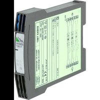
Programmable multi-transducer
SINEAX M561 / M562 / M563
text_image
15 16 17 18 19 20 - A + - B + - C + RS A P1 -115.47.115.47W -20.20mA B P2 -115.47.115.47W -20.20mA C P3 -115.47.115.47W -20.20mA 100V 2A 50Hz 3N - I1 U1 I1 I2 U2 I2 I3 U3 I3 SINEAX M563 Maf: 146A48 17777777 ACDC 08-250V 50kHz 7VA - ~ + N ACDC 08-250V 50kHz 7VA - ~ + 1 2 3 4 5 6 7 8 9 10 11 12 13 14M56x B d-f-e
143 579-06 08.14
Betriebsanleitung
Programmierbarer Multi-Messumformer
SINEAX M561 / M562 / M563 ......Seite 3
Mode d'emploi
Operating Instructions
Programmable multi-transducer
SINEAX M561 / M562 / M563 Page 23
The following symbols in the Operating Instructions indicate safety precautions which must be strictly observed:


The instruments must only be disposed of in the correct way!
Inhaltsverzeichnis
natural_image
Illustration of a hand holding a rectangular object with a downward arrow, next to a textured surface (no text or symbols)$$ X 0 \leq X \leq X 1 $$
$$ c = \frac {Y 1 - Y 0}{X 1 - X 0} \cdot \frac {X 2}{Y 2} \text { oder } c = 1 $$
$$ X 1 < X \leq X 2 $$
$$ c = \frac {1 - \frac {Y 1}{Y 2}}{1 - \frac {X 1}{X 2}} \text { oder } c = 1 $$
eingang (self powered):
≥ 24 - 60 V AC oder
85 - 230 V AC

bar
| Parameter | Value | |---|---| | U | 54.59 V | | Minimum | 54.55 | | Maximum | 58.02 | | Skala | 0.00 ... 57.74 | | I | 0.8387 A | | Minimum | 0.7099 | | Maximum | 0.6001 | | Skala | 0.0000 | | P | 45.67 W | | Minimum | 42.86 | | Maximum | 52.01 | | Skala | 0.00 ... 57.74 | The chart displays the voltage (U), current (I), and power (P) values for a microfluidic device in SIMRAX NOS. The data is presented in a grid format with grid cells for each parameter.natural_image
Diagram of a screwdriver holding a tool near a mechanical component (no text or symbols)Bild 7
Hersteller/ Manufacturer: Camille Bauer Metrawatt AG Switzerland
Anschrift / Address: Aargauerstrasse 7 CH-5610 Wohlen
The above mentioned product has been manufactured according to the regulations of the following European directives proven through compliance with the following standards:
Leiter Technik / Head of engineering

text_image
i.0. Brem J. Brem Qualitätsmanager / Quality managerSommaire
natural_image
Illustration of a hand holding a rectangular object with a downward arrow, next to a textured surface (no text or symbols)$$ X 0 \leq X \leq X 1 $$
$$ c = \frac {Y 1 - Y 0}{X 1 - X 0} \cdot \frac {X 2}{Y 2} \quad o u c = 1 $$
$$ X 1 < X \leq X 2 $$
$$ c = \frac {1 - \frac {Y 1}{Y 2}}{1 - \frac {X 1}{X 2}} \text { ou } c = 1 $$
IP 20, bornes de raccordement
natural_image
Diagram of a screwdriver holding a flat object with a tool, showing an upward arrow (no text or symbols present)Fig. 7
Hersteller/ Manufacturer: Camille Bauer Metrawatt AG Switzerland
Anschrift / Address: Aargauerstrasse 7
CH-5610 Wohlen
The above mentioned product has been manufactured according to the regulations of the following European directives proven through compliance with the following standards:
Leiter Technik / Head of engineering
- Read first and then.... 23
- Brief description ......23
- Mounting ......23
- Electrical connections .....23
- Commissioning 27
5.1 Technical data ......27
5.2 Programming the transducer ....30 - Reconfi guring the analog outputs .....30
- Notes of maintenance ....31
- Releasing the transducer ....31
- Dimensional drawing ....31
- Safety notes ....31
- Instrument admission ....31
- Declaration of conformity ....32
1. Read first and then ...

The proper and safe operation of the device assumes that the Operating Instructions are read and the safety warnings given in the sections
-
Mounting
-
Electrical connections
-
Commissioning
-
Safety notes
are observed.
The device should only be handled by appropriately trained personal who are familiar with it and authorized to work in electrical installations.
Unauthorized repair or alteration of the unit invalidates the warranty.
2. Brief description
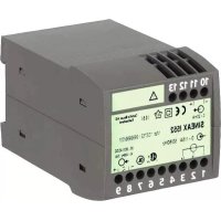
SINEAX M561 / M562 / M563 is a programmable transducer with a RS 232 C interface. It supervises any 1, 2 resp. 3 variables of an electrical power system simultaneously and generated 1, 2 resp. 3 electrically insulated analog output signals.
The transducers are also equipped with an RS 232 serial interface to which a PC with the corresponding software can be connected for programming or accessing and.
The usual methods of connection, the types of measured variables, their ratings, the transfer characteristic for each output etc. are the main parameters that can be programmed.
The ancillary functions include displaying, recording and evaluation of measurements on a PC, the simulation of the outputs for test purposes and a facility for printing nameplates.
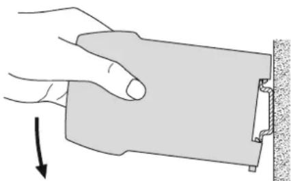
3. Mounting
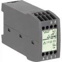
The transducer SINEAX M561 / M562 / M563 can be mounted on a top-hat rail.

Note “Environmental conditions” in Section “5.1 Technical data” when determining the place of installation!
Simply clip the device onto the top-hat rail (EN 50 022) (see Fig. 1).
natural_image
Illustration of a hand holding a rectangular object with a downward arrow, next to a textured surface (no text or symbols)Fig. 1. Mounting on top-hat rail 35 × 15 or 35 × 7.5 mm.
4. Electrical connections
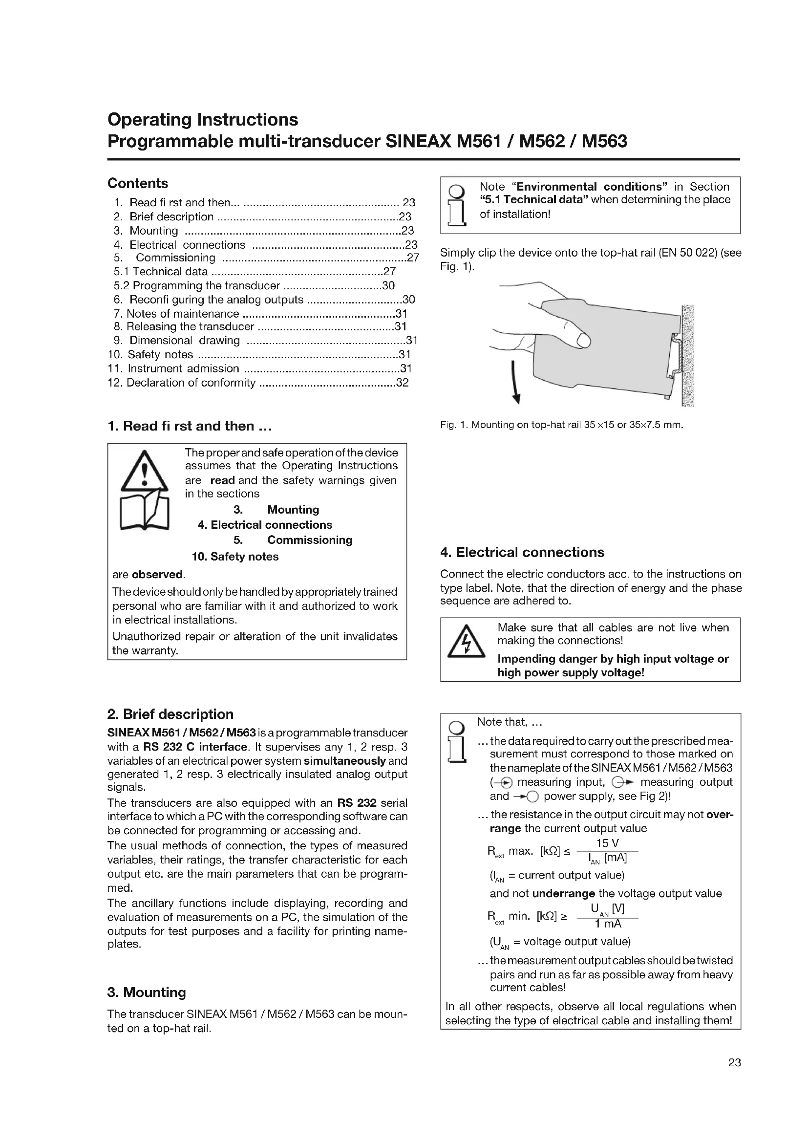
Connect the electric conductors acc. to the instructions on type label. Note, that the direction of energy and the phase sequence are adhered to.

Make sure that all cables are not live when making the connections!
Impending danger by high input voltage or high power supply voltage!

Note that, ...
... the data required to carry out the prescribed measurement must correspond to those marked on the nameplate of the SINEAX M561 / M562 / M563 (→ measuring input, → measuring output and → power supply, see Fig 2)!
... the resistance in the output circuit may not overrange the current output value
$$ R _ {\text { ext }} \max. [ k \Omega ] \leq \frac {1 5 \mathrm{V}}{I _ {\mathrm{AN}} [ \mathrm{mA} ]} $$
$$ \left(I _ {A N} = \text { current output value }\right) $$
and not underrange the voltage output value
$$ R _ {\text { ext }} \min. [ k \Omega ] \geq \frac {U _ {\mathrm{AN}} [ V ]}{1 \mathrm{mA}} $$
$$ \left(\mathrm{U} _ {\text { AN }} = \text { voltage output value }\right) $$
... the measurement output cables should be twisted pairs and run as far as possible away from heavy current cables!
In all other respects, observe all local regulations when selecting the type of electrical cable and installing them!
| Function | Connect. | |
| Measuring input AC current IL1 1/3 | ||
| -→IL2 4/6 | ||
| AC voltage UL1 2 | ||
| N | ||
| Outputs*) Analog | ||
| →A | 15 | |
| 16 | ||
| 17 | ||
| 18 | ||
| 19 | ||
| 20 | ||
| Power supply AC | 13 | |
| →DC | 14 | |
| + | ||
| RS 232 C interface | ||
*) M561: Output A
M562: Output A and B
M563: Output A, B and C
If power supply is taken from the measured voltage internal connections are as follow:
| Application (system) | Internal connection Terminal / System |
| Single-phase AC current | 2 / 11 (L1 - N) |
| 4-wire 3-phase symmetric load | 2 / 11 (L1 - N) |
| All other (apart from feature 9, lines E, F and J) | 2 / 5 (L1 - L2) |
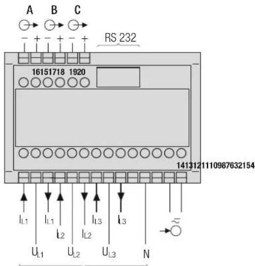
text_image
A B C RS 232 16151718 1920 1413121110987632154 IL1 IL1 IL2 IL2 IL3 IL3 UL1 UL2 UL3 N
Measuring inputs, acc. to measuring mode
| Measuring inputs | |||||
| System / Application | Terminals | ||||
| Single-phase AC system | 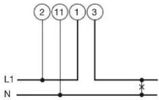 | 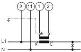 | 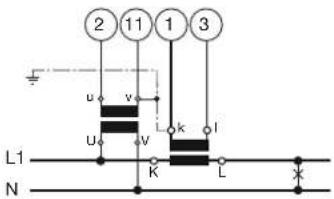 | ||
| 4-wire 3-phase symmetric load I: L1 | 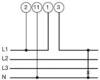 | 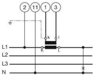 | 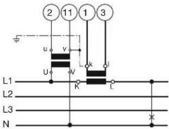 | ||
| Connect the voltage according to the following table for current measurement in L2 or L3: | |||||
| Current transf. | Terminals | 2 | 11 | ||
| L2 | 1 | 3 | L2 | N | |
| L3 | 1 | 3 | L3 | N | |
| Current transf. | Terminals | 2 | 11 | |
| L2 | 1 | 3 | L2 | N |
| L3 | 1 | 3 | L3 | N |
| Measuring inputs | |
| System /application | Terminals |
| 3-wire3-phasesymmetricloadI: L1 | 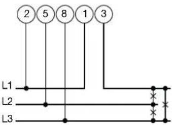 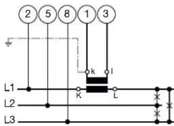 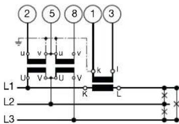 Connect the voltage according to the following table for current measurement in L2 or L3:Current transf. Terminals 2 5 8L2 1 3 L2 L3 L1L3 1 3 L3 L1 L2 Connect the voltage according to the following table for current measurement in L2 or L3:Current transf. Terminals 2 5 8L2 1 3 L2 L3 L1L3 1 3 L3 L1 L2 |
| 3-wire3-phasesymmetricloadPhase-shiftU: L1 - L2I: L1 | 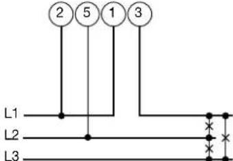 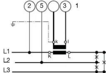 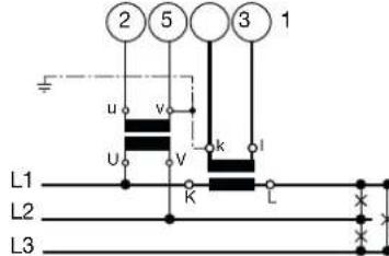 Connect the voltage according to the following table for current measurement in L2 or L3:Current transf. Terminals 2 5L2 1 3 L2 L3L3 1 3 L3 L1 Connect the voltage according to the following table for current measurement in L2 or L3:Current transf. Terminals 2 5L2 1 3 L2 L3L3 1 3 L3 L1 |
| 3-wire3-phasesymmetricloadPhase-shiftU: L3 - L1I: L1 | 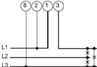 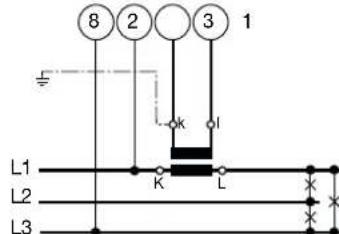 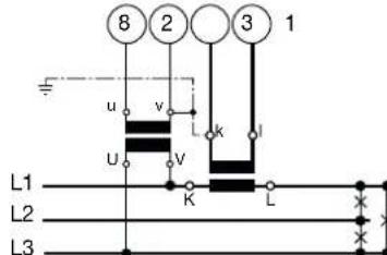 Connect the voltage according to the following table for current measurement in L2 or L3:Current transf. Terminals 8 2L2 1 3 L1 L2L3 1 3 L2 L3 Connect the voltage according to the following table for current measurement in L2 or L3:Current transf. Terminals 8 2L2 1 3 L1 L2L3 1 3 L2 L3 |
| Current transf. Terminals 2 5 8 | |||||
| L2 | 1 | 3 | L2 | L3 | |
| L3 | 1 | 3 | L3 | L1 | |
| Current transf. Terminals 2 5 | ||||
| L2 | 1 | 3 | L2 | |
| L3 | 1 | 3 | L3 | |
| Current transf. Terminals 8 2 | ||||
| L2 | 1 | 3 | L1 | |
| L3 | 1 | 3 | L2 | |
| Measuring inputs | |||||||
| System /application | Terminals | ||||||
| 3-wire3-phasesymmetricloadPhase-shiftU: L2 – L3I: L1 | 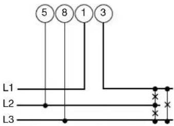 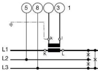 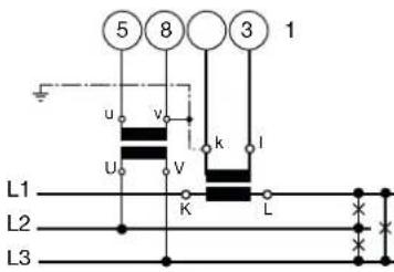 Connect the voltage according to the following tablefor current measurement in L2 or L3: Connect the voltage according to the following tablefor current measurement in L2 or L3: | ||||||
| 3-wire3-phaseasymmetricload | 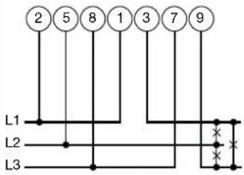 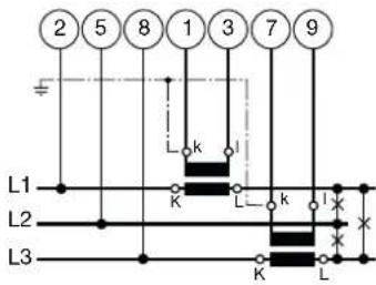 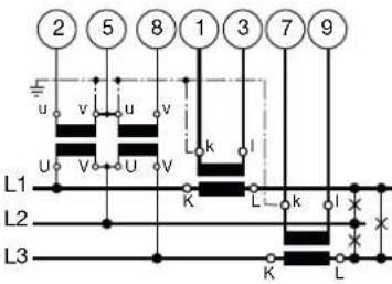 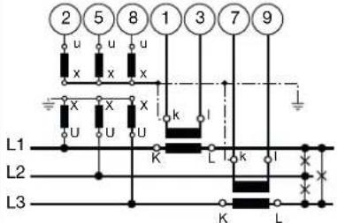 | ||||||
| 4-wire3-phaseasymmetricload | 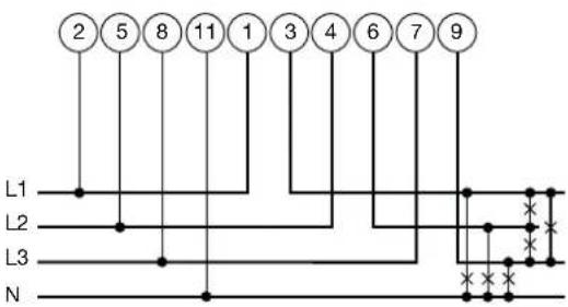 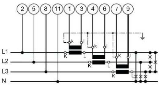 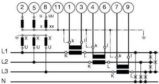 3 single-pole insulated voltage transformersin high-voltage system 3 single-pole insulated voltage transformersin high-voltage system | ||||||
| Measuring input | ||
| System / application | Terminals | |
| 4-wire3-phase asymmetric load,Open Y connection | 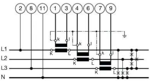 | 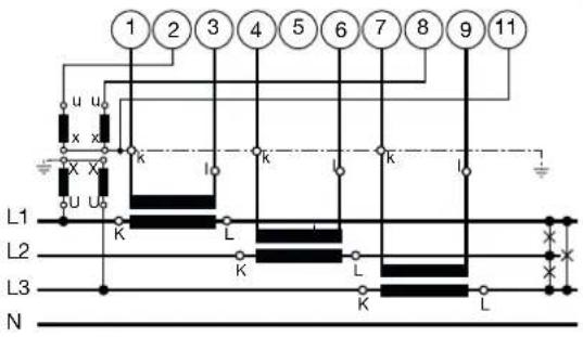 |
| Low-voltage system | 2 single-pole insulated voltage transformers in high-voltage system | |
5. Commissioning

Prior to starting, check that the connection data of the transducer agrees with the system data (see type label).
The power supply to the transducer can then be switched on and the signals applied to the measuring inputs.
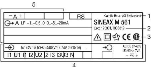
text_image
5 -A + RS Carnille Bauer AG Switzerland SINEAX M 561 Ord. 125831/1006319 3 A LF -1..-0.5..0 0..-5..-20mA 57.74V 1A 50Hz (440kV/57.74V 2500/1A) I1 U1 I1 I2 U2 2 I3 I3U3 N AC/DC 24-6CV 50/60Hz 7VA - ~ + 4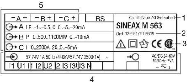
text_image
5 -A + -B + -C + RS A LF -1..-0.5..0 0..-5..-20mA B P 0..500..1100MW 0..-10mA C I 0..2500A 20..0..-5mA 57.74V 1A 50Hz (440kV/57.74V 2500/1A) - I1 U1 I1 I2 U2 I2 I3 I3U3 N Camille Bauer AG Switzerland SINEAX M 563 Ord: 125931/1006319 3.7 CE SE AC/DC 24-62V 50/60Hz 7VA - ~ + 4
Measuring input
Rated value of the input voltage Ur
Rated value of the input current Ir,
the figures in brackets are the ratios of the main, v.t's and
c.t's referred to Ur and Ir
Nominal frequency
System \~e.g. AC current

Measuring output, output signal

Power supply
1
Manufacturer
2
Works No.
3
Test and conformity mark
4
Terminals,
input quantities and power supply
5
Terminals, output quantities
Fig. 2. Declaration to type label.
5.1 Technical data
Symbols
| Symbols | Meaning |
| X | Measured variable |
| X0 Lower | limit of the measured variable |
| X1 Break | point of the measured variable |
| X2 Upper | limit of the measured variable |
| Y | Output variable |
| Y0 Lower | limit of the output variable |
| Y1 Break | point of the output variable |
| Y2 Upper | limit of the output variable (Hardware) |
| Y2 SW | Programmed upper limit of the output variable |
| U | Input voltage |
| Ur | Rated value of the input voltage |
| U 12 | Phase-to-phase voltage L1 – L2 |
| U 23 | Phase-to-phase voltage L2 – L3 |
| U 31 | Phase-to-phase voltage L3 – L1 |
| U1N | Phase-to-neutral voltage L1 – N |
| U2N | Phase-to-neutral voltage L2 – N |
| U3N | Phase-to-neutral voltage L3 – N |
| I | Input current |
| I1 AC current L1 | |
| I2 AC current L2 | |
| I3 AC current L3 | |
| Ir | Rated value of the input current |
| IM | Average value of the currents (I1 + I2 + I3) / 3 |
| IMS | Average value of the currents and sign of the active power (P) |
| IB | RMS value of the current with wire setting range (bimetal measuring function) |
| IBT | Response time for IB |
| BS | Slave pointer function for the measurement of the RMS value IB |
| BST Response time for BS | |
| Phase-shift between current and voltage | |
| F Frequency of the input variable | |
| Fn Rated frequency | |
| P Active power of the system P = P1 + P2 + P3 | |
| P1 Active powerphase 1 (phase-to-neutral L1 - N) | |
| P2 Active power phase 2 (phase-to-neutral L2 - N) | |
| P3 Active power phase (phase-to-neutral L3 - N) | |
| Q Reactive power of the system Q = Q1 + Q2 + Q3 | |
| Q1 Reactive power phase 1 (phase-to-neutral L1 - N) | |
| Q2 Reactive power phase 2 (phase-to-neutral L2 - N) | |
| Q3 Reactive power phase 3 (phase-to-neutral L3 - N) | |
| S Apparent power of the system | |
| S1 Apparent power phase 1 (phase-to-neutral L1 - N) | |
| S2 Apparent power phase 2 (phase-to-neutral L2 - N) | |
| S3 Apparent power phase 3 (phase-to-neutral L3 - N) | |
| Sr Rated value of the apparent power of the system | |
| PF | Active power factor = P/S |
| PF1 Active | power factor phase 1 P1/S1 |
| PF2 Active | power factor phase 2 P2/S2 |
| PF3 Active | power factor phase 3 P3/S3 |
| QF | Reactive power = Q/S |
| QF1 Reactive power factor 1 Q1/S1 | |
| QF2 Reactive power factor 2 Q2/S2 | |
| QF3 Reactive power factor 3 Q3/S3 | |
| LF Power factor of the system LF = sgnQ · (1 - |PF|) | |
| LF1 Power factor phase 1 sgnQ1 · (1 - |PF1|) | |
| LF2 Power factor phase 2 sgnQ2 · (1 - |PF2|) | |
| LF3 Power factor phase 3 sgnQ3 · (1 - |PF3|) | |
| c Factor for the intrinsic error | |
| R Output load | |
| Rn Rated burden | |
| H Power supply | |
| Hn Rated value of the power supply | |
| CT c.t. ratio | |
| VT v.t. ratio | |
Measuring input

Waveform:
Sinusoidal
Rated frequency:
50 or 60 Hz
Consumption [VA] (with
external power supply): Voltage circuit: U² / 400 kΩ
Current circuit: ≤ P · 0.01 Ω
Thermal rating of inputs
| Input variable | Number of inputs | Duration of overload | Interval between two overloads |
| Current circuit | 400 V single-phase AC system693 V three-phase system | ||
| 12 A — continu. — | |||
| 120 A 10 1 s | 100 s | ||
| 120 A 5 | 3 s | 5 min. | |
| 250 A 1 | 1 s | 1 hour | |
| Voltage circuit | |||
| 480 V/831 V ^1 | — contin. | — | |
| 600 V/1040 V ^1 | 10 10 s | 10 s | |
| 800 V/1386 V ^1 | 10 1 s | 10 s | |
^1 Maximum 264 V across the power supply when it is obtained from the measured variable with a power supply unit for 85 - 230 V DC/AC and maximum 69 V with a power supply unit for 24 - 60 V DC/AC.
Analog outputs
For the outputs A, B and C:
| Output variable Y | Impressed DC current | Impressed DC voltage |
| Full scale Y2 | 1 ≤ Y2 ≤ 20 mA | 5 ≤ Y2 ≤ 10 V |
| Limits of output signal for input overload and/or R = 0 | 1.2 · Y2 | 40 mA |
| 30 V | 1.2 Y2 | |
| Rated useful range of output lead | 0 ≤ 7.5 VY2 ≤ 15 VY2 | 22 mA ≤ 21 mA ≤∞ |
| AC component of output signal (peak-to-peak) | ≤ 0.01 Y2 | ≤ 0.01 Y2 |
The outputs A, B and C may be either short or open-circuited. They are electrically insulated from each other and from all other circuits (floating).
All the full-scale output values can be reduced subsequently using the programming software, but a supplementary error results.
System response
Accuracy class: (the reference value is the full-scale value Y2)
| Measured variable | Condition Accuracy | class1) |
| System:Active, reactive and apparent power | 0.5 ≤ X2/Sr ≤ 1.50.3 ≤ X2/Sr < 0.5 | 0.5 c1.0 c |
| Phase:Active, reactive and apparent power | 0.167 ≤ X2/Sr ≤ 0.50.1 ≤ X2/Sr < 0.167 | 0.5 c1.0 c |
| Power factor, active power and reactive power | 0.5Sr ≤ S ≤ 1.5 Sr,(X2 - X0) = 20.5Sr ≤ S ≤ 1.5 Sr,1 ≤ (X2 - X0) < 20.5Sr ≤ S ≤ 1.5 Sr,0.5 ≤ (X2 - X0) < 10.1Sr ≤ S < 0.5Sr,(X2 - X0) = 20.1Sr ≤ S < 0.5Sr,1 ≤ (X2 - X0) < 20.1Sr ≤ S < 0.5Sr,0.5 ≤ (X2 - X0) < 1 | 0.5 c1.0 c2.0 c1.0 c2.0 c4.0 c |
| AC voltage 0.1 Ur ≤ U ≤ 1.2 Ur 0.2 c | ||
| AC current/ current averages | 0.1 Ir ≤ I ≤ 1.2 Ir 0.2 c | |
| System frequency | 0.1 Ur ≤ U ≤ 1.2 Ur resp.0.1 Ir ≤ I ≤ 1.2 Ir | 0.15 + 0.03 c |
^1) Basic accuracy 1.0 c for applications with phase-shift
Duration of the
measurement cycle: Approx. 0.6 to 1.6 s at 50 Hz, depending on measured variable and programming
Response time: 1 ... 2 times the measurement cycle
Factor c (the highest value applies):
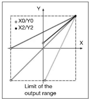
Linear characteristic:
$$ c = \frac {1 - \frac {Y 0}{Y 2}}{1 - \frac {X 0}{X 2}} \text { or } c = 1 $$
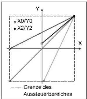
Bent characteristic: X0 ≤ X ≤ X1
$$ c = \frac {Y 1 - Y 0}{X 1 - X 0 Y 2} \cdot \frac {X 2}{\text { or } c = 1} $$
X1 < X ≤ X2
$$ c = \frac {1 - \frac {Y 1}{Y 2}}{1 - \frac {X 1}{X 2}} \text { or } c = 1 $$
text_image
X0/Y0 X2/Y2 Limit of the output rangeFig. 3. Examples of settings with linear characteristic.
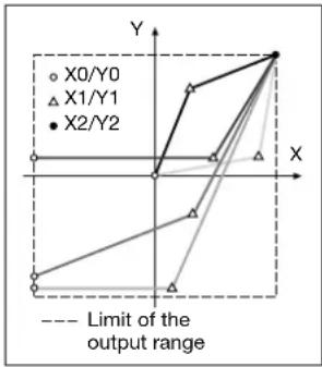
text_image
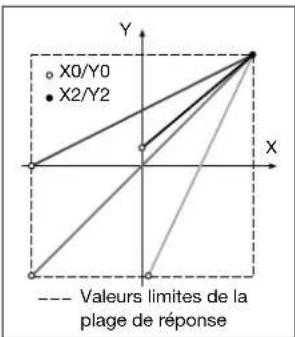
X0/Y0 X1/Y1 X2/Y2 Limit of the output rangeFig. 4. Examples of settings with bent characteristic.
(System response inversely confi gurable)
Infl uencing quantities and permissible variations
Acc. to IEC 688
Safety
Protection class: II (protection isolated, IEC 1010)
Enclosure protection: IP 40, housing (test wire, IEC 529) IP 20, terminals (test fi nger, IEC 529)
Pollution degree: 2
Installation category: III (with ≤ 300 V) II (with > 300 V)
Insulation test: Inputs: 300 V ^2) 600 V ^3) Power supply: 230 V Outputs: 40 V
Power supply →○
AC/DC power pack (DC or 50/60 Hz)
| Rated voltage | Tolerance |
| 24 - 60 V DC / AC | DC - 15 to + 33%AC ± 15% |
| 85 - 230 V DC / AC |
Power consumption: ≤ 5 W resp. ≤ 7 VA
Option
Power supply from measuring input
(self powered): ≥ 24 - 60 V AC or 85 - 230 V AC

Please note the max. and min. measuring input voltage!
| Type label inscription(* acc. to appli-cation N or U2) | Input voltage range= internal power supply range | Tolerance | Power supply connec-tion |
| Self powered by U1/(int. 24-60 V) | 24 - 60 V AC | ± 15% | Internal measuring input |
| Self powered by U1/(int. 85-230 V) | 85 - 230 V AC |
^2) Overvoltage category III
^3) Overvoltage category II
Programming connector on transducer
The programming connector on the transducer is connected by the programming cable PRKAB 560 to the RS-232 interface on the PC. The electrical insulation between the two is provided by the programming cable.
Ambient conditions
Nominal range of use
for temperature: 0...15...30...45 °C
(usage group II)
Operating temperature: -10 to +55 °C
Storage temperature: -40 to + 85 °C
Annual mean
relative humidity: ≤ 75%
Altitude: 2000 m max.
Indoor use statement
5.2 Programming the transducer

The transducers SINEAX M561 / M562 / M563 have an integrated RS 232 C interface (SCI).
The existing programmation can be matched conveniently to a changed situation and stored via the "Confi guration software for M 560" (Order number 146 557).
For this purpose, the RS 232 output of the transducer must be connected to a PC via the RS 232 C (SCI) programming cable (Order number 147 779 and 143 587) and the transducer must be supplied with power supply.
The confi guration software has an easy-to-operate, clear menu structure which allows for the following functions to be performed:
- Reading and displaying the programmed configuration of the transducer
- Clear presentation of the input and output parameters
• Transmission of changed programmation data to the transducer and for archiving of a file - Protection against unauthorized change of the programmation by entry of a password
- Conf i guration of all the usual methods of connection (types of power system)
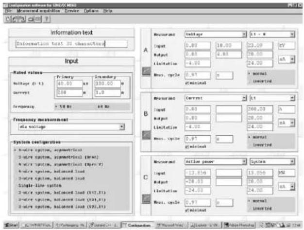
text_image
Configuration software for UNIX 906 File: Measured acquisition Service Options Help Information text Information text 3D characters Input Rated values Voltage (T) Primary Secondary Output 40.00 A 100.00 A Current 200 A 1.0 A Frequency 5 dB A B Hz Frequency measurement mA voltage System configurations a wire system, geometrical b wire system, geometrical (Wax) c wire system, geometrical (Wux-Y) d wire system, balanced load e wire system, balanced load Single-line system f wire system, balanced load (WZ,Y) g wire system, balanced load (WZ,Y) A B C A B C A B C A B C A B C A B C A B CFig. 5. Presentation of all programmation parameters in the main menu.
- Easy change of input and output parameters
WARNING: Watch for maximum input voltage on transducers with internal power supply connection from measuring input:
| Power supply | Power supply connection | Maximum input voltage across the power supply |
| 24 - 60 V AC Internal from measuring input | 69 V AC | |
| 85 - 230 V AC | 264 V AC | |
- Selection possible for frequency measurement via voltage or current
- Possibility to reset the slave pointer of the output quantity involved
- Parameter setting of outputs A to C (input of measured quantity, upper limits, limitation of upper limits and response time per output, possible up to max. 30 s)
• Graphics display of the set system behaviour of each output
line
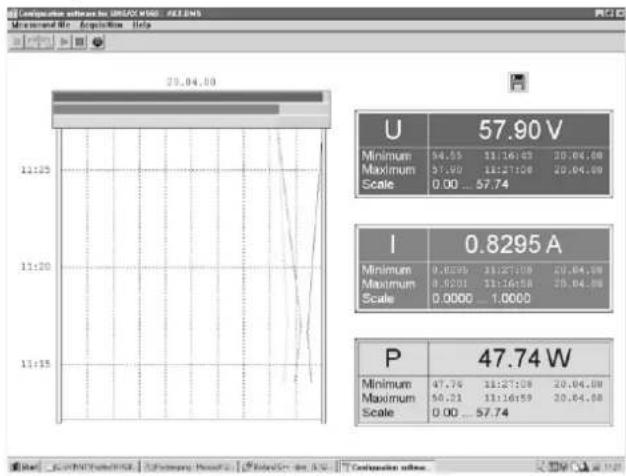
| Parameter | Value | |---|---| | U | 57.90 V | | Minimum | 94.55 | | Maximum | 57.90 | | Scale | 0.00 ... 57.74 | | I | 0.8295 A | | Minimum | 0.6395 | | Maximum | 0.6201 | | Scale | 0.0000 ... 1.0000 | | P | 47.74 W | | Minimum | 47.76 | | Maximum | 50.21 | | Scale | 0.00 ... 57.74 | The chart displays a single line graph with grid lines and a table below it showing 'U' and 'I' values for the time range from 29.04.00 to 11:15'. The 'P' value is explicitly labeled at the bottom.Fig. 6. Displaying, recording and evaluation of measurements.
Provision is also made for the following ancillary functions:
- Displaying, recording and evaluation of measurements on a PC
• The simulation of the outputs for test purposes - Printing of nameplates
6. Reconfiguring the analogue outputs
The alternative confi gurations for the analog outputs can be seen from Table 1.
Table 1:
| Action | Procedure |
| Change the current full-scale value from, for example, 20 mA to 10 mA(a hardware setting always thas to be made when changing from a lower to a higher value) | Reconfi gure the software,but do not change the hardware setting.Accuracy is reduced. |

Unauthorized repair of alteration of the unit invalidates the warranty!
7. Notes of maintenance
No maintenance is required.
8. Releasing the transducer
Release the transducer from a top-hat rail as shown in Fig. 7.
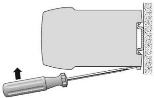
natural_image
Diagram of a screwdriver holding a flat object with a tool, showing an arrow indicating direction (no text or symbols present)Fig. 7
9. Dimensional drawing
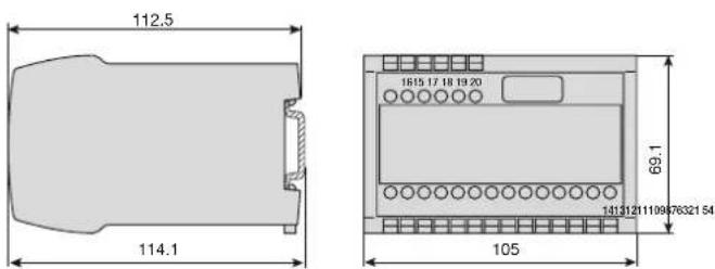
text_image
112.5 114.1 1815 17 18 19 20 69.1 105 1413121119947632154Fig. 8. Housing P20/105 clipped onto a top-hat rail (35 × 15 mm or 35×7.5 mm, acc. to EN 50 022.
10. Safety notes
● Before you start the device check for which power supply it is built.
- Verify that the connection leads are in good condition and that they are electrically dead while wiring the device.
- When it must be assumed that safe operation is no longer possible, take the device out of service (eventually disconnect the power supply and the input voltage!).
This can be assumed on principle when the device shows obvious signs of damage.
The device must only be used again after troubleshooting, repair and a final test of calibration and dielectric strength in our factory or by one of our service facilities.
- When opening the cover, live parts may be exposed.
Calibration, maintenance or repair with the device open and live must only be performed by a qualified person who understands the danger involved. Capacitors in the device may still be charged even though the device has been disconnected from all voltage sources.
11. Instrument admission

CSA approved for USA and Canada fi le-nr. 204 767
FCC Compliance and Canadian DOC Statement
This equipment has been tested and found to comply with the limits for a Class A digital device, pursuant to both part 15 of the FCC Rules and the radio interference regulations of the Canadian Department of Communications: These limits are designed to provide reasonable protection against harmful interference when the equipment is operated in a commercial environment. This equipment generates, uses and can radiate radio frequency energy and, if not installed and used in accordance with the instruction manual, may cause harmful interference to radio communications. Operation of this equipment in a residential area is like to cause harmful interference in which case the user will be required to correct the interference at his own expense.
12. Declaration of conformity

EG - KONFORMITÄTSERKLÄRUNG EC DECLARATION OF CONFORMITY

CAMILLE BAUER
Hersteller/ Manufacturer: Camille Bauer Metrawatt AG Switzerland
Anschrift / Address: Aargauerstrasse 7 CH-5610 Wohlen
Produktbezeichnung/ Programmierbarer Multi-Messumformer Product name: Programmable Multi-Transducers Typ / Type: SINEAX M561/M562/M563
The above mentioned product has been manufactured according to the regulations of the following European directives proven through compliance with the following standards:
Ort, Datum / Place, date:
Leiter Technik / Head of engineering
J. Brem

Qualitätsmanager / Quality manager