Sineax A210 - Measuring equipment Camille Bauer - Free user manual and instructions
Find the device manual for free Sineax A210 Camille Bauer in PDF.
| Product type | Multifunction power indicator for AC network analysis |
| Brand | Camille Bauer |
| Model | Sineax A210 |
| Category | Measuring equipment |
| Dimensions (front panel) | 96 x 96 mm |
| Depth | 107 mm (without extension module) |
| Panel cut-out | 92 x 92 mm |
| Weight | Approximately 0.5 kg |
| Power supply | 100-230 V AC/DC ±15% or 24-60 V AC/DC ±15% (85-125 V DC optional) |
| Power consumption | 3 VA (without extension module) |
| Voltage measurement inputs | Phase-to-phase: 500 V max, phase-to-neutral: 290 V max |
| Current measurement inputs | 5 A or 1 A nominal (10 A permanent max) |
| Nominal frequency | 50 / 60 Hz |
| Main functions | Measurement of voltages, currents, frequency, phase angle; calculation of active, reactive, apparent power; active and reactive energy; power factor; neutral current; 7-segment display; digital outputs S0 or alarm |
| Current/voltage accuracy | ±0,5% |
| Power accuracy | ±1,0% |
| Frequency accuracy | ±0,02 Hz (absolute) |
| Digital outputs | 2 passive optoelectronic outputs (S0 or alarm): Uext ≤ 40 V DC, IL ≤ 150 mA |
| Display | 3+1 digit 7-segment upper, 4 digit lower, units and symbols |
| Maintenance and cleaning | No maintenance required. Clean with a dry soft cloth |
| Safety | Protection class II, measurement category III, pollution degree 2, reference voltage 300 V |
| Operating conditions | Operating temperature -10 to +55 °C, storage -25 to +70 °C, max altitude 2000 m, humidity ≤75% |
| Connections | Screw terminals for voltage, current, power supply and outputs |
| Spare parts and repairability | No user-serviceable parts. Return to factory for repair |
| General information | Flush mounting, indoor use, programming via keys and locking bridge |
Frequently Asked Questions - Sineax A210 Camille Bauer
User questions about Sineax A210 Camille Bauer
0 question about this device. Answer the ones you know or ask your own.
Ask a new question about this device
Download the instructions for your Measuring equipment in PDF format for free! Find your manual Sineax A210 - Camille Bauer and take your electronic device back in hand. On this page are published all the documents necessary for the use of your device. Sineax A210 by Camille Bauer.
USER MANUAL Sineax A210 Camille Bauer
Operating Instructions Multifunctional Power Monitor
SINEAX A 210/A 220

Camille Bauer AG
Aargauerstrasse 7
CH-5610 Wohlen/Switzerland
Telefon +41 56 618 21 11
Telefax +41 56 618 21 21
info@camillebauer.com
www.camillebauer.com
text_image
231 234 232 231 234 232 A210 A220A 210/A 220 Bd-f-e 151 118-08 03.13


The instruments must only be disposed of in the correct way!
Safety notes
The installation and commissioning should only be carried out by trained personnel.
Check the following points before commissioning:
- that the maximum values for all the connections are not exceeded, see the "Technical data" section,
- that the connection wires are not damaged, and that they are not live during wiring,
- that the power flow direction, and the phase rotation are correct.
The instrument must be taken out of service if safe operation is no longer possible (e.g. visible damage). In this case, all the connections must be switched off. The instrument must be returned to the factory or to an authorized service dealer.
It is forbidden to open the housing and to make modifi cations to the instrument. The instrument is not equipped with an integrat- ed circuit breaker. During installation check that a labeled switch is installed and that it can easily be reached by the operators.
Unauthorized repair or alteration of the unit invalidates the warranty.
The A 210/A 220 are panel mounting instruments for monitoring AC systems with dimensions 96 x 96 mm (A 210) and 144 x 144 mm (A 220). The following measurements are acquired: voltages, currents, frequency, and phase angles in single phase or 3 phase systems. From these, the active power, reactive power, apparent power, active energy, reactive energy, and the power factor and the neutral current can be calculated. With the use of voltage and current transformers, the instrument can be used for measurements in medium and high voltage systems. The transformation ratios are confi gurable for the direct display of all measurements. The A 210/A 220 instrument is used as a display with two S0 pulse or limit value outputs.
Technical data
(for more detailed information please see data sheet, download under www.camillebauer.com)
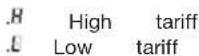
Measuring inputs →
Nominal frequency: 50, 60 Hz
Nominal input voltage: Phase-phase: 500 V
Phase - N: 290 V
Nominal input current: 5 A or 1 A
Continuous overload withstand
| 10 A at 346 V single phase AC system |
| 10 A at 600 V three phase system |
Short duration overload withstand
| Input variable | Number of applications | Duration of overload | Interval between two overloads |
| 577 V LN 10 1 s 10 s | |||
| 100 A 10 1 s 100 $ | |||
| 100 A 5 3 s 5 min |
Measuring ranges
U, I, S: ≤ 120% of nominal value
P, Q: ≤ ± 120% of nominal value
F: 45 to 65 Hz
cosφ: ±1
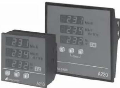
Pulse/Limit value outputs

Depending on the function selected, the two digital outputs can be used either as pulse outputs for active and reactive energy or as limit signals.
The outputs are passive, and are galvanically isolated from all the other circuits by opto-couplers. They are suitable to drive tariff devices (S0-standard DIN 43 864) or 24 V-relais.
U_ext ≤ 40 V DC (OFF: leakage current ≤ 0.1 mA)
I_L ≤ 150 mA (ON: terminal voltage ≤ 1.2 V)
text_image
SO2 Uext + - 20 RL 21 e.g. energy import t SO1 RL 22 e.g. limit value outputLimit value outputs
Any measured value can be allocated to the limit values.
Impulse outputs
Active and reactive energy impulses can be generated for driving electronic and electromechanical energy meters.
Power supply →○
DC, AC power pack 50 to 400 Hz
100 to 230 V AC/DC ±15% or 24 to 60 V AC/DC ±15%
(UL) 85 to 125 V DC
Power input: 3 VA (without extension module)

A marked and easily accessible current limiting switch has to be arranged in the vicinity of the device for turning off the power supply. Fusing should be 10 Amps or less and must be rated for the available voltage and fault current.
Reference conditions acc. to IEC 688 resp. EN 60 688
Sine 50 - 60 Hz, 15 - 30°, application group II
Measurement accuracy (related to nominal value)
| Current, voltage | ± 0.5% |
| Power | ± 1.0% |
| Power factor | ± 1.0% |
| Energy | ± 1.0% |
| Frequency | ± 0.02 Hz (abs.) |
Environmental conditions
| Operating temperature: | -10 to +55 °C |
| Storage temperature: | -25 to +70 °C |
| Relative humidity: ≤ 75% | |
| Altitude: | 2000 m max. |
| Indoor use statement |
Safety
Protection class: II (voltage inputs with protection impedances)
Measuring category: III
Pollution degree: 2
Measurement voltage: 300 V
Test voltage: Between current inputs, power supply, digital outputs, terminals of the plugged-in module: 3700 V / 50 Hz / 1 min.
At voltage inputs:
4.25 kV 1.2/50 μs
Module connections: The pin rail at the back is connected to the voltage inputs via a protection impedance. Only the permitted modules can be plugged-in!
Enclosure protection: IP 20
Note of maintenance
No maintenance is required.
Display
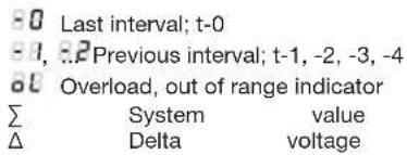
The measurement display is 3 digit resp. 4 digit (frequency) and right justified, with the exception of the energy values which are 8 digits. The left-hand 7-segment display is for the sign or an abbreviation.
Abbreviations:
| 8 | Maximal value |
| 9 | Minimal value |
| 10 | Average value |
| 11 | Max. average value |
| 12a | Minimal value for power factor; the worst out of the 3 values of P1, P2, or P3 is displayed |
| 13 | Neutral current |
| 14d | Inductive |
| CAP | Capacitive |
| 6ae | Incoming |
| 6AE | Outgoing |
| PGAE | Interval active power |
| 9GAE | Interval reactive power |
| 5GAE | Interval apparent power |
text_image
-0 Last interval; t-0 -1, 2.2 Previous interval; t-1, -2, -3, -4 60 Overload, out of range indicator Σ System value Δ Delta voltageEnergy meter
Current time t
Interval 0 Interval 1 Interval 2 Interval 3 Interval 4
t-0 t-1 t-2 t-3 t-4
Zero value suppression
PF resp. cosφ: Display ---, if Sx < 0.2% Snenn
Currents: Display 0, if lx < 0.1% Inenn
Commissioning
The multi-functional power monitor is made operational by switching on the power supply. The following appears sequentially on the display:
- Segment tests: all the segments of the displays and all the LEDs are lit for 2 s.
- Version of the software: e.g. A 210 1.04
- The 3 line voltages at switching on.
Loss of the power supply
All the values configured remain during a loss of the power supply. On reconnecting the power supply, the last mode selected is displayed.
Electrical connections
 | Safety DisconnectsThe mains supply power to the instrument must be installed downstream from a switched current limiting device.The circuit protection device should be 20 Amps or less, and must be rated for the available voltage and fault current; 5 Amp fuses are preferred. |
 | WARNINGAll mains supply power to the instrument must be installed downstream from a switched current limiting device.The circuit protection device should be 20 Amps or less, and must be rated for the available voltage and fault current; 5 Amps are preferred. |
| The national provisions (e.g. in Germany VDE 0100 “Conditions concerning the erection of heavy current facilities with rated voltages below 1000 V”) have to be observed in the installation and material selection of electric lines! | |
 | When using external PT’s or CT’s refer to the manufacturer’s information for connections for vol-tage and current monitoring. |
The electrical connections are identical for the SINEAX A 210 and A 220.
text_image
Measuring input, acc. to measuring mode I1 I2 I3 U1 U2 U3 N No. 1 1 2 3 4 5 6 7 8 9 11 I1 U1 I1 I2 U2 I2 I3 U3 I3 N UL 3-300V SA 50/6Hz CAT II EC: 3-500V200V SA 50/6Hz CAT III SINEAX A210 Net: 149783/123/1667/001 Camille Bauer AG 210-121200 Mon: 12/02 Switzerland S0 NL5xxxx 1 2 + LOCK 22 21 20 CE 14 15 DC=20VAC SU=125V DC 50-40Hz=2VA + - ~ + 1 2 + Jumper Pulse / Limit value outputs Power supply| Symbol | Meaning |
| Device may only be disposed of in a professional manner! | |
| Double insulation, device of protection class 2 | |
| CE conformity mark. The device fulfills the requirements of the applicable EC directives. | |
| Products with this mark comply with both the Canadian (CSA) and the American (UL) requirements | |
| Caution! General hazard point. Read the operating instructions. | |
| General symbol: Input | |
| General symbol: Output | |
| General symbol: Power supply | |
| CAT III | Measurement category CAT III for current and voltage inputs |
Connecting modes
| System/application | Terminals | |
| Single phaseAC system | 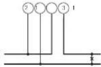 | 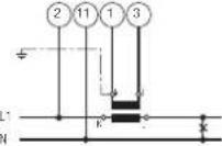 |
| L1N | L1 | |
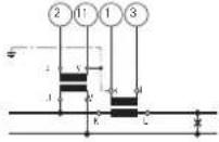 | ||
| 3wire3 phasesymmetricloadI: L1 | 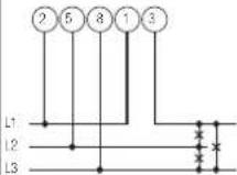 | 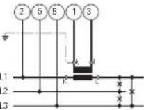 |
| L1L2L3 | 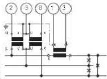 | |
| Connect the voltage according to thefollowing table for current measurement in L2or L3: | ||
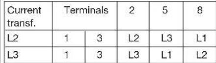 | ||
| 3 wire3 phaseasymmetricload | 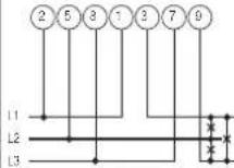 | 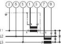 |
| Z5Z2 | 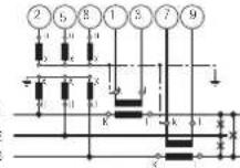 | |
| System/application | Terminals | ||||
| 4 wire3 phasesymmetricloadI: L14L68 | 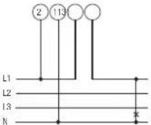 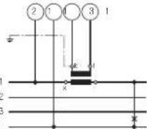  Connect the voltage according to the followingtable for current measurement in L2 or L3: Connect the voltage according to the followingtable for current measurement in L2 or L3: | ||||
| Current trans. | Terminals 2 11 | ||||
| L2 | 1 | 3 | |||
| L3 | 1 | 3 | |||
| 4 wire3 phaseasymmetricload4L68 | 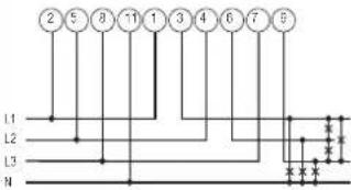 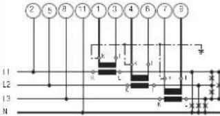 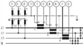 3 single-pole insulated voltage transformers inhigh-voltage system 3 single-pole insulated voltage transformers inhigh-voltage system | ||||
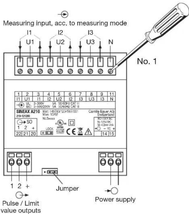
Display and operating
Display and operating are identical for the SINEAX A 210 and A 220
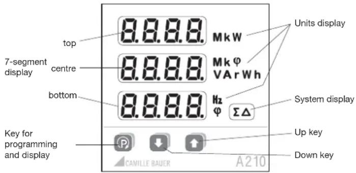
text_image
top 7-segment display centre bottom 8.8.8.8. MkW Mk φ VARWh Hz φ ΣΔ Units display System display Up key Down key Key for programming and display P ↓ ↑ CAMILLE BAUER A210Power factor cosφ 4 quadrant operation
| Available measurement data | Example display top | Example display centre | Example display bottom | Units display | System display |
| Phase voltages U1, U2, U3 230 231 229 V | |||||
| Maximum value U_1max , U_2max , U_3max . | 235 236 | 231 | V | ||
| Minimum value U_1min , U_2min , U_3min . | 227 226 | 225 | V | ||
| Delta voltages U12, U23, U31 400 402 398 V Δ | |||||
| Maximum values U_12max , U_23max , U_31max . | 405 406 | 403 | V | Δ | |
| Minimum values U_12min , U_23min , U_31min . | 395 397 | 396 | V | Δ | |
| Phase current I1, I2, I3 2.35 2.37 2.34 A | |||||
| Maximum values I_1max , I_2max , I_3max . | 2.39 2.40 | 2.38 | A | ||
| Average values I_1avg , I_2avg , I_3avg (bimetal -15 min.) | 2.04 2.05 | 2.07 | A | ||
| Max. average values I_1avgmax , I_2avgmax , I_3avgmax (slave pointer-15 min.) | 2.07 2.05 | 2.04 | A | ||
| Neutral current IN | 0.45 A | ||||
| Active powers P1, P2, P3 56.1 56.2 56.5 kW | |||||
| Maximum values P_1max , P_2max , P_3max . | 60.5 60 | 60.3 | kW | ||
| Active power system P 125 kW Σ | |||||
| Maximum value P_max . | 239 | kW | Σ | ||
| Reactive power Q1, Q2, Q3 1.24 1.23 1.22 Var | |||||
| Maximum values Q_1max , Q_2max , Q_3max . | 1.51 1.52 | 1.54 | VAr | ||
| Reactive power system Q | 1.54 VAr | Σ | |||
| Maximum value Q_max . | 2.31 | VAr | Σ | ||
| Apparent power S1, S2, S3 | 2.56 2.58 | 2.60 VA | |||
| Maximum values S_1max , S_2max , S_3max . | 3.43 3.44 | 3.67 | VA | ||
| Apparent power system S | 5.33 VA | ||||
| Maximum value S_max . | 6.23 VA | Σ | |||
| Power factor PF1, cosφ | 0.87 | φ | |||
| Power factor PF2, cosφ | 0.88 | φ | |||
| Power factor PF3, cosφ | 0.89 | φ | |||
| Power factor system PF, cosφ | 0.88 | φ | Σ | ||
| Minimum value power factor inductive | 0.76 | φ | Σ | ||
| Minimum value power factor capacitive | 0.84 | φ | Σ | ||
| Frequency, F | 49.99 | Hz | |||
| Active energy incoming EP high tariff | 4589 | 2356 | kWh | Σ | |
| Active energy incoming EP low tariff *) 1234 | 5678 | kWh | Σ | ||
| Active energy outgoing EP high tariff | 4589 2356 | kWh | Σ | ||
| Active energy outgoing EP low tariff *) | 1234 5678 | kWh | Σ | ||
| Reactive energy inductive EQ high tariff | 9876 5432 | kVarh | Σ | ||
| Reactive energy inductive EQ low tariff *) | 1234 | 9876 | kVarh | Σ | |
| Reactive energy capacitive EQ high tariff | 9876 5432 | kVarh | Σ | ||
| Reactive energy capacitive EQ low tariff *) | 1234 | 9876 | kVarh | Σ | |
| 5 active power intervals Pint0, Pint1, ... | 234 kW Σ | ||||
| 5 reactive power intervals Qint0, Qint1, ... | 123 VAr | ||||
| 5 apparent power intervals Sint0, Sint1, ... | 10.1 VA | ||||
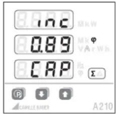
text_image
8.0°C 0.89 CAP A210System
text_image
1.09 0.95 1.09 A210Phase 1
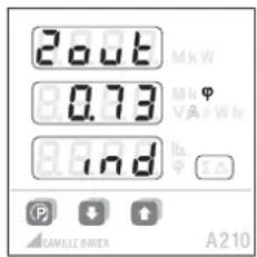
text_image
2.08 MkW 0.73 Mkφ VA Wlx 8.19d Hz Φ A210Phase 2
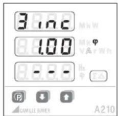
text_image
3.10°C 8.100 8.88 Hz A210Phase 3
*) Tariff switching via digital input only (optional extension module required)
Determination of measured quantities: The calculation of the measurements is made in accordance with DIN 40 110, with the exception of the reactive power. This is calculated by the SINEAX A 210/A 220 as a signed value.
Transducers and displays can possibly display different values for the reactive power in the same power system.
The reason is the different calculation methods.
Display levels
Within a level (1, 2, 3 ...) you can change the 3 displays to the next mode (a, b, c, ...) with the Ⓞ key. From the last mode, the display changes to mode a again.
Change to the next level with the ↑ and ↓ keys.
4 wire asymmetric load
| [IMAGE] | |||||||
| a | b | c | d | e | f | ||
 [GSGS] [GSGS] | 1 | U1U2U3 | U1max.U2max.U3max. | U1min.U2min.U3min. | U12U23U31 | U12max.U23max.U31max. | U12min.U23min.U31min. |
| 2 | I1I2I3 | I1max.I2max.I3max. | I1avgI2avgI3avg | I1avgmax.I2avgmax.I3avgmax. | IN IN | max. | |
| 3 | P1P2P3 | P1max.P2max.P3max. | P | Pmax. | |||
| 4 | Q1Q2Q3 | Q1max.Q2max.Q3max. | Q | Qmax. | |||
| 5 | S1S2S3 | S1max.S2max.S3max. | S | Smax. | |||
| 6 | PF1 PF2 PF3 PF PF | minind | PFmincap | ||||
| 7 | F | ||||||
| 8 | EP inc HT ^1 | EP inc LT ^2 | EP out HT ^1 | EP out LT ^2 | |||
| 9 | EQ ind HT ^1 | EQ ind LT ^2 | EQ cap HT ^1 | EQ cap LT ^2 | |||
| 10 | PQPF | PSF | |||||
| 11 | Pint0 Pint1 | Pint2 Pint3 | Pint4 | ||||
| 12 | Qint0 Qint1 | Qint2 Qint3 | Qint4 | ||||
| 13 | Sint0 Sint1 | Sint2 Sint3 | Sint4 | ||||
3 wire asymmetric load
| [IMAGE] | ||||||
| a | b | c | d | e | ||
  | 1 | U12U23U31 | U12max.U23max.U31max. | U12min.U23min.U31min. | ||
| 2 | I1I2I3 | I1max.I2max.I3max. | I1avgI2avgI3avg | I1avgmax.I2avgmax.I3avgmax. | ||
| 3 | P P | max. | ||||
| 4 | Q Q | max. | ||||
| 5 | S S | max. | ||||
| 6 | P F P | Finind | PFmincap | |||
| 7 | F | |||||
| 8 | EP inc HT ^1 | EP inc LT ^2 | EP out HT ^1 | EP out LT ^2 | ||
| 9 | EQ ind HT ^1 | EQ ind LT ^2 | EQ cap HT ^1 | EQ cap LT ^2 | ||
| 10 | PQPF | PSF | ||||
| 11 Pint0 Pint1 Pint2 Pint3 Pint4 | ||||||
| 12 Qint0 Qint1 Qint2 Qint3 Qint4 | ||||||
| 13 Sint0 Sint1 Sint2 Sint3 Sint4 | ||||||
Single-phase, 3 wire symmetric load, 4 wire symmetric load
| [IMAGE] | ||||||
| a | b | c | d | e | ||
 | 1 | U U | max. | U_min . | ||
| 2 | I I | max. | I_avg | I_avgmax . | ||
| 3 | P P | max. | ||||
| 4 | Q Q | max. | ||||
| 5 | S S | max. | ||||
| 6 | P F P | F_minind | PF_mincap | |||
| 7 | F | |||||
| [54WS] | 8 | EP inc HT^1 | EP inc NT^2 | EP out HT^1 | EP out NT^2 | |
| 9 | EQ ind HT^1 | EQ ind NT^2 | EQ cap HT^1 | EQ cap NT^2 | ||
| 10 | PQPF | PSF | ||||
| 11 | Pint0 Pint1 Pint2 Pint3 Pint4 | |||||
| 12 | Qint0 Qint1 Qint2 Qint3 Qint4 | |||||
| 13 | Sint0 Sint1 Sint2 Sint3 Sint4 | |||||
Operating
Brightness
13 levels: continuous pressing of the ↓ key (darker), or the ↑ key (brighter).
Delete / Clear
To delete the min. or max. values, or the energy values of the displayed measurements, press the keys at the same time.
Locking
The reset function for the energy meters can be locked by setting the jumper at the rear of the instrument to the position LOCK.
Programming
All parameters may be displayed at any time. For modifications the jumper on the backside of the device must be removed (not on position LOCK).
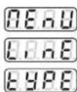
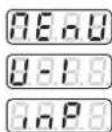
The following table shows all parameters with their adjustable ranges or possible selections respectively. The black numbers give a cross-reference to the appropriate diagram position on page 30.
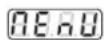
Starting at the measurands display by pressing the key 📄 you may change to the menu level.
Afterwards you can select the desired menu item by pressing the key Ⓓ shortly.
Use ↓ to enter the level where the desired parameter is dis played.
Pressing Ⓓ shortly will force the selectable element to flash.
The flashing content may be modified using the keys or
Press P for a longer time to leave the parameter or menu level.
All settings will remain non-volatile stored even in case of power-fail.
Hints:
First you have to set the system configuration and the transformer ratios because further measuring selections, alarm limit settings etc. will depend on them.
The programming may be modified via an optional extension module as well.
Locking the configuration
Place the jumper in the LOCK position.
The configuration of all parameters is disabled.

Factory Default
Brightness: (mid setting)
Limit value / S01: Off
Limit value / S02: Off
Transformer ratio: 1 : 1
Jumper: Not in the LOCK position
Connecting mode: 4 wire asymmetric load
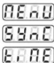
Synchronizing
interval: 15 min.
Parameters overview
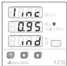
| No. | Topmost displayMiddle display | Undermost display(Selection, * = Default) | Meaning | Hints | ||
| 1 | System configuration | |||||
| 40.88.* | 4-line system, unbalanced load | (4 lines unbalanced) | ||||
| 30.88. | 3-line system, unbalanced load | (3 lines unbalanced) | ||||
| 40.68. | 4-line system, balanced load | (4 lines balanced) | ||||
| 30.68. | 3-line system, balanced load | (3 lines balanced) | ||||
| 40.88. | Single-line system | (1 line) | ||||
| 2 | 0.858. | 0.886 | Load type for energy recovery:Mathematical | 4 quadrant display, ind-cap-ind-cap | ||
| P.R.R.R. | E.E.E.O | Load type for energy recovery:Electrical | 4 quadrant display, ind-ind-cap-cap | |||
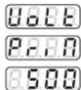
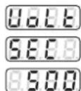
| 3 | 0.808. | 8.500 kV | Primary voltage of an externaltransformer on the voltage (line-to-linevoltage) | First you enter any 3-digit number followedby the appropriate power unit selection insteps of factor 10 | ||
| P.R.R.O | 100 V to 999 kV | |||||
| 4 | 0.808. | 8.500 v* | Secondary voltage of an externaltransformer on the voltage input(line-to-line voltage) | |||
| S.E.O.B. | 100 V to 999 V | |||||
| 5 | 0.808. | 8.500 A* | Primary current of an externaltransformer on the current input | |||
| P.R.R.O | 1.00 A to 999 kA | |||||
| 6 | 0.808. | 8.500 A* | Secondary current of an externaltransformer on the current input | |||
| S.E.O.B. | 0.1 A to 9,99 A | |||||
| No. | Undermost displayMiddle display | (Selection, * = default) | Meaning | Hints | ||
| 7 | 808.1/.2Node | Operating mode of both digital outputs "out.1" and "out.2" | (mode) | |||
| 8668.* | Output switched-off Simulation via interface module is still possible | |||||
| P005 | Energy pulse output The output generates energy pulses depending on the rate set under 12. The meter measurands to output may be selected under 11. | |||||
| A008 | Alarm output If the alarm limit is exceeded the output 9 will be active (current flows). If the measur- and is below limit 10 the output will be passive. The source of the monitored is selected under 8. | |||||
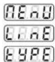
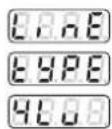
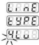
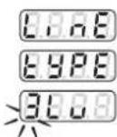
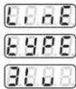
| 8 | 808.1/.2R582 | Alarm supervision source This selection is presented only if operating mode 7 is set to ALM previously | ||||
| Line Type | ||||||
| '1L', '3Lb', '4Lb' | '4Lu''3Lu' | |||||
| E888 | Frequency | ● | ● | ● | ||
| 8888 | Neutral current | ● | ||||
| S888 | Apparent power interval | ● | ● | ● | ||
| 9888 | Reactive power interval | ● | ● | ● | ||
| P888 | Active power interval | ● | ● | ● | ||
| P888 | Power factor (cos φ) | ● | ● | ○ | ||
| S888 | Apparent power | ● | ● | ○ | ||
| 9888 | Reactive power | ● | ● | ○ | ||
| P888 | Active power | ● | ● | ○ | ||
| U888 | Voltage | ● | ||||
| U088* | Line-neutral voltage | ○ | ||||
| U088 | Line-to-line voltage | ○ | ○ | |||
| 8880 | Average current (bimetal) | ● | ○ | ○ | ||
| 8888 | Phase current | ● | ○ | ○ | ||
| ○: 'A.on'= OR-operation of line-measurands'A.off'= AND-operation of line-measurands | ||||||
| 9 | 808.1/.2R888 | 8200 v* | Alarm limit for ON-state | The maximum values of the alarm limits depend on the possible measuring range (fixed by hardware), converted into possible primary values given by the selected system configuration and transformation ratios. | ||
| 10 | 808.1/.2R888 | 8220 v* | Alarm limit for OFF-state | |||
| No. | Undermost displayMiddle display | (Selection, * = default) | Meaning Hints | |||
| 11 | 808.3 / .2E.S.R.E | Source of energy meters for pulse output | ||||
| CAP.L | Reactive energy capacitive, low tariff | |||||
| CAP.H | Reactive energy capacitive, high tariff | |||||
| 8.8.d.L | Reactive energy inductive, low tariff | |||||
| 8.8.d.H | Reactive energy inductive, high tariff | |||||
| 8.8.E.L | Active energy outgoing, low tariff | (outgoing low tariff) | ||||
| 8.8.E.H | Active energy outgoing, high tariff | (outgoing high tariff) | ||||
| 8.8.E.L | Active energy incoming, low tariff | (incoming low tariff) | ||||
| 8.8.E.H * | Active energy incoming, high tariff | (incoming high tariff) | ||||
| 12 | 808.3 / .2E.R.E | 8.100 Mk*Wh1 to 5000 /Wh to GWh | Number of pulses per displayed energy unit. After entering a number from 1 to 5000 you may input the scaling: Basic unit (-), kilo (k), Mega (M) or Giga (Mk) | (energy rate) | ||
| 13 | 598.0E.R.O.E | 8.085 *1 to 60 min. | Time interval in minutes for the calculation of power intervals0 = Interval controlled via the bus | For external synchronization, the value displayed is not relevant | ||
Examples
Example 1: Programming the system configuration (3-line, unbalanced load)
- Press (P) > 2 s
- Press (present setting is displayed)
- Press (alterable parameter fl ashes)
- Press ↓ to select desired setting
- Press Ⓗ (takes over new setting). Display stops fl ashing.
- Press P > 2 s to return to display level
Example 2: Programming voltage transformer ratio and synchronization interval
- Press P > 2 s
- Press Ⓟ (transformer ratio menu)
- Press (present setting of primary voltage)
- Press Ⓟ (leftmost digit fl ashes)
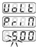
-
Press ↑ / ↓ until desired number appears
-
Press Ⓟ (middle digit fl ashes)
-
Press ↓ / ↑ until desired number appears
-
Press Ⓟ (rightmost digit fl ashes)
-
Press ↓ / ↑ until desired number appears
-
Press Ⓟ (decimal point fl ashes)
-
Press ↓ / t until the decimal point is on the desired position and the kilo/Mega display is correct
-
Press 📄 (takes over new value). The display stops fl ashing
-
Press ↓ (present setting of secondary voltage)
-
Programming procedure same as for primary voltage (1 to 12)
-
Press ↑ until the topmost display
- Press P three times
- Press ⬇ (present setting of synchronization interval in minutes)
- Press (P) (left digit fl ashes)

-
Press ↓ / ↑ until desired number appears
-
Press Ⓟ (right digit fl ashes)
-
Press ↓ / ↑ until desired number appears
-
Press 📄 (takes over new value). The display stops fl ashing
-
Press Ⓟ > 2 s (return to display level)
Konformitätserklärung / Certifi cat de conformité / Declaration of conformity
SINEAX A 210

EG - KONFORMITÄTSERKLÄRUNG EC DECLARATION OF CONFORMITY
CAMILLE BAUER
Hersteller: Camille Bauer AG Manufacturer: Switzerland
Anschritt / Aargauerstrasse 7 Address: CH-5610 Wohlen
The above mentioned product has been manufactured according to the regulations of the following European directives proven through compliance with the following standards:
| Nr. / No. | Richtlinie / Directive | |
| 2004/108/EC2004/108/EC | Elektronmagnetische Verträglichkeit - EMV RichtlinieElectromagnetic compatibility - EMC directive | |
| EMV /EMC | Fachgrundnorm /Generic Standard | Messverfahren /Measurement methods |
| Storaussendung /Emission | EN 51005-8-4 : 2007 | EN 55011 : 2007-A2:2007 |
| Storfestigkeit /Immunity | EN 51005-6-2 : 2005 | IEC 61000-4-2 : 1995+A1:1998+A2:2001IEC 61000-4-3 : 2006+A1:2007IEC 61000-4-4 : 2004IEC 61000-4-5 : 2005IEC 61000-4-6 : 2008IEC 61000-4-8 : 1993+A1:2000IEC 61000-4-11 : 2004 |
| Nr. / No. | Richtlinie / Directive | |
| 2008/95/EC2008/95/EC | Elektrische Betriebsmittel zur Verwendung innerhalb bestimmter Spannungsgrenzen - Niederspannungsrichlinie - CE-Kenzerzeichnung : 95 Electrical equipment for use within certain voltage limits - Low Voltage Diroslive - Attachment of CE marking : 95 | |
| EN/Norm/Standard | IEC/Norm/Standard | |
| EN 51010-1 : 2001 | IEC 61010-1 : 2001 | |
M. Ulrich J. Brem Letter: Technik / Head of Engineering Qualitalsmanager / Quality manager

Hersteller/ Camille Bauer AG Manufacturer: Switzerland
Anschritt / Address: Aargauerstrasse 7 CH-5610 Wohlen
The above mentioned product has been manufactured according to the regulations of the following European directives proven through compliance with the following standards:
If there is still a flashing 7-segment digit, decimal point or unit k : Back to 3.
- Change to the next parameter by pressing or and go back to 2.
or
go back to menu level with 🏠 and go on with 1.
Return to measurands display:
Press P for more than 2 seconds.
Anzeige-Ebene
Niveaux d'affichage
Display level
* with extension module
All dimensions in mm
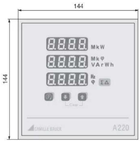
Masszeichnung / Croquis d'encombrement / Dimensional drawing SINEAX A 220
text_image
144 144 8.8.8.8 MkW 8.8.8.8 Mkφ VA rWh 8.8.8.8 Hz Φ ΣΔ ① Clear CAMILLE BAUER A220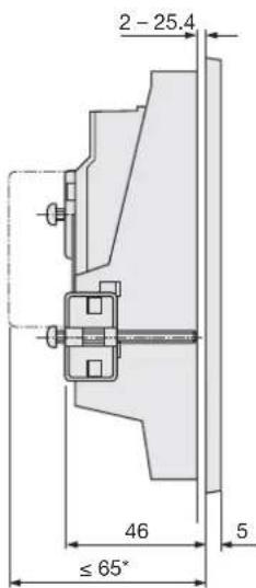
text_image
2 - 25.4 46 ≤ 65° 5* with extension module
Massangaben in mm
All dimensions in mm