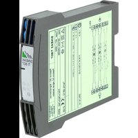
Sineax Ti807 - Measuring equipment Camille Bauer - Free user manual and instructions
Find the device manual for free Sineax Ti807 Camille Bauer in PDF.


| Product type | Passive galvanic isolator |
| Brand | Camille Bauer |
| Model | Sineax Ti807 |
| Input signal | 0...20 mA continuous (max. 50 mA) |
| Output signal | 0...20 mA or 0...10 V depending on variant |
| Number of channels | 2 or 3 galvanic isolation circuits |
| Power supply | No auxiliary power (passive) |
| Accuracy (current output) | Error < ±0.1% (20 mA, load 250 Ω) |
| Accuracy (voltage output) | Error < ±0.2% (10 V) |
| Operating temperature | -25 to +55 °C (standard), -20 to +55 °C (Ex version) |
| Storage temperature | -40 to +70 °C |
| Mounting | Symmetric 'top hat' rail (35×15 or 35×7.5 mm) or on wall |
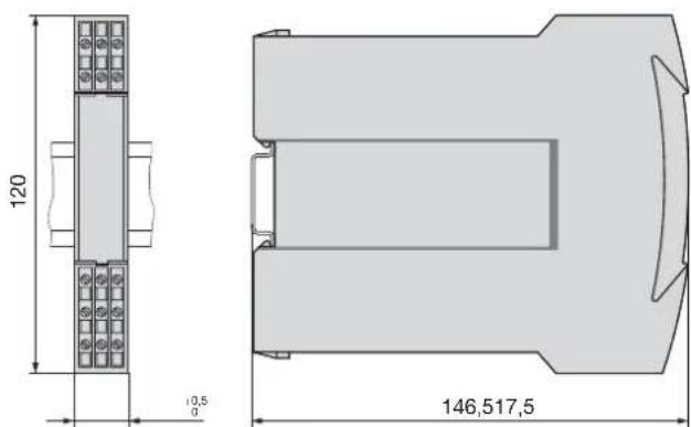
| Dimensions (approx.) | 146.5 × 120 × 17.5 mm (L × W × H) |
| Weight (estimated) | 200 g |
| Main functions | Galvanic isolation of DC current signals 0...20 mA and retransmission in current or voltage |
| Maintenance | No maintenance required |
| Repairability | Not user-repairable (warranty void if opened) |
| Safety | Observe safety instructions and Ex certificates for explosive versions |
| Available certifications | Ex version [EEx ib] IIC or [EEx ia] IIC |
Frequently Asked Questions - Sineax Ti807 Camille Bauer
User questions about Sineax Ti807 Camille Bauer
0 question about this device. Answer the ones you know or ask your own.
Ask a new question about this device
Download the instructions for your Measuring equipment in PDF format for free! Find your manual Sineax Ti807 - Camille Bauer and take your electronic device back in hand. On this page are published all the documents necessary for the use of your device. Sineax Ti807 by Camille Bauer.
USER MANUAL Sineax Ti807 Camille Bauer
Operating Instructions
Passive DC signal isolator SINEAX TI 807-1
TI 807-1 Bd-f-e 997 067-01 09.06
Camille Bauer AG
Aargauerstrasse 7
CH-5610 Wohlen/Switzerland
Telefon +41 56 618 21 11
Telefax +41 56 618 35 35
e-mail: info@camillebauer.com
http://www.camillebauer.com

CAMILLE BAUER
Betriebsanleitung
Passiver DC-Signaltrenner SINEAX TI 807-1 .... 3
Mode d'emploi
Operating Instructions
Passive DC signal isolator SINEAX TI 807-1 ......11
Safety precautions to be strictly observed are marked with following symbols in the Operating Instructions:





The instruments must only be disposed of in the correct way!
Inhaltsverzeichnis
signal UA : 0...10 V
Bild 4. Montage auf
Hutschiene 35×15
oder 35×7,5 mm.
Bild 11
- Mass-Skizzen
vibrations: 5 g, < 200 Hz,
Fig. 11
- Read first and then.... 11
- Scope of supply ....11
- Brief description ....11
- Specification and ordering information .....11
- Technical data ....11
- Exchanging frontplates .....12
- Mounting 12
- Electrical connections .....13
- Commissioning and maintenance .....14
- Releasing the signal isolator ....14
- Dimensional drawings ..... 14
- Declaration of conformity ....15
1. Read first and then ...

The proper and safe operation of the device assumes that the Operating Instructions are read carefully and the safety warnings given in the Sections
- Mounting
- Electrical connections.
The device should only be handled by appropriately trained personnel who are familiar with it and authorised to work in electrical installations.
Unauthorized repair or alteration of the unit invalidates the warranty!
2. Scope of supply
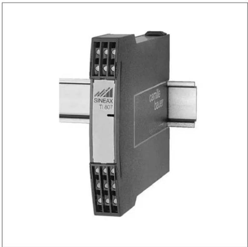
Signal isolator (Fig. 1)
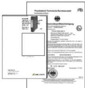
1 Operating Instructions (Fig. 2), in three languages: English, French and German
1 Ex approval (Fig. 2), only for Ex version devices
The signal isolator SINEAX TI 807 serves to electrically insulate two or three analog DC signals in the range 0...20 mA which depending on version is then converted to a current or voltage signal (0...20 mA or 0...10 V). It does not require a separate power supply.
- Specification and ordering information
| Order Code 807 - | |
| 1. Mechanical designHousing S17 1 | |
| 2. VersionStandard (non-Ex)Input and output signalsnon-intrinsically safe 1 | |
| [EEx ib] IIC,Input signals intrinsically safe 2 | |
| [EEx ia] IIC,Output signals intrinsically safe 6 | |
| 3. Number of isolationand transmission channels2 channels (interfaces) | 2 |
| 3 channels (interfaces) | 3 |
| 4. Output signals A1 and A2 or A1, A2 and A30 ... 20 mA | 0 |
| 0 ... 10 V, 2 channels | 2 |
| 0 ... 10 V, 3 channels | 3 |
| 5. Climatic ratingStandard climatic rating | 0 |
| Improved climatic rating | 1 |
5. Technical data
Input signal E
DC current signal IF : 0...20 mA
Max. permissible
current: 50 mA
Voltage limiter: Non-Ex version: 27 V, ±5% (with zener diode)
Ex version: 18 V, ±5%
Output signal A
(DC current or DC voltage)
DC current signal IA : 0...20 mA
Voltage drop Uv :
| < 2.8 V | for the standard (non-Ex) version |
| < 4.7 V | for Ex versions,(input signals “intrinsically safe”) |
| < 6.3 V | for Ex versions,(output signals “intrinsically safe”) |
Max. burden:
| 1000 Ω | for the standard (non-Ex) version |
| 500 Ω | for Ex versions,(input signals “intrinsically safe”) |
| 500 Ω | for Ex versions,(input signals “intrinsically safe”) |
Limit: Approx. 40 mA
Residual ripple: < 20 mV ss
Time constant: Approx. 3 ms
Response time 1
acc. to IEC 770: Approx. 15 ms
DC voltage signal UA : 0...10 V
Voltage drop Uv :
| < 2.8 V for | the standard (non-Ex) version |
| < 4.7 V for | Ex versions,(input signals “intrinsically safe”) |
| < 6.3 V for | Ex versions,(output signals “intrinsically safe”) |
Internal resistance: 500 Ω
Limit:
| < 26 V for | the standard (non-Ex) version |
| < 16 V for | Ex versions,(input signals “intrinsically safe”) |
| < 16 V for | Ex versions,(output signals “intrinsically safe”) |
Residual ripple: < 20 mV ss
Time constant: Approx. 3 ms
Response time 1
acc. to IEC 770: Approx. 15 ms
Accuracy data
Error limits: < ± 0.1%
(Reference value 20 mA,
including linearity error)
lt; ± 0.2 % 3
(Reference value 10 V,
including linearity error)
Ambient conditions
Operating temperature: -25 to +55 °C,
- 2 0 to + 5 5 ^ ° C
(Ex versions: input or output signals
"intrinsically safe")
Storage temperature: -40 to +70 °C
Annual mean
relative humidity: ≤ 75% standard climatic rating
≤ 95% improved climatic rating
Seismic test: 5 g, < 200 Hz,
2 h in each of 3 directions
Shock: 50 g,
10 shocks in each of 3 directions
Altitude: 2000 m max.
Indoor use statement!
This is the time which transpires before the output signal reaches the error limit of 1% for a step change of the input signal from 0 ∫90%.
2 With current signal and RA=250\ Ω .
3 With voltage signal
6. Exchanging frontplates
Apply gentle pressure to the transparent cover as shown in Fig. 3 (left) until it pops out on the opposite side. The label in the cover can be replaced and used for notes.
After replacing the label in the transparent cover, the transpa rent cover can be snapped into the front of the device again.
This is done by inserting it behind the edge at the bottom and pressing it gently down and to the rear with the finger until it snaps into place (right side of Fig. 3).
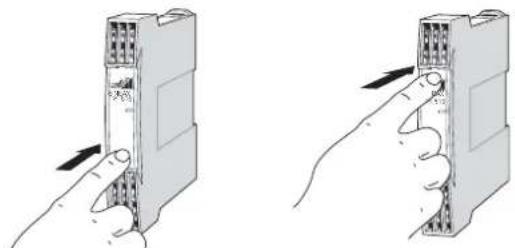
Fig. 3. Left: Removing the transparent cover Right: Inserting the transparent cover.
7. Mounting
The SINEAX TI 807 can be mounted either on a top-hat rail or directly onto a wall or mounting plate.
Make sure that the ambient temperature stays within the permissible limits:
- 25 and + 55 °C for standard instruments
-20 and +55 °C for instruments in Ex version!
7.1 Top-hat rail mounting
Simply clip the device onto the top-hat rail (EN 50 022) (see Fig. 4).
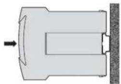
Fig. 4. Mounting on top-hat rail 35×15 or 35×7.5 mm.
7.2 Wall mounting
While pressing the latch (4) in the base of the device (Fig. 5, left) pull out the transmitter securing brackets (1). To return the brackets to their original positions, the latch (5) in the base of the device has to be depressed before applying pressure to the securing brackets (1) (see Fig. 5, right)
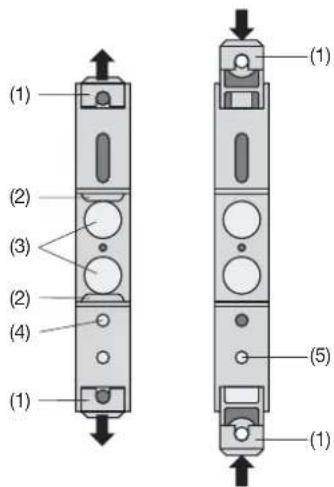
Fig. 5. Rear of device.
(1) Screw hole brackets
(2) Top-hat rail clip
(3) Rubber buffers
(4) Latch for pulling the screw hole brackets out
(5) Latch for pushing the screw hole brackets in
Drill 2 holes in the wall or panel as shown in the drilling pattern (Fig. 6). Now secure the signal isolator to the wall or panel using two 4 mm diameter screws.
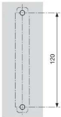
Fig. 6. Drilling pattern.
8. Electrical connections
The electrical connections are made to screw terminals which are easily accessible from the front of the signal isolator (see Figs. 7 to 10) and can accommodate wire gauges up to 2.5mm2 .

Make sure that the cables are not live when making the connections!

In the case of "intrinsically safe" explosion proof versions [EEx ib ] IIC or [EEx ia] IIC, the supplementary information given on the type examination certification, the EN 60 079-14 and also local regulations applicable to electrical installations in explosion hazard areas must be taken into account.


Note that, ...
... the required electrical insulation and transmission data agree with the data on the nameplate of the SINEAX TI 807 (-input signals and output signals)!
... in the case of a signal isolator with current outputs 0...20 mA, the total resistance of the external leads (receiver plus leads) does not exceed the maximum burden of 1000 Ω (non-Ex version) or 500 Ω (Ex version)! See “Output signal” in Section “5. Technical data”!
... in the case of a signal isolator with voltage output 0...10 V, the external receiver connected across the output has a sufficiently high internal resistance Ria in relation to the SINEAX TI 807 output impedance 600 Ω! See "Output signal" in Section "5. Technical data"!
The error due to Ria is:
F [%] = 5 0 0 [Ω] · 1 0 0Ri _ A [Ω]
... the input and output cables should be twisted pairs and run as far as possible away from heavy current cables!
Connect the input and output leads E1 ... E3 and A1 ... A3 according to Figures 7 to 10.
Signal isolator in housing S17 with two isolation and transmission channels
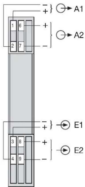
Fig 7.
Type 807-112..., standard (non-Ex) version and
Type 807-162..., Ex version (output signals A1 and A2 "intrinsically safe")
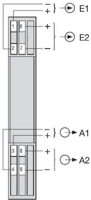
Fig. 8.
Type 807-122..., Ex version (input signals E1 and E2 "intrinsically safe")
Signal isolator in housing S17 with three isolation and transmission channels
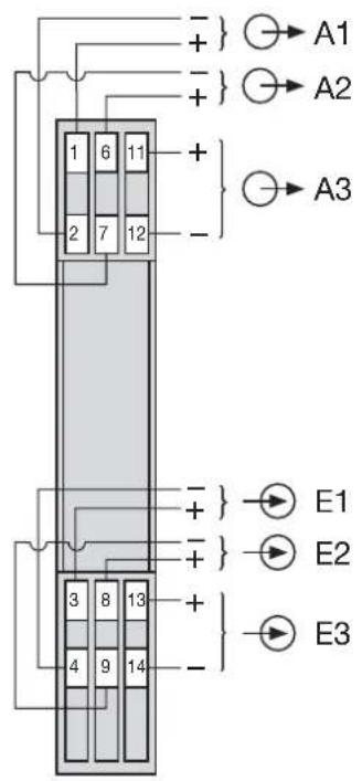
Fig. 9. Type 807-113..., standard (non-Ex) version and Type 807-163..., Ex version (output signals A1, A2 and A3 "intrinsically safe")
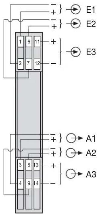
Fig. 10. Type 807-123..., Ex version (input signals E1, E2 and E2 "intrinsically safe")
9. Commissioning and maintenance
The device is in operation as soon as the input signals E1 ... E3 are connected.
The signal isolator requires no maintenance.
10. Releasing the signal isolator
Release the signal isolator from a top-hat rail as shown in Fig. 11.
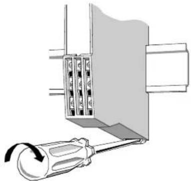
Fig. 11
- Dimensional drawings
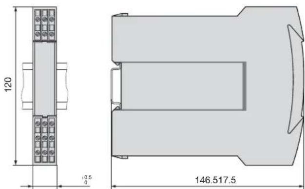
Fig. 12. SINEAX TI 807-1 (housing S17) clipped onto a top-hat rail (35×15 mm or 35×7.5 mm, acc. to EN 50 022).
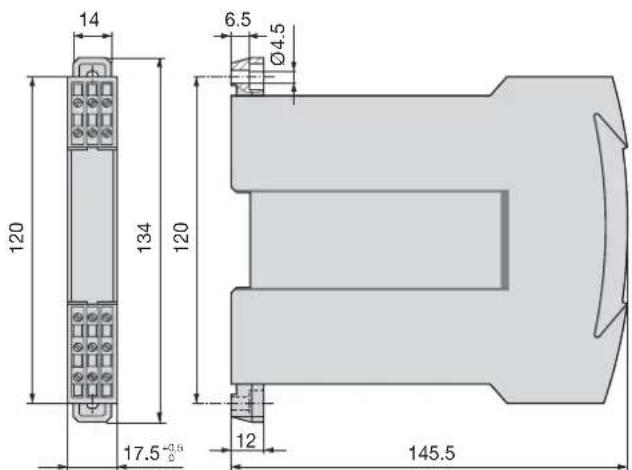
Fig. 13. SINEAX TI 807-1 (housing S17) with the screw hole mounting brackets pulled out.
12. Konformitätserklärung / Certificat de conformité / Declaration of conformity

EG - KONFORMITÄTSERKLÄRUNG DECLARATION OF CONFORMITY

Manufacturer: Switzerland
Address: CH-5610 Wohlen
Product name: Pasive DC signal isolator without power supply
Typ / Type: SINEAX TI 807 EX
The above mentioned product has been manufactured according to the regulations of the following European directives proven through compliance with the following standards:
The explosion protected variant of this product has been manufactured according the European directive 94/9.
Ort, Datum /
Place, date:
This declaration certifies compliance with the above mentioned directives but does not include a property assurance. The safety notes given in the product documentations, which are

- OPERATING INSTRUCTIONS
- PASSIVE DC SIGNAL ISOLATOR SINEAX TI 807-1
- BETRIEBSANLEITUNG
- PASSIVER DC-SIGNALTRENNER SINEAX TI 807-1 .... 3
- MODE D'EMPLOI
- PASSIVE DC SIGNAL ISOLATOR SINEAX TI 807-1 ......11
- INHALTSVERZEICHNIS
- READ FIRST AND THEN
- SCOPE OF SUPPLY
- SIGNAL ISOLATOR (FIG. 1)
- TECHNICAL DATA
- DC VOLTAGE SIGNAL UA : 0...10 V
- ACCURACY DATA
- AMBIENT CONDITIONS
- EXCHANGING FRONTPLATES
- MOUNTING
- 7.1 TOP-HAT RAIL MOUNTING
- 7.2 WALL MOUNTING
- ELECTRICAL CONNECTIONS
- SIGNAL ISOLATOR IN HOUSING S17 WITH THREE ISOLATION AND TRANSMISSION CHANNELS
- COMMISSIONING AND MAINTENANCE
- RELEASING THE SIGNAL ISOLATOR
- KONFORMITÄTSERKLÄRUNG / CERTIFICAT DE CONFORMITÉ / DECLARATION OF CONFORMITY
- EG - KONFORMITÄTSERKLÄRUNG DECLARATION OF CONFORMITY
Brand : Camille Bauer
Model : Sineax Ti807
Category : Measuring equipment