Sineax U539 - Measuring equipment Camille Bauer - Free user manual and instructions
Find the device manual for free Sineax U539 Camille Bauer in PDF.
| Product type | Measurement converter for AC voltage |
| Brand | Camille Bauer |
| Model | Sineax U539 |
| Category | Measuring equipment |
| Dimensions (L x H x D) | 112.5 x 69.1 x 114.1 mm |
| Weight | Approximately 0.2 kg |
| Auxiliary power supply | 230 V AC ±15 %, 50/60 Hz, approx. 3 VA (option: 24 V DC, 85–230 V DC/AC, etc.) |
| Measurement input | AC voltage 0–50 to 0–600 V, 50/60 Hz |
| Measurement output | DC current 0–20 mA (or live-zero 4–20 mA) or DC voltage 0–10 V |
| Accuracy | Class 0.5 (according to EN 60 688) |
| Response time | < 300 ms |
| Operating temperature | -10 to +55 °C |
| Storage temperature | -40 to +70 °C |
| Average annual relative humidity | ≤ 75 % |
| Maximum altitude | 2000 m |
| Overvoltage category | III (≤ 300 V), II (> 300 V) |
| Degree of pollution | 2 |
| Mounting | DIN rail (EN 50 022) 35 x 15 or 35 x 7.5 mm |
| Connection | Screw terminals (diagram according to nameplate) |
| Main functions | Conversion of a sinusoidal AC voltage into a proportional DC current or DC voltage |
| Maintenance and cleaning | No maintenance required |
| Safety | Follow the instructions in the manual; disconnect power before connection |
| Spare parts and repairability | Parts available from the manufacturer; unauthorized intervention voids the warranty |
| General information | Certified German Lloyd, CSA (USA/Canada), FCC Class A |
Frequently Asked Questions - Sineax U539 Camille Bauer
User questions about Sineax U539 Camille Bauer
0 question about this device. Answer the ones you know or ask your own.
Ask a new question about this device
Download the instructions for your Measuring equipment in PDF format for free! Find your manual Sineax U539 - Camille Bauer and take your electronic device back in hand. On this page are published all the documents necessary for the use of your device. Sineax U539 by Camille Bauer.
USER MANUAL Sineax U539 Camille Bauer
Operating Instructions
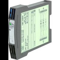
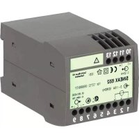
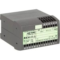
Transducer for AC voltage SINEAX U 539
text_image
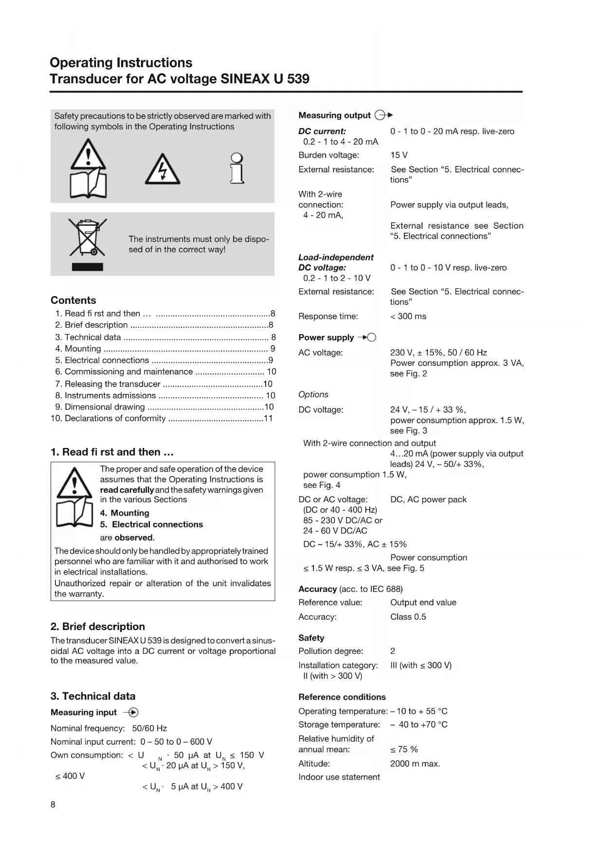
5 6 7 8 +1 Camille Bauer AG Switzerland 0-20mA SINEAX U539 Ord: 123 / 123456 / 123 / 123 0-100V 230V AC 50/60Hz 50/60Hz 3VA 1 2 3 4U 539 B d-f-e 136 475-05 02.14
(AC): 230 V, ± 15%, 50 / 60 Hz
natural_image
Illustration of a hand holding a rectangular object with a curved edge and a downward arrow indicating rotation (no text or symbols)natural_image
Diagram of a screwdriver inserted into a mechanical component, showing tool path and force direction (no text or symbols)Bild 7
Tension continue (CC): 24 V, -15 / + 33 %,
Tension continue (CC)
ou tension alternative
(CA):
natural_image
Illustration of a hand holding a rectangular object with a downward arrow, next to a vertical panel (no text or symbols)natural_image
Diagram of a screwdriver inserted into a mechanical component, showing tool path and force direction (no text or symbols)Fig. 7
Safety precautions to be strictly observed are marked with following symbols in the Operating Instructions


The instruments must only be disposed of in the correct way!
Contents
- Read first and then ... 8
- Brief description ....8
- Technical data 8
- Mounting 9
- Electrical connections .....9
- Commissioning and maintenance 10
- Releasing the transducer ....10
- Instruments admissions .... 10
- Dimensional drawing .....10
- Declarations of conformity ....11
1. Read first and then ...

The proper and safe operation of the device assumes that the Operating Instructions is read carefully and the safety warnings given in the various Sections
4. Mounting
- Electrical connections are observed.
The device should only be handled by appropriately trained personnel who are familiar with it and authorised to work in electrical installations.
Unauthorized repair or alteration of the unit invalidates the warranty.
2. Brief description
The transducer SINEAX U 539 is designed to convert a sinusoidal AC voltage into a DC current or voltage proportional to the measured value.
3. Technical data
Measuring input

Nominal frequency: 50/60 Hz
Nominal input current: 0 - 50 to 0 - 600 V
$$ \begin{array}{l} < U _ {N} \cdot 2 0 \mu A \text { at } U _ {N} > 1 5 0 V, \ \leq 4 0 0 \mathrm{V} \ < U _ {N} \cdot 5 \mu A \text { at } U _ {N} > 4 0 0 V \ \end{array} $$
Own consumption: < U N · 50 μA at U N ≤ 150 V
Measuring output
DC current: 0 - 1 to 0 - 20 mA resp. live-zero 0.2 - 1 to 4 - 20 mA
Burden voltage: 15 V
External resistance: See Section "5. Electrical connections"
With 2-wire connection: Power supply via output leads, 4 - 20 mA,
External resistance see Section "5. Electrical connections"
Load-independent
DC voltage: 0 - 1 to 0 - 10 V resp. live-zero 0.2 - 1 to 2 - 10 V
External resistance: See Section "5. Electrical connections"
Response time: < 300 ms
Power supply →○
AC voltage: 230 V, ± 15%, 50 / 60 Hz Power consumption approx. 3 VA, see Fig. 2
Options
DC voltage: 24 V, -15 / +33 %, power consumption approx. 1.5 W, see Fig. 3
With 2-wire connection and output 4...20 mA (power supply via output leads) 24 V, -50/+33%,
power consumption 1.5 W, see Fig. 4
DC or AC voltage: DC, AC power pack
(DC or 40 - 400 Hz)
85 - 230 V DC/AC or
24 - 60 V DC/AC
DC - 15/+ 33%, AC ± 15%
Power consumption
≤ 1.5 W resp. ≤ 3 VA, see Fig. 5
Accuracy (acc. to IEC 688)
Reference value: Output end value
Accuracy: Class 0.5
Safety
Pollution degree: 2
Installation category: III (with ≤ 300 V)
II (with > 300 V)
Reference conditions
Operating temperature: -10 to +55 °C
Storage temperature: - 40 to +70 °C
Relative humidity of annual mean: ≤ 75 %
Altitude: 2000 m max.
Indoor use statement
4. Mounting
The SINEAX U 539 can be mounted on a top-hat rail.

Note "Environmental conditions" in Section "3. Technical data" when determining the place of installation!
Simply clip the device onto the top-hat rail (EN 50 022) (see Fig. 1).
natural_image
Illustration of a hand holding a rectangular object with a small protrusion and an arrow indicating direction (no text or symbols)Fig. 1. Mounting onto a top-hat rail 35 × 15 or 35 × 7.5 mm.
5. Electrical connections
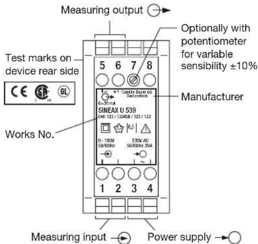
Connect the leads acc. to the instructions on nameplate.
Make sure that all cables are not live when making the connections! Impending danger by high input voltage or high power supply voltage!

Also note that, ...
... the data required to carry out the prescribed measurement must correspond to those marked on the nameplate of the SINEAX U 539 (-measuring input, measuring output and -power supply, see Fig. 6)!
... the resistance in the output circuit
- may not overrange the value
$$ R _ {\text { ext }} \max. [ k \Omega ] \leq \frac {1 5 \mathrm{V}}{I _ {\mathrm{AN}} [ \mathrm{mA} ]} $$
$$ \left(I _ {A N} = \text { current output end value }\right) $$
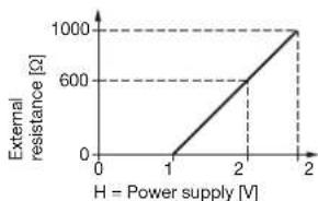
- with power supply via output leads (2-wire connection, output 4 - 20 mA) dependent on power supply H (12 - 32 V DC)
line
| H = Power supply [V] | External resistance [Ω] | |---|---| | 0 | 0 | | 1 | 0 | | 2 | 600 | | 2 | 1000 |4 3 2
$$ R _ {\text { ext }} \max. [ k \Omega ] = \frac {H [ V ] - 1 2 V}{2 0 m A} $$
- may not underrange the value
$$ R _ {\text { ext }} \min. [ k \Omega ] \geq \frac {U _ {A N} [ V ]}{1 0 m A} $$
$$ \left(U _ {A N} = \text { voltage output end value }\right) $$
... the measurement output cables should be twisted pairs and run as far as possible away from heavy current cables!
In all other respects, observe all local regulations when selecting the type of electrical cable and installing them!
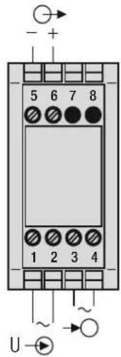
text_image
- + 5 6 7 8 1 2 3 4 UFig. 2. AC power supply
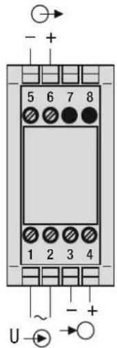
text_image
5 6 7 8 1 2 3 4 ~ U → →Fig. 3. DC power supply.
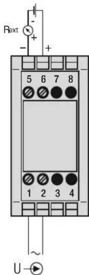
text_image
Rext + - + 5 6 7 8 1 2 3 4 UFig. 4. Power supply via output leads.
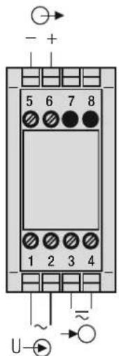
text_image
- + 5 6 7 8 1 2 3 4 ~ U-→Fig. 5. DC, AC power supply, in version with built-in DC, AC power pack.
I → = Voltage measuring input = Measuring output = Power supply
text_image
Measuring output Test marks on device rear side CE GL Works No. SINEAX U 539 Cnd: 123 / 122406 / 123 / 123 0-100V 50/80Hz 230V AC 50/80Hz 30Hz 1 2 3 4 Manufacturer Optionally with potentiometer for variable sensibility ±10% Measuring input → Power supply →Fig. 6. Declaration to type label.
6. Commissioning and maintenance
Switch on the power supply and the measuring input.
No maintenance is required.
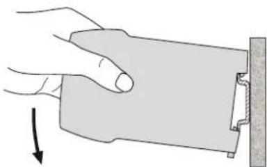
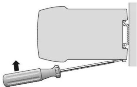
7. Releasing the transducer
Release the transducer from a top-hat rail as shown in Fig. 7.
natural_image
Diagram of a screwdriver inserted into a mechanical component, showing tool path and force direction (no text or symbols)Fig. 7
8. Instruments admissions

Germanischer Lloyd
Type approval certifi cate:
12 258-98 HH

CSA approved for USA and Canada
fi le-nr. 204767
C US
9. Dimensional drawing
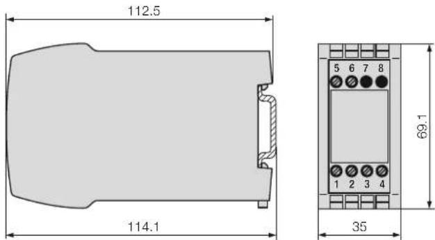
text_image
112.5 114.1 69.1 35Fig. 8. Housing type P8/35 onto a top hat rail (35 ×15 mm or 35×7.5 mm) acc. to EN 50 022.
FCC Compliance and Canadian DOC Statement
This equipment has been tested and found to comply with the limits for a Class A digital device, pursuant to both part 15 of the FCC Rules and the radio interference regulations of the Canadian Department of Communications: These limits are designed to provide reasonable protection against harmful interference when the equipment is operated in a commercial environment. This equipment generates, uses and can radiate radio frequency energy and, if not installed and used in accordance with the instruction manual, may cause harmful interference to radio communications. Operation of this equipment in a residential area is like to cause harmful interference in which case the user will be required to correct the interference at his own expense.
10. Konformitätserklärung / Certifi cat de conformité / Declaration of conformity
EG - KONFORMITÄTSERKLÄRUNG DECLARATION OF CONFORMITY

Dokument-Nr./
U539_CE-konf.DOC
Document.No.:
Hersteller/ Camille Bauer AG
Manufacturer: Switzerland
Address: CH-5610 Wohlen
Product name: Transducer for AC Voltage
Typ / Type: SINEAX U 539
The above mentioned product has been manufactured according to the regulations of the following European directives proven through compliance with the following standards:
Leiter Technik / Head of engineering
Qualitätsmanager / Quality manager
EG - KONFORMITÄTSERKLÄRUNG CAMILLE BAUER DECLARATION OF CONFORMITY
Dokument-Nr./
U539_2D_CE-konf.DOC
Document.No.:
Hersteller/ Camille Bauer AG
Manufacturer: Switzerland
Address: CH-5610 Wohlen
Product name: Transducer for AC Voltage
The above mentioned product has been manufactured according to the regulations of the following European directives proven through compliance with the following standards:
Leiter Technik / Head of engineering Qualitätsmanager / Quality manager