
KINAX HW730ModbusTCP - Measuring equipment Camille Bauer - Free user manual and instructions
Find the device manual for free KINAX HW730ModbusTCP Camille Bauer in PDF.
| Product type | Hollow shaft angular measurement converter |
| Brand | Camille Bauer |
| Model | KINAX HW730ModbusTCP |
| Power supply | Power over Ethernet (PoE), class 0 |
| Interface | Modbus TCP/IP (IEC 61158), 100BASE-TX |
| Transmission speed | 10 / 100 Mbit |
| Angular measurement range | 0 to 360° |
| Absolute accuracy | < ±0.15° (0.04% with 360°) |
| Resolution | 14 bits |
| Repeatability | < 0.1° |
| Hollow shaft diameter | Up to 30 mm (with reducing sleeves) |
| Starting torque | Max. 0.5 Nm |
| Housing material | Anodized aluminum EN AW-6060 T6 |
| Weight | Approx. 820 g |
| Protection type | IP67 (EN 60529) / IP69K (EN 40050-9) |
| Operating temperature | -40 to +85°C |
| Relative humidity | ≤95% non-condensing |
| Vibration resistance | ≤100 m/s² (10-500 Hz) according to EN 60068-2-6 |
| Shock resistance | 1000 m/s² (11 ms) according to EN 60068-2-27 |
| Electrical connections | M12x1/4-pin D-coded connector or M16x1.5 screw connection |
| Configuration software | CB-Manager (supplied on CD) |
| Warranty | 36 months |
| Maintenance | No maintenance required |
| Safety | Compliant with EN 61010-1 |
Frequently Asked Questions - KINAX HW730ModbusTCP Camille Bauer
User questions about KINAX HW730ModbusTCP Camille Bauer
0 question about this device. Answer the ones you know or ask your own.
Ask a new question about this device
Download the instructions for your Measuring equipment in PDF format for free! Find your manual KINAX HW730ModbusTCP - Camille Bauer and take your electronic device back in hand. On this page are published all the documents necessary for the use of your device. KINAX HW730ModbusTCP by Camille Bauer.
USER MANUAL KINAX HW730ModbusTCP Camille Bauer
Operating Instructions
Programmable hollow-shaft transmitter for angular position KINAX HW730-Modbus/TCP with PoE
CH-5610 Wohlen/Switzerland
Phone +41 56 618 21 11
Fax +41 56 618 21 21
info@cbmag.com
www.camillebauer.com
Informations concerning la manipulation.
1. Safety instructions
1.1 Symbols
The symbols in these instructions point out risks and have the following meaning:

Warning in case of risks.
Non-observance can result in malfunctioning.
Non-observance can result in malfunctioning and personal injury.

Information on proper product handling.
1.2 Intended use
- The angular position transmitter KINAX HW730-Modbus/ TCP with PoE is a precision instrument and serves the acquisition and provision of digital measured values. Use the transmitter for this purpose only.
- The angular position transmitter is not intended to measure rotation speed.
- The device is intended for installation in industrial plants and meets the requirements of EN 61010-1.
- Maritime device versions are only provided for approved environmental categories.
- Manufacturer is not liable for any damage caused by inappropriate handling, modification or any application not according to the intended purpose.
1.3 Commissioning

- Installation, assembly, setup and commissioning of the device has to be carried out exclusively by skilled workers.
- Observe manufacturer's operating instructions.
- Check all electric connections prior to commissioning the plant.
- If assembly, electric connection or other work on the device and the plant are not carried out properly, this may result in malfunctioning or breakdown of the device.
- Safety measures should be taken to avoid any danger to persons, any damage of the plant and any damage of the equipment due to breakdown or malfunctioning of the device.
- Do not operate the device outside of the limit values stated in the operating instructions.
1.4 Repair work and modifications

The disposal of devices and components may only be realised in accordance with good professional practice observing the country-specific regulations.
1.6 Transport and storage

Transport and store the devices exclusively in their original packaging. Do not drop devices or expose them to substantial shocks.
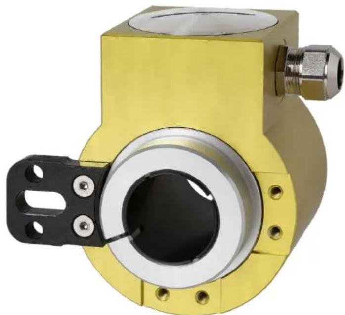
2. Scope of delivery
1 KINAX HW730-Modbus/TCP with PoE programmable hollow-shaft transmitter for angular position
1 HW730 torque support set 169 749
1 Safety instructions 172 734 (german, english, french)
1 Software and documentation CD 156 027
3. Application
KINAX HW730-Modbus/TCP with PoE is a robust absolute hollow shaft angular position transmitter which, due to its high mechanical load capacity, is particularly suited to applications in rough environments. It acquires the angular position of a shaft in a non-contact manner and makes it available via Modbus/TCP.
4. Main features
- Robust hollow-shaft transmitter for angular position
- Interface Modbus / TCP with Power over Ethernet (PoE)
Continuous hollow shaft up to 30mm - Highest degree of mechanical and electrical safety
- Waterproof and dustproof IP67/IP69K
- maintenance and wear-free
- Easy installation and fast commissioning
- Measuring range (zero point) and direction of rotation can be parameterised via Modbus/TCP
- Free on-site parameterising via Software CB Manager
- With maritime execution (formerly GL, Germanischer Lloyd) available
5. Technical data
5.1 General
Measured quantity: Angle of rotation
Measuring principle: Capacitive method
5.2 Measuring input
Angle measuring range: 0 ... 360irc
Hollow-shaft diameter: max. 030mm [1.181], reducing the diameter of the hollow shaft by casing adapter
Starting torque: max. 0.5 Nm [70.806 oz-in]
Sense of rotation: Adjustable
5.3 Measuring output
Power supply: Power over Ethernet (PoE), Class 0
Interface: Modbus TCP/IP (IEC 61158) 100BASE-TXI
Transmission rate: 10 / 100 MBit
5.4 Accuracy data
Absolute precision: < ± 0.15irc (0.04% by 360irc )
Resolution: 14 bit
Reproducibility: < 0.1irc
Influence of temperature
output current
Mounting position: Any
Connections: 8-pole spring-type terminal block via cable gland or sensor plug metal (M12 x 1 / 4-pole d-coded)
Weight: Approx. 820 g [28.925 oz]
5.6 Regulations
Spurious radiation: EN 61000-6-3
Immunity: EN 61 000-6-2
Test voltage: 750 V CC, 1 min. All connections against housing
Zulässige
5.7 Environmental conditions
Climatic rating: Temperature - 40 to +85 °C [-40... +185°F] Rel. humidity ≤ 95% non-condensing
Vibration resistance: ≤ 100m / s2 / 10... 500Hz acc. EN 60068-2-6
The network installation of the devices is done by means of the CB-Manager software. As soon as all devices have a unique network address they may be accessed by means of a suitable Modbus master or client.
The basics of Modbus TCP are contained in the document W2417e Modbus Basics.
6.1 Mapping
Address space
| Space | r/w | Address area | Function code | |
| Coil | Iisible inscriptible | 00001 - 09999 | 0x010x050x0F | Read Coil Status1)Force Single Coil1)Force Multiple Coils1) |
| Holding register | Iisible inscriptible | 40001 - 49999 | 0x030x060x10 | Read Holding RegistersForce Single Register1)Preset Multiple Registers |
not implemented
To reduce the commands, the device image was represented as far as possible in "holding registers".
Segments
| Adress | Description | Permitted function codes | |
| 40001 - 40003 | Actions | 0x03 | Read Holding Registers |
| 40101 - 40105 | General information | 0x10 | Preset Multiple Registers |
| 40201 - 40205 | Configuration | 0x06 | Force Single Registers |
| 40301 - 40315 | TCP/IP - Configuration | ||
| 40401 - 40416 | Name of device | ||
Syntax
| Adress | Start address of the described data block (register, coil or input status) |
| Description | Unique variable or structure description |
| Data type | Data type of variable (U: unsigned, INT: integer, 8/16/32 bit, REAL or CHAR[..]) |
| Default Value upon derivery or after a hardware reset | |
| Description | Exact details concerning the variable described |
| Length | Number of registers |
6.2 Device identification
The device is identified by "Read Slave ID".
Function 11h: Report Slave ID
Master telegram:
| Device address | Function |
| ADDR | 0x11 |
Slave telegram:
| Device Address | Function | Number data bytes | Slave ID | Sub ID | Data 2 |
| ADDR | 0x11 | 0x03 | 0x0A | 0xFF | 0x00 |
| Device ID | Sub-ID | Device Description | |
| 0x01 0x00 | VR660 | Temperature controller | |
| 0x02 0x00 | A200R | Display | |
| 0x03 0x01 | CAM | Universal measuring unit for heavy current variables | |
| 0x04 0x00 | APPLUS | Multifunctional | display |
| 0x05 0x00 | V604s | Universal transmitter | universal transmitter multi in/out |
| 0x05 0x01 | VB604s | Universal transmitter second Relay | Universal transmitter fast setting time |
| 0x05 0x03 | VQ604s | Universal transmitter | universal transmitter fast setting time |
| 0x07 0x00 | VS30 | Temperature transmitter | transmitter |
| 0x08 0x00 | DM5S | Multi transmitter | standard |
| 0x08 0x01 | DM5F | Multi transmitter | fast |
| 0x08 0x02 | DM5E | Multi transmitter | energy |
| 0x08 0x03 | DM5SC | Multi transmitter monitoring | monitoring |
| 0x09 0x00 | CAM Quality System | analysis ____________ | |
| 0xA0 A0FF | HW730 Transmitters | for angular position | |
| 0xB0 0xFF | CAM Profinet CAM Ethernet Buscard with Profinet | ||
6.3 Process image
Definition of all volatile and non-volatile parameters and variables.
6.4 Measured values
The measured angle is available in two different formats.
| Adress | Length | Designation | Typ | Description |
| 40001 | 2 | PHI_FLOAT | FLOAT | Measured value in degrees (0.0° ≤ PHI_FLOAT < 360.0°) |
| 40003 1 | PHI_INT UINT | NT16 The value for the 360° angle can be configured via NO_STEPS. (0 ≤ PHI_INT < NO_STEPS) | ||
6.5 General information
| Adresse | Length | Designation | Typ | Description |
| 40101 | 1 | FW_REVISION | UINT16 | Revisions number |
| 40102 | 1 | FW_VERSION | UINT16 | Firmware version Byte 1 Byte 0 v 1.00 1.00: Version number Hexadecimal representation of the version number |
| 40103 | 1 | MB_VERSION | UINT16 | Version of the Modbus image. |
| 40104 1 | RESERVE | UINT16 | Reserved | |
| 40105 | 2 | SERIAL | UINT32 | Serial number of the device |
6.6 Configuration
| Adresse | Length | Designation | Typ | Description |
| 40201 | 1 | CONFIG | UINT16 | Bit 0: Sense of rotation |
| 0 clockwise | ||||
| 1 counterclockwise | ||||
| Bit 2 ... 15: Reserved | ||||
| Bit 8 ... 15: Reserved |
| 40202 1 | NO_STEPS | UINT16 | Number of steps per 360° Default: 4096 |
| 40203 2 | ZERO | FLOAT | Zero point Default: 0.0 |
NO_STEPS refers to the subdivision of the entire measuring range of 0...360 into number of steps.
(E.g. NO_STEPS 100 means to divide 0...360 into 100 parts of 3.6irc )
| Adress | Length | Designation | Typ | Description |
| 10001 | 1 SET | ZERO COIL | Determine current angle to be the zero point |
6.7 Network configuration IPv4
| Adress | Length | Designation | Typ | Description |
| 40301 | 2 | IPv4 | UINT32 | IP-Adress |
| 40303 | 2 | SUBNETv4 | UINT32 | Subnetmaske |
| 40305 | 2 | GATEWAYv4 | UINT32 | Standard-Gateway |
Port 502 is always used for Modbus/TCP as a standard. HW730-ETH is always accessible via this port. Further connections can be alternatively realised via the following configured port.
| Adresse | Length | Designation | Typ | Description |
| 40315 | 1 | TCP_PORT | UINT16 | Alternative Modbus/TCP port |
6.12 Name of device
A name may be allocated to each device. This simplifies the identification of the device via the search service.
| Adresse | Length | Designation | Typ | Description |
| 40401 | 16 | NAME | CHAR[32] | Identification of the device in text form Allowed characters: ‘A’...‘Z’, ‘a’...‘z’, ‘_’, 0-terminated |
7. Mounting
See page 23.
8. Electrical connections
For connecting the external wires, the transmitter has a plug connector M12x1 / 4 poles d-coded or a cable glands M16x1.5. During the version with a cable glands the connection via a spring-type terminal block made in accordance with diagram of connections.
Permissible cable: Ethernet CAT5
Cable length: 100m
Connection allocation plug M12/4-pole d-coded
| Pin | Signal |
| 1 | Rx+ |
| 2 | Tx+ |
| 3 | Rx- |
| 4 | Tx- |
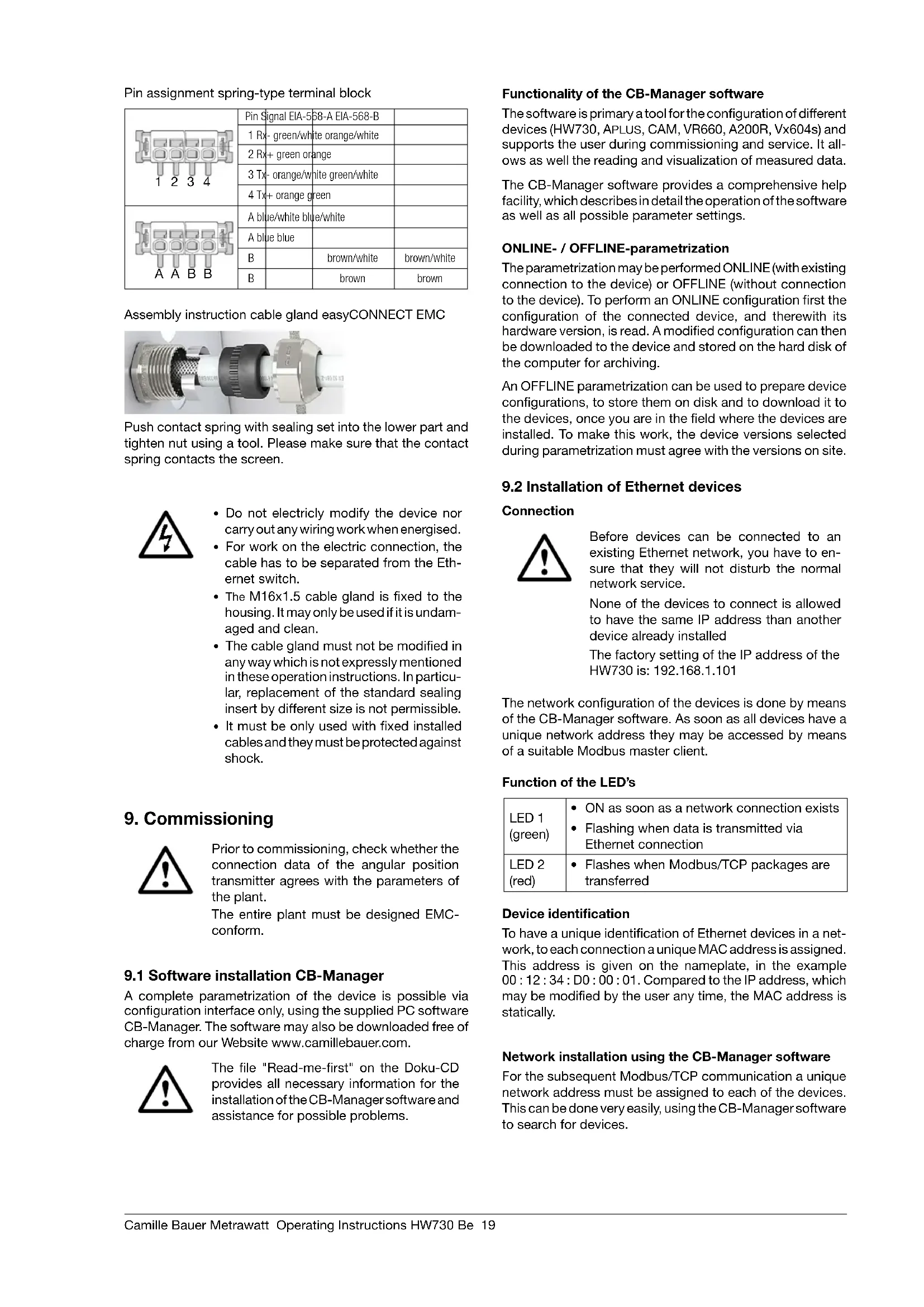
Pin assignment spring-type terminal block
| 1 2 3 4 | Pin Signal EIA-5B-A EIA-568-B | |
| 1 Rx - green/white orange/white | ||
| 2 Rx + green orange | ||
| 3 Tx - orange/white green/white | ||
| 4 Tx + orange green | ||
| A A B B | A blue/white blue/white | |
| A blue blue | ||
| B | ||
| B |
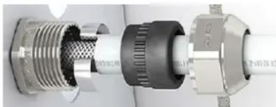
Assembly instruction cable gland easyCONNECT EMC
Push contact spring with sealing set into the lower part and tighten nut using a tool. Please make sure that the contact spring contacts the screen.
- Do not electricly modify the device nor carry out any wiring work when energised.
- For work on the electric connection, the cable has to be separated from the Ethernet switch.
- The M16x1.5 cable gland is fixed to the housing. It may only be used if it is undamaged and clean.
- The cable gland must not be modified in any way which is not expressly mentioned in these operation instructions. In particular, replacement of the standard sealing insert by different size is not permissible.
- It must be only used with fixed installed cables and they must be protected against shock.
9. Commissioning

Prior to commissioning, check whether the connection data of the angular position transmitter agrees with the parameters of the plant.
The entire plant must be designed EMC-conform.
9.1 Software installation CB-Manager
A complete parametrization of the device is possible via configuration interface only, using the supplied PC software CB-Manager. The software may also be downloaded free of charge from our Website www.camillebauer.com.

The file "Read-me-first" on the Doku-CD provides all necessary information for the installation of the CB-Manager software and assistance for possible problems.
Functionality of the CB-Manager software
The software is primary a tool for the configuration of different devices (HW730, APLUS, CAM, VR660, A200R, Vx604s) and supports the user during commissioning and service. It allows as well the reading and visualization of measured data.
The CB-Manager software provides a comprehensive help facility, which describes in detail the operation of the software as well as all possible parameter settings.
ONLINE-/ OFFLINE-parametrization
The parametrization may be performed ONLINE (with existing connection to the device) or OFFLINE (without connection to the device). To perform an ONLINE configuration first the configuration of the connected device, and therewith its hardware version, is read. A modified configuration can then be downloaded to the device and stored on the hard disk of the computer for archiving.
An OFFLINE parametrization can be used to prepare device configurations, to store them on disk and to download it to the devices, once you are in the field where the devices are installed. To make this work, the device versions selected during parametrization must agree with the versions on site.
9.2 Installation of Ethernet devices
Connection

Before devices can be connected to an existing Ethernet network, you have to ensure that they will not disturb the normal network service.
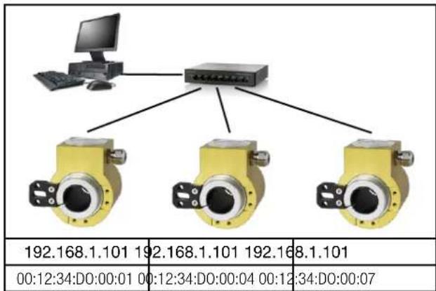
None of the devices to connect is allowed to have the same IP address than another device already installed
The factory setting of the IP address of the HW730 is: 192.168.1.101
The network configuration of the devices is done by means of the CB-Manager software. As soon as all devices have a unique network address they may be accessed by means of a suitable Modbus master client.
Function of the LED's
| LED 1 (green) | ON as soon as a network connection exists Flashing when data is transmitted via Ethernet connection |
| LED 2 (red) | Flashes when Modbus/TCP packages are transferred |
Device identification
To have a unique identification of Ethernet devices in a network, to each connection a unique MAC address is assigned. This address is given on the nameplate, in the example 00:12:34:D0:00:01.Compared to the IP address, which may be modified by the user any time, the MAC address is statically.
Network installation using the CB-Manager software
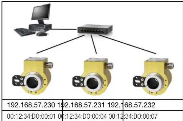
For the subsequent Modbus/TCP communication a unique network address must be assigned to each of the devices. This can be done very easily, using the CB-Manager software to search for devices.
As soon as to all the devices network settings with unique IP address have been assigned, they may be accessed and read using the Modbus/TCP protocol.
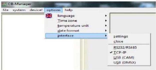
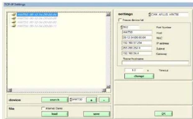
Select "settings" under options | interface. The interface type has to be set to "TCP-IP".
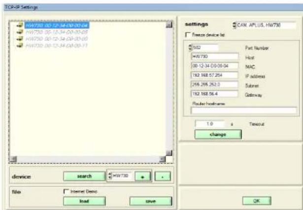
Devices in the local network
Set settings to "HW730". The devices may be identified via their MAC address which is stated on the name plate of the device.
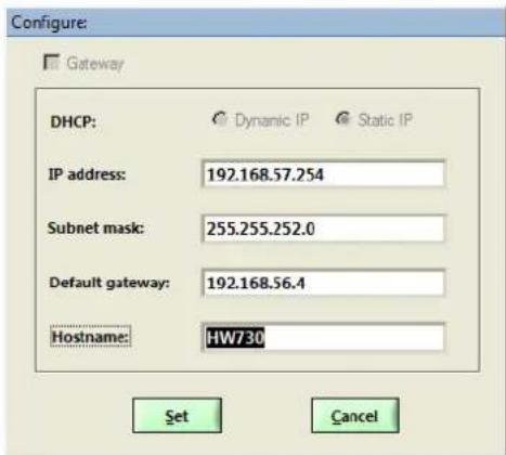
To assign a unique network address to a device, select it in the list and the click on "change".
The following settings have to be arranged with the network administrator:
- IP address: This one must be unique, i.e. may be assigned in the network only once.
- Subnet mask: Defines how many devices are directly addressable in the network. This setting is equal for all the devices.
- Default gateway: Is used to resolve addresses during communication between different networks. Should contain a valid address within the own network.
- Hostname: Individual designation for each device. Helps to identify the device in the device list.
Example: Initial position (all IPs are the same)
Example: Installed system (every device address unambiguously)
Devices outside the local network
Devices which are not in the same network as the PC (e.g. in the Internet) can not be found and have to be added manually to the device list by means of + . The type of the device must be selected previously. To each entry you have to assign a unique IP and MAC address, which are different from the initial value. Otherwise it's not possible to add further entries.
TCP ports for data transmission
As a standard Modbus/TCP communication is performed via TCP port 502. However, the port for the Modbus/TCP telegrams may be modified. You may provide a unique port to each of the devices, e.g. 2002, 2003, 2004 etc.. The setting of the Modbus TCP port is done as shown above. Independent of these setting a communication via port 502 is always supported. The device allows at least 5 connections to different clients at the same time.
10. Maintenance
The device is free of maintenance. Repairs may only be carried out by authorized authorities.
11. Terms of warranty
Camille Bauer Metrawatt AG warrants the flawless condition of the product with respect to material, manufacturing and function and offers a standard warranty of 36 months. Such warranty becomes effective upon delivery of the product to the customer. Camille Bauer Metrawatt AG reserves the right to amend the terms of warranty any time with future effect.
Any defects shall be communicated by the buyer immediately after discovery. The rejected products shall be sent in proper packaging and with sufficient transport protection to one of our authorised service centres. The sender shall bear the shipping risk.
Any defects arising due to improper treatment, faulty installation, mechanical damage, failure to perform maintenance work, inappropriate use and connection to improper power supply shall be excluded from any kind of warranty.
In case of repair work, alterations or tampering on the part of the buyer or any unauthorised third parties, any warranty claim shall lapse.
12. Disclaimer of liability
The content of this document has been reviewed to ensure correctness. Nevertheless it may contain errors or inconsistencies and we cannot guarantee completeness and correctness. This is especially true for different language versions of this document. This document is regularly reviewed and updated. Necessary corrections will be included in subsequent version and are available via our webpage http://www.camillebauer.com.
13. Specification and ordering information
| Description | Locking code | Impossible with locking code | Article No / Feature | ||||
| KINAX HW730 Order code 730 - xxxxxx xx 730 - | |||||||
| 1. VersionStandard 1 | |||||||
| ATEX EX II 2G Ex ia IIC T4 GbII 2D Ex ia IIC T80°C Db | A | 2 | |||||
| ATEX EX II 2D Ex tb IIC T80°C Db A 3 | |||||||
| IECEEx Ex ia IIC T4 GbEx ia IIC T80°C Db | A | 4 | |||||
| IECEx Ex tb IIC T80°C Db A 5 | |||||||
| 2. Angle area mechanicallySingle-Turn (360°) | 1 | ||||||
| 3. Hollow-shaft diameterHollow-shaft 10 mm [0.393", electrically insulating | 1 | ||||||
| Hollow-shaft 12 mm [0.472", electrically insulating | 2 | ||||||
| Hollow-shaft 16 mm [0.629", electrically insulating | 3 | ||||||
| Hollow-shaft 20 mm [0.787", electrically insulating | 4 | ||||||
| Hollow-shaft 30 mm [1.181", non-insulating, standard | 5 | ||||||
| Hollow-shaft 18 mm, electrically insulatinge | 6 | ||||||
| Hollow-shaft 1/2" (12.7mm), electrically insulating | A | ||||||
| Hollow-shaft 5/8" (15.875mm), electrically insulating | B | ||||||
| Hollow-shaft 3/4"(19.05mm), electrically insulating | C | ||||||
| Hollow-shaft 7/8" (22.225mm), electrically insulating | D | ||||||
| Hollow-shaft 1" (25.4mm), electrically insulating | E | ||||||
| 4. Torque supportStandard 1 | |||||||
| 5. Output variableCurrent, 4...20 mA, two-wire | B 1 | ||||||
| Modbus TCP/IP with PoE | C | A | 2 | ||||
| 6. Electrical connectionsGland standard | 1 | ||||||
| Gland with increased strain relief | A | 2 | |||||
| Sensor plug M12x1 | A, C | 3 | |||||
| Sensor plug M12x1 d-coded | A, B | 4 | |||||
| Description | Locking code | Impossible with locking code | Article No / Feature | ||||
| KINAX HW730 Order code 730 - xxxx xxxx xx 730 - | |||||||
| 7. Test protocoleWithout protocole 0 | |||||||
| Protocole German D | |||||||
| Protocole English E | |||||||
| 8. Direction of rotationDirection of rotation clockwise J 0 | |||||||
| Direction of rotation counter-clockwise J, G C 1 | |||||||
| V-characteristic K, G C 2 | |||||||
| 9. Measuring rangeBasic configuration (linear, 0 ... 360°) | K, G 0 | ||||||
| [°angle], 0...end value: | Switching point: | C, K 9 | |||||
| V-characteristic[±° angle] | vmax1: | vmin1: | C, J | Z | |||
| vmax2: | vmin2: | ||||||
| lout[mA]20.543.8angle of rotation [°] | |||||||
| 43.8angle of rotation [°] | |||||||
| 10. Climatic rating / Marine versionStandard (rel. humidity annual average ≤95%) | 0 | ||||||
| Maritime execution (formerly Germ. Lloyd) | G | ||||||
Mounting
Installation example
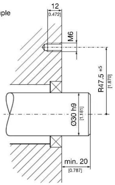
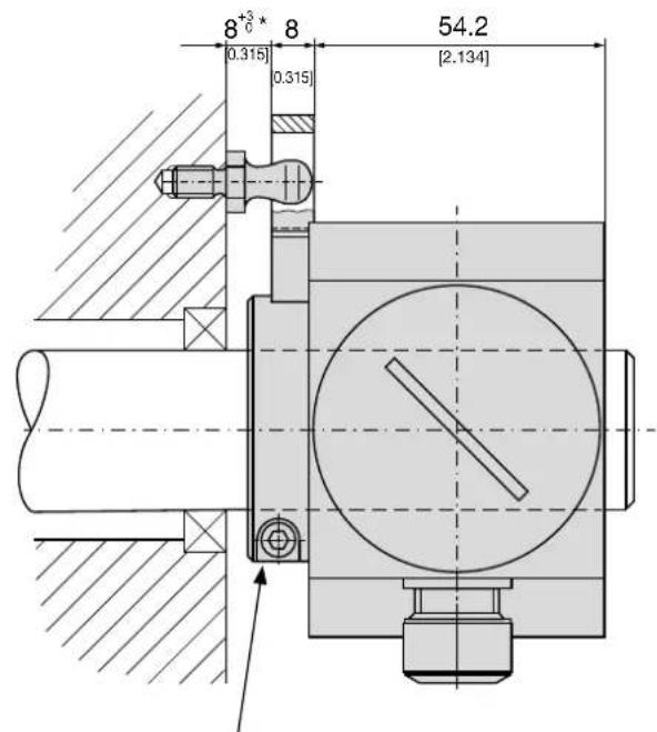
max. tightening torque 3.4 Nm [481.48 in-oz]
* With spacers, this measure will be increased.
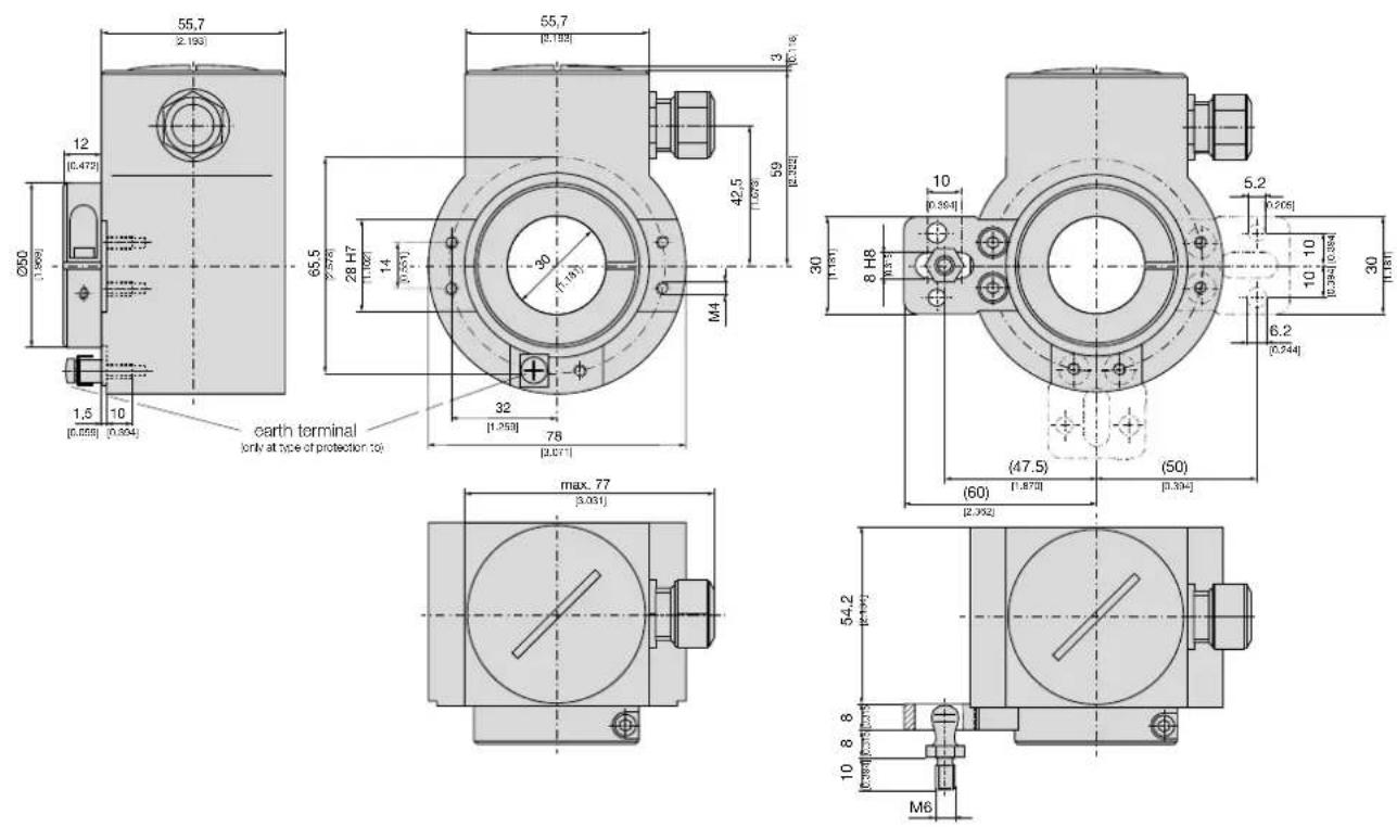
Dimensional drawing


- Operating Instructions
- Programmable hollow-shaft transmitter for angular position KINAX HW730-Modbus/TCP with PoE
- Safety instructions
- Symbols
- Intended use
- Commissioning
- Repair work and modifications
- Transport and storage
- Scope of delivery
- Application
- Main features
- Technical data
- General
- Measuring input
- Measuring output
- Accuracy data
- Regulations
- Environmental conditions
- Mapping
- Device identification
- Function 11h: Report Slave ID
- Process image
- Measured values
- Network configuration IPv4
- Name of device
- Mounting
- Electrical connections
- Commissioning
- Software installation CB-Manager
- Functionality of the CB-Manager software
- ONLINE-/ OFFLINE-parametrization
- Installation of Ethernet devices
- Connection
- Device identification
- Network installation using the CB-Manager software
- Devices in the local network
- Devices outside the local network
- TCP ports for data transmission
- Maintenance
- Terms of warranty
- Disclaimer of liability
- Specification and ordering information
- Mounting
- Dimensional drawing
Brand : Camille Bauer
Model : KINAX HW730ModbusTCP
Category : Measuring equipment