Sineax I552 - Measuring equipment Camille Bauer - Free user manual and instructions
Find the device manual for free Sineax I552 Camille Bauer in PDF.

User questions about Sineax I552 Camille Bauer
0 question about this device. Answer the ones you know or ask your own.
Ask a new question about this device
Download the instructions for your Measuring equipment in PDF format for free! Find your manual Sineax I552 - Camille Bauer and take your electronic device back in hand. On this page are published all the documents necessary for the use of your device. Sineax I552 by Camille Bauer.
USER MANUAL Sineax I552 Camille Bauer
Operating Instructions
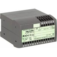
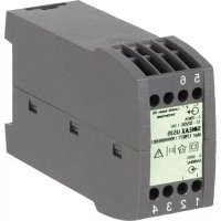
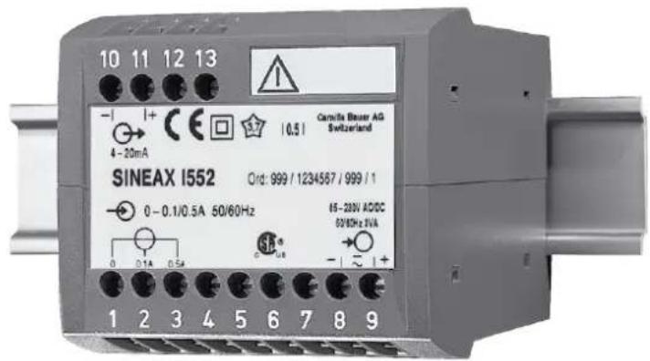
Transducer for AC current SINEAX I552
text_image
10 11 12 13 - | + CE | 0.5 | Camilla Bauer AG Switzerland 4 - 20mA SINEAX I552 Ord: 999 / 1234567 / 999 / 1 0 - 0.1/0.5A 50/60Hz 15 - 20V AC/DC 60/60Hz 5VA 0 0.1A 0.5A - | ~ | + 1 2 3 4 5 6 7 8 9I552 B d-f-e 131 219-09 12.22
PM1000994 000 03
Betriebsanleitung
Operating Instructions
Transducer for AC current SINEAX I552....9

The instruments must only be disposed of in the correct way!
natural_image
Illustration of a hand holding a rectangular object with a downward arrow indicating motion (no text or symbols)natural_image
Diagram of a screwdriver holding a rectangular object with a curved handle, showing an arrow indicating direction (no text or symbols present)Bild 8
Humidité relative: ≤ 75%, sans condensation
Altitude: 2000 m max.
natural_image
Illustration of a hand holding a rectangular object with a downward arrow indicating motion (no text or symbols)natural_image
Diagram of a screwdriver inserted into a mechanical component, showing a tool and arrow (no text or symbols)Fig. 8
Safety precautions to be strictly observed are marked with following symbols in the Operating Instructions:


Contents
- Read first and then ....9
- Brief description....9
- Technical data....9
- Mounting 9
- Electrical connections....10
- Adjustable measuring range ..... 11
- Commissioning and maintenance....11
- Releasing the transducer 11
- Instruments admissions....11
- Dimensional drawing....11
1. Read first and then ...

The proper and safe operation of the device assumes that the Operating Instructions is read carefully and the safety warnings given in the various Sections
- Mounting
- Electrical connections
- Adjustable measuring range are observed.
The device should only be handled by appropriately trained personnel who are familiar with it and authorised to work in electrical installations.
Unauthorized repair or alteration of the unit invalidates the warranty.
2. Brief description
The SINEAX I552 measuring transducer is used to convert a sine-wave or distorted AC current.
The output signal, in the form of a load independent DC current or voltage, is proportional to the measured value.
3. Technical data
Measuring input

Nominal frequency:
50/60 or 400 Hz
Nominal input current: CE: 0 - 0.1 / 0.5 to 0 - 1.2 / 6 A
CSA: 0 - 0.1 / 0.5 to 0 - 1 / 5 A
Measuring output

DC current: 0(0.2) - 1 to 0(4) - 20 mA
Burden voltage: 15 V
External resistance: R . [k]≤15 VI_AN[mA] I_AN=Full output value
DC voltage: 0(0.2) - 1 to 0(2) - 10 V
External resistance: R _ext min. [kΩ] ≥ _A[V]2mA
Response time: 50 or 300 ms
Power supply → ○
AC/DC power pack (DC or 50/60 Hz)
| Rated voltage Tolerance | |
| 85 - 230 V DC/AC | DC - 15 to + 33% |
| 24 - 60 V DC/AC | AC ± 15% |
Power consumption: 3 VA
Option: Connected to the low tension terminal
side 12 and 13 see Figs. 4 and 5
24 V AC or 24 - 60 V DC
Accuracy (acc. to IEC 688)
Reference value: Output end value
Basic accuracy: Class 0.5
Safety
Pollution degree: 2
Installation category: III
Environmental conditions
Operating temperature: -10 to +55 °C
Storage temperature: -40 to +70 °C
Relative humidity: ≤ 75%, no dew
Altitude: 2000 m max.
Indoor use statement
4. Mounting
The SINEAX I552 can be mounted on a top-hat rail.

Note "Environmental conditions" in Section
"3. Technical data" when determining the place of installation!
Simply clip the device onto the top-hat rail (EN 50 022) (see Fig. 1).
natural_image
Illustration of a hand holding a rectangular object with a downward arrow indicating motion (no text or symbols)Fig. 1. Mounting onto top-hat rail 35 × 15 or 35 × 7.5 mm.
5. Electrical connections
Connect the electrical conductors acc. to the instructions on type label.
Make sure that all input cables are not live (potential-free) when making the connections!
Impending danger by high power supply voltage!
Take care of current transformers!

Also note that, ...
... the data required to carry out the prescribed measurement must correspond to those marked on the nameplate of the SINEAX 1552 (-measuring input, measuring output and -power supply, see Fig. 6)!
... the resistance in the output circuit may not over-range the current output value
$$ R _ {\text { ext }} \max. [ k \Omega ] \leq \frac {1 5 V}{I _ {A N} [ m A ]} $$
$$ \left(I _ {A N} = \text { current output value }\right) $$
... and not underrange the voltage output value
$$ R _ {\text { ext }} \min. [ k \Omega ] \geq \frac {U _ {\mathrm{AN}} [ V ]}{2 \mathrm{mA}} $$
$$ \dots (U _ {A N} = \text { voltage output value })! $$
... the measurement output cables should be twisted pairs and run as far as possible away from heavy current cables!
In all other respects, observe all local regulations when selecting the type of electrical cable and installing them!
text_image
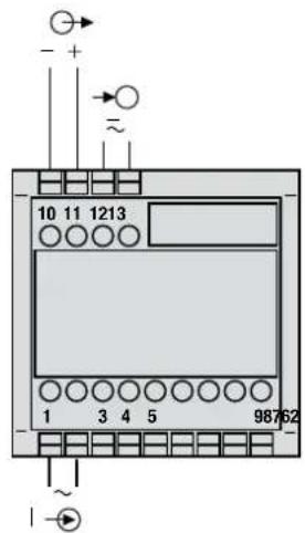
10 11 1213 1 3 4 5 987 62Fig. 4. For measurement with 1st (lower) measuring range, power supply connected to the low tension terminal side 12 and 13.
text_image
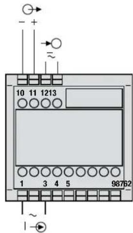
10 11 1213 1 3 4 5 98762Fig. 5. For measurement with 2nd (higher) measuring range, power supply connected to the low tension terminal side 12 and 13.
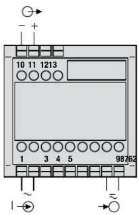
I → = Measuring input
→ = Measuring output
→○ = Power supply
text_image
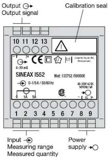
Output Output signal 10 11 12 13 4-20 mA SINEAX I552 Mat: 133752/000000 D-1/5A / 50/60 Hz 85-250V DC DC 50VDC DC 2.4A Input Measuring range Measured quantity Power supplyFig. 6. Declaration to type label.
text_image
10 11 1213 1 3 4 5 98762Fig. 2. For measurement with 1st (lower) measuring range, power supply connected to terminals 8 and 9.
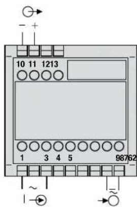
text_image
10 11 1213 1 3 4 5 98762 ~Fig. 3. For measurement with 2nd (higher) measuring range, power supply connected to terminals 8 and 9.
| Symbol | Meaning |
| Double insulation, device of protection class 2 | |
| Test voltage of insulation according to IEC60051: AC 3.7 kV | |
| |0,5| | Class icon to the EN60688: error limit 0.5% of span |
| CE conformity mark. The device fulfills the requirements of the applicable EC directives. | |
| CSA approved for USA and Canada file-nr. 204767 | |
| Caution!General hazard point.Read the operating instructions. | |
 | General symbol: Input |
 | General symbol: Output |
 | General symbol: Power supply |
 | Measurement category CAT III for current and vol-tage inputs |
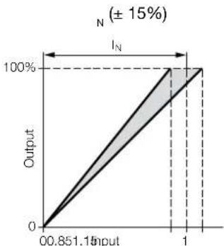
6. Adjustable measuring range
Reliably isolate the measuring input from dangerous voltages.
Setting: Admissible alteration of full scale
output, variable sensitivity, adjustable with potentiometer P200.
Setting range:
0.85 - 1.15 · 1
line
| Input | Output | |-------|--------| | 0.85115 | 0 | | 1 | 100% |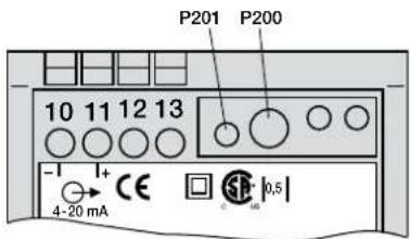
text_image
P201 P200 10 11 12 13 -I I+ CE 4-20 mA S 10,5Fig. 7. Locations of the potentiometers P201 and P200.
7. Commissioning and maintenance
Switch on the power supply and the measuring input. It is possible during the operation to disconnect the output line and to connect a check instrument, e.g. for a functional test. No maintenance is required.
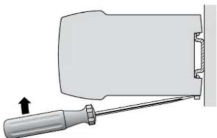
8. Releasing the transducer
Release the transducer from a top-hat rail as shown in Fig. 8.
natural_image
Diagram of a screwdriver inserted into a mechanical component, showing a force direction (no text or symbols)Fig. 8
9. Instruments admissions
With maritime execution
Type approval certificate: 12 258-98 HH

CSA approved for USA and Canada
file-nr. 204767
FCC Compliance and Canadian DOC Statement
This equipment has been tested and found to comply with the limits for a Class A digital device, pursuant to both part 15 of the FCC Rules and the radio interference regulations of the Canadian Department of Communications: These limits are designed to provide reasonable protection against harmful interference when the equipment is operated in a commercial environment. This equipment generates, uses and can radiate radio frequency energy and, if not installed and used in accordance with the instruction manual, may cause harmful interference to radio communications. Operation of this equipment in a residential area is like to cause harmful interference in which case the user will be required to correct the interference at his own expense.
10. Dimensional drawing
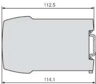
text_image
112.5 114.1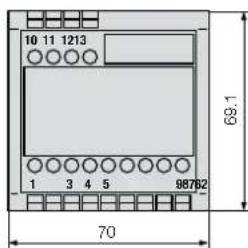
text_image
10 11 1213 69.1 1 3 4 5 98762 70Fig. 9. Housing type P13/70 clipped onto a top-hat rail (35×15 mm or 35×7.5 mm, acc. to EN 50 022).