Curve - Radio MOTOROLA - Free user manual and instructions
Find the device manual for free Curve MOTOROLA in PDF.

User questions about Curve MOTOROLA
0 question about this device. Answer the ones you know or ask your own.
Ask a new question about this device
Download the instructions for your Radio in PDF format for free! Find your manual Curve - MOTOROLA and take your electronic device back in hand. On this page are published all the documents necessary for the use of your device. Curve by MOTOROLA.
USER MANUAL Curve MOTOROLA
Non-Keypad Portable Radio User Guide
Contents
Supplier's Declaration of Conformity....6
Product Safety and RF Exposure Compliance....8
Notice to Users (FCC and ISED)....9
Batteries, Chargers, and Audio Accessories Safety Information....10
Operational Safety Guidelines....10
Acoustic Safety....11
Computer Software Copyrights....12
Intellectual Property and Regulatory Notices....13
Chapter 1: Introduction....14
Chapter 2: Maintenance.... 15
2.1 Use and Care....15
Chapter 3: Battery Features....16
3.1 Battery Specifications....16
3.2 Motorola Solutions Authorized Batteries....16
3.3 Battery Recycling and Disposal.... 16
3.4 Battery Life....17
3.5 Battery Status....17
Chapter 4: Charging the Batteries....18
4.1 Charging a Stand-Alone Battery....18
4.2 Charging with the Drop-In Tray Single-Unit Charger (SUC)....18
4.3 Charging the Radio and the Battery Using a Curve Series 6-Pocket Multi-Unit Charger—Optional Accessory 19
4.4 Estimated Charging Time....20
4.5 Charger LED Indication....20
Chapter 5: Curve, DLR, and DTR Radios Compatibility .... 22
Chapter 6: Radio Overview.... 23
6.1 Radio Controls and Indicators.... 23
6.2 Radio Specifications....25
Chapter 7: Getting Started....26
7.1 Attaching the Battery....26
7.2 Removing the Battery.... 26
7.3 Attaching the Holster....27
7.4 Turning the Radio On or Off....27
7.5 Adjusting the Volume.... 27
7.6 Checking the Battery Status....28
7.7 Checking Wi-Fi Strength Status.... 28
Chapter 8: General Radio Operations....29
8.1 Transmitting and Receiving Calls.... 29
8.2 Talk Permit Tone....29
8.3 Talking to a Group in Channels.... 30
8.4 Browsing or Selecting Channels....30
8.5 Starting Private Reply.... 30
8.6 Talk Range....30
8.7 Top Button Options....31
8.8 Radio Status....31
Chapter 9: Special Radio Call Features....33
9.1 Private Reply....33
9.1.1 Starting Private Reply.... 37
9.1.2 Private Reply Status Indicator....37
9.2 Direct Call....38
9.2.1 Direct Call Status Indicator....41
9.3 Private Reply and Direct Call Frequently Asked Questions....41
9.4 Call All Available....43
9.4.1 Call All Available Status Indicator....47
9.5 Page All Available.... 47
9.5.1 Page All Available Status Indicator....51
Chapter 10: Advanced Features....52
10.1 Voice Assistant Mode Features....52
10.1.1 Voice Assistant Mode Indicators....53
10.1.2 Subscription Activation for Motorola Solutions Voice Assistant Services.... 54
10.1.3 Virtual Channel....54
10.1.3.1 Joining Virtual Channel.... 54
10.1.3.2 Leaving Virtual Channel....55
10.1.4 Best Practices When Using Voice Assistant Features.... 56
10.1.5 Voice Assistant Feedback Error Definition....57
10.1.6 Voice Assistant Message Query....58
10.1.7 Login and Logout of Voice Assistant Mode....59
10.1.8 Logout of Voice Assistant Mode.... 59
10.1.9 Making Direct Call in Voice Assistant Mode....60
10.1.10 Recording Voice Message....60
10.1.11 Playing and Ending Voice Message.... 62
10.2 Auto Power off Features....63
10.2.1 Initiating Auto Power Off 63
10.3 Scan....63
10.3.1 Enabling or Disabling Scan....64
MN007944A01-AH Contents
10.3.2 Scan Status Indicator....64
10.4 Favorite Contact List....64
10.4.1 Entering Favorite Contact List Menu....64
10.4.2 Exiting Favorite Contact List Menu....64
10.5 Real Time Alert....65
10.5.1 Transmitting Real Time Alert....65
10.5.2 Receiving Real Time Alert 65
10.5.3 Canceling Real Time Alert....66
10.6 Task Reminder....66
10.6.1 Enabling or Disabling Reminder Timer.... 66
10.6.2 Reminder Timer Expires....67
10.6.3 Curve Portal Intelligent Insight....67
10.6.4 Task Reminder Frequently Asked Questions.... 68
Chapter 11: Advanced Configuration Mode....69
11.1 Entering Advanced Configuration Mode....69
11.2 Browsing Advanced Configuration Options....70
11.2.1 Entering Current PROFILE ID Number....71
11.2.2 Changing PROFILE ID Number....72
11.2.3 Changing PROFILE ID Number in Sub-Menu....72
11.2.4 Confirming Modified PROFILE ID Number.... 73
11.2.5 Setting Maximum Channels....74
11.2.6 Entering Top Button - Current Feature....75
11.2.6.1 Browsing Top Button - Sub-Menu Options.... 75
11.2.7 Setting MIC Gain....76
11.2.8 Setting Home Channel....77
11.2.9 Resetting to Factory Defaults....78
11.2.9.1 Radio Factory Default Settings....78
Chapter 12: Customer Programming Software....80
12.1 Setting Radio to Customer Programming Software....80
12.2 Customer Programming Software Basic Menu Instructions....81
Chapter 13: Cloning Mode....87
13.1 Configuring Serial/Profile ID Cloning Mode 87
13.2 Configuring OTA Wi-Fi Cloning Mode 88
13.3 Clone Mode in Multi-Unit Charger....89
13.3.1 Configuring Cloning Mode in Multi-Unit Charger....90
13.4 Configuring Cloning Mode Using Radio to Radio Cloning Cable....90
13.5 Cloning Mode Status Indicator....91
13.6 Troubleshooting Cloning Mode.... 91
13.7 Cloning Mode Using Wireless PROFILE ID Number 92
13.7.1 Configuring Cloning Mode Using Wireless PROFILE ID Number 92
13.8 OTA Wi-Fi Cloning....93
13.8.1 Entering OTA Wi-Fi Cloning Mode....93
Chapter 14: Troubleshooting....95
Chapter 15: Motorola Solutions Limited Warranty....98
15.1 Warranty....98
15.2 Products and Accessories....98
15.3 Exclusions....98
15.4 Software....99
15.5 Warranty Coverage.... 100
15.6 How to Obtain Warranty Service or Other Information....100
15.7 Patent Notice.... 100
15.8 Export Law Assurances.... 100
Appendix A: Accessories....101
Supplier's Declaration of Conformity
Supplier's Declaration of Conformity
Per FCC CFR 47 Part 2 Section 2.1077(a)

Responsible Party
Name: Motorola Solutions, Inc.
Address: 2000 Progress Pkwy, Schaumburg, IL. 60196
Phone Number: 1-800-927-2744
Hereby declares that the product:
Model Name: Curve
conforms to the following regulations:
FCC Part 15, subpart B, section 15.107(a), 15.107(d), and section 15.109(a)
Class B Digital Device
As a personal computer peripheral, this device complies with Part 15 of the FCC Rules. Operation is subject to the following two conditions:
-
This device may not cause harmful interference, and
-
This device must accept any interference received, including interference that may cause undesired operation.

NOTE:
This equipment has been tested and found to comply with the limits for a Class B digital device, pursuant to part 15 of the FCC Rules. These limits are designed to provide reasonable protection against harmful interference in a residential installation. This equipment generates, uses and can radiate radio frequency energy and, if not installed and used in accordance with the instructions, may cause harmful interference to radio communications. However, there is no guarantee that interference will not occur in a particular installation.
If this equipment does cause harmful interference to radio or television reception, which can be determined by turning the equipment off and on, the user is encouraged to try to correct the interference by one or more of the following measures:
● Reorient or relocate the receiving antenna.
- Increase the separation between the equipment and receiver.
- Connect the equipment into an outlet on a circuit different from that to which the receiver is connected.
- Consult the dealer or an experienced radio or TV technician for help.
Innovation, Science, and Economic Development Canada (ISED) WLAN Statement

CAUTION:
- The maximum antenna gain permitted for devices in the band 5752–5850 MHz shall be such that the equipment still complies with e.i.r.p. limits specified for point-to-point and non-point-to-point operation as appropriate.
- The worst case tilt angle(s) necessary to remain compliant with the e.i.r.p. elevation mask requirement set forth in Section 6.2.2 (3) shall be clearly indicated.
- User should also be advised that high-power radars are allocated as primary users (i.e. priority users) of the bands 5650–5850 MHz and that these radars could cause interference and/or damage to LE-LAN devices.
Product Safety and RF Exposure Compliance
CAUTION: This radio is restricted to occupational use only to satisfy FCC RF energy exposure requirements. Before using this product, read the Product Safety and RF Exposure booklet enclosed with your radio which contains important operating instructions for safe usage and RF energy awareness and control for compliance with applicable standards and regulations.
For a list of Motorola Solutions-approved antennas, batteries, and other accessories, visit http://www.motorolasolutions.com
Notice to Users (FCC and ISED)
The business two-way radios operate in the license-free 900 MHz ISM Band and are subject to the Rules and Regulations of the Federal Communications Commission (FCC).
This device complies with Part 15 of the FCC rules and Innovation, Science, and Economic Development Canada (ISED) license-exempt RSS's per the following conditions:
- This device may not cause harmful interference.
- This device must accept any interference received, including interference that may cause undesired operation.
- Changes or modifications made to this device, not expressly approved by Motorola Solutions, could void the authority of the user to operate this equipment.
To comply with FCC/ISED requirements, transmitter adjustments should be made only by or under the supervision of a technically qualified person to perform transmitter maintenance and repairs. Replacement of any transmitter component such as crystal, semiconductor, and other that are not authorized by the FCC/ISED equipment authorization for this radio violates FCC/ISED rules.

NOTE:
Use of this radio outside the country where it was intended to be distributed is subject to government regulations and may be prohibited.
Batteries, Chargers, and Audio Accessories Safety Information
This document contains important safety and operating instructions. Read these instructions carefully and save them for future reference. Before using the battery charger, read all the instructions and cautionary markings on:
- the charger
-
the battery
● the radio attached with battery -
To reduce risk of injury, charge only the rechargeable Motorola Solutions-authorized batteries. Charging the other batteries may cause explosion, personal injury, and damage.
- Use of accessories not recommended by Motorola Solutions may result in fire, electric shock, or injury.
- To reduce damage to the electric plug and cord, pull by plug rather than the cord when disconnecting the charger.
- An extension cord should not be used unless necessary. Use of an improper extension cord may result in fire and electric shock. If an extension cord must be used, make sure that the cord size is 18 AWG for lengths up to 2.0 m (6.5 feet), and 16 AWG for lengths up to 3.0 m (9.8 feet).
- Do not operate the charger if it has been broken or damaged in any way. Take it to any qualified Motorola Solutions service representatives.
- Do not disassemble the charger; it is not repairable and replacement parts are not available. Disassembly of the charger may result in risk of electrical shock or fire.
- To reduce risk of electric shock, unplug the charger from the AC outlet before attempting any maintenance or cleaning.
Operational Safety Guidelines
- Turn off the radio while charging.
- The charger is not suitable for outdoor. Use only in dry locations or conditions.
- Disconnect charger from line voltage by removing the main plug.
- Connect the equipment to an outlet, which is easy to access and near.
- For equipment using fuses, fuse replacements must comply with the type and rating specified in the equipment instructions.
- The maximum ambient temperature around the power supply equipment must not exceed 40 °C (104 °F).
● Make sure that the cord is not stepped on, tripped over, subjected to water, damage, or stress.
Acoustic Safety

CAUTION: Exposure to loud noises from any source for extended periods of time may temporarily or permanently affect your hearing. The louder the radio volume, the less time is required before your hearing can be affected. Hearing damage from loud noises is sometimes undetectable at first and can have a cumulative effect.
To protect your hearing:
- Use the lowest volume necessary to do your job.
- Increase the volume only if you are in noisy surroundings.
- Reduce the volume before connecting headset or earpiece.
- Limit the amount of time you use headsets or earpieces at high volume.
- If you experience hearing discomfort, ringing in your ears, or speeches that are muffled, you should stop listening to your radio through your headset or earpiece, and have your hearing checked by your doctor.
Computer Software Copyrights
The Motorola Solutions products described in this manual may include copyrighted Motorola Solutions computer programs stored in semiconductor memories or other media. Laws in the United States and other countries preserve for Motorola Solutions certain exclusive rights for copyrighted computer programs, including, but not limited to, the exclusive right to copy or reproduce in any form the copyrighted computer program. Accordingly, any copyrighted Motorola Solutions computer programs contained in the Motorola Solutions products described in this manual may not be copied, reproduced, modified, reverse-engineered, or distributed in any manner without the express written permission of Motorola Solutions.
Furthermore, the purchase of Motorola Solutions products shall not be deemed to grant either directly or by implication, estoppel, or otherwise, any license under the copyrights, patents or patent applications of Motorola Solutions, except for the normal non-exclusive license to use that arises by operation of law in the sale of a product.
The AMBE+2™ voice compression software included in this product is protected by intellectual property rights including patent rights, copyrights and trade secrets of Digital Voice Systems, Inc. This voice compression technology is licensed solely for use as is within the Communications Equipment. US Patent Nos.: #8,595,002 B2, #8,359,197, #8,315,860, #8,200,497, #7,970,606, #6,912,495 B2, #6,199,037 B1, #5,826,222, #5,754,974, #5,701,390, and #5,715,365.
Intellectual Property and Regulatory Notices
Copyrights
The Motorola Solutions products described in this document may include copyrighted Motorola Solutions computer programs. Laws in the United States and other countries preserve for Motorola Solutions certain exclusive rights for copyrighted computer programs. Accordingly, any copyrighted Motorola Solutions computer programs contained in the Motorola Solutions products described in this document may not be copied or reproduced in any manner without the express written permission of Motorola Solutions.
No part of this document may be reproduced, transmitted, stored in a retrieval system, or translated into any language or computer language, in any form or by any means, without the prior written permission of Motorola Solutions, Inc.
Trademarks
MOTOROLA, MOTO, MOTOROLA SOLUTIONS, and the Stylized M Logo are trademarks or registered trademarks of Motorola Trademark Holdings, LLC and are used under license. All other trademarks are the property of their respective owners.
License Rights
The purchase of Motorola Solutions products shall not be deemed to grant either directly or by implication, estoppel or otherwise, any license under the copyrights, patents or patent applications of Motorola Solutions, except for the normal nonexclusive, royalty-free license to use that arises by operation of law in the sale of a product.
Open Source Content
This product may contain Open Source software used under license. Refer to the product installation media for full Open Source Legal Notices and Attribution content.
European Union (EU) and United Kingdom (UK) Waste of Electrical and Electronic Equipment (WEEE) Directive

The European Union's WEEE directive and the UK's WEEE regulation require that products sold into EU countries and the UK must have the crossed-out wheelie bin label on the product (or the package in some cases). As defined by the WEEE directive, this crossed-out wheelie bin label means that customers and end users in EU and UK countries should not dispose of electronic and electrical equipment or accessories in household waste.
Customers or end users in EU and UK countries should contact their local equipment supplier representative or service center for information about the waste collection system in their country.
Disclaimer
Please note that certain features, facilities, and capabilities described in this document may not be applicable to or licensed for use on a specific system, or may be dependent upon the characteristics of a specific mobile subscriber unit or configuration of certain parameters. Please refer to your Motorola Solutions contact for further information.
© 2024 Motorola Solutions, Inc. All Rights Reserved
Chapter 1
Introduction
This user guide covers the operation of your radios.
The radio series provide cost-effective communications for businesses such as retail stores, restaurants, schools, construction sites, manufacturing, property and hotel management, and more. Motorola Solutions professional two-way radios are the perfect communications solution for all modern fast-paced industries.
Your dealer or system administrator may have customized your radio for your specific needs. Check with your dealer or system administrator for more information.

NOTE: Read this user guide carefully to ensure that you know how to properly operate the radio before use.
Business Radios,
Mailstop 1C15, Motorola Solutions
8000 West Sunrise Boulevard
Plantation, Florida 33322
For product-related questions, contact: 1-800-448-6686 or visit us at: http://www.motorolasolutions.com/ curve.
Chapter 2
Maintenance
This chapter explains the maintenance of the radio.
2.1
Use and Care

Do not immerse radio in water

Use a soft damp cloth to clean the exterior

Do not use alcohol or cleaning solutions

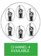
natural_image
Illustration of a row of five identical walkieh machines (no text or symbols visible)Do not place more than seven turned on radios, too close to each other in a container
If the radio is submerged in water,
Turn the radio off and remove the battery

Dry with soft cloth

Do not use radio until it is completely dry
Chapter 3
Battery Features
The radio comes with a rechargeable Lithium-ion (Li-ion) battery. For optimum capacity and performance, ensure your battery is fully charged before first use.
3.1
Battery Specifications
Battery life is determined by several factors. The critical ones are overcharging of batteries and the average depth of discharge each cycle. The greater the overcharge and the deeper the average discharge, the fewer cycles a battery lasts. A battery which is overcharged and discharged 100 % for several times a day, lasts fewer cycles than a battery that overcharges less and is discharged to 50 % per day. Battery with minimal overcharge and has an average of 25 % discharge, lasts even longer.
Motorola Solutions batteries are designed specifically to be used with a Motorola Solutions charger and vice versa. Charging batteries with non-Motorola Solutions equipment may lead to battery damage and void the battery warranty. Whenever possible, maintain the battery temperature to 77 °F (25 °C) (room temperature). Charging a cold battery (below 50 °F [10 °C]) may result in leakage of electrolyte and ultimate failure of the battery. Charging a hot battery (above 95 °F [35 °C]) results in reducing discharge capacity and affecting the performance of the radio. Motorola Solutions rapid-rate battery chargers contain a temperature-sensing circuit to ensure that batteries are charged within the temperature limits.

NOTE: Batteries with different capacities and operational life may be available in the future.
3.2
Motorola Solutions Authorized Batteries
Table 1: Motorola Solutions Authorized Batteries
| Part Number Description |
| HKNN4013_ (BT90) Li-Ion Battery 1800 mAh |
| PMNN4578_ (BT110) Li-Ion Battery 2500 mAh |
3.3
Battery Recycling and Disposal
Lithium-ion rechargeable batteries can be recycled. However, recycling facilities may not be available in all areas. Under various U.S. state laws and the laws of several other countries, batteries must be recycled and cannot be disposed of in landfills or incinerators. Contact your local waste management agency for specific requirements and information in your area. Motorola Solutions fully endorses and encourages the recycling of Lithium-Ion batteries.
In the U.S. and Canada, Motorola Solutions participates in the nationwide Call2Recycle program for battery collection and recycling. Many retailers and dealers participate in this program. For the location of the drop-off facility closest to you, access Call2Recycle website at https://www.call2recycle.org/ or call 1-800-8-BATTERY. The internet site and telephone number also provide other useful information concerning recycling options for consumers, businesses, and governmental agencies.
3.4
Battery Life
The battery life lasts longer when the Battery Save feature is turned on. The Battery Save feature is enabled by default.
Table 2: Battery Life
| Battery Type Battery Life |
| HKNN4013_ (BT90) 11.5 hours |
| PMNN4578_ (BT110) 16 hours |

NOTE: Battery life is estimated based on 5 % transmit, 5 % receive, and 90 % standby standard duty cycle.
3.5
Battery Status
This section provides information on the battery status. The radio can announce the corresponding battery level when you use the Power button to enter the Battery Gauge mode by default.
Table 3: Battery Status
| Battery Status Battery Level Voice Prompt or Tone |
| High 100 % – 71 % “Battery level high” |
| Medium 70 % – 31 % “Battery level medium” |
| Low 30 % – 11 % “Battery level low” |
| Critical 10 % – 0 % “Battery level critical” |
| Shutdown 0 % Shutdown beeps |
Chapter 4
Charging the Batteries
This chapter describes the methods you use to charge your radio.
4.1
Charging a Stand-Alone Battery
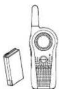
Procedure:
- Align the raised tab on each side of the battery with the corresponding groove on each side of the charger pocket.
- Press the battery toward the rear of the pocket.
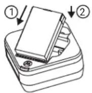

- Slide the battery into the charger pocket, ensuring complete contact between the charger and battery contacts.
When the battery is in the pocket, the charger indicates the Battery Level status as shown in Charger LED Indication on page 20 table. The red LED blinks to indicate that the battery is charging rapidly. The LED changes to a steady green light to indicate that the battery is nearly or fully charged.
4.2
Charging with the Drop-In Tray Single-Unit Charger (SUC)
Prerequisites:

NOTE: Turn off the radio before charging, and fully charge the battery before first use. It is best to charge at room temperature.
Procedure:
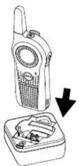
- Place the SUC on a flat surface.
- Insert the connector of the power supply into the SUC port.
- Plug the AC adapter into a power outlet.
- Insert the radio into the SUC with the front of the radio facing the LED of the SUC. Ensure the radio is securely inserted all the way into the charger.
natural_image
Line drawing of a walkie-talkie device with an open case showing internal components (no text or symbols)For more information, see Charger LED Indication on page 20 and Operational Safety Guidelines on page 10
The red LED on the SUC illuminates to indicate that the battery is charging.
4.3
Charging the Radio and the Battery Using a Curve Series 6-Pocket Multi-Unit Charger—Optional Accessory
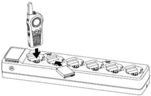
The Curve Series 6-Pocket Multi-Unit Charger (MUC) allows drop-in charging of up to 6 radios or up to 3 radios and 3 stand-alone batteries. The batteries can be charged with the radios or removed and placed in the MUC separately. Each of the six charging pockets can hold a radio (with or without the holster) or battery, but not both at the same time.
Procedure:
- Place the MUC on a flat surface.
- Insert the power cord plug into the MUC dual pin connector at the bottom of the MUC.
- Plug the power cord into an AC outlet.
- Turn off the radio.
- Insert the radio or the battery into the charging pocket with the radio or the battery facing away from the contacts.
natural_image
Line drawing of a walkie-talkie attached to a multi-pin electronic device (no text or symbols visible)Result:

NOTE:
- The MUC clones up to two radios (two source radios and two target radios). For more information, refer to Clone Mode in Multi-Unit Charger on page 89.
- For more information on the MUC operation, refer to the instruction sheets provided with the MUC. For more information on the parts and their part numbers, refer to Accessories on page 101.
4.4
Estimated Charging Time
The following table provides the estimated charging time of the battery. For more information, see Accessories on page 101.
Table 4: Estimated Charging Time
| Charging Solutions Estimated Charging Time |
| HKNN4013_(BT90) 4 hours |
| PMNN4578_(BT110) 5 hours 15 minutes |
4.5
Charger LED Indication
The following table describes the meaning of the charger LED indicator.

NOTE: Ensure the radio or the stand-alone battery is inserted correctly in the charger, and there is power to the outlet.
Table 5: Charger LED Indication
| Indication Status | |
| Green for approximately one second Power On | |
| Solid red Charging | |
| Solid green Charged | |
| Fast blink red Error | 1 |
| Slow blink orange Standby | 2 |
| Blink red one time Battery level is low | |
| Blink orange two times Battery level is medium | |
| Blink green three times Battery level is high | |
Chapter 5
Curve, DLR, and DTR Radios Compatibility
The Curve series radios, DLR, and DTR radios are based on the same digital radio technology and can be used in mixed fleets of the Curve series radios, DLR, and DTR radios. Out of the box, Curve, DLR, and DTR radios communicate using the factory default settings.
If you have DLR or DTR radios with customized settings and/or private groups, and need to add the Curve series radios, use the Curve Series Customer Programming Software (CPS) software ^3 to create a compatible configuration in the Curve Series radios. The same applies if DLR or DTR radios are to be added to an existing Curve Series radio fleet. For more details on Curve Series and DTR compatibility, contact your Motorola Solutions point of sale.
For questions or comments related to this product, contact Motorola Solutions:
• 1-800-448-6866 (North America)
• 1-800-931-855 (Australia)
• 0800-445-227 (New Zealand)
For Latin America, contact the following call center or dealer
• Mexico city : 4738 0332
• Mexico: 01 55 4738 0332
• Brazil: 0800-892-4264
• All other countries: +52 55 4738 0332
Chapter 6
Radio Overview
This chapter explains the buttons and functions to control the radio.
6.1
Radio Controls and Indicators
Figure 1: Curve Controls and Indicators
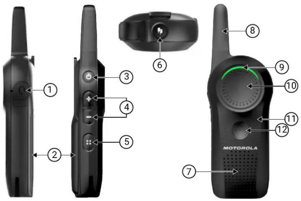
Number Description
1 Audio Accessory Connector
Connects compatible audio accessories.
2 Lithium-ion (Li-ion) Battery
For more information on the battery, refer to Battery Specifications on page 16.
3 Power Button
- To turn the radio On/Off, press and hold the Power button.
- To check the battery status, press the Power button.
- To check Wi-Fi network strength, short press the Power button.
For more information on programming the Power button, refer to step 6 of the Customer Programming Software Basic Menu Instructions on page 81.
Number Description
4 Volume Control Button
● To increase the volume, press the Volume Up button.
- To decrease or mute the volume, press the Volume Down button.
- To cycle through the settings in Programming Mode, press the Volume Up and Volume Down buttons.
- To cycle through the feature settings in User Menu, press the Volume Up and Volume Down buttons.
5 Channel/Menu Button
In standard radio operation mode, the Channel/Menu button is defaulted to channel function.
- To change channels, press the Channel/Menu button.
- To enter the Favorite Contact List (if the Favorite Contact List is not empty), press and hold the Channel/Menu button.
- To browse the channels, press the Volume Up or Volume Down button.
- To navigate through various menus set in the Customer Programming Software (CPS), press the Channel/Menu button.
- To exit, press the PTT button.
In Advanced Configuration Mode, the Channel/Menu button gives access, and allows navigation to set up special features.
6 Top Button
The radio Top button is defaulted to Private Reply feature. For more information on programming the Top button to other features, refer to Special Radio Call Features on page 33.
7 Speaker
8 Antenna
The antenna is non-removable.
9 Tx/Rx Indicator LED
Indicates whether the radio is on standby, receiving, transmitting, scan enable, or Wi-Fi mode.
10 Push-to-Talk (PTT) Button
To talk, press the PTT button and wait to hear the Talk Permit Tone (TPT). The TPT is a quick double beep. Release it to listen.
For more information, refer to Transmitting and Receiving Calls on page 29.
11 Microphone
12 VAB (Voice Assistant Button)
Supports Voice Assistance Application.

NOTE:
Subscription to VAB is required.

NOTE: Wi-Fi and VA features are not available for Latin America.
6.2
Radio Specifications
The radio specification is printed on the back of the radio.
Table 6: Radio Specifications
| Model Frequency Band Transmit Power(Watts) | Number of Channels | Antenna |
| Curve ISM 900 MHz 1 10 Non-removable |
Chapter 7
Getting Started
This chapter describes the basic radio operations.
7.1
Attaching the Battery
Procedure:
- Slide the latch at the top of the battery door to the unlock position, and lift the battery door at the center recess.
a. Align the battery contacts with the tabs in the battery compartment. Insert the contact side of the battery first, then press the battery down to secure in place.
Figure 2: Attaching the Battery
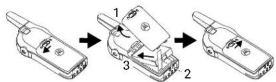
- Put the battery door back on the radio.
- Slide the latch to the lock position.
7.2
Removing the Battery
Procedure:
- Turn the radio off.
- Slide the latch at the top of battery door to the unlock position, and lift the battery door at the center recess.
Figure 3: Removing a Li-Ion Battery
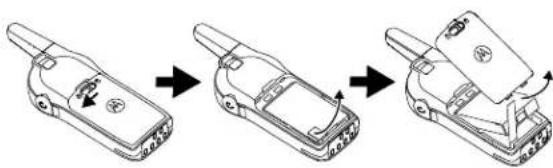
natural_image
Three-step line drawing of a mobile phone device with a handle, showing the process from external to internal components (no text or symbols)- Pull the battery removal tab until the battery is disengaged from the battery compartment.
- Pull the battery away from the radio.
7.3
Attaching the Holster
Figure 4: Holster
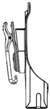
natural_image
Technical line drawing of a mechanical component or bracket (no text or symbols)Procedure:
- To insert the radio into the holster, press the radio against the back of the holster until the hook on the holster is inserted in the top recess.
- To remove the radio from the holster, detach the hook of the holster from the top recess using the top tab, and slide the radio out from the holster.
7.4
Turning the Radio On or Off
Procedure:
- To turn on the radio, press and hold the Power button until the radio plays the power-up tone, and the Tx/Rx LED indicator blinks.
NOTE: By default, when the radio is turned on, it announces the current channel name and battery status. - To turn off the radio, press and hold the Power button until the radio power down tone is heard, and the Tx/Rx Indicator LED indicator turns off.

7.5
Adjusting the Volume
There are 16 increments of volume. When you press the Volume Up or Volume Down buttons, you hear a beep at the current volume level. If your radio is receiving during volume interaction, you hear audio voice prompt from your radio, and the new volume instead of beeps.
Procedure:
- Press the Volume Up button to increase the volume, or the Volume Down button to decrease the volume.
- To mute, press and hold the Volume Down button for two seconds until you hear "Mute" voice prompt from your radio.
- Alternatively, you can mute by pressing the programmable button that is preprogrammed with Mute mode. You hear "Mute" voice prompt from your radio.
- To maximize the volume, press and hold the Volume Up button for two seconds. The volume scrolls up fast to maximum volume. You hear the volume beeps increment as the volume increases.

NOTE:
- Radio mute means setting the volume to the lowest level. This is to prevent the user from forgetting to unmute the radio.
If Silent mode is set as accessory only audio, the tone and audio remains at the lowest volume in radio speaker regardless of the volume button press. Volume for accessory is still configurable through volume buttons.
Do not hold the radio too close to the ear when the volume is high or when adjusting the volume.
When using radio with earpiece, make sure to adjust the radio volume to the lowest volume before putting on the earpiece. For more information, refer to Acoustic Safety on page 11. Use only Motorola Solutions approved accessories. For more information, refer to Accessories on page 101.
7.6
Checking the Battery Status
The battery level status are high, medium, low, and critical.
Procedure:
Press the Power button.
For more information, refer to Battery Status on page 17.
7.7
Checking Wi-Fi Strength Status
Pressing the Power button alternates between announcing the battery status and Wi-Fi strength status.

NOTE:
Wi-Fi feature is not available for Latin America.
Subscription required. Contact your sale representative for more information.
Prerequisites:
- Ensure that your Wi-Fi is enabled.
- Ensure that the Battery & Network Status is selected from the Quick Press On/Off Button Mode dropdown list in the Customer Programming Software (CPS).
Procedure:
-
Press the Power button.
Voice command announces the battery status. -
Press the Power button again.
Voice command announces the network status. The available Wi-Fi strength level and the voice prompts are as follows: "Network Good", "Network Fair", "Network Poor", and "Network Disconnected". "Network Disconnected" is announced when radio is out of range.
Chapter 8
General Radio Operations
8.1
Transmitting and Receiving Calls
Procedure:
- To respond or to talk, press the PTT button.

NOTE: Wait for the Talk Permit Tone (TPT) to end and speak.
A quick double beep is heard.
- Release the PTT button to listen.
Table 7: Tx/Rx LED Indicator
| Indicator Status |
| Slow blinking red The radio is on standby. |
| Solid red The radio is in transmission mode. |
| Fast blinking red The radio is in receiving mode. |
Postrequisites:

IMPORTANT:
Do not release the PTT button at any given time when talking on the radio. Whether you are transmitting using the PTT button or using an in-line PTT on the earpiece accessory, always ensure the PTT button is pressed firmly until the transmission is finished. Releasing the PTT button while transmitting and trying to immediately press the PTT button again causes the radio to sound a loud tone.
Wait for two seconds and press PTT again to continue speaking. If you press the PTT button to transmit and a busy tone is received instead of a TPT, this means the channel is either not available, busy or there are no users reachable within transmission range.
8.2
Talk Permit Tone
Talk Permit Tone (TPT) is a quick distinctive double beep tone that sounds after you press the PTT button, indicating the channel is free to talk.
TPT ensures orderly communications by preventing radios from transmitting over ongoing conversations.

NOTE: To ensure your words are not cut off, wait for the TPT to end and speak.
8.3
Talking to a Group in Channels
Procedure:
To transmit, press the PTT button.

NOTE: Wait for the Talk Permit Tone (TPT) to end and speak.
Solid red Tx/Rx Indicator LED illuminates and the TPT is heard.
8.4
Browsing or Selecting Channels
Procedure:
- Press the Channel/Menu button until you hear "Channel
" voice prompt from your radio. - To select channel, press the Volume Up button or Volume Down button.
You hear the selected channel voice prompt from your radio. - To exit the channel change feature, press the PTT button or wait for the radio Channel/Menu timer to expire.
8.5
Starting Private Reply
The Top button is set to Private Reply feature by default. This feature allows two people to instantly connect privately after a group transmission is over.
Procedure:
- To initiate a Private Reply, press the Top button during a group call.
The Top button LED blinks orange. - After a group call, press PTT button to call privately.
The Top button LED illuminates in solid orange. - Wait for the Talk Permit Tone to end and speak.
8.6
Talk Range
Table 8: Talk Range
| Talk Range | ||
| Model Industrial Multi-Level | ||
| Inside steel/concrete Industrial buildings | Inside multi-level buildings | |
| ISM 900 MHz Up to 300,000 sq. ft Up to 20 Floors | ||
For a group of radio to communicate, all the radios need to be on the same channel and have the same radio PROFILE ID number. The default PROFILE ID number is 0000.
Channel
Current channel that the radio is using, depending on radio model.
PROFILE ID Number
The radio in your fleet, independent of the channels that users are assigned to should use the same PROFILE ID. Customize the PROFILE ID number to avoid interference from other users using the default 0000 number. To customize your radio fleet PROFILE ID, choose a four digit number and enter it using the radio Advanced Configuration Mode. Turn off the radio, press PTT → Volume Up → Power buttons at the same time, and hold until you hear "Programming Mode" voice prompt from your radio. For more information, refer to the Advanced Configuration Mode on page 69.
8.7
Top Button Options
The Top button is programmed to Private Reply feature by default.
You can configure the Top button to other features such as Page All Available, Call Available, Direct Call, and Mute.
For more information on Top button configuration, refer to Advanced Configuration Mode on page 69.
8.8
Radio Status
Table 9: Radio Status
| Radio Status | Front LED Indicator Top Button LED Indicator | Voice Prompt or Tone | |
| Power-Up Solid orange, followed by solid red for two seconds | OFF "Battery Level, Channel" | ||
| Power Off Solid red for two seconds | OFF Power Off chirps | ||
| Fatal Error at Power-up | Double blink red Single blink orange Not Available | ||
| Channel Busy Not available OFF Busy tone | |||
| Idle Mode Slow blink red OFF Not Available | |||
| Transmit (Tx) (standard group call) | Solid red OFF Not Available | ||
| Receive (Rx) (standard group call) | Fast blink red OFF Not Available | ||
| Voice Assistant Tx Solid green OFF Not Available | |||
| Voice Assistant Rx | Fast blink green OFF Not Available | ||
| Voice Assistant Error | Double blink red OFF Not Available | ||
| Radio Status | Front LED Indicator Top Button LED Indicator | Voice Prompt or Tone | |
| Voice Assistant Hang Time | Slow blink green OFF Not Available | ||
| Scan Enable Slower blink green OFF Not Available | |||
| Real Time Alert Fast blink double red, followed by solid green | OFF “Real time alert enabled”“Attention! Attention! A situation required immediate attention!”“Real time alert over” | ||

NOTE: Wi-Fi and VA features are not available for Latin America.
Chapter 9
Special Radio Call Features
This topic explains the radio series special call features.
9.1
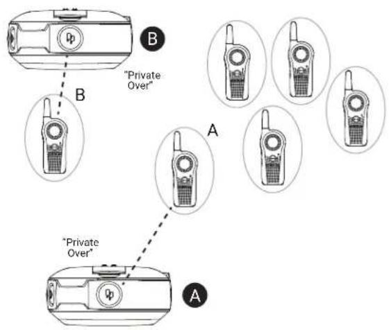
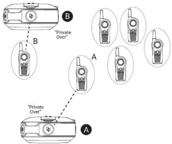
Private Reply
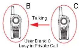
This feature allows two people to instantly connect privately after a group transmission.
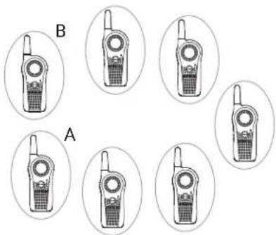
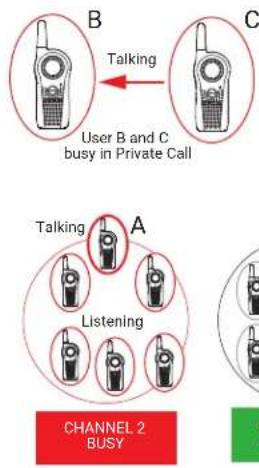
Private Reply Scenario
User B is talking to a group of radios.
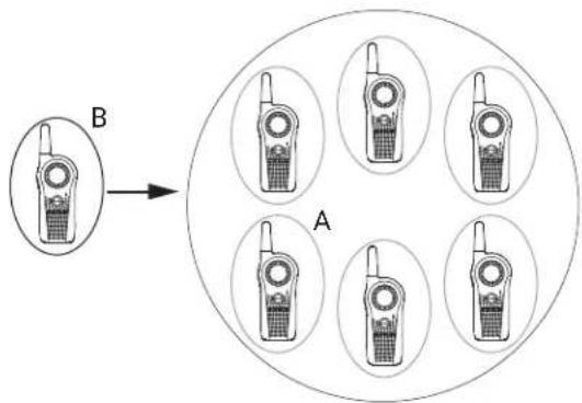
User A wants to talk to User B privately and presses the Top button to queue up.

NOTE: Long pressing the Top button a second time cancels the Private Reply queue.
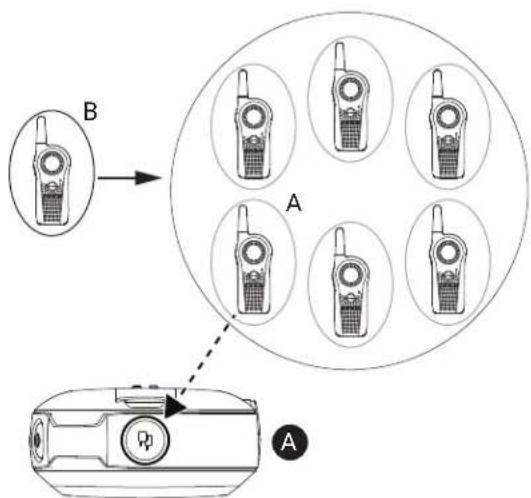
User A radio plays voice prompt "Private Reply" and the Top button starts blinking orange, showing user A is in queue waiting to talk privately to User B.
flowchart
graph TD
    A["Mobile Phone Array"] -->|B| B["Central Circle"]
    B --> C["Radio Station 1"]
    B --> D["Radio Station 2"]
    B --> E["Radio Station 3"]
    B --> F["Radio Station 4"]
    B --> G["Radio Station 5"]
    style A fill:#f9f,stroke:#333
    style B fill:#ccf,stroke:#333
    style C fill:#cfc,stroke:#333
    style D fill:#fcc,stroke:#333
    style E fill:#cff,stroke:#333
    style F fill:#ffc,stroke:#333
    style G fill:#cfc,stroke:#333
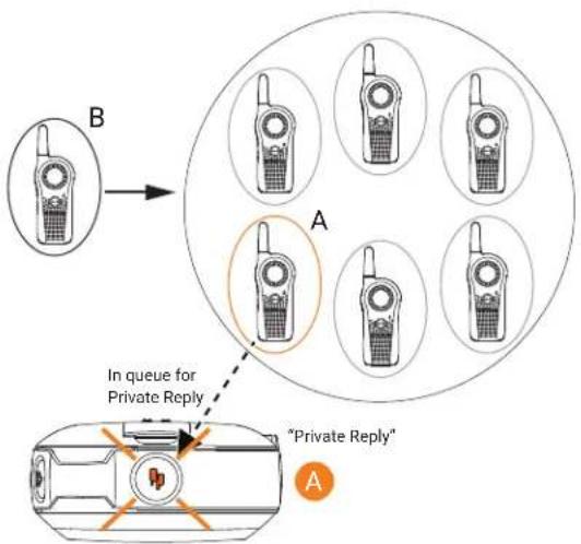
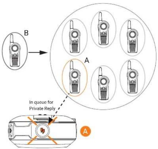
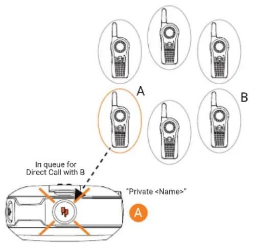
User B finishes talking to the Group while User A radio is still blinking orange indicating it is in queue for Private Reply call.
flowchart
graph TD
    A["In queue for Private Reply"] --> B["Mobile Phone 1"]
    B --> C["Mobile Phone 2"]
    C --> D["Mobile Phone 3"]
    D --> E["Mobile Phone 4"]
    E --> F["Mobile Phone 5"]
    F --> G["Mobile Phone 6"]
    G --> H["Mobile Phone 7"]
    H --> I["Mobile Phone 8"]
    I --> J["Mobile Phone 9"]
    J --> K["Mobile Phone 10"]
    K --> L["Mobile Phone 11"]
    L --> M["Mobile Phone 12"]
    M --> N["Mobile Phone 13"]
    N --> O["Mobile Phone 14"]
    O --> P["Mobile Phone 15"]
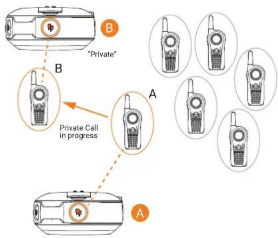
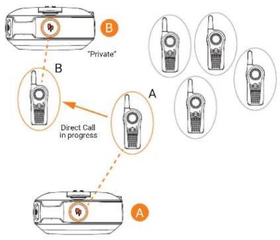
User A presses PTT button to talk privately to User B. The Top button LED indicator for both radio A and radio B illuminate solid orange. User B hears radio voice prompt "Private" and radio plays a distinctive Private Talk Permit Tone (TPT).
flowchart
graph TD
    A["Device B"] -->|Private Call in progress| B["Device B"]
    B --> C["Device A"]
    style A fill:#f9f,stroke:#333
    style B fill:#ccf,stroke:#333
    style C fill:#cfc,stroke:#333
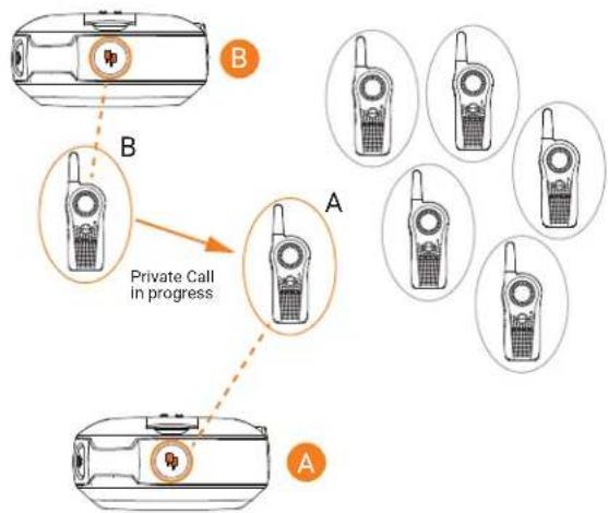
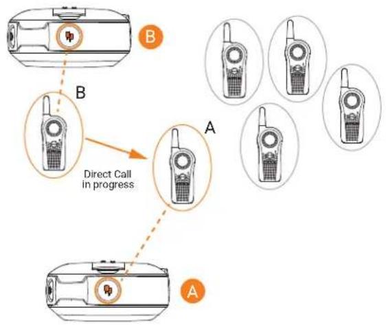
Whenever user A or B presses the PTT button to reply, they are talking privately to each other. Nobody else hears them. Radio plays a distinctive Private TPT.
flowchart
graph TD
    A["Device B"] -->|Private Call in progress| B["Device A"]
    B --> C["Device A"]
    style A fill:#f9f,stroke:#333
    style B fill:#ccf,stroke:#333
    style C fill:#cfc,stroke:#333
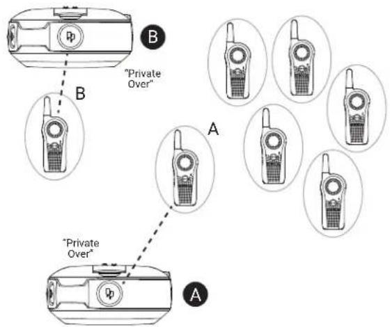
If either one of the radio users takes too long to push the PTT button and reply, the radio times out and ends the private communication with voice prompt "Private Over" on both radios A and B. The Top button LED indicator goes off.

NOTE: The default "Private Hang Time" is 10 seconds.
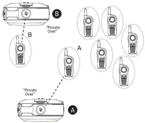
Radio user A who initiated the Private Call, can end the call at any time by long pressing the Top button. The radio plays voice prompt "Private Over" on both radio A and B to indicate that the private call is over. The Top button LED indicator turns off.
Radio users A and B join back the group transmission in their channel once the private call ends.

NOTE: You can set the "Private Hang Time" and "Group Hang Time" to different values using the Customer Programming Software (CPS).
natural_image
Six identical walkieh machines arranged in two rows, labeled A and B, with no visible text or symbols on the devices themselves.9.1.1
Starting Private Reply
This feature allows two people to instantly connect privately after a group transmission. The Top button is programmed by default as Private Reply.
Procedure:
- To capture the radio ID of the person currently talking to your group after transmission is over, press the Top button.
- To initiate the conversation privately, press the PTT button.
9.1.2
Private Reply Status Indicator
Table 10: Private Reply Status Indicator
| Private Reply Status | Radio Caller/Recipient Top Button LED Indicator | Voice Prompt or Tone |
| Private Reply request in queue (initiated using Top button press) | Caller Blink Orange "Private Reply" | |
| Private conversation initiated (using the PTT button) | Recipient Solid Orange "Private TPT" | |
| Private Call notification ^4 | Recipient Solid Orange "Private" | |
| Private conversation in progress | Caller and Recipient Solid Orange "Private TPT" | |
| End of private conversation Caller and Recipient Off "Private Over" | ||
9.2
Direct Call
You can call a pre-determined user programmed in the radio privately. The Direct Call feature is configurable using the Customer Programming Software (CPS).

NOTE: Use the Curve CPS software to configure the Direct Call feature for the first time on your radio. In the United States, Canada, Australia, and New Zealand, you can download for free the Curve CPS Software at http://www.motorolasolutions.com/curve. For Latin America, contact Motorola Solutions Authorized Distributor for CPS information. Read and upload the radio IDs identified as "privates" into the CPS. For more information, refer to Customer Programming Software on page 80.
You have the option to program the Direct Call feature into the Top button, or assign to any radio channel.
Direct Call Scenario
User A presses the radio Top button to talk directly to User B. User A radio plays voice prompt "Private
User A presses the PTT button to talk privately to User B (who is NOT in a radio conversation), the Top button LED indicators of both A & B radios illuminate in solid orange. Radio B plays voice prompt "Private" indicating that the incoming call is a Direct Private Call. Radio plays a distinctive Private Talk Permit Talk (TPT).
flowchart
graph TD
    A["Device 1: "Private""] --> B["Device 2: Direct Call in progress"]
    B --> C["Device 3: "Private""]
    C --> D["Device 4: Direct Call in progress"]
    D --> E["Device 5: "Private""]
    style A fill:#f9f,stroke:#333
    style B fill:#ccf,stroke:#333
    style C fill:#cfc,stroke:#333
    style D fill:#fcc,stroke:#333
    style E fill:#cff,stroke:#333
Whenever either user A or B presses the PTT button to reply, they are talking privately to each other. The radio plays a distinctive Private TPT.
flowchart
graph TD
    A["Device B"] -->|Direct Call in progress| B["Device A"]
    B --> C["Device A"]
    style A fill:#f9f,stroke:#333
    style B fill:#ccf,stroke:#333
    style C fill:#cfc,stroke:#333
If any of the radio users takes too long to push the PTT button and reply, the radio times out and ends the private communication with voice prompt "Private Over" on both radio A and B. The Top button LED indicator goes off.

NOTE: The default "Private Hang Time" is 10 seconds.
Radio User A who initiated the Direct Call, ends the call by long pressing the Top button. The radio plays voice prompt "Private Over" on both radio A and B to indicate that the private call is over. The Top button LED indicator goes off.
Application Example
Set up your employees to be able to contact directly and privately their supervisor, the manager on duty or to reach a designated person for special requests by simply pressing the Direct Call button (Top button) and then pushing the PTT button to talk.

NOTE: If the Direct Call is set up in a specific channel, change to that channel and press the PTT button to talk privately.
9.2.1
Direct Call Status Indicator
Table 11: Direct Call Status Indicator
| Action | Radio Caller/Recipient Top Button LED Indicator | Voice Prompt or Tone |
| Direct Call initiated using Top button. | Caller Blink Orange "<Name of Direct" | Call user>"5 |
| Private conversation initiated using PTT button | Caller Solid Orange "Private TPT" | |
| Private Call notification Recipient Solid Orange "Private" | ||
| Private conversation in progress | Caller and Recipient Solid Orange "Private TPT" | |
| End of private conversation Caller and Recipient Off "Private Over" | ||
9.3
Private Reply and Direct Call Frequently Asked Questions
Table 12: Frequently Asked Questions
| Questions Descriptions | |
| If I change my mind and want to exit the request for Private Call or I pressed the Top button by mistake, how do I get out of the “private queue” status (Radio Top button LED indicator is blinking orange)? | Press and hold the Top button. The radio exits the private queue request and the Top button LED indicator turns off, returning you to the radio normal status. |
| What happens if two people (for example user A and C) press their Top button at the same time to Private Reply or Direct Call User B? | Pressing the Top button only queues the radio B ID. Therefore, there is no issue if two people press the Top button at the same time. The issue occurs when the two people press the PTT button at the same time to talk privately to B. Whoever presses the PTT button faster gets to talk privately to B. The other user hears a “busy” or rejection tone. |
| What happens if a person Private Reply or Direct Call User B, but User B does not want to engage in the Private conversation? | The nature of the radio communication is to allow instant communication without the option to decline radio calls. Therefore, if you are concerned about users disrupting group communications or misusing the Private Reply or Direct Call features, ensure that these features are enabled only on authorized radio users. |
| I pressed the Private Reply button but nothing happened, For example, Top button LED indicator did | It can be due to different causes such as the Top button is disabled or the radio could not store |
| not start blinking and instead the radio gives out a busy tone. | the radio ID you wanted to reply to. This is if the Top button was pressed outside the four seconds Group Hang Time. |
| What happens if I want to Private Reply to a person that just finished talking? | The radios allow for “Group Hang Time” (around four seconds) for you to be able to Private Reply to someone who had just finished talking. Push the Top button within the hang time window and the radio Top button LED indicator starts blinking orange. You can then press the PTT button to talk privately. |
| How does Private Reply work? | When you press the radio Top button while User B is talking, your radio “captures” the ID of radio B. Once user B finished talking and you press the PTT button, your radio calls radio B privately. |
| What happens if I want to end the call during a Private Call or Direct Call conversation? | If you are the user who initiated the Private Reply or Direct Call, you can end the call by long pressing the Top button. However, if you are the call receiver, you have to wait for the radio to time out (no communications detected for more than 10 seconds) or change the channel. |
| I pressed the Top button to queue to talk privately to the last person transmitting, but when the user finished talking and I push the PTT button to talk, the radio gave me a busy tone or other strange tones and I could not initiate my conversation. | It is likely there are other users who were waiting as well to talk to the last person transmitting and someone else pressed the PTT button before you, giving you a busy or error tone. Another reason is that the last person transmitting has gone out of transmission range. |
| If I press the Top button (either for Private Reply or Direct Call) and I forgot that I wanted to talk privately and I did not push the PTT button.● Question: Would I be still able hear the group conversations in my channel if I do not press the PTT button?● Question: How long do I have to talk privately to User B? | There is no time restriction on how long you can take to press the PTT button to talk privately to user A, as long as your Top button LED indicator is blinking. |
| If I press the Top button (either for Private Reply or Direct Call) and I forgot that I wanted to talk privately and I did not push the PTT button.● Question: Does the radio gives me any alert to know that I am in still in the private queue mode? | Yes. While waiting in queue to talk privately, you will receive a call reminder tone after one minute of being in queue, followed by another reminder tone four minutes after that. No other reminder is heard thereafter, but you remain in queue until Private Reply mode is exited. |
| If I press the Top button either for Private Reply or Direct Call and I forgot that I wanted to talk privately and I did not push the PTT button.● Question: How do I respond to group conversation if I have already pushed the Top Button (for either Private Reply or Direct Call) and my Top button LED indicator is blinking? | Press and hold the Top button to exit the private queue mode. The Top button LED indicator turns off. Press the PTT button to reply to the group call. |
| What happens if I am in queue to talk privately (LED indicator blinking orange), then the person that was transmitting finished talking and I press the PTT button to talk but the Top button LED indicator does not change to solid orange? | The radio lets you know you are ready for a private communication by turning the Top button LED indicator to solid orange and playing the voice prompt “private” in the beginning. During the private conversation, it also plays a distinctive Talk Permit Tone. All these different prompts from the radio need to happen to ensure there is a private communication established. If you do not have these prompts, it means that you do not have private communication established and you need to try again. |
| How do I know when the radio is no longer in Private Mode conversation? | You are no longer in a private conversation if the Top button LED indicator is not illuminating solid orange and is either blinking or switched off instead. The radio plays the voice prompt “Private Over”.[TBWA] NOTE: Remember that the Private Reply and the Direct Call time out after 10 seconds of inactivity in which both users are sent back to the group call mode. Radio plays the voice prompt “Private Over” and the Top button LED indicator goes off. |
9.4
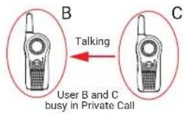
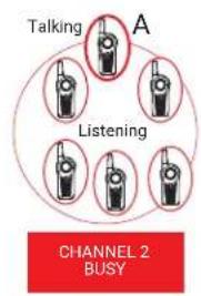
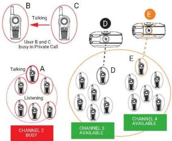
Call All Available
You can perform group call to all users available on different channels, and users who are not in an on-going radio conversation. The Call All Available feature does not interrupt ongoing communications.
You have the option to program the Call All Available feature into Top button, or assign to a channel using the Customer Programming Software (CPS).
The Call All Available feature allows a communication with all available radio users at once in a temporary "super channel" group, without having to change through each channel individually.
When a caller initiate the Call All Available transmission, the Top button is disabled in all radios involved. The Private Reply feature or Direct Call feature is disabled during this period.
The radio times out a Call All Available communication after four seconds of inactivity. The time out prevents all users from being tied up indefinitely in an unnecessary group conversation.
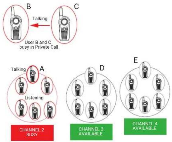
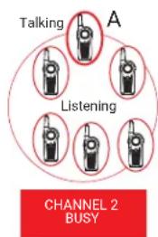
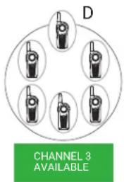
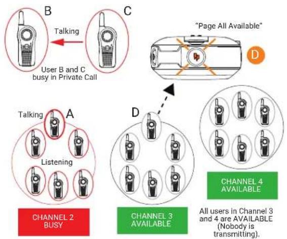
Call All Available Scenario
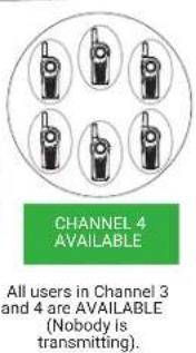
All users in Channel 3 and 4 are available (nobody is transmitting).
flowchart
graph TD
    A["Talking"] --> B["Switch"]
    C["Listening"] --> D["Switch"]
    E["CHANNEL 2 BUSY"] --> F["Switch"]
    G["A"] --> H["Switch"]
    style A fill:#f9f,stroke:#333
    style C fill:#f9f,stroke:#333
    style E fill:#f9f,stroke:#333
    style G fill:#f9f,stroke:#333
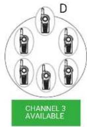
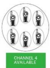
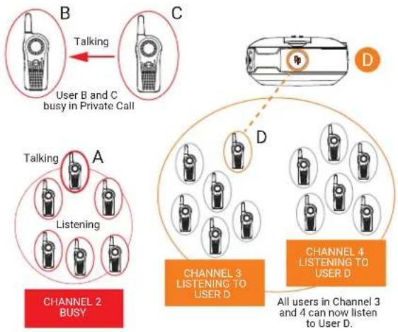
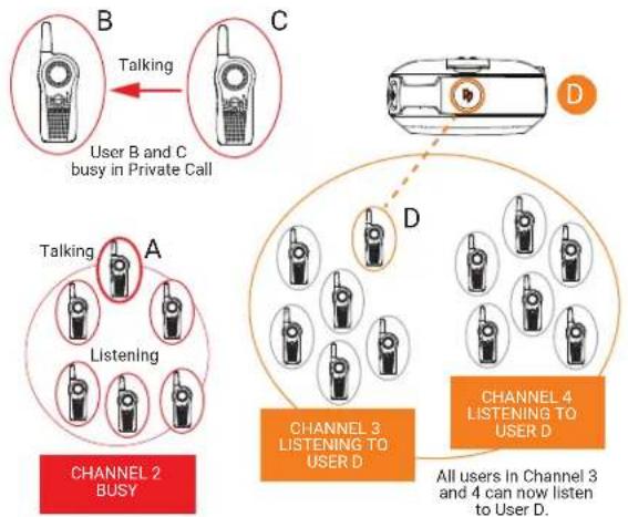
User D in Channel 3 initiates Call All Available by pressing the radio Top button ^6
All users from Channel 3 and 4 are brought into a temporary "super channel" group. User D then presses the PTT button and start talking to all available users in both channels.
flowchart
graph TD
    A["Channel 2 BUSY"] --> B["Talking"]
    B --> C["User B and C busy in Private Call"]
    C --> D["Channel 3 LISTENING TO USER D"]
    D --> E["Channel 4 LISTENING TO USER D"]
    E --> F["All users in Channel 3 and 4 can now listen to User D"]
All radios Top buttons in Channel 3 and 4 are solid orange indicating that Call All Available is in progress.
flowchart
graph TD
    A["User B and C busy in Private Call"] -->|Talking| B["Talking"]
    B --> C["User D continues talking to all available users"]
    C --> D["CHANNEL 2 BUSY"]
    D --> E["Listening"]
    E --> F["CHANNEL 3 LISTENING TO USER D"]
    F --> G["CHANNEL 4 LISTENING TO USER D"]
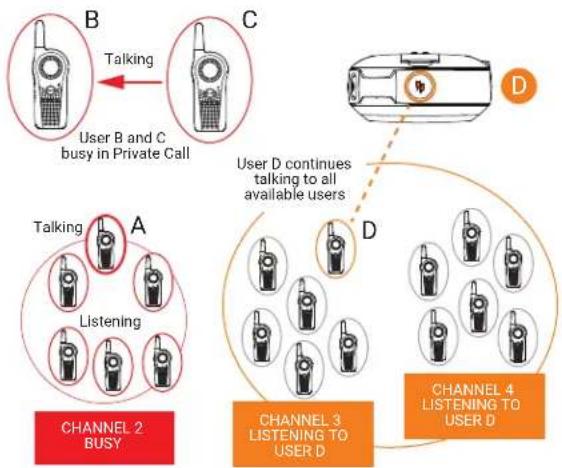
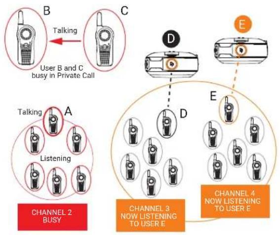
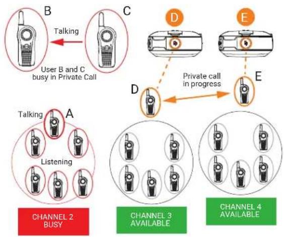
User D finished talking and the Top button LED indicator continue to illuminate solid orange. ^7 User E presses the PTT button and starts talking to all available users. All users in Channel 3 and 4 now hear User E. All radios Top buttons are solid orange indicating that Call All Available is in progress.
flowchart
graph TD
    subgraph Channel 2
        B["User B and C busy in Private Call"]
    end

    subgraph Channel 3
        D["User B and C busy in Private Call"]
        E["User B and C busy in Private Call"]
    end

    subgraph Channel 4
        D --> E
        E --> D
        D --> E

    B -->|Talking| C
    C -->|Dotted Line| D
    D -->|Dotted Line| E

    subgraph Channel 2 BUSY
        A["Listening"] --> B
    end

    subgraph Channel 3 NOW LISTENING TO USER E
        D --> E
    end
Once all users finished communicating (no transmissions for more than four seconds), the radios time out and end the Call All Available "super channel" group. All users in channel 3 and 4 return to their original talk channels.
flowchart
graph TD
    A["User B and C busy in Private Call"] -->|Talking| B["Talking"]
    B --> C["Listening"]
    C --> D["CHANNEL 2 BUSY"]
    C --> E["CHANNEL 3 AVAILABLE"]
    E --> F["CHANNEL 4 AVAILABLE"]
Application Example
An employee in a retail shop uses the radio with the Top button programmed to Call All Available. This employee is trying to check if anyone took the back room scanner. The employee presses the Top button followed by the PTT button and asks "Does anybody know who has the backroom scanner?". Anyone, irrespective of their channel, who is not already part of another conversation, hears this call and can talk back to the whole group of users (who are tied up in the super channel group call) and provide the needed information.
9.4.1
Call All Available Status Indicator
Table 13: Call All Available Status Indicator
| Action | Radio Caller/Recipient Top Button LED Indicator | Voice Prompt or Tone |
| Call All Available initiated using Top button | Caller Blink Orange “Call All Available” | |
| Call All Available conversation initiated using PTT button | Caller Solid Orange Standard TPT | |
| Call All Available call notification | Recipient Solid Orange Standard TPT | |
| Call All Available conversation in progress | Caller and Recipient Solid Orange Standard TPT | |
| End of Call All Available Caller and Recipient Off None | ||
9.5
Page All Available
You can communicate with all available radio users at once without having to change through each channel individually. The Page All Available feature does not interrupt ongoing communications.
You have the option to program the Page All Available feature into Top button, or assign to a channel using the Customer Programming Software (CPS).
The Page All Available feature is a one-way group voice announcement to all users on different channels who are not in an ongoing radio conversation. It prevents users from getting in an unwanted ongoing group conversation.
Page All Available Scenario
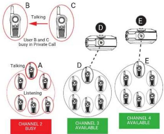
All users in Channel 3 and 4 are available (nobody is transmitting).
flowchart
graph TD
    A["Talking"] --> B["Person"]
    C["Listening"] --> D["Person"]
    E["CHANNEL 2 BUSY"] --> F["Person"]
    G["A"] --> H["Person"]
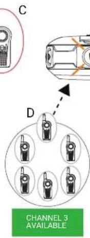
User D in Channel 3 initiates Page All Available by switching to Channel 6 ^8 .
flowchart
graph TD
    A["User B and C busy in Private Call"] -->|Talking| B["Call icon"]
    B --> C["Page All Available"]
    C --> D["Channel 2 BUSY"]
    D --> E["Listening"]
    E --> F["Channel 3 AVAILABLE"]
    F --> G["Channel 4 AVAILABLE"]
    G --> H["All users in Channel 3 and 4 are AVAILABLE (Nobody is transmitting)."]
All users from Channel 3 and 4 are brought into a temporary "super group". User D then presses the PTT button and starts talking to all available users in both channels.
flowchart
graph TD
    A["User B and C busy in Private Call"] -->|Talking| B["Talking"]
    B --> C["Channel 2 BUSY"]
    C --> D["Listening"]
    D --> E["Channel 3 LISTENING TO USER D"]
    E --> F["Channel 4 LISTENING TO USER D"]
    F --> G["All users in Channel 3 and 4 can now listen to User D"]
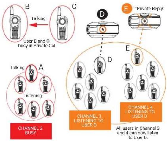
User D continues talking to all available users. User E wants to reply to user D and presses the Top button ^9 . User E goes in queue for Private Reply.
flowchart
graph TD
    A["Channel 2 BUSY"] --> B["Talking"]
    B --> C["User B and C busy in Private Call"]
    C --> D["Channel 3 LISTENING TO USER D"]
    D --> E["Private Reply"]
    E --> F["Channel 4 LISTENING TO USER D"]
    F --> G["All users in Channel 3 and 4 can now listen to User D"]
Once user D stops transmitting by releasing the PTT button, the Page All Available is over. All users in Channel 3 and 4 are back to their original channel groups. User E remains in queue for Private Reply.
flowchart
graph TD
    A["User B and C busy in Private Call"] -->|Talking| B["Talking"]
    B --> C["Listening"]
    C --> D["CHANNEL 2 BUSY"]
    D --> E["CHANNEL 3 AVAILABLE"]
    E --> F["CHANNEL 4 AVAILABLE"]
    style A fill:#f9f,stroke:#333
    style B fill:#ccf,stroke:#333
    style C fill:#cfc,stroke:#333
    style D fill:#fcc,stroke:#333
    style E fill:#cff,stroke:#333
    style F fill:#ffc,stroke:#333
User E presses PTT to talk to user D. They are now engaged in a Private Conversation. Nobody else can hear them. The Top button LED indicator for radio D and E illuminates solid orange.
flowchart
graph TD
    A["User B and C busy in Private Call"] -->|Talking| B["Talking"]
    B --> C["CHANNEL 2 BUSY"]
    C --> D["Listening"]
    D --> E["CHANNEL 3 AVAILABLE"]
    E --> F["CHANNEL 4 AVAILABLE"]
    F --> G["CHANNEL 4 Available"]
    style A fill:#f9f,stroke:#333
    style B fill:#ccf,stroke:#333
    style C fill:#cfc,stroke:#333
    style D fill:#fcc,stroke:#333
    style E fill:#cff,stroke:#333
    style F fill:#ffc,stroke:#333
    style G fill:#cfc,stroke:#333
Once User D and E finish the private conversation, they are returned to their respective group channel. The Top button LED indicator both radios switched off.
flowchart
graph TD
    A["User B and C busy in Private Call"] -->|Talking| B["Talking"]
    B --> C["Listening"]
    C --> D["CHANNEL 2 BUSY"]
    D --> E["CHANNEL 3 AVAILABLE"]
    E --> F["CHANNEL 4 AVAILABLE"]
Application Example 1
An employee in a retail shop uses the radio with the Top button programmed to Private Reply and Channel 6 programmed to Page All Available feature. This employee is looking for anyone in any of the group radio channels who can come over to help out in the back room. The employee changes to the Page All Available channel before pressing the PTT button and asks "Can someone come over to the back room to help out?". Whoever is available in any of the radio channels can privately reply to the employee to ask for more details or to confirm that they are available to help.
Application Example 2
Anna needs to talk privately to another user (John) and she is not sure in which channel to find him. It is cumbersome to browse all channels to search for John. Anna uses the radio with the Top button programmed to Private Reply and Channel 6 programmed to Page All Available feature. She switches to Channel 6 and asks "John Smith, are you available?"
If John is available, he can reply privately (by pressing the Top button). If no response is heard, it means that he is busy in another radio call or is not within the communication range.
9.5.1
Page All Available Status Indicator
Table 14: Page All Available Status Indicator
| Action | Radio Caller/Recipient Top Button LED Indicator | Voice Prompt or Tone |
| Page All Available initiated using Top button | Caller Blink Orange “Page All Available” | ble” |
| Page All Available conversation initiated using the PTT button | Caller Solid Orange Standard TPT | |
| Page All Available Call notification | Recipient Solid Orange Standard TPT | |
| Page All Available conversation in progress | Caller and Recipient Solid Orange Standard TPT | |
| End of Page All Available Caller and Recipient Off None | ||

NOTE:
To initiate Page All Available, press the Top button or change to a channel that is preset to Page All Available followed by the PTT button to talk to all available users in different channels.
The Top button must be pre-programmed to Page All Available through advanced configuration or Customer Programming Software (CPS). The only way to respond to someone doing a Page All Available call is by Private Reply. Page All Available can also be programmed to a radio channel.
For more information, refer to Customer Programming Software on page 80.
Chapter 10
Advanced Features
This topic explains the advanced features for Curve series radios.
10.1
Voice Assistant Mode Features
Voice Assistant Button (VAB) enables the user to initiate connection to the Curve Portal through Wi-Fi.

NOTE:
- Voice Control Command is only supported in English only.
- The Voice Assistant Button (VAB) and the VA features are not available for Latin America.
You can perform the following actions while holding the VA button:
- Logging in to the Curve Portal
- Logging out from the Curve Portal
- Sending and playing back voice messages
- Triggering voice calls.

NOTE:
- You must pre-configure all Voice Assistant features in the Curve Portal before you can use these features on the radio.
- Subscription required. Contact your sales representative for more information.
For Curve Portal usage, refer to Curve Radio Business Portal User Guide (MN008507A01) at https://learning.motorolasolutions.com
Table 15: Voice Control Command
| Voice Assistant Mode Examples | |
| Voice Login | Say one of the following commands:“log in, pin”“log on, pin”“sign in, pin”“sign on, pin” |
| Voice Logout | Say one of the following commands:“log out”“log off”“sign out”“sign off” |
| Direct Call | Say one of the following commands:“Call”“Contact”“Call”“Contact” |
| Record Voice Message | Say one of the following commands:“Record message for”“Send message to” |
| Play Voice Message | “Play Message” |
| Play Store Wide Announcement | |
| Join Group | “Join” |
| Send message to Group | “Send message to” |
| Leave Group | “Leave” |
| Send Store Wide Announcement “Send announcement” | |
10.1.1
Voice Assistant Mode Indicators
Table 16: Voice Assistant Mode Indications
| Radio Status Front LED Voice Prompt or Tone | ||
| VAB HangTime | Slow blink green N/A | |
| VAB Tx Solid green Voice Control ready tone. | ||
| VAB Rx Fast blink green VAB responses. | ||
| Wi-Fi connection error during VAB use | Double blink red | Busy tone while the VAB button is pressed.When the VAB is released, "Connecting to Wi-Fi, please try again". |
| Wi-Fi status switches from disconnected to connected | N/A "Wi-Fi connected" | |
| Wi-Fi status switches from connected to disconnected | N/A "Wi-Fi disconnected" | |
10.1.2
Subscription Activation for Motorola Solutions Voice Assistant Services
Wi-Fi-enabled Voice Assistance is available with Curve through subscription. Contact your approved Motorola Solutions Distributor or Reseller to arrange, or visit http://www.motorolasolutions.com/curve for more information.

NOTE: Wi-Fi and Voice Assistant features are not available for Latin America.
10.1.3
Virtual Channel
The Virtual Channel feature allows you to dynamically add another channel onto your radio when it is active. After you have login to EVA mode, you can configure the virtual channel with a public group. The virtual channel is indicated by the voice prompts "Virtual Channel
The user is only attached to a public group when the user is logged in. If the user logs out, the user will be detached from the group. To reattach to the group, the user needs to re-trigger the targeted group's Join Group command.
When activated, the virtual channels is placed in between the first and last enabled channels. For example, if the radio only enabled 3 channels, then the selection sequence are as follows: Channel 1 → Channel 2 → Channel 3 → Virtual Channel 1 → Channel 1.
In the User Menu, if user customized voice prompt is not defined for the channel, when the user navigates from Virtual channel to Channel, radio plays "Channel

NOTE:
The virtual channel is removed after you turn the radio off. Radio-triggered resets do not deactivate the Virtual Channel from the radio.
If the radio is in a virtual channel before the radio turns off and the home channel is not set, powering up the radio initiates the radio with the next enabled channel.
10.1.3.1
Joining Virtual Channel
Prerequisites: Ensure that you are login to Voice Assistant mode before joining a specific group.
Procedure:
- Press and hold the VAB button.
- After you hear a tone and the front LED shows solid green, speak "join
" into the microphone. - Release the VAB button.
- Perform the following choices based on response from the voice command.
| If voice command responds with... then, you... | |
| "Joined Group" No response is required from you. Radio exitsWi-Fi mode and is now in the virtual channel. | |
| "Did you mean?"NOTE: Voice command provides first four potential matches. | press the VAB button to reply "Yes" or "No"release the VAB button.NOTE:If your response is "Yes", the voice command responds "". Follow the choice for the voice command response.If you response is "No" and there are no more potential matches, voice command responds "Groupnot found". Follow the choice for the voice command response. |
| "Groupnot found" | Ensure that the group name is valid and preconfigured in the Curve Portal. Repeat step 1 through step 4. |
| "User login required" Login to EVA mode. | |
After you have logged in and joined a group, press the VAB button. The voice command responds with "
10.1.3.2
Leaving Virtual Channel
Prerequisites: Ensure that you are login to Voice Assistant mode before playing a voice message.
Procedure:
- Press and hold the VAB button.
- After you hear a tone and the front LED shows solid green, speak "leave
" into the microphone.
The command "leave
- Release the VAB button.
- Perform the following choices based on response from the voice command.
| If voice command responds with... then, you... | |
| "left Group"No respond required from you. | No respond required from you. |
| "Did you meanNOTE: Voice command provides first four potential matches. | press the VAB button to reply "Yes" or "No"Release the VAB button.NOTE:If your response is "Yes", the voice command responds "left group" available.Follow the choice for the voice command response.If your response is "No" and there are no more potential matches, voice command responds "groupnot found". Follow the choice for the voice command response. |
| "Groupnot found" | press the VAB button to reply with a group name that was preconfigured in Curve Portal.release the VAB button. |
| "User Login is required" login to EVA mode. | |
| "not in any groups" No response is required | from you. If there are any virtual channels on the radio, the virtual channels are deleted. |
The following scenarios allows you to leave the group:
- Radio powering down.
- Triggering leaving group through EVA.
- Log out
- Relogin with the same or different user.
10.1.4
Best Practices When Using Voice Assistant Features
Perform the following best practices for optimum use of the Voice Assistant feature in a noisy environment or when you encounter voice recognition issues:
- Without accessories: Bring the radio close to your mouth with the microphone facing your mouth. The recommended distance is two-inch.

natural_image
Simple line drawing of a person holding a mobile phone with sound waves (no text or symbols)- With wired accessories: Bring the in-line mic close to your mouth with the microphone facing your mouth. The recommended distance is two-inch.

natural_image
Line drawing of a person holding a medical device with earphones (no text or symbols)10.1.5
Voice Assistant Feedback Error Definition
Table 17: Voice Assistant Feedback Error Definition
| Error Feedback Error and Possible Solutions | |
| "Not Found" | Group is not imported into the Curve Portal. Ensure that the requested group is imported into the Curve Portal. |
| "User login is required" | Radio must logged in successfully before performing any Voice Assistance (VA) commands. |
| "Not In Any Groups" | Radio is not attached to the group. |
| "Connecting to Wi-Fi, please try again" | Radio is not connected to the Wi-Fi router. Perform one of the following solutions:Ensure that the Wi-Fi SSID, password, and security type are correct.Ensure that the radio is within Wi-Fi coverage.Radio is busy. Wait for 15 seconds and press the VAB button again. |
| "System error. Please try again" | Radio is not connected to the server. Perform one of the following solutions:Ensure that the Site ID is set and correct.Radio is busy. Wait for 15 seconds and press the VAB button again. |
| Single bonk | The radio plays a single bonk to alert the user that the user pressed an unsupported button in VA mode, such as the Menu button and Top button. |
| Radio is busy and failed to establish a new connection with the server. Perform one of the following solutions:Press the PTT button to exit VA mode, or | |
| Wait for a few seconds before pressing the VAB button. | |
| Double bonk | Radio does not receive response from the server within the allocated response time. This error happens after the user has completed a voice command and release the VAB button.Ensure that your network status is good. Try sending voice command and release the VAB button. |
| The radio is busy when the user press and release the VAB button. Perform one of the following solutions:Press the PTT button to exit VA mode, orWait for a few seconds before pressing the VAB button. | |
| Talk prohibited tone (while holding the VAB button. | Radio is busy when user press and hold the VAB button. This error happens immediately when you press and hold the VAB button.Perform one of the following solutions:Press the PTT button to exit VA mode, orWait for a few seconds before pressing the VAB button. |
| Radio encounters error to transmit voice command to the server. The server does not process partially completed voice caused by a sudden error. This error occurs more than 10 seconds after you press and hold the VAB button.Perform one of the following solutions:Network status is weak. Move nearer to the Wi-Fi router.Internet speed is too slow. Upgrade your internet speed or switch to another internet source. | |
| User press and hold the VAB button for more than two minutes (exceeded the maximum voice command or voice message length). Radio transmits the two minutes voice command or voice message to the server.Release the VAB button. | |
10.1.6
Voice Assistant Message Query
Voice Assistant (VA) Message Query allows the radio to send a periodic query to the VA to check whether or not you have any pending voice message. A voice message chirps when there is a new message available and exits Wi-Fi mode.
To enable this feature, you must set the VA Message Query interval in Customer Programming Software (CPS). The default value for the interval is 5 minutes.

NOTE:
VA Message Query is disabled if the Enable Wi-Fi checkbox is disabled regardless of the VA Message Query interval settings. This feature only works in Idle mode.
10.1.7
Login and Logout of Voice Assistant Mode
Procedure:
Perform one of the following actions based on your preference:
| Option Actions | |
| Logging In through voice | a. Press and hold the VAB button.b. After you hear a tone and the front LED shows solid green, speak your request into the microphone.c. Release the VAB button.d. If login is successful, a voice command responds “<username> logged in”. |
| Logging In through Kiosk | a. Go to Curve Kiosk.b. Press and release the VAB button on your radio. A voice respond speaks out your radio passphrase.c. Type your address book name.d. Type your PIN.e. Select your radio passphrase from the drop-down list. Use the passphrase provided by the voice respond from step b.f. If login is successful, a voice command responds “<username> logged in”. |
10.1.8
Logout of Voice Assistant Mode
Procedure:
- Press and hold the VAB button.
- After you hear a tone and the front LED shows solid green, speak your request into the microphone.
- Release the VAB button.
- If logout is successful, the voice command responds "
logged out, goodbye".
The user is automatically log off from the Curve Portal in the following scenarios:
- Radio automatically power off because battery is low.
- User manually switches off the radio or remove the battery.
- Radio automatically powered off when it returns to the charger.
10.1.9
Making Direct Call in Voice Assistant Mode
Procedure:
- Press and hold the VAB button.
- After you hear a tone and the front LED shows solid green, speak your request into the microphone.
- Release the VAB button.
- Perform the following choices based on response from the voice command.
| If voice command responds with... then, you... | |
| “, private call available”NOTE: The top button LED blinking orange continuously if successfully queue the VA direct call.“, available” and followed by the top button LED blinks according to current DLR group call behaviour. | press the PTT button to initiate call in LMR mode.NOTE:Direct call for group name is limited to Public Group 21–Public Group 100.Group name must match the group name in Curve Portal. |
| “is offline” no response is required from you. The user is offline. | |
| “Did you mean?”NOTE: Voice command provides first four potential matches. | press the VAB button to reply “Yes” or “No”.release the VAB button.NOTE:If your response is “Yes”, the voice command responds “available”. Follow the choice for the voice command response.If your response is “No” and there are no more potential matches, Voice command responds ”not found”. Follow the choice for the voice command response. |
| “not found” no response is required from you. The user is not in database. |
-
To cancel call queue and to enter Voice Assistant mode, press and hold the VAB button.
-
To cancel private call and return to the LMR idle mode, press and hold the programmable button.
10.1.10
Recording Voice Message
Prerequisites:
- Ensure that you're login to Voice Assistant mode before recording a voice message.
- If you want to record a message for a group, ensure that you are logged in and joined a valid group.
Procedure:
- Press and hold the VAB button.
- After you hear a tone and the front LED shows solid green, speak your request into the microphone.
- Release the VAB button.
- If the user is found in the database, the voice command responds "
ready". For Store Wide Announcement, the voice command responds "ready". - Press the VAB button and speak the voice message immediately. Otherwise, the recording fails.

NOTE: Maximum length of voice is 2 minutes.
-
Release the VAB button.
-
Perform the following choices based on response from the voice command.
| If voice command responds with... then, you... | |
| "Message sent to" | no response is required from you. Your message is sent and disconnected from the Voice Assistant Gateway. |
| "Did you mean?"NOTE: Voice command provides first four potential matches. | press the VAB button to reply "Yes" or "No".release the VAB button.NOTE:If your respond is "Yes", the voice command responds "ready". Follow the choice for the voice command response.If you respond is "No", voice command responds "Did you mean?". Follow the choice for the voice command response. |
| "not found" | no response is required from you. The user is not in database. |
| "Sorry, I didn't get that. Please respond with yes or no." | press the VAB button to reply "Yes" or "No".release the VAB button. |
| "Announcement sent" No response is required from you. Store Wide Announcement sent. | |
| "User login required" Login to EVA mode. | |
| "mailbox full" No response | is required from you. Recipient must clear the mailbox. |
10.1.11
Playing and Ending Voice Message
Prerequisites:
- Ensure that you are login to Voice Assistant mode before playing a voice message. A voice message chirps when there is a new message available.
- If you are playing a voice message from a group, ensure that you joined a valid group.
Procedure:
-
Press and hold the VAB button.
-
After you hear a tone and the front LED shows solid green, speak "play message" into the microphone if you are playing voice messages.
-
Release the VAB button.
-
Perform the following choices based on response from the voice command.
| If voice command responds with... then, you... | |
| "You haveof new messages. New messages from,repeat, delete or next message?" "You haveof old messages. Old messages from,repeat, delete, or next message?" "You have 1 new message. New messages from,repeat or delete?" "Sorry, I did not get that, you can say repeat, delete, or next, message" | press the VAB button to reply "Repeat", "Delete", or "Next Message".release the VAB button. |
| "User login required" Login to EVA mode. | |
| "You have no messages. Ending call." "You have no announcements. Ending call." | No response is required from you. |

NOTE:
- If you leave a group, any unread messages for that group is removed from the users mailbox.
- If you leave a group, any read messages for that group is still available for replays.
- If you rejoin a group, any unread group messages is added into your mailbox.
- If there is any unread messages, Store Wide Announcement message is played first before group or individual messages.
- You can set the timeout timer for group message and Store Wide Announcement in the Curve Portal. You can set 1 to 10 hours for group message and 1 to 23 hours for Store Wide Announcement. After timeout, the messages is permanently deleted.
10.2
Auto Power off Features
Auto Power Off (APO) feature allows the radio in User mode to power off automatically after a specific delay duration from the moment the radio is plugged into a charger where the power socket is switched on. This feature available by default with a 180 seconds of delay duration. Contact your dealer if you need to reconfigure the timer for the APO feature or to turn off this feature.
APO feature is disabled for the radios that are in the following scenarios:
- Programming Mode
- Test Mode
- Clone Mode
- Return to User mode after CPS performed read or write
- Completed cloning
- Programming mode by software reset
You must turn the radio off and on manually by pressing the Power button to enable the APO after the scenarios.
10.2.1
Initiating Auto Power Off
Prerequisites:
- This feature is turned on by default in CPS with a 180 seconds of delay duration.
- If you have performed cloning or your radio is in Programming mode or Test mode, you must turn your radio off and on.
Procedure:
- Plug in your radio to a single-unit charger (SUC) or a multi-unit charger (MUC).
- Turn on the power socket.
- Ensure that your radio is in User mode.
Do not remove the radio from the charger. Removing the radio while the APO timer is running causes the timer to stop abruptly and the radio do not power off automatically.
Result: Radio powers off automatically after the Auto Power Off timer runs out. Power Off tone is played.
10.3
Scan
The Curve series radio supports scan feature. When the radio detects activity, it stops scanning and locks in on the active channel. This allows you to listen and talk to the person transmitting without changing channels.
Depending on the selection you configured in CPS and based on the hopset of the current channel, you can scan either for "Public Group and Private Group" or scan for "Public Group Only".

NOTE: All Private Groups that your radio is a member are scanned. You cannot choose the groups to be scanned.
10.3.1
Enabling or Disabling Scan
Prerequisites: You must configure the CPS to enable the Scan menu before Scan can be used in the radio menu.
Procedure:
- Press the Menu button to navigate through the various menu.
Upon entering the Scan menu, you hear "Scan mode disable", "scan mode enable", or "To change, press plus or minus".
- Press Volume Up or Volume Down button to enable or disable scan mode.
10.3.2
Scan Status Indicator
Table 18: Scan Status Indicator
| Radio Status Front LED Voice Prompt or Tone | ||
| Scan | Slower blink green | N/A |
| Receive during scan Fast blink red N/A | ||
10.4
Favorite Contact List
The Curve series radio has Favorite Contact List feature. Scan and Receive calls are not allowed in Favorite Contact List Menu. The radio terminates any receive or hangtime modes, stops scanning, and return the base mode to idle state when entering Favorite Contact List Menu.
To use Favorite Contact List, you must add contact into Favorite Contact in Customer Programming Software (CPS) first.
10.4.1
Entering Favorite Contact List Menu
Procedure:
- Press and hold the Menu in the User Mode.
If the list is empty, the radio plays a bad bonk tone. If the list is not empty, the radio enters into the Favorite Contact List Menu.
- Press Volume Up or Volume Down button to select the
.
You can hear voice prompt of the current favorite contact when scrolling the list.
- Press the PTT button to initiate a Private Call.
10.4.2
Exiting Favorite Contact List Menu
Procedure:
To exit Favorite Contact List Menu, choose from:
- press and hold the Menu button, or
- wait for the timer to expire.
Radio plays the Menu Exit tone.
10.5
Real Time Alert
Real Time Alert feature enables you to send distress signals to all available radios.
To enable the feature, configure the programmable button to function as a Real Time Alert using the Customer Programming Software (CPS).
You can confirm if the Top button is configured for the Real Time Alert feature by shortly pressing the Top button. You hear a "Real Time Alert enabled" voice prompt from your radio confirming the current configuration.
When the radio is in the Real Time Alert mode, you can receive the Call All Public Group only. You can communicate with other radios by pressing the PTT during the Real Time Alert hang time. The radio sounds the Talk Permit Tone when the radio is transmitting.
10.5.1
Transmitting Real Time Alert
Procedure:
To send the Real Time Alert, long press the Top button.
Your radio shows the following indications:
- The radio enters the Real Time Alert mode and transmits three cycles of alert.
- The LED blinks double red, followed by solid green.
The radio sounds a bad bonk when you press the Top button, EVA button, or the Menu button indicating you are not able to execute these features.
10.5.2
Receiving Real Time Alert
When you receive a Real Time Alert, your radio enters the Real Time Alert mode and shows the following indications:
- The radio sounds a Real Time Alert tone.
- You hear "Attention! Attention! A situation requires immediate attention!" voice prompt from your radio.
● The LED blinks double red, followed by solid green.
The radio sounds a bad bonk when you press the Top button, EVA button, or the Menu button indicating you are not able to execute these features.
When you receive the cancellation of Real Time Alert, the receiver radio exits Real Time Alert mode and you hear "Real Time Alert over" voice prompt.
10.5.3
Canceling Real Time Alert
Procedure:
To cancel the Real Time Alert, press and hold the Top button.
Radio exits the Real Time Alert mode and returns to the idle state.
You hear "Real Time Alert over" voice prompt from your radio.

NOTE: Real Time Alert is automatically canceled after the radio sends out the three cycles of alert.
10.6
Task Reminder
The Task Reminder feature allows you to set up a reminder timer on the radio. When the time expires, the radio emits a continuous tone to alert you.
The Task Reminder Timer Interval field is visible and is configurable using the Customer Programming Software (CPS). The following table lists the available timer interval options and the reminder timer options:
Table 19: Task Reminder Timer Interval
| Task Reminder Timer Interval (Minutes) Reminder Timer Options (Minutes) |
| 5 (Default) Disabled, 5, 10, 15, 20, 25, and 30 |
| 10 Disabled, 10, 20, and 30 |
| 15 Disabled, 15, and 30 |
The interval options begin with Disabled and increase according to the selected timer interval up to a maximum duration of 30 minutes.
10.6.1
Enabling or Disabling Reminder Timer
Prerequisites: Configure the Task Reminder timer using Customer Programming Software (CPS) and enable the feature.
Procedure:
- To navigate through various menus, press the Menu button.
Upon entering the Task Reminder menu, you hear "Reminder disabled" or "Reminder
- Press Volume Up or Volume Down button to navigate through the reminder timer options.
You can hear the voice prompt of the current reminder timer options when scrolling the list.
Selecting any option for the reminder timer other than Disabled activates the timer immediately.
10.6.2
Reminder Timer Expires
The reminder timer feature is available when the radio is in the user mode and idle state.
The reminder tone sounds when the radio reaches the set time on the reminder timer. The radio plays the reminder tone continuously until it is interrupted or you manually turn off the feature.
Short pressing the Power button stops the reminder tone and you hear "Reminder disabled".
The reminder tone repeatedly snoozes for 30 seconds before being replayed if the following conditions are met when the timer expires:
- Pressing any buttons other than the Power button.
● Receiving a voice or data call. - Receiving a request to enter test mode.
- Another tone or voice prompt is about to play.

NOTE: If the Beeps field is disabled in the Customer Programming Software (CPS), the reminder tone continues to play when the reminder timer expires.
10.6.3
Curve Portal Intelligent Insight
The Intelligent Insight feature in Curve Portal allows you to track the usage of task reminders in your location.
You must activate the Wi-Fi and Intelligent Insight options in Customer Programming Software (CPS), under the Cloud Settings (Basic) section to enable the feature.
When intelligent insight is enabled on a Curve radio, every use of a task reminder on the radio is recorded. The insight data is sent to the cloud server every 60 minutes or upon power on.
Navigate to the Intelligent Insight in Curve Portal to view the usage of task reminder. The frequency of task reminder usage in different time frames is displayed in a chart.
Figure 5: Menu Task Reminder

bar
Menu Task Reminder | Time | Total Counts | |---|---| | 11:00 AM | 0 | | 12:00 PM | 0 | | 1:00 PM | 0 | | 2:00 PM | 2.0 | | 3:00 PM | 0 | | 4:00 PM | 0 | | 5:00 PM | 0 | | 6:00 PM | 0 | | 7:00 PM | 0 | | 8:00 PM | 0 | | 9:00 PM | 0 | | 10:00 PM | 0 | | 11:00 PM | 0 | | 11/4/2024 12:00 AM | 0 | | 1:00 AM | 0 | | 2:00 AM | 0 | | 3:00 AM | 0 | | 4:00 AM | 0 | | 5:00 AM | 0 | | 6:00 AM | 0 | | 7:00 AM | 0 | | 8:00 AM | 0 | | 9:00 AM | 0 | | 10:00 AM | 0 |10.6.4
Task Reminder Frequently Asked Questions
The following table lists a series of Frequently Asked Questions (FAQs) related to Task Reminder.
Table 20: FAQ for Task Reminder
| Questions Answer | |
| What is user mode and idle state? User mode and idle state refer to the state when the radio is powered on but not actively transmitting or receiving a signal. | |
| If I set a reminder timer and then sets a new one before the first reminder timer expires, what happens to the original reminder timer? | Only one reminder timer can run at a time. When a new reminder timer is set, the original reminder timer is reset and updated with the new reminder timer. |
| What happens if I perform a power cycle on the radio while the reminder timer is running? Will the reminder function? | When a power cycle is performed on the radio, the reminder timer resets, causing the reminder to cease functioning. |
| What happens to the reminder timer if I short press the Power button (on/off button) before it reaches the set time? | The reminder timer continues running, and its behavior depends on the configured Quick Press On/Off Button Mode in Customer Programming Software (CPS). |
Chapter 11
Advanced Configuration Mode
Advanced configuration mode allows you to configure special settings in your radio without the need of programming cables or additional software.
Advanced configuration mode allows you to customize the following features.
- PROFILE ID Number
• Maximum Channels - Top button
- Microphone (MIC) Gain
- Home Channel
Table 21: Advanced Configuration Mode Feature Customization
| Feature Description | |
| PROFILE ID Number Choose a 4-digit number (0000–9999) as your ra-dio PROFILE ID Number. Customize the PROFILE ID Number to ensure interference free/private communications. | |
| Maximum Channels Choose the maximum number of channels you want to allow for your radio. | |
| Top button Set the Top button with one of the following fea-tures: Private Reply, Direct Call ^10 , Call All Available, Page All Available, Mute, Real Time Alert, Disable. | |
| MIC Gain Choose between High, Medium, or Low MIC Gain to adjust the radio microphone sensitivity level to fit different users or noise environments. | |
| Home Channel Choose the channel you want to designate as your main channel. Every time you change to a different channel and no activity is detected from the chan-nel, the radio reverts to your home channel. |
11.1
Entering Advanced Configuration Mode
Procedure:
To enter advanced configuration mode, press PTT → Volume Up → Power buttons at the same time. You hear "Programming Mode. Press Menu button to continue" voice prompt from your radio.
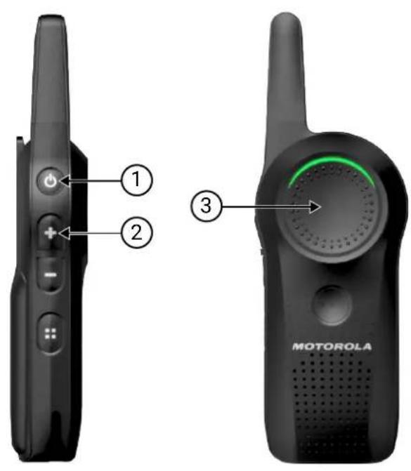
Number Description
1 PTT button
2 Volume Up button
3 Power button
11.2
Browsing Advanced Configuration Options
Procedure:
- Upon entering advanced configuration mode, you hear "Programming Mode. Press Menu button to continue" voice prompt from your radio.
- To browse through advanced configuration options, press Channel/Menu button.
- To exit advanced configuration mode, press and hold the PTT button.
Figure 6: Advanced Configuration Options
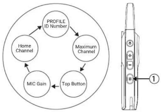
flowchart
graph TD
    A["PROFILE ID Number"] --> B["Home Channel"]
    A --> C["Maximum Channel"]
    B --> D["MIC Gain"]
    C --> D
    D --> E["Top Button"]
    E --> A
Number Description
1 Channel/Menu button
11.2.1
Entering Current PROFILE ID Number
Procedure:
- Press the Channel/Menu button until you hear "PROFILE ID number default is 0000" and voice prompt from your radio to change it.

NOTE: Change the Profile ID number to avoid interferences and improve privacy.
- To enter the Profile ID number sub-menu, press the Volume Up button or Volume Down button.
- To continue to the next advanced configuration option, press the Channel/Menu button.
Figure 7: Profile ID Number - Current Value
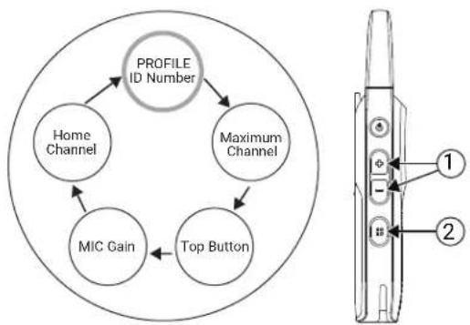
flowchart
graph TD
    A["PROFILE ID Number"] --> B["Home Channel"]
    A --> C["Maximum Channel"]
    A --> D["MIC Gain"]
    A --> E["Top Button"]
    F["Device Interface"] --> G["1"]
    F --> H["2"]
Number Description
1 Volume Up button or Volume Down button.
Press to enter the PROFILE ID Number sub-menu.
2 Channel/Menu button.
Number Description
Press to continue to the next Advanced Configuration option.
11.2.2
Changing PROFILE ID Number
Procedure:
-
To enter and change the PROFILE ID Number sub-menu, press the Volume Up button or Volume Down button.
You hear "There is 10,000 options of PROFILE ID Number to choose from (0000 - 9999)" voice prompt from your radio. -
To change the first digit, press the Volume Up button or Volume Down button.
-
To continue to the next digit, press Channel/Menu button.
Figure 8: Profile ID Number
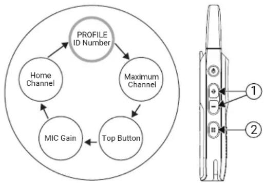
flowchart
graph TD
    A["PROFILE ID Number"] --> B["Home Channel"]
    A --> C["Maximum Channel"]
    B --> D["MIC Gain"]
    C --> D
    D --> E["Top Button"]
Number Description
| 1 Volume Up button or Volume Down button. | Press to change the first digit. |
| 2 Channel/Menu button. | Press to continue to the next digit. |
11.2.3
Changing PROFILE ID Number in Sub-Menu
Procedure:
- To change the current digit, press the Volume Up button or Volume Down button.
You hear the value voice prompt from your radio.
-
To continue to the next digit, press Channel/Menu.
-
When you have entered the fourth digit, press the Channel/Menu button again to continue to the next advanced configuration option.

NOTE: You have the option to browse forward through the four digits using the Channel/Menu button. However, you do not have the option to browse backward through the four digits of PROFILE ID Number.
Figure 9: Profile ID Number in Sub-Menu
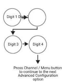
flowchart
graph TD
    A["Digit 1 Digit 3"] --> B["Digit 3"]
    B --> C["Digit 4"]
    C --> D["Press Channel / Menu button to continue to the next Advanced Configuration option"]
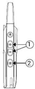
Number Description
| 1 Volume Up button or Volume Down button. | Press to change the first digit. |
| 2 Channel/Menu button. | Press to continue to next digit. Once in the last digit, press the button again to continue to the next advanced configuration option. |
11.2.4
Confirming Modified PROFILE ID Number
Procedure:
- Set the four digit PROFILE ID number.
You hear the new PROFILE ID number voice prompt from your radio.

NOTE: If the four digit PROFILE ID number announced is not the correct number, press the Channel/Menu button, and cycle through the advanced configuration options until you return to the PROFILE ID number option to change the value.
- To continue to the next advanced configuration option, press the Channel/Menu button.
Figure 10: Modified PROFILE ID Number Confirmation
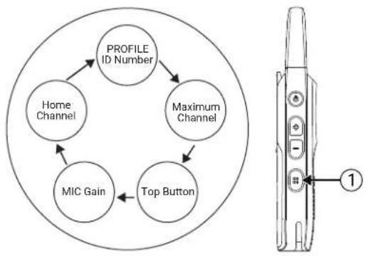
flowchart
graph TD
    A["PROFILE ID Number"] --> B["Home Channel"]
    A --> C["Maximum Channel"]
    B --> D["MIC Gain"]
    C --> D
    D --> E["Top Button"]
Number Description
1 Channel/Menu button.
Press to continue to the next advanced configuration option.
- To exit the advanced configuration mode, long press the PTT button.
11.2.5
Setting Maximum Channels
The maximum number of channels you can set up in your radio is according to your radio model. DRLx1100 radio has maximum 10 channels.
Procedure:
- Press the Channel/Menu button until your radio announces the current maximum number of channels and prompts you to change it.
- To change the number of channels, press the Volume Up button or Volume Down button.
- To continue to the next advanced configuration option, press the Channel/Menu button.
Figure 11: Maximum Channels Setup
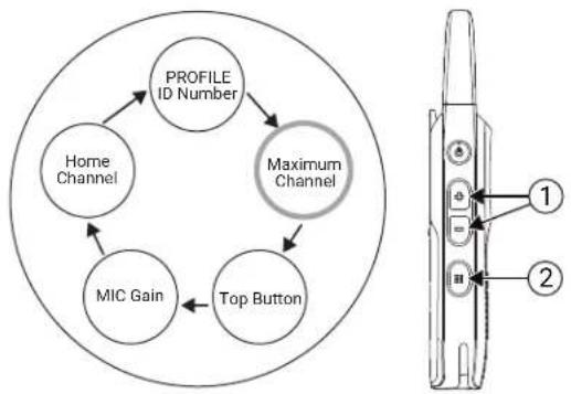
flowchart
graph TD
    A["PROFILE ID Number"] --> B["Home Channel"]
    B --> C["MIC Gain"]
    C --> D["Top Button"]
    D --> E["Maximum Channel"]
Number Description
1 Volume Up button or Volume Down button.
Press to change the number of channels.
Number Description
2 Channel/Menu button.
Press to continue to the next advanced configuration option.
11.2.6
Entering Top Button - Current Feature
Procedure:
- Press the Channel/Menu button until your radio announces the current Top button feature and prompts you to change it.
- To enter the Top button sub-menu, press the Volume Up button or Volume Down button.
- To continue to the next advanced configuration option, press the Channel/Menu button.
Figure 12: Top Button - Current Feature
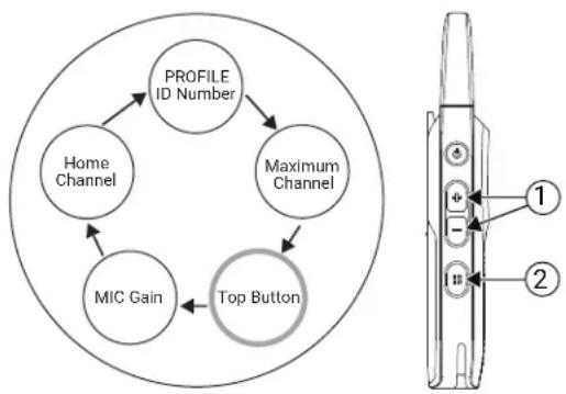
flowchart
graph TD
    A["PROFILE ID Number"] --> B["Home Channel"]
    A --> C["Maximum Channel"]
    B --> D["MIC Gain"]
    C --> E["Top Button"]
Number Description
1 Volume Up button or Volume Down button.
Press to enter the Top button sub-menu.
2 Channel/Menu button.
Press to continue to the next advanced configuration option.
11.2.6.1
Browsing Top Button - Sub-Menu Options
Procedure:
- To browse through the different options in Top button sub-menu, press the Volume Up button or Volume Down button.
You hear voice prompts from your radio as you navigate through the feature.
- To continue to the next advanced configuration option, press the Channel/Menu button.

NOTE: To use Direct Call option, you must enable the feature in Customer Programming Software (CPS). Otherwise Top button sounds an error tone even if you choose the option in the menu.
Figure 13: Top Button - Sub-Menu Options
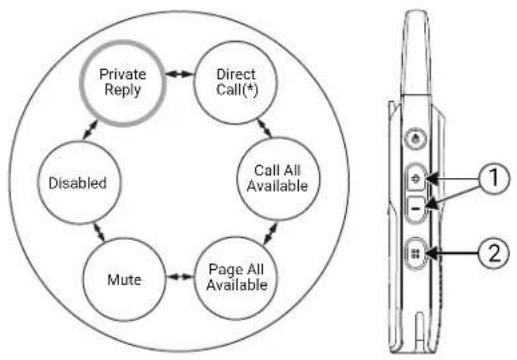
flowchart
graph TD
    A["Private Reply"] --> B["Direct Call(*)"]
    B --> C["Call All Available"]
    C --> D["Page All Available"]
    D --> E["Mute"]
    E --> F["Disabled"]
    F --> A
| Number Description | |
| 1 Volume Up button or Volume Down button. | Press to browse through the Top button option in sub-menu. |
| 2 Channel/Menu button. | Press to continue to the next advanced configuration option. |
11.2.7
Setting MIC Gain
You can change your Microphone (MIC) Gain setting to low, medium, or high. The default setting for MIC Gain is medium.
Procedure:
- Press the Channel/Menu button until your radio announces the MIC Gain setting and prompts you to change it.
- To change the MIC Gain setting, press the Volume Up button or Volume Down button.
- To continue to the next advanced configuration option, press the Channel/Menu button.

NOTE: You should only change the MIC Gain setting if other users complain that the volume from your radio is too low or too high. The default medium setting is appropriate for most users, so it can be left unchanged.
Figure 14: MIC Gain Setup
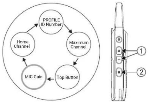
flowchart
graph TD
    A["PROFILE ID Number"] --> B["Home Channel"]
    A --> C["Maximum Channel"]
    B --> D["MIC Gain"]
    C --> D
    D --> E["Top Button"]
| Number Description | |
| 1 Volume Up button or Volume Down button. | Press to change MIC Gain settings. |
| 2 Channel/Menu button. | Press to continue to the next advanced configuration option. |
11.2.8
Setting Home Channel
You can change your home channel setting to Disabled or Channel number (or channel name if alias was set up in CPS). The default setting for home channel is Disabled.
Procedure:
- Press the Channel/Menu button until your radio announces the home channel setting and prompts you to change it.
- To change the home channel setting, press the Volume Up button or Volume Down button.
- To go back to the first advanced configuration option – PROFILE ID Number, press the Channel/Menu button.

NOTE: When home channel is enabled and there is no activity detected from a channel for seven seconds, the radio reverts to home channel. This feature may not be appropriate if you need to frequently change channels throughout the day.
Figure 15: Home Channel Setup
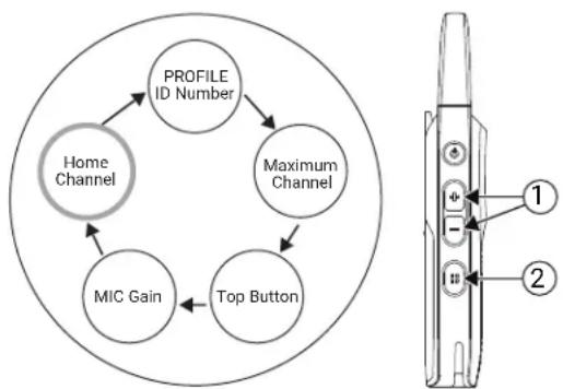
flowchart
graph TD
    A["Profile ID Number"] --> B["Home Channel"]
    B --> C["MIC Gain"]
    C --> D["Top Button"]
    D --> E["Maximum Channel"]
    E --> A
| Number Description | |
| 1 Volume Up button or Volume Down button. | Press to change home channel settings. |
| 2 Channel/Menu button. | Press to go back to the first advanced configuration option. |
11.2.9
Resetting to Factory Defaults
Procedure:
To reset your radio to the original factory defaults, press PTT → Volume Up → Volume Down → Power buttons at the same time.
You hear resetting beeps and "Battery Level
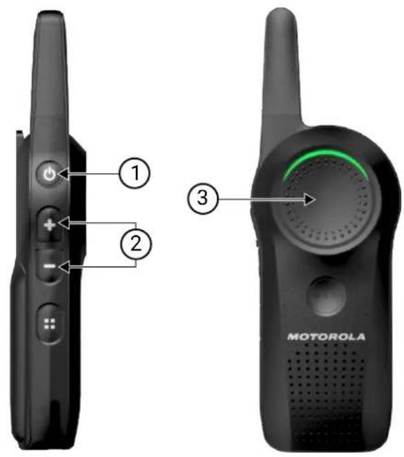
| Number Description |
| 1 PTT button |
| 2 Volume Up button and Volume Down button |
| 3 Power button |
11.2.9.1
Radio Factory Default Settings
Table 22: Radio Basic Feature Defaults
| Radio Basic Feature Default |
| Power up announcement Battery Status and Channel Name |
| Quick press Power button Battery Status |
Radio Basic Feature Default
Number of channels Set to maximum number of channels supported by the radio model
Channel/Menu button Channel change only
Top button feature Private Reply
Table 23: Radio Advanced Configuration Mode Defaults
| Radio Basic Feature Default |
| PROFILE ID Number lock Off |
| Radio PROFILE ID Number 0000 |
| Maximum Channels Set to maximum number of channels supported by the radio model |
| Direct Call Off |
| MIC Gain Medium |
| Home Channel Disabled |
| Battery Save On |
| Power Save Off |
| Programmable button Call All Available |
Table 24: Radio Special Mode Defaults
| Radio Special Mode Default |
| Enable restore Factory Default reset On |
| Enable Advanced Configuration Mode On |
| Enable Cloning Mode On |

NOTE: For other radio default setting, refer to Customer Programming Software (CPS).
Chapter 12
Customer Programming Software
You can program or change features in your radio by using Customer Programming Software (CPS) and the CPS programming cable (Part Number HKKN4027_).
CPS gives you the flexibility to prevent radio features to be accidentally modified by users by providing the option to disable functionalities like Factory Reset, and Advanced Configuration Mode. It provides security by giving the option to set up a password for profile radio management.
For United States, Canada, Australia, and New Zealand, you can download the software for free at http://www.motorolasolutions.com/curve. For Latin America, contact Motorola Solutions Authorized Distributor for CPS information.
12.1
Setting Radio to Customer Programming Software
Prerequisites: Verify that the switch in the Programming Cable is in Digital position. If your Customer Programming Software (CPS) Programming Cable is showing "CPS/Flash," ensure to position it to "Flash".
Procedure:
To program, connect the radio from the Drop-in Charger Tray and CPS Programming Cable to your computer.
Figure 16: Setting-Up the Radio to the CPS
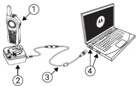
Table 25: Setting-Up the Radio to the CPS
| Number Description |
| 1 Radio |
| 2 Single Unit Charger (SUC) |
| 3 CPS Programming Cable |
| 4 Computer Cable Port |
12.2
Customer Programming Software Basic Menu Instructions
Procedure:
- Open the Customer Programming Software.
- Click on the RADIO top tab.
- Perform one of the following actions:
a. Click on the READ tab to read the radio. ^11
b. If you want to open a new profile or an existing one, from the drop-down menu Radio Type, select Curve.
To open an existing profile with password protection, enter your CPS profile password. ^12
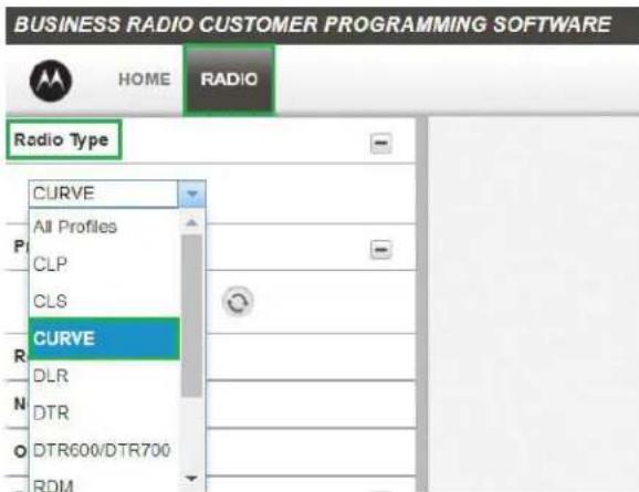
- Perform one of the following actions:
a. Click Read Radio.
The radio sounds a series of tones to indicate that reading is in progress and uploads your radio profile settings.
b. To create customized profile based on the default profile, click New Profile.
MN007944A01-AH
Chapter 12: Customer Programming Software
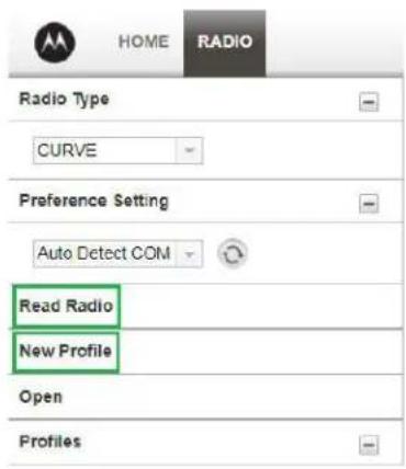
- Scroll down to see more feature options. Customize as necessary.
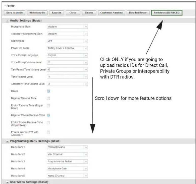
- Choose which options you want available in the advanced configuration mode. Add any of the features shown to be accessed by the radio Channel/Menu button in the radio basic operation mode.
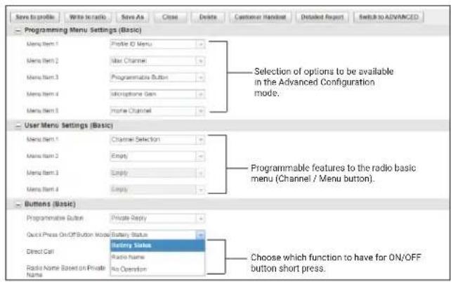

NOTE: You can also choose the function of the Power button press.
- Modify the radio Top button feature by changing the default option.
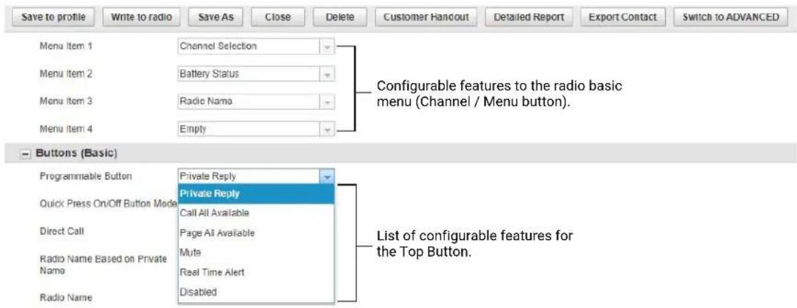
- To enable the Direct Call feature in your basic menu options, perform the following actions:
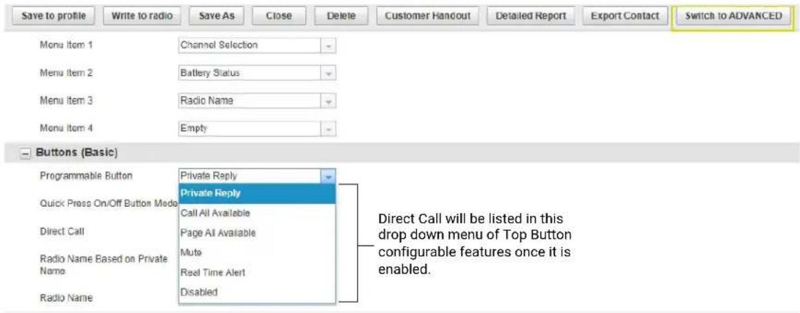
a. Upload one or more radios unique private identification (12 digit) number.
b. Click on the Switch to ADVANCED button.
c. On Privates (Advanced) tab, click the Add button for CPS to upload the radio ID.
d. Customize the radio ID name under the Name column. After a radio ID is uploaded, the CPS enables the Direct Call feature.
- You can export all available public group contacts to an xml file to be used in the portal by using the Export Contact button.
a. Click on the Switch to ADVANCED button.
b. On Public Groups (Advanced) tab, click the Add button for CPS to upload the group ID.

NOTE: Direct call groups are limited to Public Group 21 to Public Group 100.
c. Customize the group name under the Name column.
d. Click on the Export Contact button.
e. Save the group contacts in an xml file.
f. Import the group contacts to Curve Portal. See the Curve Portal User Guide for more information on importing new groups.
- Set a PROFILE ID number for any four-digit number different from "0000" to differentiate your radios in a radio fleet.
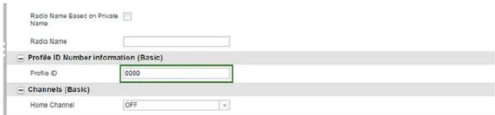
- Assign the Home Channel by performing the following actions:
a. To assign a specific channel as your Home Channel, select the channel using the drop-down menu under Home Channel. CPS enables the option to choose any channel you want as your designated Home Channel for the radio that you are programming.
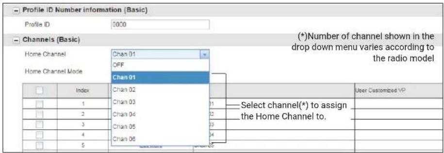

NOTE: The Home Channel is turned off by default.
b. After setting your Home Channel, select the mode using the drop-down menu under Home Channel Mode.
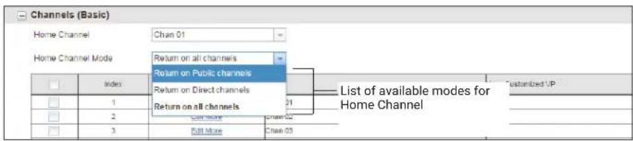
- Customize the name of your channel (alias) in the Name column.
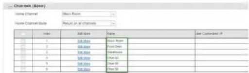
- Configure a customized Channels Voice Prompt by performing the following steps:
a. Click Edit More to edit the voice prompt.
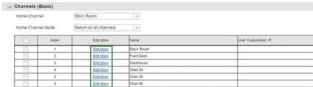
You can set your own customized Channels Voice Prompt (VP) to enable your channel name to be announced by the radio.
b. Select the Enable User Customized VP check box to enable the standard Voice Prompt.
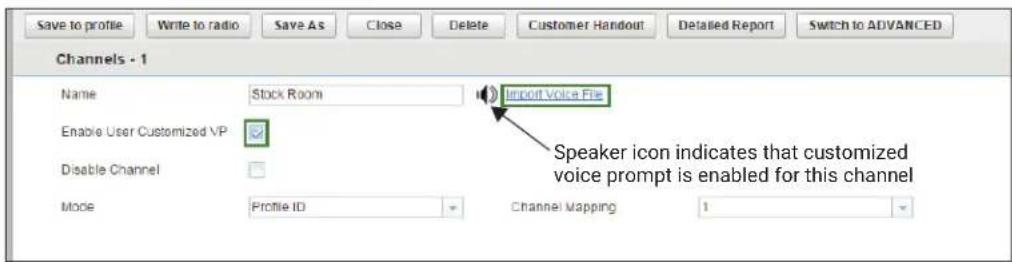
When a speaker icon appears in the menu, then that channel has a customized voice prompt enabled.
c. Click the speaker icon to preview the User Customized VP.
d. If you want to include your own voice recording, click on Import Voice File ^13 .
- Modify the configurable fields for your Wi-Fi and intelligent insight feature in the Cloud Settings (Basic) section.
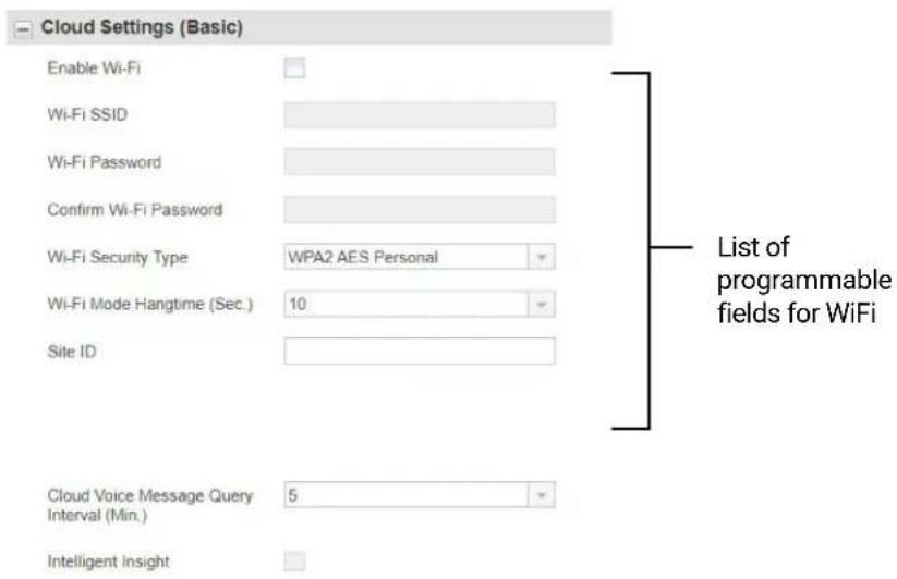

NOTE:
- You must extract the Site ID from the Curve Portal.
-
You must enable the Enable Wi-Fi checkbox to use the intelligent insight feature.
-
Modify the radio Programmable button feature by changing the default option.
- After changing all the settings, program your radio by clicking Write to radio button.
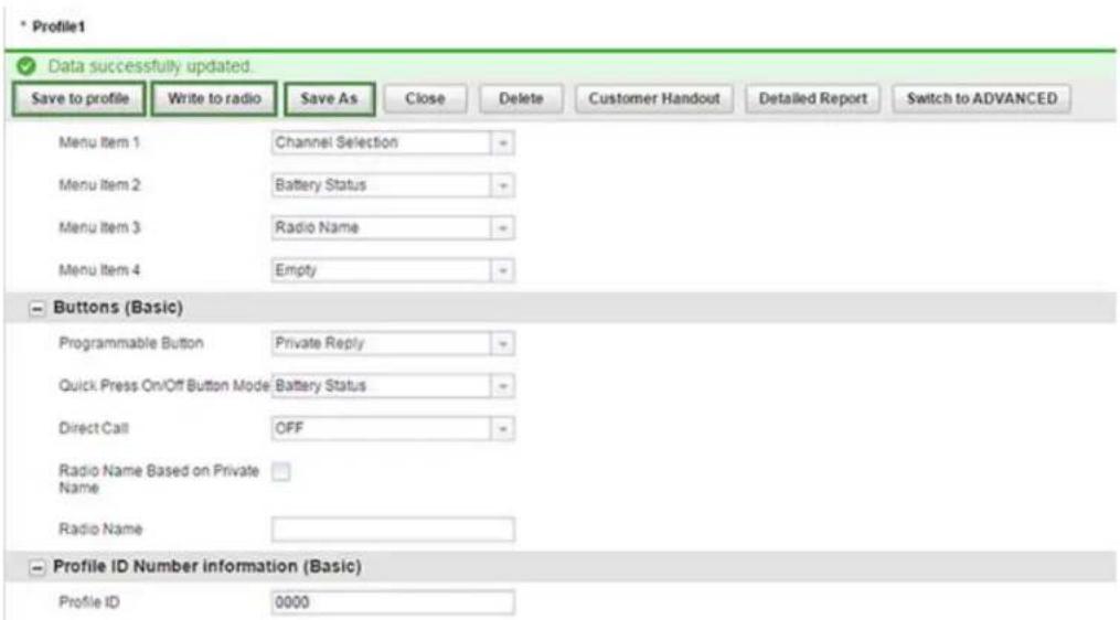
CPS displays a window confirming the programming of your radio is successful.

NOTE: Save your profile at any time to use the same settings when programming other radios by clicking on Save to profile button. This saves the profile to the current default path on your computer. To specify a different path to save the profile, click the Save As button.
Chapter 13
Cloning Mode
You can clone radio profiles from a Source radio to a Target radio.
Use the following devices/tools to perform cloning mode:
- Multi-Unit Charger (MUC) – Optional accessory
- Two Single Unit Chargers (SUC) and a Radio-to-Radio cloning cable - Optional accessory
- Customer Software Programming (CPS) – Free software download
- Wireless PIN cloning
Contact your dealer for more information.
13.1
Configuring Serial/Profile ID Cloning Mode
Procedure:
Press PTT → Volume Down → Power buttons at the same time.
You hear Cloning Mode beeps and "Cloning Mode, Serial" voice prompt from your radio.
Figure 17: Serial/Profile ID Cloning Mode Sequence
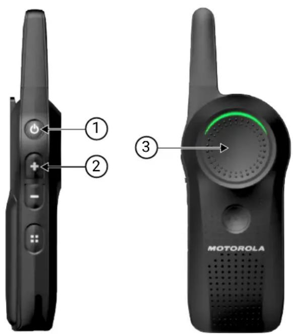
Table 26: Serial/Profile ID Cloning Mode
| Number Description |
| 1 PTT button |
| 2 Volume Down button |
| 3 Power button |
13.2
Configuring OTA Wi-Fi Cloning Mode
Procedure:
Press Volume Down → VAB → Power buttons at the same time.
You hear "Wi-Fi Cloning" voice prompt from your radio. The front LED flashes red and green.
Figure 18: Over-the-Air (OTA) Wi-Fi Cloning Mode Sequence
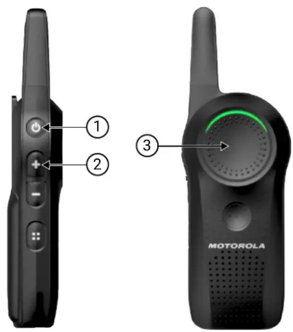
Table 27: OTA Wi-Fi Cloning Mode
| Number Description |
| 1 Volume Down button |
| 2 VAB button |
| 3 Power button |
13.3
Clone Mode in Multi-Unit Charger
You can clone radio profiles in a Multi-Unit Charger (MUC).
When in cloning mode, you must have at least two radios.
● A fully-charged battery in each of the radios.
- A source radio where the profiles are copied or cloned to a target radio.
- A target radio where the profiles are cloned from the source radio.
The placement for source radio in MUC is in pocket 1 and 2. The placement for target radio in MUC is in pocket 4 and 5.
Match the placement for source and target radios in MUC as follows:
- 1 and 2
• 4 and 5

NOTE: Read MUC pocket numbers from left to right with the Motorola Solutions logo facing front.
When pairing the source and target radio, use the same band type for successful cloning mode.
When cloning, the MUC does not need to be connected to a power source.
Figure 19: Cloning Mode in Multi-Unit Charger
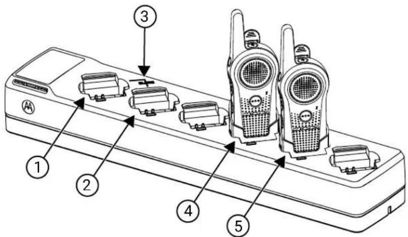
Table 28: Cloning Mode in Multi-Unit Charger
| Number Item |
| 1 Pocket 1 |
| 2 Pocket 2 |
| 3 "CLONE" symbol |
| 4 Pocket 4 |
| 5 Pocket 5 |
13.3.1
Configuring Cloning Mode in Multi-Unit Charger
Prerequisites: Ensure all radios are fully charged.
Procedure:
- Turn on the target radio.
- Place the target radio into the Multi-Unit Charger (MUC) target pocket. See Clone Mode in Multi-Unit Charger on page 89 for the correct placement.
- To turn on the source radio, press PTT and Volume Down buttons simultaneously for three seconds. You hear Cloning Mode beeps, and your radio announces "Cloning Mode, Serial".
- Place the source radio into the paired MUC target pocket. See Clone Mode in Multi-Unit Charger on page 89 for the correct placement.
- Press the + button.
Your radio announces "Fail" or "Pass". - To exit Cloning Mode, press and hold the PTT button.
13.4
Configuring Cloning Mode Using Radio to Radio Cloning Cable
Prerequisites:
Ensure all radios are fully charged.
Required devices/tools:
- Cloning Cable (Part Number HKKN4028_)
- Two Single-Unit Chargers (SUC)
When and where to use:
Figure 20: Radio to Radio Cloning
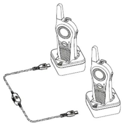
natural_image
Line drawing of two walkie-talkie holders connected to a power cord (no text or symbols)Procedure:
-
Turn the radio off.
-
Unplug any cables from the SUC.
- Plug one side of the cloning cable mini USB connector to the first SUC, and the other end to the second SUC.

NOTE: During the cloning process, no power is being applied to the SUC. The batteries are not charged. Only data communication is being established between the two radios.
- Turn on the Target Radio and place it into one of the SUCs.
- To turn on the Source Radio, press PTT and Volume Down buttons simultaneously for three seconds.
You hear Cloning Mode beeps, and "Cloning Mode, Serial" voice prompt from your radio.
- For the Source Radio, power on the radio with the following sequence:
a. Press the PTT and Volume Up buttons at the same time while turning the radio on. Wait three seconds before releasing the buttons, and you hear "Clone Mode Serial" voice prompt from your radio.
b. Place the Source Radio in its SUC. Press and release the Volume Up button.
You hear "Pass" or "Fail" voice prompt from your Source radio.
- To exit the clone mode when the process is completed, press the Power button, or long press the PTT button.
13.5
Cloning Mode Status Indicator
Press and hold both the PTT button and Volume Down button at the same time, while turning on the radio to enter cloning mode.
Table 29: Cloning Mode Status Indicator
| Cloning Mode Status LED Indicator Voice Prompt or Tone | |
| Cloning Mode (by default is Serial) | Double Blink Red “Clone Mode, Serial” |
| Switch to Wireless Cloning [initiated by (-) button] | Double Blink Red “Wireless” |
| Switch to Serial Cloning [initiated by (-) button] | Double Blink Red “Serial” |
| Clone [initiated by (+) button] – Cloning in progress | Solid Red Cloning beeps |
| Cloning Successful Not Available “Pass” | |
| Cloning Fail Not Available “Fail” | |
13.6
Troubleshooting Cloning Mode
When and where to use:
The radio audible voice announces "Fail" indicating that the cloning process has failed. In the event that cloning fails, perform each of the following steps before attempting to start cloning process again.
Procedure:
- Ensure that the batteries on both radios are fully charged and engaged properly on the radio.
- Check the cloning cable connection on both Single-Unit Chargers (SUC) and if the cable is switched to "Cloning".
- Ensure that there is no debris in the charging tray or on the radio contacts and the radio contact is touching the SUC or Multi-Unit Charger (MUC) contact firmly.
- Ensure that the target radio is turned on.
- Ensure that the source radio is in cloning mode.
6.

NOTE: The cloning cable is designed to operate only with compatible Motorola Solutions SUC.
Result: When ordering cloning cable kit, ensure to order the cloning cable kit with part number HKKN4028_. For more information about the accessories, see Accessories on page 101.
13.7
Cloning Mode Using Wireless PROFILE ID Number
The PROFILE ID Number Wireless Cloning feature is useful when you want to clone the PROFILE ID number for all the radios in your fleet, but you do not want to clone particular radio settings that may be unique for each radio such as Top button configuration, MIC Gain, Radio Name and others. Wireless PROFILE ID preserves each user radio setup, but ensure that all radios are under the same PROFILE ID number. This feature is useful if you do not have a programming Cable, Cloning Cable, or PC easily available.
13.7.1
Configuring Cloning Mode Using Wireless PROFILE ID Number

NOTE: Serial cloning for Curve series is compatible with DLR radios only.
Procedure:
- Turn the Source Radio on by performing the following actions:
a. Press the PTT and Volume Down buttons at the same time while turning the radio on.
b. Wait three seconds before releasing the buttons until you hear "Clone Mode Serial" voice prompt from the Source radio.
a. Press and release the Volume Down button.
You hear "Wireless" from the Source radio.
- Turn on the Target radio by performing the following actions:
a. Press the PTT and Volume Down buttons at the same time while turning the radio on.
b. Wait three seconds before releasing the buttons until you hear "Clone Mode Serial" voice prompt from the Target radio.

NOTE: Avoid putting powered on radios (more than seven radios) in a container together, other than the Multi-Unit Charger.
-
To start the wireless PROFILE ID Number cloning on the Source Radio, press and release the Volume Up button.
-
You hear a tone.
- After cloning is completed, you hear "Pass" indicating cloning is successful or "Fail" indicating cloning failed voice prompt from the Source radio.
- On the Target radio, the radio receives the PROFILE ID Number information. You hear "Pass" indicating cloning is successful or "Fail" indicating cloning failed voice prompt from the Target radio.
13.8
OTA Wi-Fi Cloning
The Over-the-Air (OTA) Wi-Fi Cloning feature allows you to clone selected types of data through Wi-Fi to all the radios in your fleet without the use of any programming cable, cloning cable, or PC. You can find the OTA Wi-Fi Cloning feature in the Customer Programming Software (CPS), under the Cloud Settings (Basic) configuration.
You can clone the following types of data through OTA Wi-Fi:
- Enable Wi-Fi.
- Wi-Fi SSID
- Wi-Fi Password
- Wi-Fi Security type
- Wi-Fi Mode hangtime
- Site ID
- Cloud Voice Message Query Interval
- Intelligent Insight
- Profile ID
The duration for each cloning process takes approximately three minutes.
13.8.1
Entering OTA Wi-Fi Cloning Mode
Prerequisites:
- Ensure that the distance between Target and Source radios is at least 1 meter apart.
● While cloning, do not press the Power Down button or remove the battery. - Profile ID Number Lock is checked for all Target radio.
Procedure:
- Turn on the Source and Target radios.
-
Press Volume Down → VAB → Power buttons at the same time to enter Wi-Fi provisioning mode. This button sequence to enter Wi-Fi provisioning mode applies to the Source and Target radios.
You hear the "Wi-Fi Cloning" voice prompt from your radio. The front LED flashes red and green. -
Press the Volume Up button on the Source radio to trigger the OTA Wi-Fi cloning process.
Good key chirps are played from the Source radio after each data is transmitted to the Target radio. On the Source radio, you can observe static and the top LED displays solid orange LED. For the Target radio, the top LED flashes orange.

NOTE: The cloning process uses Hopset 10. Any radio configurations that use Hopset 10 are likely to experience interference during the data transfer process and during voice communication.
Result:
If cloning is successful:
You can hear the “Cloning Successful” voice prompt from both radios, and the target radio automatically restarts.
If cloning fails:
You can hear the "Cloning Failed" voice prompt from the source radio, and a bad bonk is played. Restart the cloning process by pressing the Volume Up button on the Source radio.

NOTE: The following lists the possible scenarios that cloning fails.
- If one of the Target radios is interrupted during the cloning process. However, the cloning process for other Target radios still continues.
- If you started a late entry Target radio during a cloning process.
- If the Source radio interrupts the ongoing cloning process.
Chapter 14
Troubleshooting
Troubleshoot your radio using the method described in the table.
Table 30: Troubleshooting
| If... Then... | |
| If there is no power, recharge or replace the Li-ion battery. | |
| NOTE: Extreme operating temperature may affect battery life.See Battery Specifications on page 16. | |
| If Customer Programming Software (CPS) is unable to read the radio, | perform one of the following actions:Ensure that one side of the programming cable is connected to the radio,and the other side of the programming cable is connected to the USB port.Verify that the switch on the programming cable is set at Digital position or Flash position in older version programming cable.Ensure that the radio is positioned correctly inside the Single-Unit Charger (SUC). |
| If the radio generates continuous tone when pressing the PTT button, | press the PTT button again when receive mode ends. |
| If the radio does not transmit audio when pressing the PTT button, | perform one of the following actions:Verify that nobody else is using the channel and try again.When using an earpiece, ensure that the PTT button is disabled.Ensure to use the earpiece in-line with PTT button to transmit. |
| If you receive communication that is not within your channel, | customize your PROFILE ID to a 4-digit number for all radios. |
| If you hear a cracking noise when nobody is talking, | perform one of the following actions:While wearing the radio on belts or pockets, check if the PTT button is not against another object.Use earpiece. |
| If the audio quality is not good, perform the following actions: | |
| Check if the radio settings are the same in all radios.Go to Advanced Configuration Mode.Adjust the microphone sensitivity gain (MIC Gain). | |
If... Then...
| If the audio sounds garbled/robotic, | ensure that you are within transmission range. |
| NOTE: Digital technology gives you the advantage to experience clear audio up to the edge of the range. However, when maximum transmission range has been reached, audio may sound garbled just before the transmission is lost completely. | |
| If the transmitted audio is low, hold the radio vertically 1 inch to 2 inches from your mouth when talking.For accessory, hold the accessory microphone 2 inches to 3 inches from your mouth when talking. | |
| If there is a loud tone interrupting the conversation, | perform the following actions:When talking, ensure not to release the PTT button at any moment.Always press the PTT button firmly, until transmission completes.Ensure not to release the PTT button while transmitting, and not to immediately press the PTT button again.Ensure the channel is available, and there is a user reachable within the transmission range. |
| If there is a limited talk range, perform the following actions:Check for clear line of sight to improve transmission. Avoid being near steel and/or concrete structures, heavy foliage, buildings, or vehicles.Change the placement of the radio. Ensure your radio is not too close to your body, such as in a pocket or on a belt. | |
| NOTE: Radios provide greater coverage in industrial and commercial buildings. | |
| If the radio echo feedback, perform one of the following actions:Lower the volume in your radio, and ensure that transmitting and receiving radios are not too close.Use earpiece. | |
| If your voice is not transmitted or received, | perform the following actions:Ensure that the PTT button is completely pressed when transmitting.Ensure that the radios have the same settings, and the same PROFILE ID.Before talking, wait until you hear the Talk Permit Tone. Speaking before hearing the tone results in the first few words of the transmission being cut out.Recharge, replace, or reposition the batteries. See Battery Specifications on page 16.Change to a location with no interference. |
If... Then...
| If you hear heavy static or interference, | ensure that transmitting and receiving radios are at least five feet apart. |
| If the Drop-in Charger LED light does not blink, | perform the following actions:1. Verify that the radio/battery is properly inserted.2. Check the battery/charger contacts to ensure that they are clean and charging pin is inserted correctly.Refer to Charging with the Drop-In Tray Single-Unit Charger (SUC) on page 18, Radio Status on page 31 and Attaching the Battery on page 26. |
If the battery is low, recharge or replace the battery.

NOTE: Extreme operating temperature may affect battery life. See Battery Specifications on page 16.
| If low battery indicator is blinking although new batteries are inserted, | refer to Attaching the Battery on page 26 and Battery Specifications on page 16. |
| If the battery does not charge although it has been placed in the drop-in charger for a while, | perform the following actions:Verify that the drop-in tray charger is properly connected and corresponds with a compatible power supply. See Charging with the Drop-In Tray Single-Unit Charger (SUC) on page 18 and Charging a Stand-Alone Battery on page 18.Check the charger LEDs indicators to see if the battery is in error state. |
Chapter 15
Motorola Solutions Limited Warranty
For Australia and New Zealand, refer to the warranty card included in your package.
15.1
Warranty
Subject to the exclusions contained below, Motorola Solutions, Inc. warrants its two way radios to be free from defects in materials and workmanship under normal consumer usage for the period(s) outlined.
This limited warranty is a consumer's exclusive remedy, and applies as follows to new Motorola Solutions Products, Accessories and Software purchased by consumers in the United States, which are accompanied by this written warranty.
15.2
Products and Accessories
The table shows the length of coverage of products and accessories.
Table 31: Products and Accessories
| Products Covered Length of Coverage | |
| Business two-way radio accessories One (1) year from the date of purchase by the first purchaser of the product. | |
| Products and accessories that are repaired or replaced | The balance of the original warranty or for 90 days from the date returned to the consumer, whichever is longer. |
| Two-way radio Two (2) years from the date of purchase by the first purchaser of the product. Two (2) years from the date of purchase by the first purchaser of the product. | |
15.3
Exclusions
Normal Wear and Tear
Periodic maintenance, repair, and replacement of parts due to normal wear and tear are excluded from coverage.
Batteries
Only batteries whose fully charged capacity falls below 80% of their rated capacity and batteries that leak are covered by this limited warranty.
Abuse and Misuse
Defects or damage that result from:
- Improper operation, storage, misuse or abuse, accident or neglect, such as physical damage (cracks, scratches, and more.) to the surface of the product resulting from misuse.
- Contact with liquid, water, rain, extreme humidity or heavy perspiration, sand, dirt, or the like, extreme heat, or food.
- Use of the Products or Accessories for commercial purposes or subjecting the Product or Accessory to abnormal usage or conditions.
- Other acts that are not the fault of Motorola Solutions, are excluded from coverage.
Use of Non-Motorola Solutions Products and Accessories
Defects or damage that result from the use of Non-Motorola Solutions branded or certified Products, Accessories, Software, or other peripheral equipment are excluded from coverage.
Unauthorized Service or Modification
Defects or damages resulting from service, testing, adjustment, installation, maintenance, alteration, or modification in any way by someone other than Motorola Solutions, or its authorized service centers, are excluded from coverage.
Altered Products
Products or Accessories with:
- Serial numbers or date tags that have been removed, altered, or obliterated.
● Broken seals or that show evidence of tampering. - Mismatched board serial numbers.
● Nonconforming or non-Motorola Solutions housings, or parts, are excluded from coverage.
Communication Services
Defects, damages, or the failure of Products, Accessories, or Software due to any communication service or signal you may subscribe to or use with the Products Accessories or Software is excluded from coverage.
15.4
Software
Table 32: Software Warranty Table
| Products Covered Length of Coverage | |
| SoftwareApplies only to physical defects of the media that embodies the copy of the software. | 90 days from the date of purchase. |
| Converter ToolsApplies to Latin America only.When the radio is converted, the conversion is not reversible. | The 2-way radio is covered exclusively warranty of Two (2) years from the date of purchase by the first purchaser of the product.In the case of tool failure, the radio is bound to the warranty provided that all the precautions have been handled correctly. |
Exclusions
Software Embodied in Physical Media
The warranty does not cover that the software will meet your requirements or will work in combination with any hardware or software applications provided by third parties, that the operation of the software products will be uninterrupted or error free, or that all defects in the software products will be corrected.
MN007944A01-AH
Chapter 15: Motorola Solutions Limited Warranty
Software not Embodied in Physical Media
Software that is not embodied in physical media (for example, software downloaded from the internet), is provided "as is" and without warranty.
15.5
Warranty Coverage
This warranty extends only to the first consumer purchaser, and is not transferable.
15.6
How to Obtain Warranty Service or Other Information
- United States and Canada: contact your Motorola Solutions point of purchase.
- Latin America: contact customercare.service@motorolasolutions.com.
● Australia and New Zealand: refer to the warranty card included in your package.
15.7
Patent Notice
This product is covered by one or more of the following United States patents.
5896277 5894292 5864752 5699006 5742484 D408396 D399821 D387758 D389158 5894592 5893027 5789098 5734975 5861850 D395882 D383745 D389827 D389139 5929825 5926514 5953640 6071640 D413022 D416252 D416893 D433001
15.8
Export Law Assurances
This product is controlled under the export regulations of the United States of America. The Government of the United States of America may restrict the exportation or re-exportation of this product to certain destinations.
For further information, contact the U.S. Department of Commerce.
For questions or comments related to this product, please contact Motorola Solutions 1-888-325-9336 or visit: http://www.motorolasolutions.com/curve
Appendix A
Accessories
Choose from a variety of accessories designed, tested, and certified to optimize the performance of this radio.
Table 33: Audio Accessories
| Part Number Description |
| PMLN8311_ Over-the-ear Earpiece with Eartip, 2.5 mm, Single Pin, Angled |
| PMLN8191_ Earpiece with Clear Tube, 2.5 mm, Single Pin, Angled |
Table 34: Battery
| Part Number Description |
| HKNN4013_Li-Ion Battery 1800 mAh |
| PMNN4578_Li-Ion Battery 2500 mAh |
Table 35: Battery Doors
| Part Number Description |
| PMLN8393_ Standard cap for BT90 |
| HN001884A01 High cap for BT110 |
Table 36: Cables
| Part Number Description |
| HKKN4027_ Business Radio Customer Programming Software (CPS) Cable Kit |
| HKKN4028_ Business Radio Cloning Cable Kit |
Table 37: Chargers
| Part Number Description |
| PMPN4587_Curve Single-Unit Charger (SUC) Kit (US Type) |
| PMPN4589_Curve 6-Pocket Multi-Unit Charger (MUC) (US Type) |
| PMPN4648_Curve Single-Unit Charger (SUC) Australia and New Zealand Kit |
| PMPN4651_Curve 6-Pocket Multi-Unit Charger (MUC) Australia and New Zealand Kit |
Table 38: Carry Accessories
| Part Number Description |
| PMLN8392_Curve Holster Kit |
Table des matières
9.2 Appel direct....40
MOTOROLA, MOTO, MOTOROLA SOLUTIONS, and the Stylized M Logo are trademarks or registered trademarks of Motorola Trademark Holdings, LLC and are used under license. All other trademarks are the property of their respective owners.
Droits de licence
© 2024 Motorola Solutions, Inc. All Rights Reserved
Chapitre 1
Introduction
natural_image
Illustration of a row of five identical walkieh machines (no text or symbols visible)natural_image
Line drawing of a walkie-talkie with a device inside a box, showing a downward arrow (no text or symbols)natural_image
Line drawing of a walkie-talkie on an electronic device tray with multiple ports (no text or symbols)Résultat :

REMARQUE :
12 VAB (touche Assistant vocal)
Prend en charge l'application Assistant vocal.

REMARQUE :
natural_image
Three-step diagram showing a mobile phone device being processed, with no visible text or symbols.natural_image
Technical line drawing of a mechanical component or bracket (no text or symbols)Procédure :
natural_image
Six identical walkieh machines arranged in two rows, labeled A and B, with no visible text or symbols on the devices themselves.9.1.1
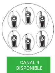
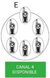
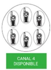
natural_image
Line drawing of a person holding a walkie-talkie with sound waves (no text or symbols)natural_image
Line drawing of a person holding a stethoscope (no text or symbols)10.1.5
bar
Menu Task Reminder | Time | Total Counts | |---|---| | 11:00 AM | 0 | | 12:00 PM | 0 | | 1:00 PM | 0 | | 2:00 PM | 2.0 | | 3:00 PM | 0 | | 4:00 PM | 0 | | 5:00 PM | 0 | | 6:00 PM | 0 | | 7:00 PM | 0 | | 8:00 PM | 0 | | 9:00 PM | 0 | | 10:00 PM | 0 | | 11:00 PM | 0 | | 11/4/2024 12:00 AM | 0 | | 1:00 AM | 0 | | 2:00 AM | 0 | | 3:00 AM | 0 | | 4:00 AM | 0 | | 5:00 AM | 0 | | 6:00 AM | 0 | | 7:00 AM | 0 | | 8:00 AM | 0 | | 9:00 AM | 0 | | 10:00 AM | 0 |10.6.4
natural_image
Line drawing of two walkie-talkie devices connected by a cable (no text or symbols)Procédure :
MOTOROLA, MOTO, MOTOROLA SOLUTIONS, and the Stylized M Logo are trademarks or registered trademarks of Motorola Trademark Holdings, LLC and are used under license. All other trademarks are the property of their respective owners.
© 2024 Motorola Solutions, Inc. All Rights Reserved
Capítulo 1
Introducción
Plantation, Florida 33322
natural_image
Illustration of a row of five identical walkieh machines (no text or symbols visible)natural_image
Illustration of a walkie-talkie with a device inside and a box below showing internal components (no text or symbols)natural_image
Line drawing of a walkie-talkie attached to a multi-pin electronic device (no text or symbols visible)Resultado:

NOTA:
natural_image
Three-step diagram showing a device being processed, with arrows indicating the process (no text or symbols present)natural_image
Technical line drawing of a mechanical component or bracket (no text or symbols)Procedimiento:
natural_image
Six identical walkieh machines arranged in two rows, labeled A and B, with no visible text or symbols on the devices themselves.9.1.1
flowchart
graph TD
    A["Canal 2 OCUPADO"] --> B["User with Habiando"]
    C["Escuchando"] --> D["User with Habiando"]
    E["Canal 3 DISPONIBLE"] --> F["User with Habiando"]
    G["Canal 4 DISPONIBLE"] --> H["User with Habiando"]
    I["User with Habiando"] --> J["User with Habiando"]
    K["User with Habiando"] --> L["User with Habiando"]
    M["User with Habiando"] --> N["User with Habiando"]
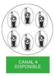
natural_image
Illustration of a person holding a walkie-talkie with sound waves (no text or symbols)natural_image
Line drawing of a person wearing a headset and holding a sphygmomanometer (no text or symbols)10.1.5
bar
Menu Task Reminder | Time | Total Counts | |---|---| | 11:00 AM | 0 | | 12:00 PM | 0 | | 1:00 PM | 0 | | 2:00 PM | 2.0 | | 3:00 PM | 0 | | 4:00 PM | 0 | | 5:00 PM | 0 | | 6:00 PM | 0 | | 7:00 PM | 0 | | 8:00 PM | 0 | | 9:00 PM | 0 | | 10:00 PM | 0 | | 11:00 PM | 0 | | 11/4/2024 12:00 AM | 0 | | 1:00 AM | 0 | | 2:00 AM | 0 | | 3:00 AM | 0 | | 4:00 AM | 0 | | 5:00 AM | 0 | | 6:00 AM | 0 | | 7:00 AM | 0 | | 8:00 AM | 0 | | 9:00 AM | 0 | | 10:00 AM | 0 |10.6.4
natural_image
Line drawing of two walkie-talkie devices connected by a cable (no text or symbols)Procedimiento:
Nome: Motorola Solutions, Inc.
Endereço: 2000 Progress Pkwy, Schaumburg, IL. 60196
Telephone: 1-800-927-2744
MOTOROLA, MOTO, MOTOROLA SOLUTIONS, and the Stylized M Logo are trademarks or registered trademarks of Motorola Trademark Holdings, LLC and are used under license. All other trademarks are the property of their respective owners.
Direitos de licença
© 2024 Motorola Solutions, Inc. All Rights Reserved
Capítulo 1
Introdução
Plantation, Florida 33322
natural_image
Illustration of a row of five identical walkieh machines (no text or symbols visible)Carregar as baterias
natural_image
Line drawing of a walkie-talkie with a device inside a box, showing a downward arrow (no text or symbols)natural_image
Line drawing of a walkie-talkie on an electronic device tray with multiple ports (no text or symbols)Resultado:

OBSERVAÇÃO:
natural_image
Three-step diagram showing a mobile phone device being processed, with no visible text or symbols.natural_image
Technical line drawing of a mechanical component or bracket (no text or symbols)Procedimento:
natural_image
Six identical walkieh machines arranged in two rows, labeled A and B, with no visible text or symbols on the devices themselves.9.1.1
Iniciando Resposta Privada
natural_image
Illustration of a person holding a walkie-talkie with sound waves (no text or symbols)natural_image
Line drawing of a person wearing a headset and holding a sphygmomanometer (no text or symbols)10.1.5
| Se o comando de voz responder com... então, ... | |
| "You haveof new messages. New messages from, repeat, delete or next message?" "You haveof old messages. Old messages from, repeat, delete, or next message?" "You have 1 new message. New messages from, repeat or delete?" "Sorry, I did not get that, you can say repeat, delete, or next, message" | Pressione o botão VAB para responder "Repeat", "Delete" ou "Next Message". Solte o botão VAB. |
| "User login required" Faça o log-in no modo EVA. | |
| "You have no messages. Ending call." "You have no announcements. Ending call." | Você não precisa responder. |

OBSERVAÇÃO:
bar
Menu Task Reminder | Time | Total Counts | |---|---| | 11:00 AM | 0 | | 12:00 PM | 0 | | 1:00 PM | 0 | | 2:00 PM | 2.0 | | 3:00 PM | 0 | | 4:00 PM | 0 | | 5:00 PM | 0 | | 6:00 PM | 0 | | 7:00 PM | 0 | | 8:00 PM | 0 | | 9:00 PM | 0 | | 10:00 PM | 0 | | 11:00 PM | 0 | | 11/4/2024 12:00 AM | 0 | | 1:00 AM | 0 | | 2:00 AM | 0 | | 3:00 AM | 0 | | 4:00 AM | 0 | | 5:00 AM | 0 | | 6:00 AM | 0 | | 7:00 AM | 0 | | 8:00 AM | 0 | | 9:00 AM | 0 | | 10:00 AM | 0 |10.6.4
Perguntas frequentes sobre o Lembrete de tarefas
MN007944A01-AH