
Mag One BPR 50dX - Radio MOTOROLA - Free user manual and instructions
Find the device manual for free Mag One BPR 50dX MOTOROLA in PDF.
| Product Type | Professional Portable Two-Way Radio |
| Brand | Motorola Solutions |
| Model | Mag One BPR 50dX |
| Dimensions (approx.) | 137 x 60 x 35 mm |
| Weight (with battery) | Approximately 300 g |
| Power Supply | Lithium-ion battery 7.5V, 2200 mAh (PMNN4847) |
| Battery Life | Up to 16 hours in digital mode (5-5-90 cycle) |
| Battery Type | Rechargeable Lithium-ion |
| Charger | Single-unit desktop charger (PMLN8599) or USB-C |
| Antenna | UHF whip 400-470 MHz (PMAE4117) or stubby 450-470 MHz (PMAE4118) |
| Channels | Up to 64 channels, 4 zones |
| Key Features | Group, private, all calls; priority scan; emergency; radio check; remote monitor; noise cancellation; scrambler; lone worker; direct/repeater mode |
| Connectors | USB-C (charging/programming), accessory jack |
| LED Indicators | Red (transmit), green (receive/scan), orange (emergency), white (charging) |
| Operating Temperature | -30 °C to +60 °C |
| Certifications | FCC Part 15B Class B, ISED |
| Maintenance and Cleaning | Clean with a damp cloth and mild detergent. Avoid solvents. Keep the dust cover closed |
| Safety | Professional use only. Follow RF exposure guidelines. Do not modify the device |
| Spare Parts | Antennas, batteries, chargers, cables, belt clips, earpieces, speakers/microphones |
| Repairability | Contact your authorized Motorola dealer |
Frequently Asked Questions - Mag One BPR 50dX MOTOROLA
User questions about Mag One BPR 50dX MOTOROLA
0 question about this device. Answer the ones you know or ask your own.
Ask a new question about this device
Download the instructions for your Radio in PDF format for free! Find your manual Mag One BPR 50dX - MOTOROLA and take your electronic device back in hand. On this page are published all the documents necessary for the use of your device. Mag One BPR 50dX by MOTOROLA.
USER MANUAL Mag One BPR 50dX MOTOROLA
DIGITAL TWO-WAY RADIO
Mag One BPR 50dX Portable Radio User Guide
Contents
Legal and Support....5
Intellectual Property and Regulatory Notices....5
Legal and Compliance Statements....6
Supplier's Declaration of Conformity....6
Important Safety Information....7
Notice to Users (FCC)....7
Notice to Users (ISED)....7
Chapter 1: Read Me First....8
Chapter 2: Radio Overview....9
2.1 Programmable Buttons....9
2.1.1 Assignable Radio Function.... 10
2.2 Radio LED Indications....11
Chapter 3: Getting Started....12
3.1 Charging the Battery....12
3.2 Attaching the Battery....13
3.3 Removing the Battery.... 14
3.4 Attaching the Antenna....15
3.5 Removing the Antenna.... 15
3.6 Attaching the Belt Clip....16
3.7 Removing the Belt Clip.... 17
3.8 Opening the Dust Cover.... 17
3.9 Turning the Radio On....18
3.10 Turning the Radio Off....18
3.11 Adjusting the Volume....18
3.12 Setting Squelch Levels.... 19
Chapter 4: Zone and Channel Selections.... 20
4.1 Selecting Zones....20
4.2 Selecting Channels....20
Chapter 5: Calls....21
5.1 Group Calls....21
5.1.1 Making Group Calls....21
5.1.2 Responding to Group Calls....21
5.2 Private Calls ......21
5.2.1 Making Private Calls.... 22
5.2.2 Responding to Private Calls....22
5.3 All Calls....22
5.3.1 Making All Calls....22
Chapter 6: Time-Out Timer....23
Chapter 7: Call Alert Operation....24
7.1 Making Call Alert....24
7.2 Responding to Call Alerts.... 24
Chapter 8: Radio Enable and Disable....25
8.1 Initiating Radio Enable....25
8.2 Initiating Radio Disable....25
Chapter 9: Radio Check....26
9.1 Initiating and Receiving Radio Check....26
Chapter 10: Remote Monitor....27
10.1 Initiating Remote Monitor....27
Chapter 11: Talkaround....28
11.1 Toggling Between Repeater and Talkaround Modes....28
Chapter 12: Monitor Feature.... 29
12.1 Monitoring Channels....29
12.2 Sticky Monitor.... 29
12.2.1 Setting the Sticky Monitor.... 29
Chapter 13: Scan....30
13.1 Priority Scan....30
13.2 Turning Scan On or Off....30
13.3 Scan Talkback....31
13.4 Deleting Nuisance Channels....31
13.5 Restoring Nuisance Channels.... 31
Chapter 14: Button/Channel Selector Lock.... 32
Chapter 15: Noise Cancellation.... 33
15.1 Setting the Transmit Noise Cancellation....33
15.2 Setting the Receive Noise Cancellation....33
Chapter 16: Scramble.... 34
16.1 Initiating and Receiving Scramble Calls....34
Chapter 17: Lone Worker....35
Chapter 18: Emergency Operation.... 36
18.1 Emergency Modes....36
18.2 Sending Emergency Alarm....37
18.3 Sending Emergency Alarms with Call....37
18.4 Sending Emergency Alarms with Voice to Follow....37
MN010575A01-AA Contents
18.5 Emergency Alarms....37
18.6 Exiting Emergency Mode....38
Chapter 19: Auto Power Off.... 39
Chapter 20: Authorized Accessories List.... 40
Legal and Support
Intellectual Property and Regulatory Notices
Copyrights
The Motorola Solutions products described in this document may include copyrighted Motorola Solutions computer programs. Laws in the United States and other countries preserve for Motorola Solutions certain exclusive rights for copyrighted computer programs. Accordingly, any copyrighted Motorola Solutions computer programs contained in the Motorola Solutions products described in this document may not be copied or reproduced in any manner without the express written permission of Motorola Solutions.
No part of this document may be reproduced, transmitted, stored in a retrieval system, or translated into any language or computer language, in any form or by any means, without the prior written permission of Motorola Solutions, Inc.
Trademarks
MOTOROLA, MOTO, MOTOROLA SOLUTIONS, and the Stylized M Logo are trademarks or registered trademarks of Motorola Trademark Holdings, LLC and are used under license. All other trademarks are the property of their respective owners.
License Rights
The purchase of Motorola Solutions products shall not be deemed to grant either directly or by implication, estoppel or otherwise, any license under the copyrights, patents or patent applications of Motorola Solutions, except for the normal nonexclusive, royalty-free license to use that arises by operation of law in the sale of a product.
Open Source Content
This product may contain Open Source software used under license. Refer to the product installation media for full Open Source Legal Notices and Attribution content.
European Union (EU) and United Kingdom (UK) Waste of Electrical and Electronic Equipment (WEEE) Directive

The European Union's WEEE directive and the UK's WEEE regulation require that products sold into EU countries and the UK must have the crossed-out wheelie bin label on the product (or the package in some cases). As defined by the WEEE directive, this crossed-out wheelie bin label means that customers and end users in EU and UK countries should not dispose of electronic and electrical equipment or accessories in household waste.
Customers or end users in EU and UK countries should contact their local equipment supplier representative or service center for information about the waste collection system in their country.
Disclaimer
Please note that certain features, facilities, and capabilities described in this document may not be applicable to or licensed for use on a specific system, or may be dependent upon the characteristics of a specific mobile subscriber unit or configuration of certain parameters. Please refer to your Motorola Solutions contact for further information.
© 2024 Motorola Solutions, Inc. All Rights Reserved
Legal and Compliance Statements
Supplier's Declaration of Conformity
Supplier's Declaration of Conformity
Per FCC CFR 47 Part 2 Section 2.1077(a)

Responsible Party
Name: Motorola Solutions, Inc.
Address: 2000 Progress Pkwy, Schaumburg, IL. 60196
Phone Number: 1-800-927-2744
Hereby declares that the product:
Model Name: BPR 50dX
conforms to the following regulations:
FCC Part 15, subpart B, section 15.107(a), 15.107(d), and section 15.109(a)
Class B Digital Device
As a personal computer peripheral, this device complies with Part 15 of the FCC Rules. Operation is subject to the following two conditions:
-
This device may not cause harmful interference, and
-
This device must accept any interference received, including interference that may cause undesired operation.

NOTE:
This equipment has been tested and found to comply with the limits for a Class B digital device, pursuant to part 15 of the FCC Rules. These limits are designed to provide reasonable protection against harmful interference in a residential installation. This equipment generates, uses and can radiate radio frequency energy and, if not installed and used in accordance with the instructions, may cause harmful interference to radio communications. However, there is no guarantee that interference will not occur in a particular installation.
If this equipment does cause harmful interference to radio or television reception, which can be determined by turning the equipment off and on, the user is encouraged to try to correct the interference by one or more of the following measures:
- Reorient or relocate the receiving antenna.
- Increase the separation between the equipment and receiver.
- Connect the equipment into an outlet on a circuit different from that to which the receiver is connected.
- Consult the dealer or an experienced radio or TV technician for help.
Important Safety Information
RF Energy Exposure and Product Safety Guide for Portable Two-Way Radios

CAUTION: This radio is restricted to Occupational use only. Before using the radio, read the RF Energy Exposure and Product Safety Guide that comes with the radio. This guide contains operating instructions for safe usage, RF energy awareness, and control for compliance with applicable standards and regulations.
Any modification to this device, not expressly authorized by Motorola Solutions, may void the user's authority to operate this device.
Under Innovation, Science, and Economic Development Canada (ISED) regulations, this radio transmitter may only operate using an antenna of a type and maximum (or lesser) gain approved for the transmitter by Innovation, Science, and Economic Development Canada (ISED). To reduce potential radio interference to other users, the antenna type and its gain should be so chosen that the equivalent isotropically radiated power (e.i.r.p.) is not more than that necessary for successful communication.
This radio transmitter has been approved by Innovation, Science, and Economic Development Canada (ISED) to operate with Motorola Solutions-approved antenna with the maximum permissible gain and required antenna impedance for each antenna type indicated. Antenna types not included in this list, having a gain greater than the maximum gain indicated for that type, are strictly prohibited for use with this device.
Notice to Users (FCC)
This device complies with Part 15 of the FCC rules per the following conditions:
- This device may not cause harmful interference.
- This device must accept any interference received, including interference that may cause undesired operation.
- Changes or modifications made to this device, not expressly approved by Motorola Solutions, could void the authority of the user to operate this equipment.
Notice to Users (ISED)
The operation of your Motorola Solutions radio is subject to the Radiocommunications Act and must comply with rules and regulations of the Federal Government's department of Innovation, Science, and Economic Development Canada (ISED). ISED requires that all operators using Private Land Mobile frequencies obtain a radio license before operating their equipment.
Chapter 1
Read Me First
This user guide covers the basic operations of your radios.
Notations Used in This Manual
Throughout the text in this publication, you notice the use of Warning, Caution, and Notice. These notations are used to emphasize that safety hazards exist, and the care that must be taken or observed.

WARNING: An operational procedure, practice, or condition, and so on, which may result in injury or death if not carefully observed.

CAUTION: An operational procedure, practice, or condition, and so on, which may result in damage to the equipment if not carefully observed.

NOTE: An operational procedure, practice, or condition, and so on, which is essential to emphasize.
Feature and Service Availability
Your dealer or administrator may have customized your radio for your specific needs.

NOTE: Not all features in the manual are available in your radio. Contact your dealer or administrator for more information.
You can consult your dealer or system administrator about the following:
- What are the functions of each button?
- Which optional accessories may suit your needs?
- What are the best radio usage practices for effective communication?
- What maintenance procedures promote longer radio life?
Chapter 2
Radio Overview
Figure 1: Radio Overview
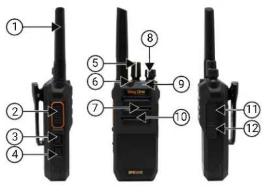
| Action Description |
| 1 Antenna |
| 2 Push-to-Talk (PTT) Button |
| 3 Programmable Side Button 1 |
| 4 Programmable Side Button 2 |
| 5 Channel Selector Knob |
| 6 Emergency Button |
| 7 Speaker |
| 8 On/Off/Volume Control Knob |
| 9 LED Indicator |
| 10 Microphone |
| 11 Accessory Connector |
| 12 USB-C Connector (Charging and Programming) |
2.1
Programmable Buttons
Depending on the duration of a button press, the programmable buttons function differently.
Table 1: Button Press Duration
| Action Description |
| Press Press and release. |
| Long press Press and hold for one second or longer depending on the settings through the Customer Programming Software (CPS). |
2.1.1
Assignable Radio Function
You can program the programmable buttons as shortcuts to the following radio functions through Customer Programming Software (CPS). Contact your dealer for more information.
Table 2: Types of Programmable Functions
| Function Description | |
| All Alert Tones On/Off Allows you to enable or disable the alert tones. | |
| Emergency Off Allows you to terminate an outgoing emergency call. | |
| Emergency On Allows you to set up an emergency call. | |
| Power Level High//Mid/Low Allows you to toggle the transmit power level between high, medium, and low. | |
| Monitor | ● Allows you to monitor the transmission activity of the current channel.● Exits the monitoring mode when the button is released. |
| Nuisance Channel Delete Allows you to temporarily remove unwanted channels from the scan list. | |
| One Touch Access 1–6 Allows you to initiate a one click call corresponding to the call set by the key.One touch access initiates the following features for analog and digital radio.AnalogDTMF-1–DTMF-4DigitalCall Alert, Radio Check, Radio Disable, Radio Enable, and Remote Monitor | |
| Repeater/Talkaround Allows you to switch between using a repeater and communicating directly with another radio. | |
| Scan On/Off Allows you to turn on or off the channel scanning feature. | |
| Squelch Level Tight/Normal/Loose | Allows you to toggle the squelch level between tight, normal, and loose. |
| Scramble On/Off Allows you to toggle scrambling on or off. | |
| VOX On/Off | Allows you to toggle VOX on or off. |
| Zone Toggle Allows you to switch between zones. | |
| Battery Indicator | Allows you to indicate battery strength by using voice prompt. |
| Lone Worker On/Off | Allows you to enable or disable the emergency prompts if there has been no user activity for a predefined time. |
Function Description
| RX Noise Cancellation Allows you to turn on and off the receiving noise cancellation feature. | |
| TX Noise Cancellation Allows you to turn on and off the transmitting noise cancellation feature. | |
| Enhanced Audio Power On/Off | Allows you to turn on and off the enhanced audio power setting for the current channel. The speaker is set to operate at the highest speaker power limit when enhanced audio power is turned on. |
| Sticky Monitor On/off Allows you to monitor a selected channel for all radio traffic until function is disabled. | |
| Battery Saver On/Off Allows you to enable or disable the battery saver feature. | |
2.2
Radio LED Indications
The LED Indicator shows the operational status of your radio. A qualified technician can permanently disable the LED indication through a specific configuration.
Table 3: LED Indication
| Indication Status |
| Solid Red The radio is transmitting. |
| Solid Green The radio is receiving a signal. |
| Blinking Green The radio is scanning. |
| Blinking Red The battery capacity is low. |
| Solid White The radio is charging through USB-C. LED turns off when USB-C charging completes. |
| Blinking White USB-C charging fault. |
Chapter 3
Getting Started
This chapter provides instructions on how to prepare your radio for use.
3.1
Charging the Battery
Your radio is powered by a Lithium-Ion (Li-Ion) battery.
Prerequisites: Turn off your radio when charging.
Procedure:
- To comply with warranty terms and avoid damages, charge the battery using an authorized charger.
Figure 2: Charging through Single-Unit Charger (SUC)
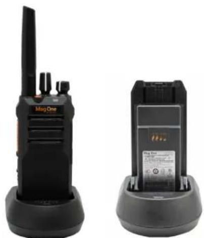
natural_image
Two black Mag One walkieh machines shown from different angles (no visible text or labels on the devices themselves)Figure 3: Charging through USB-C Connector
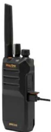
natural_image
Black Min/Qone radio device with visible brand logo and control buttons (no text or symbols on device body)- Charge a new battery for more than five hours before initial use for best performance.
Batteries charge best at room temperature.

NOTE: Charging using the USB-C connector takes approximately 30 % time longer than charging using SUC.
3.2
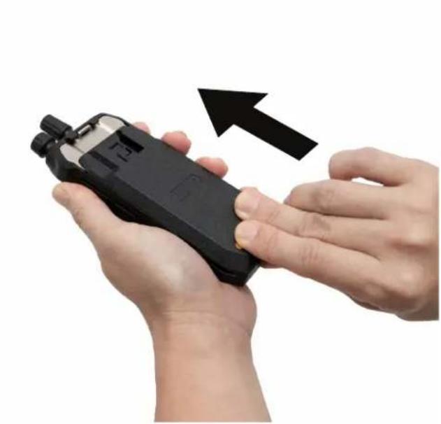
Attaching the Battery
Procedure:
- Align the battery with the rails on the back of the radio.
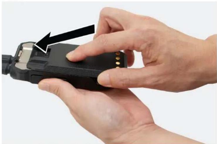
natural_image
Close-up of hands holding a black handheld device with a black arrow pointing to the pad area (no text or symbols visible)- Press the battery firmly and slide upwards till the latch snaps into place.
natural_image
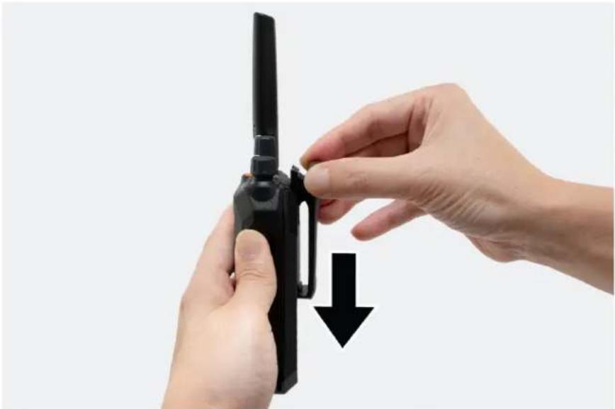
Close-up of hands holding a black handheld device with an arrow pointing to it, against a white background (no text or symbols visible)3.3
Removing the Battery
Procedure:
- Turn off your radio.
- Move the battery latch into unlock position and hold, and slide the battery down.
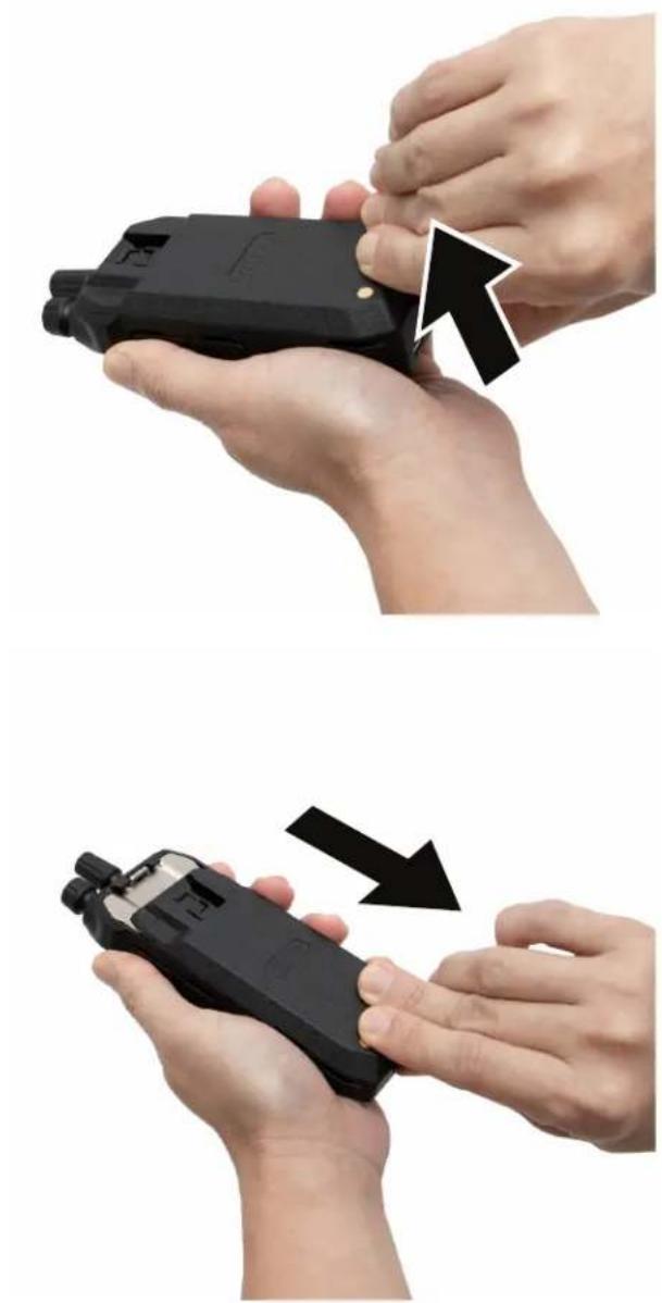
natural_image
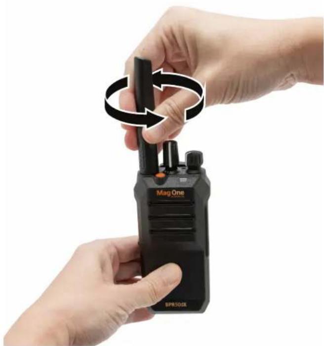
Two-step illustration showing hands holding a black handheld device, with arrows indicating the process (no text or symbols present)3.4
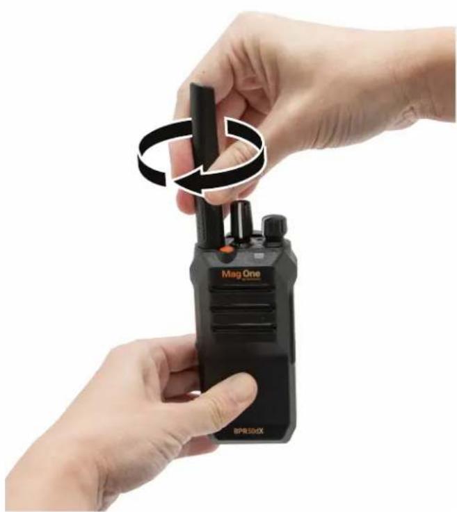
Attaching the Antenna
Procedure:
- Set the antenna in the receptacle.
- Turn the antenna clockwise.
natural_image
Close-up of hands holding a black BPR 50dX walkie-talkie with a circular arrow indicating rotation (no text or symbols on device)
NOTE: Fastening the antenna blocks water and dust from entering the radio.
3.5
Removing the Antenna
Procedure:
- Turn the antenna counterclockwise.
- Remove the antenna from the receptacle.
MN010575A01-AA
Chapter 3: Getting Started
natural_image
Close-up of hands holding a black BPR50GK walkie-talkie with a circular arrow indicating rotation (no text or symbols on device)3.6
Attaching the Belt Clip
Procedure:
Align the rails on the clip with the grooves on the battery and press it downwards until it clicks.
natural_image
Close-up of hands holding a black handheld device with a downward arrow indicating motion (no text or symbols)3.7
Removing the Belt Clip
Procedure:
- To remove the clip, press the belt clip tab away from the battery.
- Slide the clip upwards and away from the radio.
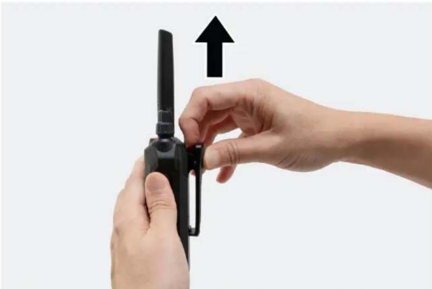
natural_image
Close-up of hands holding a black handheld device with an upward arrow, against a plain background (no text or symbols)3.8
Opening the Dust Cover
Dust cover prevents dust, water stains, and other foreign bodies from entering, damaging the radio, and blocking the jack and the USB-C connector.
Procedure:
Open the dust cover by pulling the cover out.
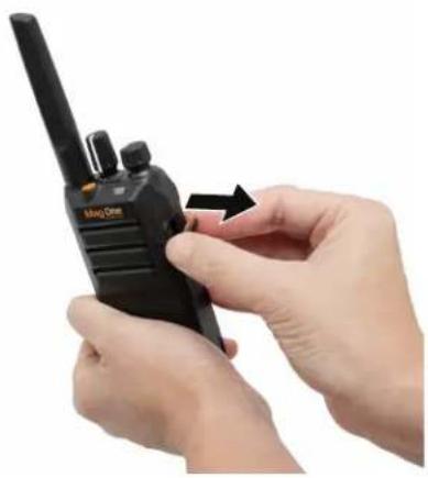
natural_image
Close-up of hands holding a black radio station (no visible text or symbols)
NOTE:
Open the dust cover when attaching the audio accessory, charging cable, or programming cable.
Close the dust cover when you are not charging, programming, or when the audio accessory is not in use.
3.9
Turning the Radio On
Procedure:
Turn the On/Off/Volume knob clockwise until a click sounds.
Result:
If your radio is turned on, your radio shows the following indications:
- A tone sounds.

NOTE: If the Tones/Alerts function is disabled, no tone sounds.
• The green LED illuminates.

NOTE:
If your radio fails to turn on although your battery is charged and properly attached, contact your dealer for assistance.
3.10
Turning the Radio Off
Procedure:
Turn the On/Off/Volume knob counterclockwise until a click sounds.
3.11
Adjusting the Volume
Procedure:
To adjust the volume of your radio, perform one of the following actions:
• To increase the volume, turn the On/Off/Volume Control knob clockwise.
- To decrease the volume, turn the On/Off/Volume Control knob counterclockwise.
3.12
Setting Squelch Levels
Procedure:
Press the programmed Squelch button.
Result:

NOTE:
The default setting is Normal.
The squelch feature is supported in analog mode only.
- If your radio is set to tight squelch, an ascending indicator tone sounds.
- If your radio is set to normal squelch, a flat indicator tone sounds.
- If your radio is set to loose squelch, a descending indicator tone sounds.
Chapter 4
Zone and Channel Selections
A zone is a group of channels. You can program each channel with different features that support different groups of users.
Table 4: Number of Supported Zones and Channels
| Zone Channels | |
| 4 | 64 |
4.1
Selecting Zones
Procedure:
Press the programmed Zone Toggle button.
Result:
Your radio shows the following indications:
- When you switch to Zone 1, one beep tone sounds.
- When you switch to Zone 2, two beep tones sound.
- When you switch to Zone 3, three beep tones sound.
- When you switch to Zone 4, four beep tones sound.
4.2
Selecting Channels
Your radio supports up to 64 channels. Each channel can be programmed with different features that support different groups of users. The radio supports up to four zones, each with 16 channels.
Procedure:
Select channels by rotating the Channel Selector knob.
Your radio indicates the channel number or the programmed channel number through a voice announcement. If the channel is not programmed, an error tone sounds.

NOTE: The radio sounds the voice announcement if the feature is enabled through Customer Programming Software (CPS).
Chapter 5
Calls
Depending on the type of call, you can make, receive, and respond to calls in both Conventional Analog and Digital mode.
5.1
Group Calls
Group Calls are calls from an individual radio to a group of radios. To communicate in a group, your radio must first be configured as a part of the talkgroup.
5.1.1
Making Group Calls
Procedure:
- To select a channel with an active group ID, rotate the Channel Selector knob.
- To call, press the PTT button.
- Wait for the Talk Permit Tone to end, and speak into the microphone.

NOTE: If the selected channel is busy, a busy tone sounds. Your radio is unable to make a call.
- To listen, release the PTT button.
If your radio does not detect voice activity for a predetermined period, the call ends.
5.1.2
Responding to Group Calls
When you receive Group Calls, your radio shows the following indications:
- The green LED illuminates.
- Your radio unmutes and the incoming call sounds through the speaker.
Procedure:
- To respond, press the PTT button.
- Wait for the Talk Permit Tone to end, and speak into the microphone.
- To listen, release the PTT button.
5.2
Private Calls
Private Calls are calls from an individual radio to another individual radio.
5.2.1
Making Private Calls
Procedure:
- To select a channel with an active subscriber ID, rotate the Channel Selector knob.
- To call, press the PTT button.
- Wait for the Talk Permit Tone to end, and speak into the microphone.

NOTE: If the selected channel is busy, a busy tone sounds. Your radio is unable to make a call.
- To listen, release the PTT button.
If your radio does not detect voice activity for a predetermined period, the call ends.
5.2.2
Responding to Private Calls
When you receive Private Calls, your radio shows the following indications:
- The green LED illuminates.
- Your radio unmutes and the incoming call sounds through the speaker.
Procedure:
- To respond, press the PTT button.
- Wait for the Talk Permit Tone to end, and speak into the microphone.
- To listen, release the PTT button.
If your radio does not detect voice activity for a predetermined period, the call ends.
5.3
All Calls
All Calls are one-way calls from an individual radio to all radios on a channel. All Calls are used for making important announcements. The recipients on the channel cannot respond to All Calls.
When you receive All Calls, your radio shows the following indications:
- The green LED illuminates.
- Your radio unmutes and the incoming call sounds through the speaker.
All Calls do not wait for a predetermined period before ending. You can only continue with programmed button functions after the All Call ends. If you switch to a different channel during an All Call, your radio stops receiving the call.
5.3.1
Making All Calls
Procedure:
- To select a channel with an all call ID, rotate the Channel Selector knob.
- To call, press the PTT button.
- Wait for the Talk Permit Tone to end, and speak into the microphone.
Chapter 6
Time-Out Timer
Your system administrator can set the time-out time for a channel through the Customer Programming Software (CPS).
Before the preset timeout timer of the radio expires, a warning tone is emitted based on the preset timeout warning timer time.
When your radio reaches the time-out time, your radio stops transmitting, and the following radio indications occur:
- A continuous alert tone sounds.
• The red LED extinguishes.
To resume transmission, you must release the PTT button and wait for the penalty timer to expire.
Chapter 7
Call Alert Operation
Call Alert paging enables you to alert a specific radio user to call you back.
7.1
Making Call Alert
Your dealer can set up the One Touch Access button to send Call Alert to the desired subscriber ID.
Procedure:
- Select the channel that you want to send the call alert.
- Press the programmed One Touch Access button.
Result:
If the call alert is successful:
- A positive tone sounds when the target radio is detected on the current channel.
If the call alert is unsuccessful: - A negative tone sounds.
7.2
Responding to Call Alerts
When you receive a Call Alert, the following radio indications occur:
- A repetitive tone sounds.
Procedure:
To respond, press the PTT button.
Chapter 8
Radio Enable and Disable
This feature allows you to enable or disable a radio remotely.
For example, you may disable a stolen radio to prevent unauthorized users from using and enabling the radio when it is recovered.
8.1
Initiating Radio Enable
Your dealer can set up the One Touch Access button to send a radio enable command to the desired subscriber ID.
Procedure:
- Select the channel that you want to send the radio enable command.
- Press the programmed One Touch Access button.
Result:
If the radio enable is successful:
- A positive indicator tone sounds.
- The target radio resets.
If the radio enable is unsuccessful: - A negative indicator tone sounds.
8.2
Initiating Radio Disable
Your dealer can set up the One Touch Access button to send a radio disable command to the desired subscriber ID.
Procedure:
- Select the channel that you want to send the radio disable command.
- Press the programmed One Touch Access button.
Result:
If the radio disable is successful:
- A positive indicator tone sounds.
- The target radio blinks green then red LEDs once and the radio is disabled.
- The radio does not respond to user input and is not able to receive or transmit audio.
- Power cycling the radio does not change the radio status.
If the radio disable is unsuccessful:
- A negative indicator tone sounds.
Chapter 9
Radio Check
This feature allows you to determine if another radio is active in a system without disturbing the user of that radio.
9.1
Initiating and Receiving Radio Check
Your dealer can set up the One Touch Access button to send a radio check command to the desired subscriber ID.
Procedure:
- Select the channel that you want to send the radio check command.
- Press the programmed One Touch Access button.
Result:
If the radio check is successful:
- A positive indicator tone sounds.
- The target radio blinks green then red LEDs once and your radio remains muted.
If the radio check is unsuccessful:
- A negative indicator tone sounds.
Chapter 10
Remote Monitor
This feature is used to turn on the microphone of a target radio. You can use this feature to remotely monitor any audible activity surrounding the target radio.
This feature automatically stops after a programmed duration or when there is user operation on the target radio.
10.1
Initiating Remote Monitor
Your dealer can set up the One Touch Access button to send remote monitor command to the desired subscriber ID.
Procedure:
- Select the channel that you want to send the remote monitor command.
- Press the programmed One Touch Access button.
Result:
If the request is successful:
- A positive indicator tone sounds.
- The target radio blinks green then red LEDs once.
- You can hear the audio surrounding the target audio for a programmed duration.
If the request is unsuccessful:
- A negative indicator tone sounds.
Chapter 11
Talkaround
This feature allows you to continue communicating when your repeater is non-operational, or when your radio is out of range from the repeater but within the talk range of other radios.
11.1
Toggling Between Repeater and Talkaround Modes
Procedure:
Press the programmed Repeater/Talkaround button.
When the radio Talkaround mode is off and within the range of the radio, there is no need to connect a repeater to convert the receiving parameters into the transmitting parameters during transmission.

NOTE: Check the channel to enable the Talkaround feature.
Result:
- If a high-pitched ringtone sounds, your radio is in talkaround mode.
- If a medium-pitched ringtone sounds, your radio is in repeater mode. Ensure that the radio is within the repeater range to operate in the repeater mode.
Chapter 12
Monitor Feature
This feature allows you to monitor the activity of the current channel for both analog and digital mode.

NOTE: When the receive noise cancellation is turned on for analog mode, the "white noise" level during monitor is softer.
12.1
Monitoring Channels
Procedure:
- Press and hold the programmed Monitor button.
If the channel is in use:
- You hear radio activity.
- The green LED illuminates.
If the monitored channel is not in use:
- For analog channels, your radio sounds a "white noise".
-
The green LED illuminates.
-
To call, press and hold the PTT button.
- To listen, release the PTT button.
12.2
Sticky Monitor
The Sticky Monitor feature is used to continuously monitor a selected channel for activity.
12.2.1
Setting the Sticky Monitor
Procedure:
Press the programmed Sticky Monitor button.
Result:
When your radio enters the mode:
- A positive tone sounds.
• The green LED illuminates.
When your radio exits the mode:
- A negative tone sounds.
- The green LED extinguishes.
Chapter 13
Scan
Your radio scans through the programmed scan list for the current channel looking for voice activity when you start a scan.
Your radio also performs a dual-mode scan. If you are on a digital channel, and your radio locks onto an analog channel, your radio automatically switches from digital mode to analog mode during the call. If you are on an analog channel, and your radio locks onto a digital channel, your radio automatically switches from analog mode to digital mode during the call.
Table 5: Scan Types
| Type Description | |
| Home Channel Scan (Manual) | Your radio scans all the channels in your scan list assigned to the home channel. |
| Auto Scan (Automatic) Your radio automatically starts scanning when you select a channel or group that has Auto Scan enabled. | |
If you press the PTT button while the radio is scanning, radio transmits on the current channel, home channel, previously selected channel, or the designated channel based on the scan list settings.
13.1
Priority Scan
Priority Scan allows the radio to automatically receive transmission from channels with higher priority. If you want to prioritize a channel, you can enable the Priority Scan feature through the Customer Programming Software (CPS).
13.2
Turning Scan On or Off
Procedure:
Press the programmed Scan button.
Result:
If Scan is enabled:
• A positive tone sounds.
• The green LED blinks.
If Scan is disabled:
• A negative tone sounds.
• The green LED extinguishes.

NOTE: If the auto scan feature is enabled, the radio does not allow you to turn on or off the channel scanning feature using the programmed Scan button.
13.3
Scan Talkback
During scanning, your radio stops on a channel or group where activity is detected. The radio stays on that channel for a programmed duration known as hang time.
Procedure:
- To talk in the ongoing call, press the PTT button during hang time.
- Wait for the Talk Permit Tone to end, and speak into the microphone.
- To listen, release the PTT button.
13.4
Deleting Nuisance Channels
If a channel continually generates unwanted calls or noise (termed a "nuisance" channel), you can temporarily remove the unwanted channel from the scan list. This capability does not apply to the channel designated as the Selected Channel.
Procedure:
- Press the programmed Nuisance Delete button until you hear a tone.
- Release the programmed Nuisance Delete button.
13.5
Restoring Nuisance Channels
Procedure:
Perform one of the following actions:
- Restart your radio.
- Turn off and then turn on the scan.
- Change the channel using the Channel Selector knob.
Chapter 14
Button/Channel Selector Lock
This feature allows you to set the button and channel selector locking mode in the Customer Programming Software (CPS).
The following are the available locking modes:
None
The keys can function and operate normally.
Side Buttons
The programmed function for the side buttons cannot be turned on or off.
Emergency Button
The programmed function for the emergency button cannot be turned on or off.
Channel Selector
Radio switching channels are disabled and cause error prompts.

NOTE: The emergency button, side button, and PTT are functional for normal use.
Chapter 15
Noise Cancellation
The Noise Cancellation feature reduces the effect of surrounding noise that affects the clarity of the intended audio for transmission and reception.

NOTE: When the Receive Noise Cancellation feature is turned on, tones generated by the radio can sound different. Examples of these tones are roger beep, DTMF tones, and squelch tail.
15.1
Setting the Transmit Noise Cancellation
Procedure:
Enable the transmit noise cancellation feature when you are in the noisy environment by pressing the programmed Transmit Noise Cancellation button.
Your radio transmits a clearer audio to the receiver by filtering out the ambient noise.
15.2
Setting the Receive Noise Cancellation
Procedure:
To filter the ambient noise in the received audio, enable the receive noise cancellation feature by pressing the programmed Receive Noise Cancellation button.
Noise is filtered out from the received call. You can hear the caller's voice clearly.
Chapter 16
Scramble
The scramble feature makes your transmissions sound garbled to anyone listening without the same scramble code.

NOTE: The scramble feature is supported in analog mode only.
16.1
Initiating and Receiving Scramble Calls
Procedure:
- Select the channel that you want to toggle scramble on or off.
- Press the programmed Scramble On/Off button.
If scramble is enabled:
• A positive tone sounds.
If scramble is disabled:
- A negative tone sounds.
-
To call, press the PTT button.
-
Your radio is able to receive clear calls if the scramble code is the same as the transmitter.
- If your radio receives a different scramble code, you are not able to hear the call or hear a garbled transmission.
Chapter 17
Lone Worker
This feature prompts an emergency if there is no user activity (button press or channel selector activation) for a predefined time.
Procedure:
Press the programmed Lone Worker button.
When there is no user activity, the radio prewarns you once the inactivity reminder timer expires. You can reset the timer by pressing the PTT button or rotating the channel selector.
If there is still no response from you and the predefined inactivity timer expires, the radio initiates an emergency alarm as programmed by the dealer.

NOTE: This feature is supported in digital mode only.
Chapter 18
Emergency Operation
Emergency Alarms are used to indicate critical situations. You can initiate an Emergency Alarm at any time even when there is an activity on the current channel.
You can only assign one type of Emergency Mode to the Emergency button for each channel.

NOTE:
This feature is supported in Digital mode only.
18.1
Emergency Modes
Your radio supports the following Emergency Modes:
Table 6: Emergency Modes
| Emergency Mode Description | |
| Emergency Alarm An Emergency Alarm is not a voice call. This alarm is an emergency notification sent to radios that are programmed to receive them. | |
| Emergency Alarm with Call | Your radio transmits an Emergency Alarm. When the Emergency Alarm is acknowledged, the group of radios can communicate over the assigned emergency channel. Press and hold the PTT button to talk. |
| Emergency Alarm with Voice to Follow | Your radio transmits an Emergency Alarm. When the Emergency Alarm is acknowledged, your radio microphone is automatically activated which is known as Hot Mic. Hot Mic allows you to communicate with the group of radios without pressing the PTT button. |
| NOTE:If you press and hold the PTT button during the programmed Hot Mic receiving period, your radio proceeds to make a call and stops Hot Mic receiving period timer. Your radio remains in emergency mode after all tries are exhausted.If the Emergency Alarm request fails, the radio enters the Hot Mic directly. | |
| Silent Emergency Alarm | Your radio transmits an emergency notification without any audio or visual indicators. |
| Silent Emergency Alarm with Call | Your radio transmits an emergency notification without any audio or visual indicators. Your radio suppresses all audio and visual indicators of the emergency until you press and hold the PTT button to talk. |
| Silent Emergency Alarm with Voice to Follow | Your radio transmits an emergency notification without any audio or visual indicators. When the Emergency Alarm is acknowledged, the Hot Mic is activated. You can communicate with the group of radios without pressing the PTT button. |
| NOTE: The indicators only appear when you press the PTT button. | |
Your dealer can set the Emergency On or Off function and button-press duration of the Emergency button. Contact your dealer for more information.
18.2
Sending Emergency Alarm
Procedure:
Press the programmed Emergency On button.
Result:
If the alarm is successfully sent:
• The emergency tone sounds.
If the alarm is unsuccessful after all retries:
- A negative tone sounds.
18.3
Sending Emergency Alarms with Call
Procedure:
- Press the programmed Emergency On button.
If the alarm is successfully sent, the emergency tone sounds. - To call, press and hold the PTT button.
- Wait for the Talk Permit Tone to end, and speak into the microphone.
- To listen, release the PTT button.
18.4
Sending Emergency Alarms with Voice to Follow
Procedure:
-
Press the programmed Emergency On button.
If the alarm is successfully sent, the Emergency tone sounds and Hot Mic is activated. -
Speak into the microphone without pressing the PTT button.
Your radio automatically stops transmitting when the hot mic duration expires.
18.5
Emergency Alarms
When you receive an Emergency Alarm, your radio shows the following indications:
- A tone sounds.
• The orange LED blinks
18.6
Exiting Emergency Mode
When you initiate the emergency alarm, the radio automatically exits the emergency mode when you are having the following scenarios:
- An acknowledgment is received from the system (for emergency alarms only).
- All retries to send the alarm are exhausted.
- Turning off your radio. When you turn on your radio, the emergency will not reinitiate automatically.
- Change your current channel.
When you receive an Emergency Alarm, the radio automatically exits the emergency mode when you are having the following scenarios:
- Turning off your radio.
- Change your current channel.
Procedure:
To exit the Emergency Mode, press the programmed Emergency Off button.
Result:
If you successfully exit the Emergency mode, your radio shows the following indications:
- The tone ceases.
- The orange LED extinguishes.
Chapter 19
Auto Power Off
This feature allows you to avoid the radio from being idle for a long time and extend the battery life.
A tone sounds continuously for 10 seconds before the radio shuts down automatically when the Auto Power Off timer has expired.

NOTE:
The radio is idle when there is no user activity such as a button press or rotating the channel selector knob.
If you set the timer to None, the radio disables the Auto Power Off feature.
Chapter 20
Authorized Accessories List
Table 7: Antennas
| Part Number Description | |
| PMAE4117_Mag One, UHF, 400-470 MHz, Whip Antenna | |
| PMAE4118_Mag One, UHF, 450-470 MHz, Stubby Antenna | |
| PMAE4119_1 | Mag One, UHF, 450-527 MHz, Whip Antenna |
| PMAD4164_Mag One, VHF, 136-155 MHz, Whip Antenna | |
| PMAD4165_Mag One, VHF, 152-174 MHz, Whip Antenna | |
Table 8: Battery
| Part Number Description |
| PMNN4847_Mag One Lithium Ion 2200T Battery |
Table 9: Programming Cable
| Part Number Description |
| PMKN4294_Cable, Data, USB-A to USB-C |
| PMKN4311_Cable, Data, USB-C to USB-C |
Table 10: Carry Device
| Part Number Description |
| PMLN8600_Mag One, 2 Inch, Belt Clip |
Table 11: Charger
| Part Number Description |
| PMLN8599_Mag One Charger Desktop Single Unit, Base only, External Power Supply |
Table 12: Earbuds and Earpieces
| Part Number Description |
| PMLN6534_Mag One Earbud with In-Line Microphone/PTT/VOX Switch |
| PMLN6531_Mag One Ear Receiver with In-Line Microphone/PTT/VOX Switch |
| PMLN6532_Mag One Swivel Earpiece with microphone/PTT |
Part Number Description
PMLN6542_ Mag One Ultra-Lightweight Headset with Boom Microphone and In-Line PTT Switch
PMLN6536_2-Wire Surveillance Kit with Quick Disconnect Acoustic Tube
Table 13: Remote Speaker Microphone
| Part Number Description |
| PMMN4092_Mag One Remote Speaker Microphone |
Table 14: Power Supplies and Charging Cables
| Part Number Description |
| PS000150A31 Universal United States/Japan Adapter 5 VDC/1.5 A L6 USB-A Detachable |
| PS000150A32 Universal Europe Adapter 5 VDC/1.5 A L6 USB-A Detachable |
| PS000150A35 Universal Argentina Adapter 5 VDC/1.5 A L6 USB-A Detachable |
| PS000150A36 Universal China Adapter 5 VDC/1.5 A L6 USB-A Detachable |
| PS000150A38 Universal Brazil Adapter 5 VDC/1.5 A L6 USB-A Detachable |
| PMKN4274_USB-A to USB-C Cable (Charging only) |
Table des matières
MOTOROLA, MOTO, MOTOROLA SOLUTIONS, and the Stylized M Logo are trademarks or registered trademarks of Motorola Trademark Holdings, LLC and are used under license. All other trademarks are the property of their respective owners.
Droits de licence
© 2024 Motorola Solutions, Inc. All Rights Reserved
Action Description
natural_image
Two black Mag One walkieh machines shown from different angles (no visible text or labels on the devices themselves)natural_image
Black Min/Qin radio device with visible brand logo and control buttons (no readable text or symbols beyond branding)natural_image
Close-up of hands holding a black handheld device with a white arrow pointing to the handle (no text or symbols visible)natural_image
Close-up of hands holding a black handheld device with an arrow pointing to it, against a white background (no text or symbols visible)3.3
natural_image
Close-up of hands holding a black handheld device with a white arrow pointing to the button (no text or symbols visible)MN010575A01-AA
natural_image
Close-up of hands holding a black handheld device with a hand pointing to it, no visible text or symbols3.4
natural_image
Close-up of hands holding a black Mag One walkie-talkie device (no visible text or symbols on device body)
REMARQUE :
natural_image
Close-up of hands holding a black Mag One walkie-talkie with a circular arrow indicating rotational motion (no text or symbols on device)3.6
natural_image
Close-up of hands holding a black handheld device with a downward arrow indicating a change (no text or symbols visible)3.7
natural_image
Close-up of hands holding a black handheld device with an upward arrow, against a plain background (no text or symbols)3.8
natural_image
Close-up of hands holding a black radio walkie-talkie (no visible text or symbols)
REMARQUE :

- Mag One BPR 50dX Portable Radio User Guide
- Contents
- Legal and Support....5
- Chapter 1: Read Me First....8
- Chapter 2: Radio Overview....9
- Chapter 3: Getting Started....12
- Chapter 4: Zone and Channel Selections.... 20
- Chapter 5: Calls....21
- Chapter 6: Time-Out Timer....23
- Chapter 7: Call Alert Operation....24
- Chapter 8: Radio Enable and Disable....25
- Chapter 9: Radio Check....26
- Chapter 10: Remote Monitor....27
- Chapter 11: Talkaround....28
- Chapter 12: Monitor Feature.... 29
- Chapter 13: Scan....30
- Chapter 14: Button/Channel Selector Lock.... 32
- Chapter 15: Noise Cancellation.... 33
- Chapter 16: Scramble.... 34
- Chapter 17: Lone Worker....35
- Chapter 18: Emergency Operation.... 36
- Legal and Support
- Intellectual Property and Regulatory Notices
- Copyrights
- Trademarks
- License Rights
- Open Source Content
- European Union (EU) and United Kingdom (UK) Waste of Electrical and Electronic Equipment (WEEE) Directive
- Disclaimer
- Legal and Compliance Statements
- Supplier's Declaration of Conformity
- Class B Digital Device
- NOTE:
- Important Safety Information
- RF Energy Exposure and Product Safety Guide for Portable Two-Way Radios
- Notice to Users (FCC)
- Notice to Users (ISED)
- Chapter 1
- Read Me First
- Notations Used in This Manual
- Feature and Service Availability
- Chapter 2
- Radio Overview
- 2.1
- Programmable Buttons
- 2.1.1
- Assignable Radio Function
- 2.2
- Radio LED Indications
- Chapter 3
- Getting Started
- 3.1
- Charging the Battery
- Procedure:
- 3.2
- Attaching the Battery
- 3.3
- Removing the Battery
- 3.4
- Attaching the Antenna
- 3.5
- Removing the Antenna
- Attaching the Belt Clip
- 3.7
- Removing the Belt Clip
- 3.8
- Opening the Dust Cover
- 3.9
- Turning the Radio On
- Result:
- 3.10
- Turning the Radio Off
- 3.11
- Adjusting the Volume
- Setting Squelch Levels
- Chapter 4
- Zone and Channel Selections
- 4.1
- Selecting Zones
- 4.2
- Selecting Channels
- Chapter 5
- Calls
- Group Calls
- Making Group Calls
- Responding to Group Calls
- Private Calls
- 5.2.1
- Making Private Calls
- 5.2.2
- Responding to Private Calls
- 5.3
- All Calls
- 5.3.1
- Making All Calls
- Chapter 6
- Time-Out Timer
- Chapter 7
- Call Alert Operation
- 7.1
- Making Call Alert
- 7.2
- Responding to Call Alerts
- Chapter 8
- Radio Enable and Disable
- 8.1
- Initiating Radio Enable
- 8.2
- Initiating Radio Disable
- Chapter 9
- Radio Check
- Initiating and Receiving Radio Check
- Chapter 10
- Remote Monitor
- Initiating Remote Monitor
- If the request is successful:
- If the request is unsuccessful:
- Chapter 11
- Talkaround
- Toggling Between Repeater and Talkaround Modes
- Chapter 12
- Monitor Feature
- 12.1
- Monitoring Channels
- 12.2
- Sticky Monitor
- 12.2.1
- Setting the Sticky Monitor
- Chapter 13
- Scan
- 13.1
- Priority Scan
- 13.2
- Turning Scan On or Off
- If Scan is disabled:
- 13.3
- Scan Talkback
- 13.4
- Deleting Nuisance Channels
- 13.5
- Restoring Nuisance Channels
- Chapter 14
- Button/Channel Selector Lock
- None
- Side Buttons
- Emergency Button
- Channel Selector
- Chapter 15
- Noise Cancellation
- 15.1
- Setting the Transmit Noise Cancellation
- 15.2
- Setting the Receive Noise Cancellation
- Chapter 16
- Scramble
- Initiating and Receiving Scramble Calls
- Chapter 17
- Lone Worker
- Chapter 18
- Emergency Operation
- 18.1
- Emergency Modes
- 18.2
- Sending Emergency Alarm
- 18.3
- Sending Emergency Alarms with Call
- 18.4
- Sending Emergency Alarms with Voice to Follow
- 18.5
- Emergency Alarms
- 18.6
- Exiting Emergency Mode
- Chapter 19
- Auto Power Off
- Chapter 20
- Authorized Accessories List
- Part Number Description
- Table des matières
- Droits de licence
- REMARQUE :
Brand : MOTOROLA
Model : Mag One BPR 50dX
Category : Radio