C.A 1725 - Odometer CHAUVIN ARNOUX - Free user manual and instructions
Find the device manual for free C.A 1725 CHAUVIN ARNOUX in PDF.


User questions about C.A 1725 CHAUVIN ARNOUX
0 question about this device. Answer the ones you know or ask your own.
Ask a new question about this device
Download the instructions for your Odometer in PDF format for free! Find your manual C.A 1725 - CHAUVIN ARNOUX and take your electronic device back in hand. On this page are published all the documents necessary for the use of your device. C.A 1725 by CHAUVIN ARNOUX.
USER MANUAL C.A 1725 CHAUVIN ARNOUX
1. INTRODUCTION ....4
2. DESCRIPTION ....4
2.1 TACHYMÈTRE 4
2.2 AFFICHEUR 7
3. UTILISATION....9
3.1 MESURES SANS CONTACT 9
3.2 MESURESAVEC CONTACT 9
3.3 MESURES AVEC ENTRÉE EXTERNE 10
4. FONCTIONNEMENT ...... 12
4.1 UNITÉS DE MESURE 12
4.2 ENREGISTREMENT MIN/MAX 13
4.3 MAINTIEN DE LA VALEUR NUMÉRIQUE A L'AFFICHAGE 14
4.4 LISSAGE DE LA MESURE 15
4.5 CHOIX MANUEL DE GAMME 15
4.6 COMPTAGE(C.A1727 uniquement) 16
4.7 ENREGISTREMENT DE MESURES (C.A 1727 uniquement) 16
4.8 ALARMES (C.A 1727 uniquement) 17
4.9 PROGRAMMATION (C.A 1727 uniquement) 18
4.10 EXPLOITATION DES DONNÉES SUR PC (C.A 1727 uniquement) 22
5. ENTRETIEN 23
6. CARACTÉRISTIQUES.... 24
6.1 CARACTÉRISTIQUES GÉNÉRALES 24
6.2 CARACTÉRISTIQUES MÉTROLOGIQUES 25
6.3 CARACTÉRISTIQUES DU CAPTEUR 27
6.4 CARACTÉRISTIQUES DE L'ADAPTATEUR ET SES EMBOUTS 28
7. POUR COMMANDER 29
1. INTRODUCTION
Meanings of the symbols used on the device

WARNING, DANGER!
Refer to the user manual whenever you see this symbol.

This marking certifies compliance with the European "Low Voltage" and "Electromagnetic Compatibility" directives (73/23/CEE and 89/336/CEE).

In the European Union, this product is subject to sorting for the recycling of electrical and electronic equipment in accordance with WEEE directive 2002/96/EC.
You have just purchased a C.A 1725 / C.A 1727 Tachomater, thank you for your confidence.
For best results from your instrument :
- Read these operating instructions carefully.
- Observe the precautions for use.
PRECAUTIONS FOR USE
For measurements without mechanical contact :
Before using the tachometer, check that the front sighting window is perfectly clean.
The minimum detection distance is 1 cm; but take care to avoid the immediate vicinity of any moving part, which might be dangerous for the operator and for the device.
For measurements with mechanical contact :
Keep your hands as far as possible from the moving part.
Do not press too hard, since this might brake the moving part and result in an erroneous measurement. For measurements on shaft ends, position the device as close as possible to the axis of the shaft.
For measurements using an external input :
The use of the external connector requires observance of the rules concerning the interconnection of counting devices and industrial interference.
Use shielded wires connected to an earth that is not exposed to the switching transients of power systems.
The received interference must not exceed the amplitude of the hysteresis fixed in the device (250mV). The external input is limited to a common mode of not more than 50 volts.
ATTENTION :
The external sensor connector uses the same earth as the USB digital output
CONTENTS
1. INTRODUCTION 32
2. DESCRIPTION 32
2.1 TACHOMETER 32
2.2 DISPLAY UNIT 35
3. USE 37
3.1 CONTACT-FREE MEASUREMENTS 37
3.2 MEASUREMENTS WITH CONTACT 37
3.3 MEASUREMENTS WITH EXTERNAL INPUT 38
4. OPERATION 40
4.1 MEASUREMENT UNITS 40
4.2 MIN/MAX RECORDING 41
4.3 HOLD OF THE DIGITAL VALUE ON THE DISPLAY 42
4.4 SMOOTHING OF THE MEASUREMENT 43
4.5 MANUAL CHOICE OF RANGE 43
4.6 COUNTING (C.A1727 only) 44
4.7 RECORDING OF MEASUREMENTS (C.A 1727 only) 44
4.8 ALARMS (C.A 1727 only) 45
4.9 PROGRAMMING (C.A 1727 only) 46
4.10 PROCESSING OF THE DATA ON A PC (C.A 1727 only) 50
5. MAINTENANCE 51
6. CHARACTERISTICS 52
6.1 GENERAL CHARACTERISTICS 52
6.2 METROLOGICAL CHARACTERISTICS 53
6.3 CHARACTERISTICS OF THE SENSOR .... 55
6.4 CHARACTERISTICS OF THE ADAPTER AND ITS END FITTINGS 56
7. TO ORDER 57

1. INTRODUCTION
C.A 1725 and C.A 1727 tachometers, specially designed for industrial applications, measure the speed of rotation of any moving part at a distance or by contact.
CHAUVIN ARNOUX tachometers provide many possibilities in addition to the usual functions:
- Direct reading of the measurement
- Measurement of period, of frequency, of duty cycle, of linear speed
- Measurement by external sensor
- Special functions: smooth, range, hold, etc.
- Dual display: 100,000-point digital and bargraph.
- The C.A 1727 can be parameterized and has a USB link; associated with its specific software, it provides an extensive range of measurement, acquisition, processing, and data analysis possibilities.
2. DESCRIPTION
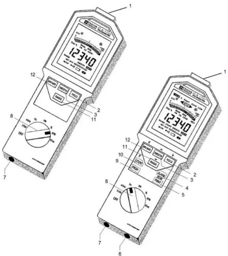
2.1 TACHOMETER
1 Optical sensor
2 HOLD key
- Tore last digital value displayed.
- Disable automatic stop.
key on the C.A 1727 only :
- For programming : shift the selection of the active digit or of the decimal point to the right.
3 SMOOTH key
- Smooth the measurements.
key on the C.A 1727 only : - For programming : increment the active digit.
ALARM key on the C.A 1727 only :
- Activate the audible and visual alarms.
- Program the alarm thresholds.
5 PRINT key on the C.A 1727 only :
- Command recording of the measurements in memory.
SCAN key on the C.A 1727 only :
- Program the rate at which the measurements are recorded in memory.
6 USB output connector, on the C.A 1727 only.
7 Connector for external input.
8 Rotary switch.
9 key on the C.A 1727 only :
- Programming.
- Initialize the program memory.
10 COUNT key on the C.A 1727 only :
- Event counter.
key on the C.A 1727 only :
- Program the scale factor : coefficient K.
11 key RANGE
- Manual or automatic change of range.
- Extend the measurement range at low frequency.
key on the C.A 1727 only :
- For programming : decrement the digit.
12 MIN MAX key
- Record minima and maxima.
- Disable the buzzer.
key on the C.A 1727 only :
- For programming : shift the selection of the active digit or of the decimal point to the left.

text_image
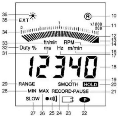
12340 OFF HOLD RANGE INJ MAX TROCKET HOLD 2 3 11 8 7 6 5 4 3 2 1 12340 HOLD COUNT REDUCE HOLD WIP POUND REDUCE HOLD PRINT PRINT TGA-COM PRINT PRINT PRINT PRINT PRINT PRINT PRINT PRINT PRINT PRINT PRINT PRINT PRINT PRINT PRINT PRINT PRINT PRINT PRINT PRINT PRINT PRINT PRINT PRINT PRINT PRINT PRINT PRINT PRINT PRINT PRINT PRINT PRINT PRINT PRINT PRINT PRINT PRINT PRINT PRINT PRINT PRINT PRINT PRINT PRINT PRINT PRINT PRINT PRINT PRINT PRINT PRINT PRINT PRINT PRINT PRINT PRINT PRINT PRINT PRINT PRINT PRINT PRINT PRINT PRINT PRINT PRINT PRINT2.2 DISPLAY UNIT
1 Programming mode, on the C.A 1727 only.
2 Low threshold crossed, on the C.A 1727 only.
3 Full-scale coefficient K, on the C.A 1727 only.
4 Low threshold function, on the C.A 1727 only.
5 Memory write function, on the C.A 1727 only.
6 High threshold function, on the C.A 1727 only.
7 High threshold crossed, on the C.A 1727 only.
8 Rate of recording of measurements function, on the C.A 1727 only.
9 Transmission or reception in progress, on the C.A 1727 only.
10 Flashing indicator of operation of the infrared sensor.
11 Full-scale value of the bargraph (from 2 to 200 x 1000).
12 Analogue display by bargraph.
13 Arrowhead(s) indicating overshoot of end of scale.
14 Speed of rotation - Revolutions per minute
15 Revolutions: count of number of revolutions, on the C.A 1727 only.
16 metres per minute: linear speed.
17 Hertz: frequency.
18 Digital display, 5 digits.
19 Measurements in smoothed values.
20 Frozen display of the last measurement.
21 Recording paused.
22 Device in permanent operation.
23 Battery charge indicator.
24 MIN/MAX recording.
25 Buzzer active indicator.
26 Reading of MAX memory.
27 Measurement range extended to 0.1 Hz.
28 Reading of MIN memory.
29 Disable automatic change of range.
30 Counting function, on the C.A 1727 only.
31 Millisecond: period.
32 Duty cycle.
33 · ft/min: feet per minute - linear speed (in English).
- tr/min: revolutions per minute - speed of rotation.
34 Graduated fixed scale.
35 Measurement by external connector.
36 Optical transmitter in action.

text_image
36 35 EXT 34 0 1 x1000 200 10 11 12 13 14 Duty % ftr/min RPM ms Hz m/min 16 17 18 19 29 RANGE SMOOTH HOLD 20 28 MIN MAX RECORD-PAUSE 21 SLOW ●●●● P 27 26 25 24 23 22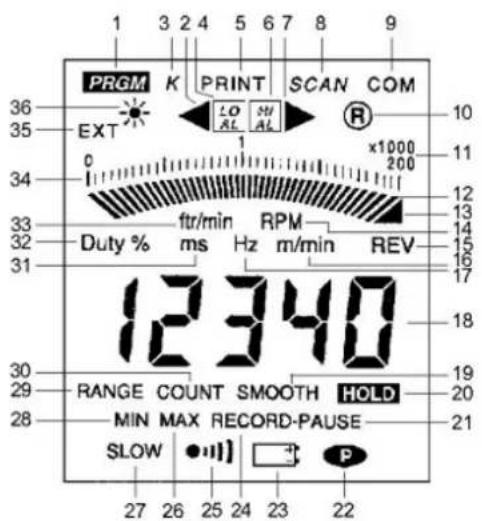
text_image
PRGM K PRINT SCAN COM EXT LO AL R x1000 200 Duty % ftr/min RPM REV 12340 ms Hz m/min REV 18 RANGE COUNT SMOOTH HOLD 19 MIN MAX RECORD-PAUSE 20 SLOW P 21 27 26 25 24 23 223. USE
3.1 CONTACT-FREE MEASUREMENTS
The contact-free measurement is made by the optical sensor built into the device. This sensor, placed in the front of the device, comprises a frequency-modulated infrared transmitter.
Before making any measurement, it is necessary to prepare the revolving target of which the speed is to be determined.
Check that the surface sighted is free of spurious reflections that might be counted in addition to the pulses from the reflecting adhesive. Proceed as follows: before applying the adhesive used to make the measurement, turn the target and check that when it is sighted the reading remains at ---. If not, it will be necessary to cover the entire surface of the target with a mat black medium.
When the target is correct, apply a reflecting adhesive tape on it, along the longest available radius. On small targets, the area covered by the adhesive tape must be less than 50% of the total area of the rotating part.
Start the target turning, aim the front of the device at it, and check that the measurement OK symbol flashes regularly.
The distance between the sensor and the target must be between 1 and 50cm.
The measurement angle of 30^ ( 15^ on either side of the perpendicular to the target) is convenient for aiming purposes.
During measurements of low speeds, very small movements of the device may make the measurement unstable: if this happens, we recommend placing the device on a stable support. There is a nut on the underside of the device for attachment to a tripod or similar support.
3.2 MEASUREMENTS WITH CONTACT
The mechanical adapter and its 3 end fittings allow measurement by contact on a shaft end or on a surface in linear motion.
It is placed in front of the sighting window of the optical sensor and accepts one of the following 3 end fittings:
- An elastomer cone with a tip that can be used for shaft end measurements (minimum diameter: 5mm).
- An elastomer cylinder that can be used for measurements on shafts with flat ends or shafts smaller than 5mm.
- An elastomer wheel for linear speed measurements (1 revolution of the wheel = 0.1m).
The end fitting must be pressed against the moving part just hard enough to drive it without slippage.
The adapter is attached to the front of the tachometer housing, in front of the sighting window. It automatically locks in position when pushed home.
- Fitting
To attach the adapter, align the three lugs on the inside of the adapter with the three recesses of the sighting window of the housing and turn anticlockwise.
- Removal
To remove it, pull the adapter outward until the locking tabs are clear, then turn clockwise.

3.3 MEASUREMENTS WITH EXTERNAL INPUT
The device has a 4-contact connector that can be used to connect an external source of which you wish to measure the speed, the frequency, the period, the duty cycle, etc.
In order to inform the tachometer that the measurement is available on the external input, it is necessary to short-circuit contacts 1 and 4.
Operation using the external input is indicated on the display unit by the extinction of the transmission symbol and the display of EXT.
Wiring

text_image
Connector of the tachometer 2- measurement input (± 20VC max.) seen from contact side 3- see below 1- earth 4- to be sConnecting 1 to contact 3 makes it possible to adapt the triggering threshold to the nature of the signals.
Contacts 1 and 3 not connected
For operation with 0 - 5V TTL signals.
The triggering threshold is +1.1V (at 1kHz).
To avoid the problems due to noise often present in an industrial environment, the threshold has a hysteresis of 250mV.
Contacts 1 and 3 connected
For operation with signals balanced with respect to earth.
This function allows direct measurement using a variable-reluctance magnetic sensor or the output of an alternator.
The triggering threshold is 300mV (at 1kHz), with a hysteresis of 250mV. The residual noise superimposed on the signal to be measured must be less than 250mV so as not to interfere with the measurement when the threshold is crossed.
ATTENTION :
The maximum voltage to input no. 2 must not exceed ± 20Vp. The earth of the external input connected is electrically connected to the earth of the USB digital output.
The external input must be used for the measurement of slow signals, from 0.1Hz. The table below sums up the characteristics of this input.
| Measurement frequency range from 1Hz to 10kHzfrom 0.1Hz to 10kHz in expanded range | |
| Functions available same as optical sensor | |
| Accuracy same as optical sensor | |
| Input impedance ≥ 75kΩ | |
| Balanced signals mode 300mV ± 90mV at 1kHzThresholds 600mV ± 160mV at 10kHzHysteresis 250mV ± 80mV | |
| TTL signals mode 1.1V ± 150mV to 1kHzThresholds 2.2V ± 300mV to 10kHzHysteresis 250mV ± 80mV | |
| Maximum voltage ± 20V peak | |
| Acceptable overload (1second) 250Vrms |
Example of DUTY CYCLE Measurement on EXTERNAL INPUT
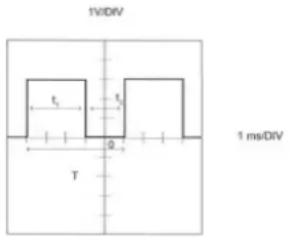
When the external input is used, the FRB connector provided with the device must be connected to the source of the signal to be measured, then to the connector marked EXT. Consider a signal like the one shown in the figure below:
text_image
1V:DIV t₁ t₂ 0 T 1 ms:DIVHere, the frequency of the signals is given by the formula :
$$ \begin{array}{l} f = \frac {1}{T} \ T = 5 \times 1 \mathrm{ms} = 5 \mathrm{ms} \ \text { so } f = \frac {1}{5 . 1 0 ^ {- 3}} = 2 0 0 \mathrm{Hz} \ \end{array} $$

The duty cycle is given by :
$$ D u t y = \frac {t _ {1}}{t _ {1} + t _ {2}} $$
or, in %. Duty % = _1x 100 t_1 + t_2
Here, we have :
$$ \text{Duty} \% = \frac {3}{x - 100} = 60 \% ][ 3 + 2 $$
To make this measurement with the C.A 1725 or C.A 1727 tachometer, you must:
1) Check the amplitude of the input signal to the device. This serves to determine what threshold must be set. Here, the amplitude is greater than +1.1 V, so contacts 1 and 3 of the FRB connector must not be interconnected.
2) Switch the tachometer on by setting the rotary switch to "%".
3) The display unit indicates directly the result mentioned above.
If there is no reading on the display unit, check that the amplitude of the signal to be measured is above the triggering threshold.
4. OPERATION
4.1 MEASUREMENT UNITS
The table below indicates the display capacity for each function.
| Function Display | |
| tr/mn or RPM 60.000 to 99999 | |
| m/mn (K = 0.1) 6.0000 to 99999 | |
| ft/mn (K = 0.328) 19.680 to 99999 | |
| Hz 1.0000 to 9999.9 | |
| Period (ms) 0.1000 to 999.99 | |
| Duty cycle % 0.1 to 99.9 | |
| Counter 0 to 99999 | |
In a measurement extended to 0.1Hz using the Ext input, the minimum values are divided by 10.
On/Off function:
If this function is not overridden when the device is switched on (see below), the device is switched off automatically if one of the following has not occurred during the last 5 minutes:
- Press of a key,
- Or change of setting of the rotary switch,
- Or interrogation of the digital output.
Before switching off automatically, the tachometer emits an audible beep.
Special functions :
The following special functions are obtained when a key is kept pressed when the device is switched on:
| KEY FUNCTION | |
| No key pressed Switched on for 5 minutes | |
 | Switched on for an indefinite duration ^ appears on the display unit appears on the display unit |
 | Switched on without buzzerThe symbol does therefore not appear |
 | Initialization of all values contained in the program memory.The display unit indicates „Init“ |
 | Measurement down to 0.1HzSLOW lights on the display unit. |
4.2 MIN / MAX RECORDING
The recording function can be used to store the minimum and maximum values of the measurements. Pressing the MIN MAX key switches the device into recording mode. The RECORD and symbols are displayed. The automatic switching off function is disabled.
MIN value
Initially, the value store is OL (OVER LOAD). When the MIN MAX key is pressed, the value displayed is stored in the MIN register.
Whenever a value below the value stored in the register is measured, it is transferred to the MIN register and 1kHz audible beep is emitted.
MAX value
The value stored at the start is zero. A measured value greater than the value stored in the register leads to an update.
Each time the content of the MAX memory is modified, a 2 kHz audible beep is emitted.
Reading of the MIN/MAX memories
The values contained in the MIN and MAX registers can be displayed by successive presses on MIN MAX
The circular display indicates in turn the MAX, the MIN and the current measurement value.
Recording continues during the reading; the bargraph indicates the instantaneous measurement. NB: if the "SMOOTH" function is activated, the MAX and MIN are determined from the smoothed values.
Stopping the MIN/MAX recording function
The recording function is stopped either by a long press on the MIN MAX key or by turning the switch.
Remark : The MIN/MAX functions is not available in counting mode.

4.3 HOLD OF THE DIGITAL VALUE ON THE DISPLAY
By a brief press on the HOLD key (when not in programming mode).
Pressing HOLD freezes the digital display on the last measurement displayed; the bargraph continues to indicate the instantaneous measurement value. The display indicates HOLD. Pressing the HOLD key again restores the display of the instantaneous measurements, and HOLD disappears from the display unit.
HOLD
in the „MIN/MAX“ recording mode
When the key is pressed while RECORD is displayed :
- The HOLD and PAUSE symbols are displayed.
- Recording stops and the values contained in the MIN and MAX memories are the last values
before
HOLD - The digital display unit indicates the last measurement value, or else the MIN or MAX value if the device was reading them back.
- The bargraph continues to indicate the current measurement.
Pressing the key again causes the recording of the MIN and of the MAX to resume :
- The HOLD and PAUSE symbols remain displayed.
- The display unit indicates the measurement in progress or the content of the MIN/MAX memory being read back.
- The device is once again in MIN/MAX mode, but the memories have not been reset and they
contain the MIN and MAX values present before the HOLD
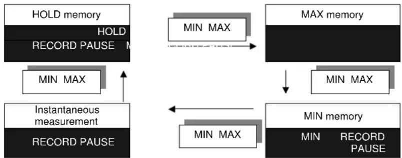
When the HOLD and RECORD - PAUSE symbols are displayed, it is always possible to display, in a circular manner, the values in the memories and the instantaneous measurement value, by brief
presses on the .MIN MAX
flowchart
graph TD
    A["HOLD memory"] --> B["RECORD PAUSE"]
    B --> C["MIN MAX"]
    C --> D["MAX memory"]
    D --> E["MIN MAX"]
    E --> F["MIN MAX"]
    F --> G["MIN MAX"]
    G --> H["MIN MAX"]
    H --> I["Instantaneous measurement"]
    I --> J["RECORD PAUSE"]
    J --> K["MIN MAX"]
    K --> L["MAX memory"]
    L --> M["MIN MAX"]
    M --> N["MIN MAX"]
The bargraph always indicates the current measurement value.
Whatever display is in progress :
- A brief press on the HOLD key restores recording without resetting the memories.
- A long press on the MIN MAX key stops recording.
Application :
When the tachometer is used in a place where it is difficult or impossible to read the display unit, the HOLD function can be used in conjunction with MIN/MAX recording to store the minimum and maximum values reached.
4.4 SMOOTHING OF THE MEASUREMENT
Pressing the SMOOTH key starts the smoothing of the measurement (SMOOTH displayed). The digital value indicated is then the sliding average of the last 10 measurements (approximately 5 seconds). The bargraph always indicates the instantaneous measurement.
In MIN/MAX recording, if the SMOOTH symbol is displayed, the values recorded are the smoothed values.
Activating or deactivating the SMOOTH mode during MIN/MAX recording cancels the MIN and MAX values already stored.
Remark: The SMOOTH function has no effect on the counting function.
4.5 MANUAL CHOICE OF RANGE
When the device is switched on, or during a change of function, the device automatically selects the most appropriate measurement range. Each function has 4 or 5 ranges, except for the duty cycle function (2 ranges).
In automatic operation, the digital display unit has a display capacity of 20,000 points and the possible full-scale values of the bargraph are 2, 20, 200, 2000, 20,000, and 200,000.
In the automatic mode, the digital display unit switches to a higher range when 20,000 points is reached.
A first brief press (<2 s) on the RANGE key freezes the current measurement range. RANGE appears on the display unit. The digital indicator then has a display capacity of 100,000 points.
Each new press on the RANGE key switches both displays (bargraph and digital) to the next
higher range. From the highest range (20,000) the RANGE key switches the device to the 2 range.
To exit from the manual range change mode, press the RANGE key for more than 2 seconds.
Remark:
If the measurement value exceeds the display capacity, the display unit indicates OL and the range overshoot arrow appears to the right of the bargraph.
ATTENTION :
The functions described in the paragraphs that follow are available only on the C.A 1727.

4.6 COUNTING (C.A 1727 ONLY)
Press the COUNT key to switch the device into the event counting mode. COUNT appears on the display unit and the measurement units are changed (see table below).
| Measurements mode COUNT mode | |
| tr/min rev (revolution) | |
| m/min m (metre) | |
| RPMREV (revolution) | |
| ft/min ft (foot) | |
| Hz / | |
| ms / | |
| Duty % / | |
The Hz, ms, and % symbols disappear. There is no longer a measurement unit displayed; the device simply counts the number of pulses received.
A press on the HOLD key stops the counting. A second press causes the counting that was paused to resume.
When 99,999 events are reached, the display changes to OL.
To exit from the counting mode, simply press the COUNT key again. The counter is reset by 2 successive presses on the keyUNT
Remarks:
- As standard, the device counts metres or feet, with a measurement resolution equal to the circumference of the end fitting used, 0.1m or 0.328ft. This resolution can be changed by changing the value of K. - In the counting mode, the recording, change of range, and smoothing functions are not available.
4.7 RECORDING OF MEASUREMENTS (C.A 1727 ONLY)
The PRINT key can be used to record the value displayed.
- with HOLD :
The record will be the last value displayed, preceded by HOLD.
- with MIN/MAX recording :
When the device is in recording mode (RECORD, MIN or MAX on the screen), the PRINT command records the MIN, the MAX and the current measurement.
- with record MIN MAX + HOLD :
In this mode (RECORD - PAUSE and HOLD symbols displayed), the PRINT command records the following four parameters:
- The HOLD value
- The value contained in the MIN register
- The value contained in the MAX register
- The current measurement value.
- with SMOOTH
The value recorded is then the smoothed value, when this function is displayed (SMOOTH).
For the entire duration of recording of the information, the PRINT and COM symbols are displayed.
When the Scanning function is programmed (see "Recording Interval"), pressing the PRINT key starts the measurement recording cycle according to the interval programmed. The SCAN symbol is displayed and remains displayed for the entire duration of the scanning operation. PRINT and COM are displayed each time data are transmitted to the memory.
A second press on the key interrupts the scanning; the last data are transmitted and the SCAN, PRINT, and COM symbols go off.
Further presses on the key alternately start and stop the function.
4.8 ALARMS (C.A 1727 ONLY)
When thresholds have been programmed, a brief press on the key activates detection of the croosing of these thresholds by the measurement.
The or symbol is displayed, or both, according to the type of threshold programmed. The operation of the device is summed up in the table below.
| Digital measurement > low threshold (LO AL) | No action |
| Digital measurement < high threshold (HI AL) | No action |
| Digital measurement < low threshold | Continuous buzzer at 1 kHzDisplay of [IMAGE] |
| Digital measurement > high threshold | Continuous buzzer at 4 kHzDisplay of [IMAGE] |
| If the value of LO AL is greater than the value of HI AL, this operation is reversed. The buzzer is triggered (at 2 kHz) in the central zone between the HI AL and LO AL values. | |
If no threshold value has been programmed, an audible beep is emitted when the key is pressed and the command is not accepted.
To stop the Alarm function, press the ALARM key again.

4.9 PROGRAMMING (C.A 1727 ONLY)
The device lets you program four values to define:
- A low alarm threshold (LO AL).
- A high alarm threshold (HI AL).
- A multiplier coefficient (K).
- A recording interval (SCAN).
A press on the key switches the C.A 1727 into programming mode; PRGM is displayed.
In the programming mode, the C.A 1727 no longer makes measurements; the bargraph is off, the optical transmitter is off.
The functions of the keys become those indicated in yellow above each key.
| Functions of the keys in Functions of measurement mode pogramming mode | the keys in mode |
 |  Shift left Shift left |
 |  Shift right Shift right |
 |  Increment active digit Increment active digit |
 |  Decrement active digit Decrement active digit |
 |  Program scanning Program scanning |
 |  Program threshold Program threshold |
 |  Program coefficient K Program coefficient K |
Procedure
The explanations below describe the procedure to follow to program the various memories of the C.A 1727. These stages are common to all functions: scanning, thresholds, and coefficient K. The "Alarm thresholds" to "Recording interval" paragraphs describe the features specific to each function. Before switching the C.A 1727 to programming mode, you must choose, on the rotary switch, the function of which you wish to program the values.
Pressing the PRGM key displays the PRGM symbol, switches off the bargraph, and displays "----".
The second stage is choosing the function to be programmed, by pressing the: SCAN ; or key. ALARM
The digital display unit then indicates the value contained in the memory, or "----" if nothing has yet been programmed (when programming for the first time, or if the last programming disabled this function). At the same time, the left-hand digit (or dash) flashes.
Programming is on 100,000 points (0 to 99,999), and there are 5 possible positions of the decimal point for the alarm thresholds (the decimal point is fixed for K and the SCAN interval has no decimal point). A value is entered in memory as follows:
A/ writing of all digits of the desired value, without taking account of the decimal point.
B/ positioning of the decimal point.
A/ Writing of a number without a decimal point:
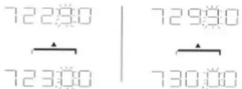
When the dashes are displayed, pressing a horizontal shift key replaces the dashes by zeros, by the value previously recorded, or by the extreme value possible compatible with the function. The value of the active digit (flashing) is incremented or decremented by pressing the |→| or .→|key, respectively. Increasing a digit from 9 to 0 automatically increments the digit (or digits) to the left of it, while decreasing a digit from 0 to 9 automatically decrements the digit (or digits) to the left of it.
Example :
- Display
- Key
- Display
text_image
722.00 | 729.00 723.00 | 730.00If during the incrementation or decrementation operations the maximum display capacity is exceeded, the display unit reverts to displaying five dashes.
The and keys are used to shift the active digit (flashing), the one to be programmed, to the left or to the right, respectively.
When the left-hand digit is active, pressing the key causes the appearance of the five dashes or of the value previously recorded in memory.
Validation is effected by pressing the PRGM key or another programming key (e.g. SCAN). Validating "----" stops and cancels all programming.
B/ Positioning of the decimal point:
To activate the decimal point, you must press the key until the right-hand digit flashes. Pressing the key again activates the shifting of the decimal point. The and/ or key can then be pressed to set the decimal point to desired position.
Example :
- Display
- Key
- Display
- Key
- Display
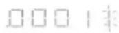




When the decimal point is located on the left or right side of the display unit, pressing the or key, respectively, causes the appearance of „----“.

To return the decimal point to the display unit, simply press the or key, depending
on whether the decimal point exited on the left or right, respectively. Because there are five possible positions of the decimal point, the resolution of the programming may be finer than the resolution of the measurement. When this is the case, the crossing of the alarm thresholds is still determined according to the true measurement resolution.
To exit from the programming mode, and to validate:
Either press the PRGM . You leave the programming mode and PRGM goes off.
- Or switch to another programming function by pressing ALARM, or key, SCAN
- Or turn the switch to any other position except "OFF". The device then returns to measurement mode (switching to "OFF" disables validation and entails the loss of the current values; the values previously recorded remain valid).
The information contained in memory is read back in the same way as it is programmed, except that
the , , and keys must not be used.
Alarm thresholds (C.A 1727 only)
Two thresholds can be set. To program these values, press the ALARM key when in programming mode.
A first press on the ALARM key results in the display of and lets you program the low threshold.
A second press on the ALARM key validates the low threshold (LO AL), displays H AL and lets you prigram the high threshold (HI AL).
When a threshold is programmed and the ALARM function is activated, the corresponding symbol appears on the display in measurement mode and the measured value is compared to this value at all times. An overshoot of the threshold results in the display of the corresponding symbol and activates the buzzer (see the use of this function in the "ALARM" section).
When one or both alarm thresholds have been programmed and activated, it or they appear on the bargraph in reverse video (with respect to the measurement): black if the deviation is below the threshold, white if the deviation is above the alarm threshold, flashing (4 Hz) if the measurement is equal to the threshold value.
Coefficient K (C.A 1727 only)
Coefficient K is a multiplier applied to the raw measurement value in order to obtain a display that can be used as is.
Examples:
- Programming of a gearbox ratio. This makes it possible to display, directly, the output speed of a reduction gear while measuring the input speed.
- Flow measurements. A flow meter delivers one pulse every 2 m3. Setting a coefficient of K = 2 makes the reading in Hz equal to the flow rate in m3 per second. The COUNT function delivers, in addition, the total volume that has flowed through the pipe.
Pressing the key in the PRGM mode lets you program the value of coefficient K.
When a coefficient other than the initial value has been programmed, the symbol K appears on the display unit in the measurement mode. The digital display and the bargraph then both apply multiplier coefficient K.
The K symbol can be made to disappear only by reprogramming the original value of coefficient K (see the table below).
The programming of K is limited to values between 99.999 and 0.010. No other values are accepted.
| Measurement Counting Original K | |
| K in tr/mn K in revolution's 1 | |
| K in m/min K in m 0.1 | |
| K in RPM K in REV 1 | |
| K in ft/min K in ft 0.328 | |
| K in kHz, ms, % K in pulse count 1 |
Programming a coefficient K does not change the maximum measurement and display limits (0.1 to 10,000Hz and 0 to 99,999 points).
The table below indicates the frequency limits as a function of the programmed value of coefficient K (it is assumed that the external input connector is used). Beyond these limits, the display indicates "OL" for an overshoot and "----" for an undershoot.
| Measurement unit Programmed coefficient K | |||
| 0.01 99.999 | |||
| Hz | MAX input freq., 9999.9Hz giving a MAX display of | 1000Hz | |
| 99999pts 99999pts | |||
| MIN input freq., giving a MIN display of | 0.1Hz | 0.1Hz | |
| 0.0010pts | 9999pts | ||
| tr/min or RPM | MAX input freq., 10.000Hz giving a MAX display of | 16.666Hz | |
| 6000.0pts | 99999pts | ||
| m/min | MIN input freq., giving a MIN display of | 0.1Hz | 0.1Hz |
| 0.0600pts | 59999pts | ||
| Measurement unit Programmed coefficient K | |||
| 0.033 | 32.81 | ||
| ft/min | MAX input freq., 10000Hz giving a MAX display of | 50.8Hz 19800pts 99999pts | |
| 1ft = 0.3048cm 1m = 3.281ft | MIN input freq., giving a MIN display of | 0.1Hz 0.1980pts | 0.1Hz 196.86pts |
Recording interval (C.A 1727 only)
The scanning function is used to make measurements at a preset rhythm and automatically record the results. It is possible to store up to 4000 points.
This function is programmed by pressing the SCAN key in PRGM mode. The SCAN symbol is displayed.
The value programmed is the number of seconds between two successive records. The limits are 10 seconds minimum and 99,999 seconds maximum (approximately 27 hours).
In measurement mode, recording is started (stopped) by pressing the key; the display of the
PRINT and SCAN symbols confirms that recording is in progress (see "RECORDING").
If the recording interval exceeds five minutes, the optical transmitter of the device is switched off between measurement ( -- symbol off on the display unit), then switched back on 2 seconds before the next measurement.
The automatic stop function of the C.A 1727 is disabled for the duration of the scanning function. The P symbol is displayed.
4.10 PROCESSING OF THE DATA ON A PC (C.A 1727 ONLY)
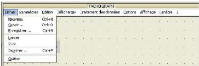
TACHOGRAPH software can be used for two-way management of the data contained in the C.A 1727. It allows the acquisition, processing, and analysis of the measurements made by the C.A 1727 tachometer, and the transfer of results files to the hard disc of a PC. It can be used to translate them into a format compatible with EXCEL, to allow the end user to perform any desired digital processing of the results. It allows the transfer and display of the programming parameters of the device.
Digital processing of the results, such as calculation of the mean value, of the integral (position), or of the derivative (acceleration), and the corresponding display in graph form are included in the TACHOGRAPH software.
The editing functions available in the graph window are:
Addition of Min + text1, addition of Max + text2, rename the graph.
The display functions available for each graph are:
- Parameterizing of the scale, of the colours, addition of the grid (reticule), of two cursors, of a key with display of the delta between the cursors, of the Zoom + and - function.
The parameterizing functions for the start of acquisition are:
- Parameterizing of the RS232 communication interface, of the Scan or rate of reading of the measurement, of the recording thresholds, of the alarms.
Example of menu on the screen of the PC: The File menu
Example of menu on the screen of the PC : The help menu (?)

The tachometer requires no special maintenance other than changing the battery and cleaning the housing.
- Adjustments
The device has no internal adjustments. Measurement accuracy is ensured by a highly stable crystal oscillator.
- Cleaning the housing
Clean with a cloth moistened with soapy water, then plain water.
A dirty sighting window can severely impair the sighting characteristics, making any measurement impossible or unstable.
- Cleaning the mechanical kit
Clean with a cloth moistened with soapy water, then plain water.
The use of alcohol or of another solvent might irreversibly damage the mechanical adapter by degrading its lubrication.
- Replacement of the battery
When the battery symbol appears on the display unit, the battery must be replaced.
Set the switch to "OFF".
- Open the battery compartment, located on the back of the device. Unscrew the screw using a tool (coin, etc.)
- Remove the battery and insert a new one in its place, taking care with the polarity. Use a 6LF22 or similar alkaline battery.
- Close the cover of the compartment and tighten the screw moderately.
- Storage
For extended periods of non-use, we recommend removing the battery from the device and storing it separately.
- Metrological check
Like all measuring or testing devices, the instrument must be checked regularly.
This instrument should be checked at least once a year. For checks and calibrations, contact one of our accredited metrology laboratories (information and contact details available on request), at our Chauvin Arnoux subsidiary or the branch in your country.

- Repair
For all repairs before or after expiry of warranty, please return the device to your distributor.
- Warranty
Our warranty is valid, except as otherwise expressly stipulated, for twelve months, counting from the date on which the equipment is made available (extract from our General Terms of Sale, communicated on request).
The warranty does not apply following:
- inappropriate use of the equipment or use with incompatible equipment;
- modifications made to the equipment without the explicit permission of the manufacturer's technical staff;
- work done on the device by a person not approved by the manufacturer;
- adaptation to a particular application not anticipated in the definition of the equipment or not indicated in the operating instructions;
- damage by shocks, falls, or floods.
6. CHARACTERISTICS
6.1 GENERAL CHARACTERISTICS
- Device: Tachometer with optical sensor, external input, and USB input / output (C.A 1727 only).
- Functions: Measurements of rpm, m/min, Hz, ms, and duty cycle.
- Recording : 4000 points, recording interval from 10 to 99 999s.
- Housing: Polycarbonate, sensor lens made of methacrylate.
- Dimensions: 21 x 72 x 47mm
- Mass: Approximately 250g.
- Tightness: IP51 as per standard IEC 60529.
- Electromagnetic compatibility: In conformity with EMC requirements as per NF EN61326-1
- Safety: in conformity with IEC 61010-1
- Power supply:
- 6LF22 or equivalent 9V alkaline battery.
- Mean battery life: - 250 5-minute measurements with optical sensor.
- 600 5-minute measurements with external input.
- Environment:
- Storage: -20 to +70°C / 95% RH max without condensation.
- operation: 0°C to +55°C / 90% RH without condensation.
6.2 METROLOGICAL CHARACTERISTICS
- Reference conditions
| Quantity of influence Reference conditions Tolerances | ||
| Ambient temperature 23°C ± 3k | ||
| Relative humidity 45% to 75% HR | ||
| Ext. magnetic field < 40A/m to 50 or 60Hz | ||
| Electric field < 1V/m to 50 or 60Hz | ||
| Battery voltage 9V ± 0,5V | ||
Use in the reference range
- Optical sensor: matte target (one that produces no measurement in rotation without reflecting adhesive).
- External connector: standardized 0 - 5V TTL signal.
- RPM function
| Range * rpm 6.0000 | 10.000 100.00 | 1000.0 10000 | - | ||
| --- | - | 9999.9 99999 | |||
| 9.9999 99.999 | 999.999 | ||||
| Resolution | 0.0006tr/min | 0.0006tr/min | 0.0006tr/min | 0.0006tr/min | 0.0006tr/min |
| Accuracy | 1.10^-4 of reading ± 6 points | ||||
| Measurement time | 11s > t > 7s | 7s > t > 1s | 1s > t > 1s | < 0,5s | |
| Stability | ± 6 points | ||||
* from 6 to 60rpm: usable only with the external input. Use up to 10,000rpm with the mechanical adapter.
- HZ function
At frequencies above 10kHz (upper limit of the range of use), the device may indicate erroneous values.
| Range * Hz 0.1000 | 10.000 100.00---9.9999 99.999 | 1000.0---999.99 9999.9 | ||
| Resolution | 0.0004Hz | 0.004Hz | 0.04Hz | 0.4Hz |
| Accuracy | 4.10^-5 of reading ± 4 points | |||
| Measurement time | 11s > t > 0,5s | < 0,5s | ||
| Stability | ± 4 points | |||
* from 0,1 to 1Hz : usable only with the external input.

- Linear speed function
Mechanical adapter with wheel 3.1813cm in diameter giving K = 0.1 for m/min and K = 0.328 for ft/min.
| Range* m/min 0.600 | 00 10.000 100----9.9999 99.999 | 00 1000.0 10000999.99 9999.9 | 59999 | ||
| Range ft/min 1.9680 | 10.000 100.00----9.9999 99.999 | 1000.0 10000999.99 9999.9 | 59999 | ||
| Resolution | 0.0006m/min0.0006ft/min | 0.006m/min0.006ft/min | 0.06m/min0.06ft/min | 0.6m/min0.6ft/min | 6m/min6ft/min |
| Accuracy not counting sensor | 1.10^4 of reading ± 1 resolution step in m/min 3.10^4 of reading ± 1 resolution step in ft/min | ||||
| Measurement time | 11s>t>1,1s | 1,1s>t>0,5s | < 0,5s | ||
| Stability | ± 1 resolution step | ||||
| Accuracy of the sensor | 3.10^-3 | ||||
* from 0.6 to 6m/min and above 999.99m/min (from 1.968 to 19.680ft/min and above 3200ft/min), usable only with the external input.
- Period meter function
| Range * ms | 9999.9 | 999.99 | 99.999 | 9.9999 |
| - | - | - | - | |
| 1000.0 | 100.00 | 10.000 | 0.1000 | |
| Resolution | 0.3ms | 0.03ms | 0.003ms | 0.0005ms |
| Accuracy | 1.10^-4 of reading ± 5 points | |||
| Measurement | 11s>t>1,5s | 1,5s>t>1,5s | 11s>t>1,5s | 11s>t>1,5s |
| Stability | ± 1 resolution step | |||
* from 100.0 to 9999.9ms : usable only with the external input.
- Duty cycle function
| Range % *9999.9 999 | 99 99.999---1000.0 100.00 | 10.000 | |
| Resolution 0.1% 1% | |||
| Accuracy | 0.1% of full scale from 0.2Hz to 50Hz0.2% of full scale from 50Hz to 125Hz | 1% of full scale | |
| Frequency range | 0.2 to 125Hz | 1 to 125Hz | 125 to 500Hz |
| Measurement time | 6s>t>0,5s | 1,5s>t>0,5s | < 0.5s |
| Stability | ± 1 point from 0.2Hz to 50Hz± 2 points from 50Hz to 125Hz | ± 1 point | |
* Usable only with the external input.
- Event counter function
| Measurement range | from 0 to 99999 events |
| Counting frequency range | from 1Hz to 10kHz from 0.1Hz to 10kHz with external input in expanded range |
| Accuracy of count | ±1 event |
6.3 CHARACTERISTICS OF SENSOR
- Measurement conditions
- Optical sensor
Reflecting area: from 10 to 90% of the area of the target.
Surface of the target: in the absence of the reflecting adhesive, the device must not be able to make a measurement.
Measurement distance: from 1 to 50cm . The maximum distance is valid for a reflecting adhesive tape having an area of at least 10cm^2 .
Measurement angle: ± 15^ from the perpendicular to the reflecting surface.
- variation in the range of use
| Quantity of influence | Limit of the range of application | Quantity influenced | Typical variation | Max. variation |
| Ambient temperature | -10 to + 70°C | Any quantity measured | ±30ppm | ±50ppm |
| Humidity | 10% to 90% HR without condensation | Any quantity measured | < 1.10-5 | not significant |
| Power supply | 7 to 10V | Any quantity measured | not significant |

- optical sensor
Transmission wavelength: 890 nm.
Luminous power transmitted: depends on sighting distance ;
$$ \text { at } 1 \mathrm{cm} = > 0. 5 \mathrm{mW} / \mathrm{cm} ^ {2} $$
$$ \text { at } 5 0 \mathrm{cm} \Rightarrow \approx 2 \mathrm{mW/cm}. $$
Minimum luminous power received: 10μW/cm2.
Ratio of reflecting area to target area: > 5%.
Detection distance: from 1 to 50cm.
Sighting angle from the perpendicular to the target: 0^ ± 15^ .
6.4 CHARACTERISTICS OF THE ADAPTER AND ITS END FITTINGS
- Mechanical adapter
End fittings: elastomer, Shore hardness 80
Pressure exerted on the moving part: between 2 and 40N.
Maximum speed: 10,000rpm.
Life: approximately 1,000 hours at 3,000rpm at a pressure of 20N.
- Conical end fitting accessory
This end fitting is used for a measurement by contact on the shaft end of a system in rotation. It is an elastomer cone (max. diameter 15mm) that fits onto the output shaft of the adapter, with quick locking. Minimum measurement shaft diameter: 5mm.
- Cylindrical end fitting accessory
This end fitting is used for a measurement by contact on the shaft end of a system in rotation. It is an elastomer cylinder that fits onto the output shaft of the adapter, with quick locking. It is used to measure the speeds of shafts larger than 5mm in diameter or having flat ends.
- End fitting accessory with wheel
This end fitting is used to measure a linear speed by direct contact with the moving part. It is a rigid elastomer wheel that fits onto the output shaft of the adapter, with quick locking. Diameter of the wheel: 30.183mm.
Circumference of the wheel: 10cm ± 0.1mm.
7. TO ORDER
TACHOMETER C.A 1725 P01174810
- Delivered in its carrying case with 1 FRB F connector, 1 9V battery, 1 set of 15 strips of retroreflecting film (length 0.1 m), 1 instruction manual on CD-ROM, and one Guide to getting started (printed).
ACCESSORY OF THE C.A 1725
- Mechanical accessories kit ....P01174902 comprising 1 mechanical adapter, 1 calibrated wheel, 1 conical end fitting, 1 cylindrical end fitting.
SPARES FOR THE C.A 1725
- End fittings (set of 3) P01174903
comprising 1 calibrated wheel, 1 conical end fitting, 1 cylindrical end fitting. - 9V battery P01100620
- Retroreflecting film (15 0.1ms strips) P01101797
- FRB F connector P01101785
TACHOMETER C.A 1727 P01174830
Delivered in its carrying case with 1 FRB F connector, 1 9V battery, 1 set of 15 strips of retroreflecting film (length 0.1 m), 1 instruction manual on CD-ROM, TACHOGRAPH software on CD-ROM and a Guide to getting started (printed).
ACCESSORIES OF THE C.A 1727
- Mechanical accessories kit ...... P01174902
comprising 1 mechanical adapter, 1 calibrated wheel, 1 conical end fitting, 1 cylindrical end fitting - Software of TACHOGRAPH ...... P01174835
- USB-A cable <--> USB-B P01295293
SPARES OF THE C.A 1727
- End fittings (set of 3) P01174903
comprising 1 calibrated wheel, 1 conical end fitting, 1 cylindrical end fitting. - 9V battery P01100620
- Retroreflecting film (15 0.1ms strips) P01101797
- FRB F connector P01101785

text_image
Technical diagram of two digital multimeters with labeled parts and control buttons2.2 ANZEIGE
| Messung Zähler Ursprungswert | ||
| K in tr/mn K in tr 1 | ||
| K in m/min K in m 0.1 | ||
| K in RPM K in REV 1 | ||
| K in ft/min K in ft 0.328 | ||
| K in kHz, ms, % KinImpulszahl 1 |
text_image
Technical diagram of two digital multimeters with labeled parts and control buttons2.2 DISPLAY
| Misura Conteggio K | origine | |
| K in tr/mn K in tr 1 | ||
| K in m/min K in m 0.1 | ||
| K in RPM K in REV 1 | ||
| K in ft/min K in ft 0.328 | ||
| K in kHz, ms, % K in conteggio d'impulsi 1 |
text_image
Technical diagram of two digital multimeters with labeled parts and control buttons2.2 DISPLAY
Unit 1 Nelson Court - Flagship Square-Shaw Cross Business Park
DEWSBURY - West Yorkshire - WF12 7TH
Tel.: 01924 460 494 - Fax: 01924 455 328
MIDDLE EAST - Chauvin Arnoux Middle East
P.O. BOX 60-154 - 1241 2020 JAL EL DIB (Beirut) - LEBANON
Tel:(01)89 04 25 - Fax:(01)89 04 24
CHINA-Shanghai Pu-Jiang-Enerdis Instruments Co. Ltd
3 F, 3 rd Building - N° 381 Xiang De Road - 200081 SHANGHAI
Tel: +86 21 65 21 51 96 - Fax: +86 21 65 21 61 07
USA - Chauvin Arnoux Inc - d.b.a AEMC Instruments
200 Foxborough Blvd. - Foxborough - MA 02035
Tel:(508)698-2115-Fax:(508)698-2118
http://www.chauvin-arnoux.com