C.A 6651 - Electrical tester CHAUVIN ARNOUX - Free user manual and instructions
Find the device manual for free C.A 6651 CHAUVIN ARNOUX in PDF.


User questions about C.A 6651 CHAUVIN ARNOUX
0 question about this device. Answer the ones you know or ask your own.
Ask a new question about this device
Download the instructions for your Electrical tester in PDF format for free! Find your manual C.A 6651 - CHAUVIN ARNOUX and take your electronic device back in hand. On this page are published all the documents necessary for the use of your device. C.A 6651 by CHAUVIN ARNOUX.
USER MANUAL C.A 6651 CHAUVIN ARNOUX
natural_image
Exterior view of a power Ecuador EV charging station with connected cable and connector (no visible text or symbols)Electric vehicle charging station tester
natural_image
Diagram of a EV charging station connected to an electrical outlet, showing wiring and control buttons (no text or symbols present)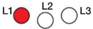
text_image
Diagram showing connection between a medical device and an OCT-OP monitor with labeled ports and control buttons
natural_image
Diagram of a medical or electrical testing setup with a device connected to an oscilloscope via red and green wires (no text or labels visible)natural_image
Diagram of a connected electrical device with two connected devices (no text or symbols)Thank you for purchasing this CA 6651 electric vehicle charging station tester.
For best results from your instrument:
■ read these operating instructions carefully,
■ comply with the precautions for use.

WARNING, risk of DANGER! The operator must refer to these instructions whenever this danger symbol appears.

Equipment protected by double insulation.

Information or useful tip.

The product is declared recyclable following an analysis of the life cycle in accordance with standard ISO 14040.

The CE marking indicates compliance with the European Low Voltage Directive, 2014/35/UE, the Electromagnetic Compatibility Directive, 2014/30/EU, and the Restriction of Hazardous Substances Directive, (RoHS 2011/65/UE and 2015/863/UE).

The UKCA marking certifies that the product is compliant with the requirements that apply in the United Kingdom, in particular as regards Low-Voltage Safety, Electromagnetic Compatibility, and the Restriction of Hazardous Substances.
The rubbish bin with a line through it indicates that, in the European Union, the product must undergo selective disposal in compliance with Directive WEEE 2012/19/EU.
Definition of measurement categories
■ Measurement category IV corresponds to measurements taken at the source of low-voltage installations. Example: power feeders, counters and protection devices.
■ Measurement category III corresponds to measurements on building installations. Example: distribution panel, circuit-breakers, machines or fixed industrial devices.
■ Measurement category II corresponds to measurements taken on circuits directly connected to low-voltage installations.
Example: power supply to electro-domestic devices and portable tools.
PRECAUTIONS FOR USE
This instrument is compliant with safety standards IEC/EN 61010-2-030 or BS EN 61010-2-030 and the leads are compliant with IEC/EN 61010-2-031 or BS EN 61010-2-031, for voltages up to 300 V in category II.
Failure to observe the safety instructions may result in electric shock, fire, explosion, and destruction of the instrument and of the installations.
■ The operator and/or the responsible authority must carefully read and clearly understand the various precautions to be taken in use. Sound knowledge and a keen awareness of electrical hazards are essential when using this instrument.
If you use this instrument other than as specified, the protection it provides may be compromised, thereby endangering you.
■ The tests can be performed only by an EVCI-qualified electrician or under the supervision of a qualified electrician. The qualified individual must be trained for the specific task.
■ Do not use the instrument on networks of which the voltage or category exceeds those mentioned. The CA 6651 can be used only on 230VAC/400VAC charging stations.
■ Do not use the instrument if it seems to be damaged, incomplete, or poorly closed.
■ Before each use, check that the insulation on the cord, connector, and housing is in good condition. Any item of which the insulation is deteriorated (even partially) must be set aside for repair or scrapping.
■ All troubleshooting and metrological checks must be done by competent, accredited personnel.
CONTENTS
1. PRESENTATION ......21
1.1. Delivery condition .....21
1.2. Introduction ......21
1.3. Presentation ......22
1.4. Side view ......23
2. USE....24
2.1. Visual inspection .....24
2.2. Functional test .....25
2.3. Fault simulation .....26
2.4. Check of electrical safety .....27
2.5. Test of operation of the charging terminal ....30
2.6. Test report ....32
3. TECHNICAL CHARACTERISTICS .....33
3.1. Reference conditions ....33
3.2. Electrical characteristics .....33
3.3. Power supply ....33
3.4. Environmental conditions .....33
3.5. Construction characteristics .....33
3.6. Compliance with international standards ....34
3.7. Electromagnetic compatibility (CEM) .. 34
4. MAINTENANCE......35
4.1. Cleaning 35
4.2. Replacing the fuse ....35
5. WARRANTY....35
1.1. DELIVERY CONDITION
The CA 6651 is delivered in a cardboard box containing:
■ One carrying case
■ One cable terminated by a type 2 connector
■ Operating instructions in 5 languages
For the accessories and spares, consult our web site: www.chauvin-arnoux.com
1.2. INTRODUCTION
Charging stations for electric cars must be tested after installation, then tested periodically when in service.
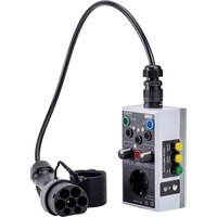
The CA 6651 electric vehicle charging station tester is used to:
■ Check the connections of the protective conductor (charging terminal side and vehicle side).
■ Simulate the connection of an electric vehicle to the charging station being tested.
Different charging levels can be simulated (NC, 13A, 20A, 32A and 63A) along with different electric vehicle charging modes (A, B, C, D)
■ Simulate a fault (short circuit between CP and PE, short circuit by diode between CP and PE, open PE).
■ Access the different points of the type 2 connector (L1, L2, L3, N, PE) and use them to perform tests.
With a multifunction tester connected to the CA 6651, you can:
■ Make earth measurements,
■ Perform RCD (differential) tests,
■ Make insulation measurements,
■ Make continuity measurements.
With an oscilloscope connected to the CA 6651, you can also observe the pilot signal.
The CA 6651 is powered by the charging station it is testing.
The CA 6651 is intended for use in charging mode 3 with a type 2 connector. This means that the charging is controlled by the terminal.

The CA 6651 does not allow the charging of electric vehicles.
The operation of the CA 6651 satisfies the requirements of the following standards:
■ IEC 61851-1: Electric vehicle conductive charging system - Part 1: General requirements,
■ IEC 60364-7-722: Requirements for special installations or locations - Supplies for electric vehicles.
1.3. PRESENTATION
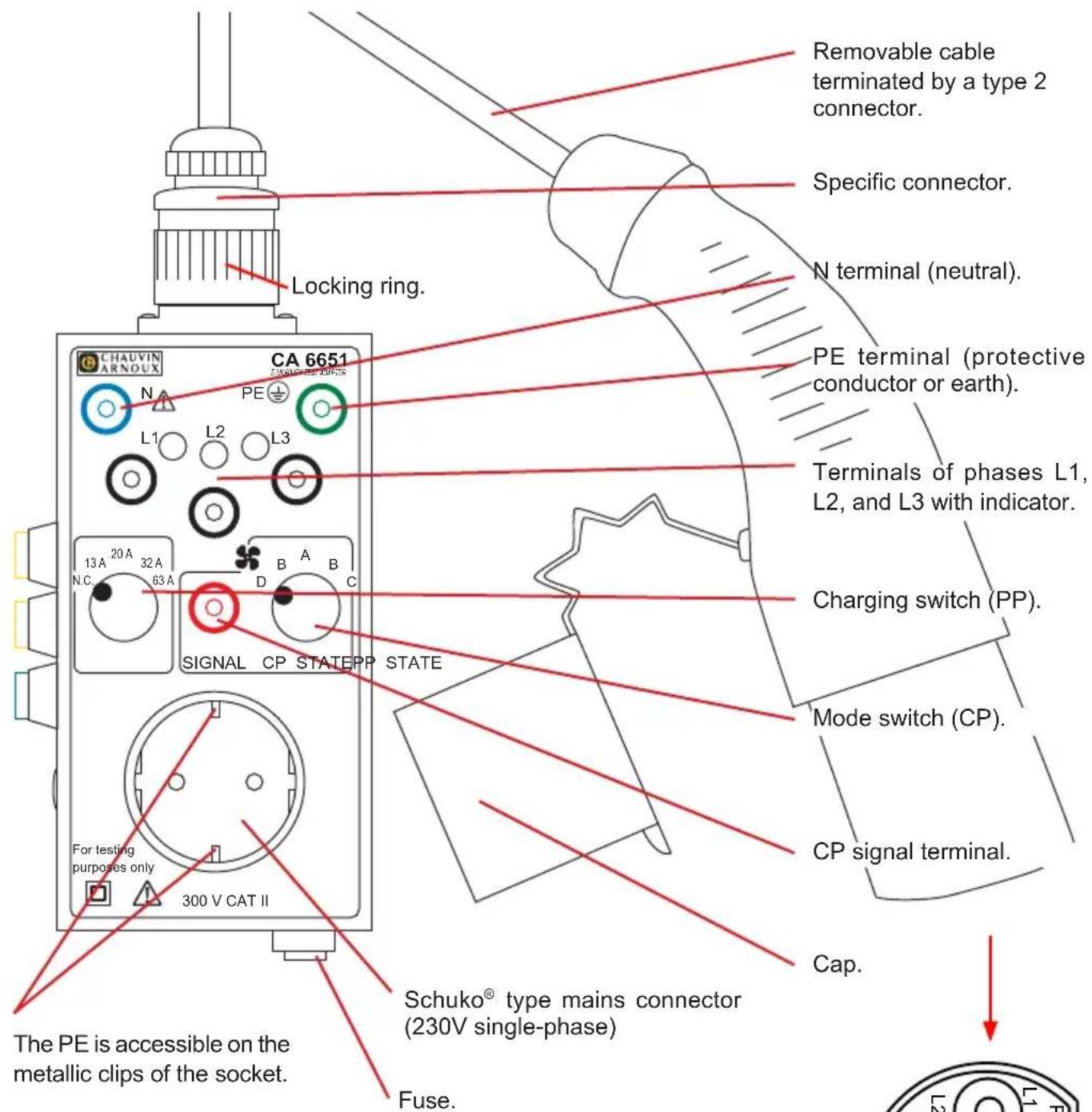
text_image
CHAUVIN ARNOUX CA 6651 N L1 L2 L3 Locking ring. 13 A 20 A 32 A N.C. 63 A SIGNAL CP STATEPP STATE For testing purposes only 300 V CAT II The PE is accessible on the metallic clips of the socket. Schuko® type mains connector (230V single-phase) Fuse. Removable cable terminated by a type 2 connector. Specific connector. N terminal (neutral). PE terminal (protective conductor or earth). Terminals of phases L1, L2, and L3 with indicator. Charging switch (PP). Mode switch (CP). CP signal terminal. Cap. The PE is accessible on the metallic clips of the socket.Type 2 connector.
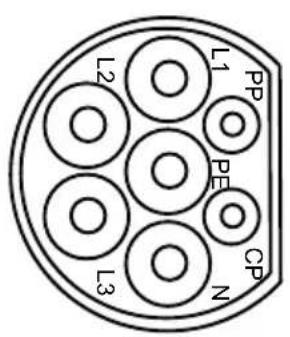
text_image
L1 L2 PP PE CP N L31.4. SIDE VIEW
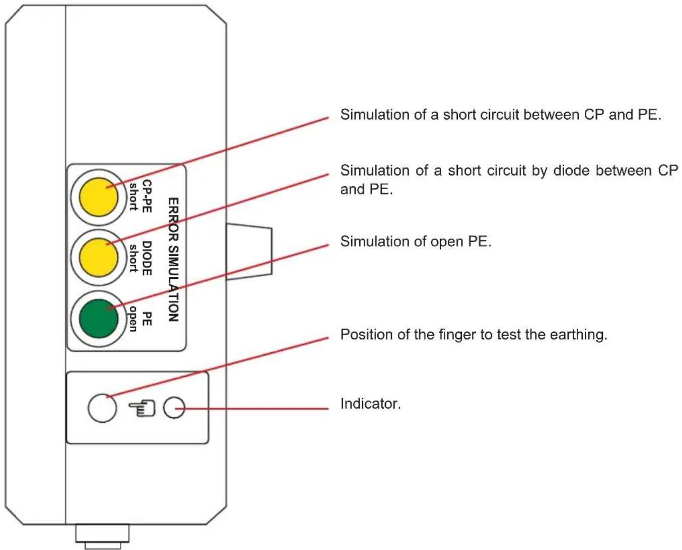
text_image
Simulation of a short circuit between CP and PE. Simulation of a short circuit by diode between CP and PE. Simulation of open PE. Position of the finger to test the earthing. Indicator.
The tests can be performed only by or under the supervision of an EVCI-qualified electrician.
In France, decree no. 2017-26 of 12/01/2017 concerning charging infrastructure for electric vehicles imposes stringent requirements.
The EVCI-qualified electrician must observe the rules and standards required for their work, and is not allowed to skip steps needed to ensure the correct and safe use of the charging station.
They must then document the tests in a test report, whether the tests are complete or not.
2.1. VISUAL INSPECTION
The test of the electric vehicle charging station must begin with a visual inspection of the station itself and also of the testing instrument.
2.1.1. INSPECTION OF THE CHARGING STATION
Check that it is installed in a suitable place.
Look for:
■ damage to the structure,
■ damage to the power cord,
■ signs of overloading or improper use,
■ inappropriate alterations,
■ missing protective covers,
■ dirt or corrosion that might impair safety.
Check:
■ the presence of the required fans,
■ the type 2 connector,
■ tightness,
■ the legibility of the texts,
■ on the screen, that the supply voltage of the charging station is between 230 and 400 VAC.

Visible damage that might interfere, mechanically or electrically, with the safe use of the station, or that might cause a fire, must be repaired immediately.
2.1.2. INSPECTION OF THE INSTRUMENT
Check that the environmental conditions are compatible with correct use.
Check:
■ the condition of the instrument (not damaged, incomplete, or incorrectly closed),
■ the condition of the insulation on the leads, connector, and housing.
■ the connections: the terminals, the cable, the connectors, the socket,
■ the markings on the tester and the connecting cable (300V CAT II).
2.2. FUNCTIONAL TEST
The functional test consists in verifying that the protective conductor (PE) is correctly earthed and that its voltage with respect to earth is zero.
■ Connect the cord with the type 2 connector to the CA 6651. Screw on the locking ring.
■ Connect the type 2 connector to the charging terminal of the electric vehicle.
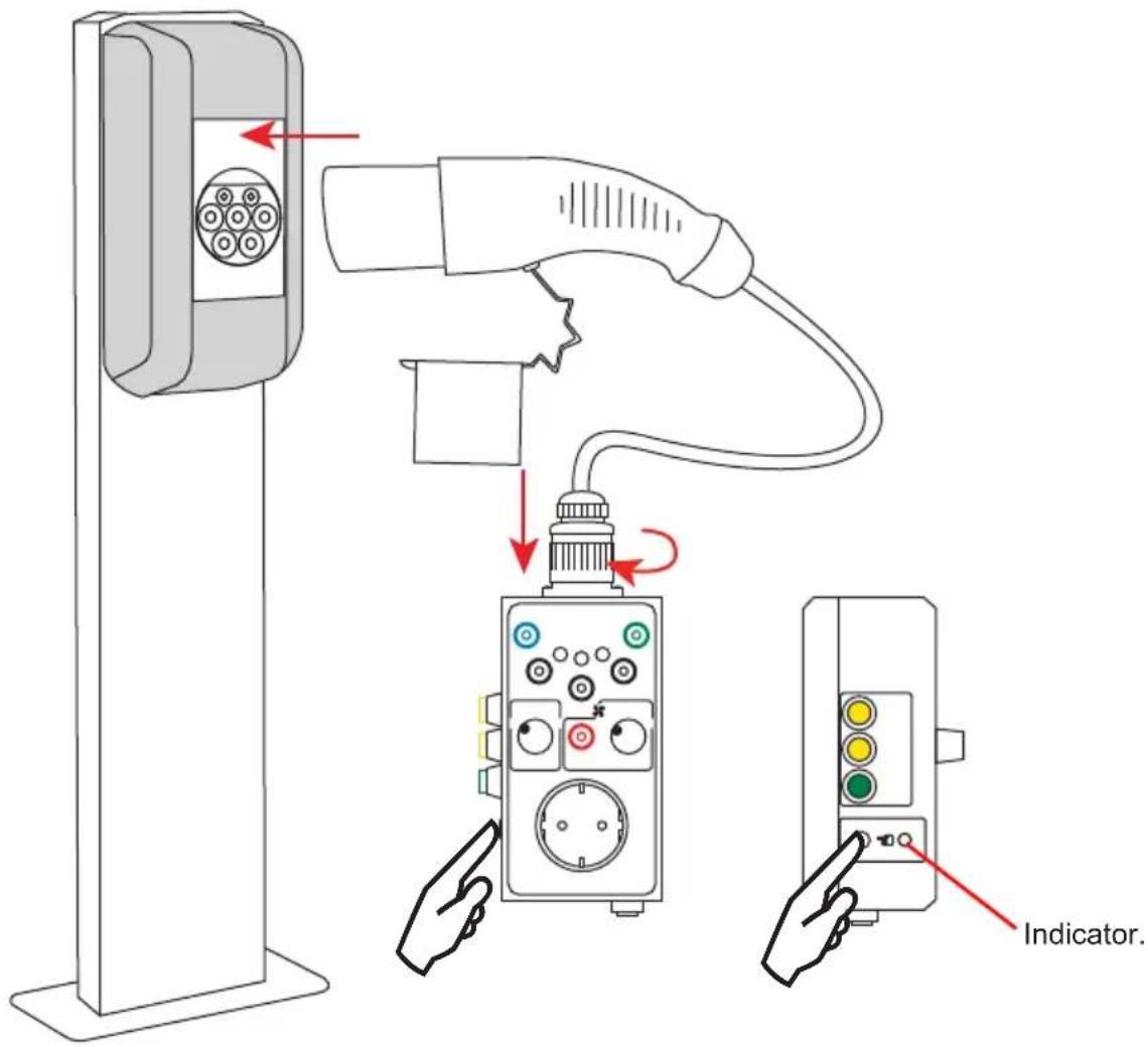
text_image
Indicator.■ Place your bare finger on the side of the housing, at the specialized location.

Once the instrument is connected, do not touch the connector until the PE has been tested: the accessible metallic part of the connector may be at a hazardous voltage.
If the voltage of the PE with respect to earth is not zero, the indicator lights. The tests must then be stopped and the terminal must be repaired.
2.3. FAULT SIMULATION
Once the functional test has been carried out successfully, perform a fault simulation
2.3.1. SHORT CIRCUIT BETWEEN CP AND PE
Pressing the CP-PE short button simulates a short circuit between the CP signal and the PE protection conductor for 3 seconds.
The charging station must lock for 30 seconds. The terminal indicates that it is locked. The charging process underway is stopped. After 30 seconds, the terminal reports that there is no more fault and unlocks.
This test must be conducted on each charging mode: A, B, C and D.
2.3.2. SHORT CIRCUIT BY DIODE BETWEEN CP AND PE
Pressing the DIODE short button simulates a short circuit by diode between the CP signal and the PE protection conductor. This fault duration is the same as the length of the button press.
The charging terminal must deactivate within 30 seconds. The terminal indicates that it is locked. The charging process underway is stopped. After 30 seconds, the terminal reports that there is no more fault and unlocks.
This test must be conducted on each charging mode: A, B, C and D
2.3.3. PE OPEN
Pressing the PE open button simulates disconnection of the PE protection conductor.
The charging terminal must deactivate within 100 ms. The terminal is locked and only an EVCI approved installer can reactivate it.

If any of these 3 faults fails to lock the terminal, the tests must be stopped and the terminal must be repaired.
2.4. CHECK OF ELECTRICAL SAFETY
To check the electrical safety of the charging terminal of an electric vehicle, you must have a multifunction tester (for example CA 6117, CA 6131, CA 6133 or MX535).
2.4.1. TEST OF MAINS POWER
This test serves to check that the charging terminal is correctly supplied.
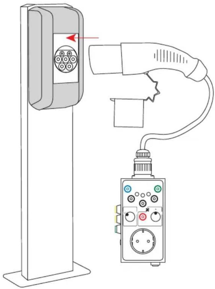
■ Connect the cord with the type 2 connector to the CA 6651.
■ Set the charging switch (PP) to N.C. and the mode switch (CP) to C or D.
■ Connect the type 2 connector to the charging terminal of the electric vehicle.
natural_image
Line drawing of a charging station connected to an electrical outlet (no text or symbols)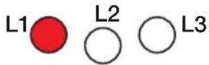
If the charging terminal is supplied at 230V single-phase, only one of the three indicators, L1, L2, or L3, lights.
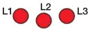
If the charging terminal is supplied at 400V three-phase, all three indicators light.
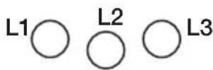
If the neutral conductor, N, is not connected, the indicators do not light.
Correct the fault in order to be able to continue the tests.

Indicators L1, L2, and L3 cannot be used to determine the phase order.
If the conductors are correctly connected, you can continue the electrical safety tests.

If there is no power to the CA 6651, check the fuse (see § 4.2).
2.4.2. CHECK OF THE EARTH
This measurement serves to check the connection of the charging terminal to earth.
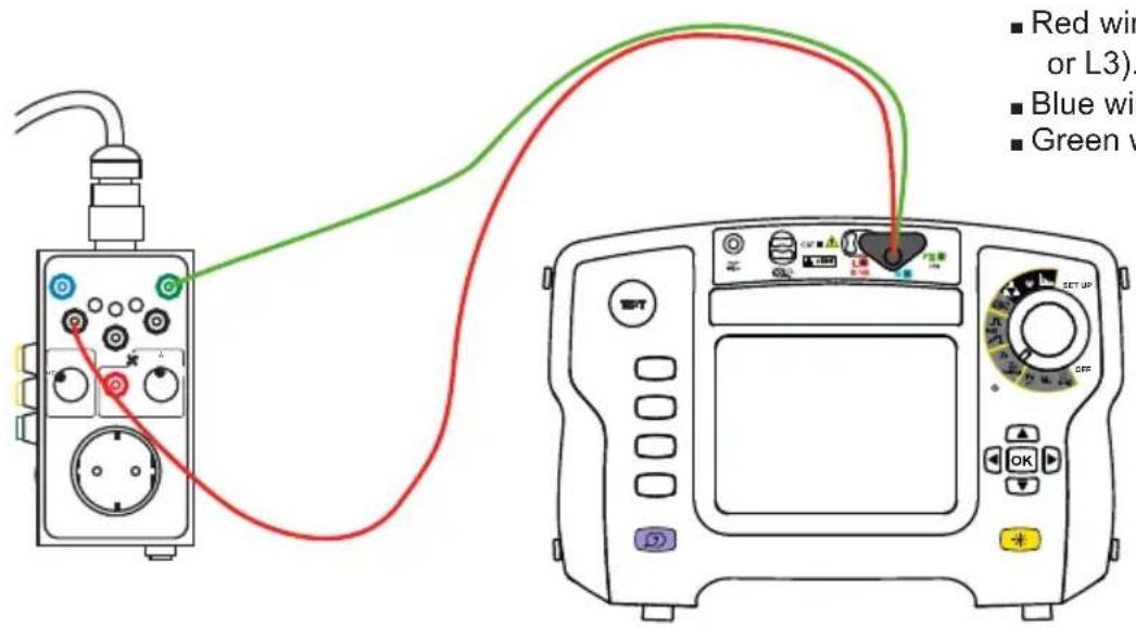
■ Set the charging switch (PP) to N.C. and the mode switch (CP) to A (earth measurement with no voltage) or on C or D (measurement of loop impedance with voltage).
■ Connect the installation tester to the CA 6651. Via the Schuko® type connector (2P+E), for single-phase (L1, N, and PE terminals)

text_image
Diagram showing a medical device connected to an oscilloscope with labeled ports and a red arrow indicating the cable connection.
Do not use the Schuko ^® type connector for anything other than the test. Do not connect an electrical load to it.
Or via the L1, L2, L3, and N or PE terminals, for three-phase or if the installation tester does not have a cord with a mains plug.
text_image
■ Red wire or L3). ■ Blue wire. ■ Green w■ Make a loop measurement without tripping. For this, refer to the operating instructions of the multifunction tester.
The loop impedance must be less than 100 (per the NFC 15100 or IEC 60364 standard).
2.4.3. CHECK OF THE PROTECTIVE CIRCUIT-BREAKER
After checking the connection to earth, check the operation of the differential circuit-breaker (RCD: Residual Current Device).
■ Connect the multifunction tester in the same way as for an earth measurement.
■ Perform an RCD ramp test. For this, refer to the operating instructions of the multifunction tester.
In the case of a three-phase network, reset the RCD and repeat the test with the wire red connected to phase L2. Then repeat with phase L3.
At the end of the test, leave the RCD open in order to perform the no-voltage insulation test.
2.4.4. INSULATION MEASUREMENT
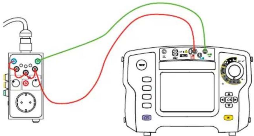
This test must be performed with no voltage. None of the indicators of the CA 6651 must be lit.
■ Connect the L1, L2, L3, and N terminals together and make an insulation measurement with respect to the PE. For this, refer to the operating instructions of the multifunction tester.
text_image
Diagram showing connections between a device with labeled components and an analog oscilloscope interface.The insulation resistance must be greater than 500kΩ for a 230V single-phase network and greater than 1MΩ for a 400V three-phase network.
2.4.5. CONTINUITY MEASUREMENT
This test must be performed with no voltage. None of the indicators of the CA 6651 must be lit.
■ Connect the PE terminal and the earth of the installation that supplies the charging terminal to the multifunction tester and make a continuity measurement.
Refer to the operating instructions of the multifunction tester.

Do not forget to reset the RCD at the end of the test.
Before starting this test, redo a functional test (check of the PE).
2.5.1. SIMULATION OF A VEHICLE
■ Set the charging switch (PP) to N.C.
■ The voltages and resistances given below are for guidance.
| Mode switch (CP) | Simulated vehicle | |
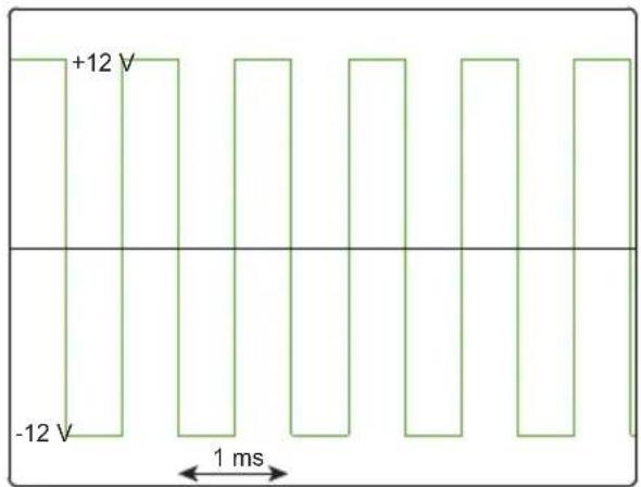
| A Vehicle | disconnected | The charging terminal delivers no energy.■ CP-PE voltage: ±12V at 1kHz■ CP-PE resistance: infinite |
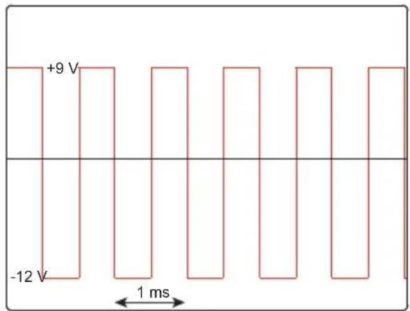
| B Vehicle | connected | The charging terminal delivers no energy.■ CP-PE voltage: +9V/-12V at 1kHz■ CP-PE resistance: 2,740Ω |
| C | Vehicle charging without ventilation | The charging terminal delivers energy.■ CP-PE voltage: +6V/-12V at 1kHz■ CP-PE resistance: 1,300Ω |
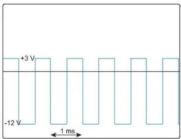
| D | Vehicle charging with ventilation of the terminal. | The charging terminal delivers energy.■ CP-PE voltage: +3V/-12V at 1kHz■ CP-PE resistance: 270Ω |
To simulate charging without ventilation, execute the sequence A, B, C.
To simulate charging with ventilation of the charging terminal, execute the sequence A, B, D.
■ Set the mode switch (CP) to C or D
| Charging switch (PP) PP-PE resistance | |
| N.C. infinite | |
| 13A 1,500kΩ | |
| 20A 680Ω | |
| 32A 220Ω | |
| 63A 100Ω | |
2.5.2. CHECK OF THE SIGNAL
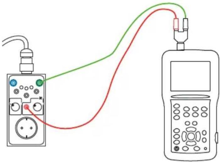
To check the signal, you must have a Handscope type oscilloscope.
■ Connect the oscilloscope between the SIGNAL and PE terminals.
text_image
Diagram showing two connected devices with labeled ports and colored wires (red, green, blue) connecting them.The signals when the charging switch (PP) is set to N.C. take the following forms:
other
| Time (ms) | Voltage (V) | | --------- | ----------- | | 0 | +12 | | 1 | -12 | | 2 | +12 | | 3 | -12 | | 4 | +12 | | 5 | -12 | | 6 | +12 | | 7 | -12 | | 8 | +12 | | 9 | -12 | | 10 | +12 | | 11 | -12 | | 12 | +12 | | 13 | -12 | | 14 | +12 | | 15 | -12 | | 16 | +12 | | 17 | -12 | | 18 | +12 | | 19 | -12 | | 20 | +12 | | 21 | -12 | | 22 | +12 | | 23 | -12 | | 24 | +12 | | 25 | -12 | | 26 | +12 | | 27 | -12 | | 28 | +12 | | 29 | -12 | | 30 | +12 | | 31 | -12 | | 32 | +12 | | 33 | -12 | | 34 | +12 | | 35 | -12 | | 36 | +12 | | 37 | -12 | | 38 | +12 | | 39 | -12 | | 40 | +12 | | 41 | -12 | | 42 | +12 | | 43 | -12 | | 44 | +12 | | 45 | -12 | | 46 | +12 | | 47 | -12 | | 48 | +12 | | 49 | -12 | | 50 | +12 | | 51 | -12 | | 52 | +12 | | 53 | -12 | | 54 | +12 | | 55 | -12 | | 56 | +12 | | 57 | -12 | | 58 | +12 | | 59 | -12 | | 60 | +12 | | 61 | -12 | | 62 | +12 | | 63 | -12 | | 64 | +12 | | 65 | -12 | | 66 | +12 | | 67 | -12 | | 68 | +12 | | 69 | -12 | | 70 | +12 | | 71 | -12 | | 72 | +12 | | 73 | -12 | | 74 | +12 | | 75 | -12 | | 76 | +12 | | 77 | -12 | | 78 | +12 | | 79 | -12 | | 80 | +12 | | 81 | -12 | | 82 | +12 | | 83 | -12 | | 84 | +12 | | 85 | -12 | | 86 | +12 | | 87 | -12 | | 88 | +12 | | 89 | -12 | | 90 | +12 | | 91 | -12 | | 92 | +12 | | 93 | -12 | | 94 | +12 | | 95 | -12 | | 96 | +12 | | 97 | -12 | | 98 | +12 | | 99 | -12 | | 100 | +12 |CP switch set to A. CP switch set to B.
other
| Time (ms) | Voltage (V) | | --------- | ----------- | | 0 | +9 | | 1 | -12 | | 2 | +9 | | 3 | -12 | | 4 | +9 | | 5 | -12 | | 6 | +9 | | 7 | -12 | | 8 | +9 | | 9 | -12 | | 10 | +9 | | 11 | -12 | | 12 | +9 | | 13 | -12 | | 14 | +9 | | 15 | -12 | | 16 | +9 | | 17 | -12 | | 18 | +9 | | 19 | -12 | | 20 | +9 | | 21 | -12 | | 22 | +9 | | 23 | -12 | | 24 | +9 | | 25 | -12 | | 26 | +9 | | 27 | -12 | | 28 | +9 | | 29 | -12 | | 30 | +9 | | 31 | -12 | | 32 | +9 | | 33 | -12 | | 34 | +9 | | 35 | -12 | | 36 | +9 | | 37 | -12 | | 38 | +9 | | 39 | -12 | | 40 | +9 | | 41 | -12 | | 42 | +9 | | 43 | -12 | | 44 | +9 | | 45 | -12 | | 46 | +9 | | 47 | -12 | | 48 | +9 | | 49 | -12 | | 50 | +9 | | 51 | -12 | | 52 | +9 | | 53 | -12 | | 54 | +9 | | 55 | -12 | | 56 | +9 | | 57 | -12 | | 58 | +9 | | 59 | -12 | | 60 | +9 | | 61 | -12 | | 62 | +9 | | 63 | -12 | | 64 | +9 | | 65 | -12 | | 66 | +9 | | 67 | -12 | | 68 | +9 | | 69 | -12 | | 70 | +9 | | 71 | -12 | | 72 | +9 | | 73 | -12 | | 74 | +9 | | 75 | -12 | | 76 | +9 | | 77 | -12 | | 78 | +9 | | 79 | -12 | | 80 | +9 | | 81 | -12 | | 82 | +9 | | 83 | -12 | | 84 | +9 | | 85 | -12 | | 86 | +9 | | 87 | -12 | | 88 | +9 | | 89 | -12 | | 90 | +9 | | 91 | -12 | | 92 | +9 | | 93 | -12 | | 94 | +9 | | 95 | -12 | | 96 | +9 | | 97 | -12 | | 98 | +9 | | 99 | -12 | | 100 | +9 |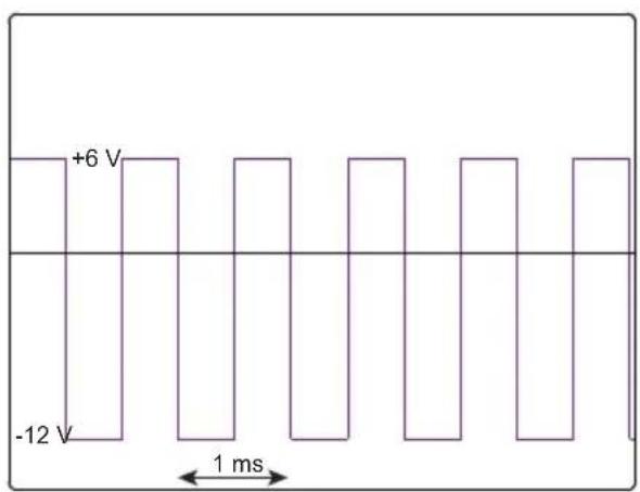
other
| Voltage Level | Time Scale | | ------------- | ---------- | | +6 V | 0 | | -12 V | 1 ms |CP switch set to C.
other
| Time (ms) | Voltage (V) | | --------- | ----------- | | 0 | +3 | | 1 | -12 | | 2 | +3 | | 3 | -12 | | 4 | +3 | | 5 | -12 | | 6 | +3 | | 7 | -12 | | 8 | +3 | | 9 | -12 | | 10 | +3 | | 11 | -12 | | 12 | +3 | | 13 | -12 | | 14 | +3 | | 15 | -12 | | 16 | +3 | | 17 | -12 | | 18 | +3 | | 19 | -12 | | 20 | +3 | | 21 | -12 | | 22 | +3 | | 23 | -12 | | 24 | +3 | | 25 | -12 | | 26 | +3 | | 27 | -12 | | 28 | +3 | | 29 | -12 | | 30 | +3 | | 31 | -12 | | 32 | +3 | | 33 | -12 | | 34 | +3 | | 35 | -12 | | 36 | +3 | | 37 | -12 | | 38 | +3 | | 39 | -12 | | 40 | +3 | | 41 | -12 | | 42 | +3 | | 43 | -12 | | 44 | +3 | | 45 | -12 | | 46 | +3 | | 47 | -12 | | 48 | +3 | | 49 | -12 | | 50 | +3 | | 51 | -12 | | 52 | +3 | | 53 | -12 | | 54 | +3 | | 55 | -12 | | 56 | +3 | | 57 | -12 | | 58 | +3 | | 59 | -12 | | 60 | +3 | | 61 | -12 | | 62 | +3 | | 63 | -12 | | 64 | +3 | | 65 | -12 | | 66 | +3 | | 67 | -12 | | 68 | +3 | | 69 | -12 | | 70 | +3 | | 71 | -12 | | 72 | +3 | | 73 | -12 | | 74 | +3 | | 75 | -12 | | 76 | +3 | | 77 | -12 | | 78 | +3 | | 79 | -12 | | 80 | +3 | | 81 | -12 | | 82 | +3 | | 83 | -12 | | 84 | +3 | | 85 | -12 | | 86 | +3 | | 87 | -12 | | 88 | +3 | | 89 | -12 | | 90 | +3 | | 91 | -12 | | 92 | +3 | | 93 | -12 | | 94 | +3 | | 95 | -12 | | 96 | +3 | | 97 | -12 | | 98 | +3 | | 99 | -12 | | 100 | +3 |CP switch set to D

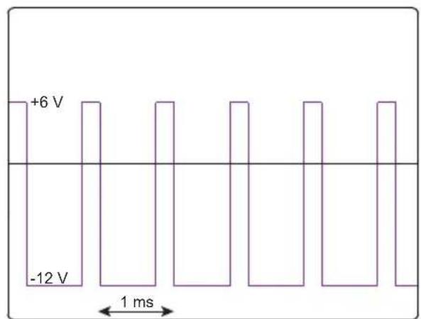
When the mode switch (CP) is set to C or D and the charging switch is not set to N.C., the signal uses pulse width modulation (PWM) to indicate the available charging current (13A, 20A, 32A or 63A).
The signals then take the following forms:
other
| Voltage Level | Time to 1 ms | | ------------- | ------------ | | +6 V | 0 | | -12 V | 0 | | 0 | 0 | | +6 V | 1 ms | | -12 V | 1 ms |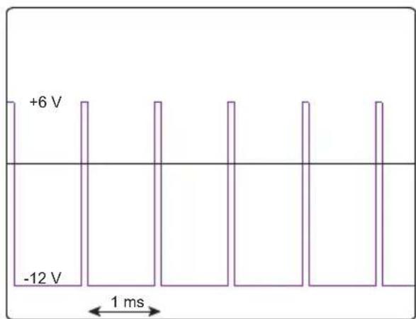
line
| Voltage | Time (ms) | | ------- | --------- | | +6 V | 0 | | -12 V | 0 |For more details of the communication protocol, please refer to standard IEC 61851-1 and the documentation from the manufacturer of the charging station.
2.6. TEST REPORT
The tests must be documented.
If a terminal is hazardous, this must be clearly indicated on the terminal, and the organization responsible for the terminal and the supplier of electricity must be so informed in writing.
The test report must contain:
■ a list of the items inspected visually,
■ the results of each measurement and each test,
■ any changes made to the charging terminal.
The terminal must bear a label indicating: Tested per standards XXX.
A test report compliant with this standard will soon be available for the CA 6116N and CA 6117 via the DataView® application software.
3.1. REFERENCE CONDITIONS
| Quantity of influence Reference values | |
| Temperature 23±5°C | |
| Relative Humidity 20 to 75%RH | |
| Supply voltage | 230 V single-phase400 V three-phase |
| Frequency of the measured signal 50Hz |
3.2. ELECTRICAL CHARACTERISTICS
Maximum current: 13 AAc (no DC)
Max. charging power: 2,3 kVA
Maximum current in the mains connector: 10 A for 10 seconds.
The mains connector is protected against overloads by a fuse.
Type 2 connector: 32A, 3PH+N+PE, type E-2201, 200/346V-240/415V
3.3. POWER SUPPLY
The CA 6651 is supplied by the charging terminal being tested via the type 2 connector.
3.4. ENVIRONMENTAL CONDITIONS
For indoor use, outdoor use without rain.
Domain of use -10 to 45°C, 80% RH without condensation
Storage -25 to 60°C, 80%RH without condensation
Pollution degree 2.
Altitude <2,000m.
3.5. CONSTRUCTION CHARACTERISTICS
Dimensions of the housing (L x W x H) 150 x 83 x 77mm
Dimensions of the type 2 connector 208 x 58 x 51mm
Length of the cable approximately 53cm
Weight approximately 830g
Protection index IP20 per IEC 60529.
3.6. COMPLIANCE WITH INTERNATIONAL STANDARDS
The instrument is compliant with standards IEC/EN 61010-2-030 or BS EN 61010-2-030 and the leads are compliant with IEC/EN 61010-2-031 or BS EN 61010-2-031: 300V Category II, degree of pollution 2.
Instrument with double insulation
3.7. ELECTROMAGNETIC COMPATIBILITY (CEM)
Emission and immunity in an industrial environment per IEC/EN 61326-1 or BS EN 61326-1.
4. MAINTENANCE

The instrument has no parts that can be replaceable by personnel who are not trained and approved. Any unauthorized repair or replacement of a part by an “equivalent” may gravely impair safety.
4.1. CLEANING
Disconnect the unit completely.
Use a soft cloth, dampened with soapy water. Rinse with a damp cloth and dry rapidly with a dry cloth or forced air. Do not use alcohol, solvents, or hydrocarbons.
4.2. REPLACING THE FUSE
To guarantee continuity of safety, replace the defective fuse only with a fuse with strictly identical characteristics: T - 10A - 250V - 5 x 20 mm.
■ Disconnect all connections from the device.
■ Using a flat screwdriver, unscrew the fuse holder.
■ Remove the defective fuse and replace it with the new fuse.
■ Replace the fuse holder in its housing and screw it back in.
5. WARRANTY
Except as otherwise stated, our warranty is valid for 24 months starting from the date on which the equipment was sold. Extract from our General Conditions of Sale provided on request.
www.group.chauvin-arnoux.com/en/general-terms-of-sale
The warranty does not apply in the following cases :
■ Inappropriate use of the equipment or use with incompatible equipment;
■ Modifications made to the equipment without the explicit permission of the manufacturer's technical staff;
■ Work done on the device by a person not approved by the manufacturer;
■ Adaptation to a particular application not anticipated in the definition of the equipment or not indicated in the user's manual;
■ Damage caused by shocks, falls, or floods.
text_image
Diagram illustrating the installation of an electric vehicle charging station connected to a device via LED, with labeled components and directional arrows.natural_image
Diagram of a charging station connected to an electrical outlet, showing wiring and control buttons (no text or symbols present)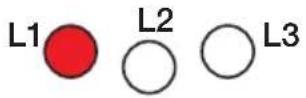
text_image
Diagram showing a medical device connected to an oscilloscope with labeled ports and a red arrow indicating connection point.
text_image
Diagram showing connections between a multimeter and an analog oscilloscope with labeled ports and wiring pathsnatural_image
Diagram of a connected electrical device with two connected components (no text or symbols)text_image
Diagram illustrating the installation of an electric vehicle charging station, showing cable routing and control panel assembly with labeled 'Spia.' component.natural_image
Diagram of a charging station connected to an electrical plug, showing wiring and control panel (no text or symbols)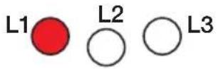
text_image
Diagram showing a medical device connected to an OCT-OP monitor with labeled ports and a red arrow indicating connection point.
natural_image
Diagram of a medical or electrical testing setup with a device connected to an oscilloscope via red and green wires (no text or labels visible)text_image
Diagram showing two connected devices with labeled ports and wiring, illustrating a signal or measurement setup.other
| Voltage Level | Time Segment | | ------------- | ------------ | | +9 V | 0 to +9 ms | | -12 V | 0 to +9 ms |natural_image
Diagram of a charging station connected to an electrical plug, showing wiring and control panel (no text or symbols)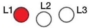
text_image
Diagram showing connection between a medical device and an OCT-OP device with labeled ports and wiring
text_image
Diagram showing connections between a device with colored wires and labeled ports, likely illustrating an electrical or diagnostic setup.text_image
Diagram showing two connected devices with labeled ports and colored wires (red, green, blue) connecting them.other
| Voltage Level | Time Segment | | ------------- | ------------ | | +9 V | 0 to +9 ms | | -12 V | 0 to +9 ms |natural_image
Two icons: a folded document and a recycling bin with an arrow (no text or symbols)FRANCE
Chauvin Arnoux
12-16 rue Sarah Bernhardt
92600 Asnières-sur-Seine
Our international contacts
www.chauvin-arnoux.com/contacts

CHAUVIN
ARNOUX