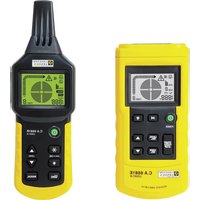
C.A 6681 - Electrical tester CHAUVIN ARNOUX - Free user manual and instructions
Find the device manual for free C.A 6681 CHAUVIN ARNOUX in PDF.


User questions about C.A 6681 CHAUVIN ARNOUX
0 question about this device. Answer the ones you know or ask your own.
Ask a new question about this device
Download the instructions for your Electrical tester in PDF format for free! Find your manual C.A 6681 - CHAUVIN ARNOUX and take your electronic device back in hand. On this page are published all the documents necessary for the use of your device. C.A 6681 by CHAUVIN ARNOUX.
USER MANUAL C.A 6681 CHAUVIN ARNOUX
3.2 APPLICATION UNIPOLAIRE....14
3.2.1 LOCALISATION ET SUIVI DE LIGNES ET DE PRISES....14
3.2.2 LOCALISATION DES INTERRUPTIONS DE LIGNES....15
3.2.3 LOCALISATION D'INTERRUPTIONS DE LIGNE À L'AIDE DE DEUX ÉMETTEURS ....16
3.2.4 DÉTECTION DE DÉFAUTS D'UN SYSTÈME DE CHAUFFAGE PAR LE SOL....18
3.2.5 DÉTECTION DE LA PARTIE RÉTRÉCIE (BOUCHÉE) D'UN TUYAU NON MÉTALLIQUE....19
3.2.6 DÉTECTION D'UN TUYAU MÉTALLIQUE D'ADDUCTION D'EAU ET DE CHAUFFAGE....20
3.2.7 IDENTIFICATION DE CIRCUIT D'ALIMENTATION SUR UN MÊME ÉTAGE....21
3.2.8 SUIVI D'UN CIRCUIT ENFOUI....22
3.3 APPLICATIONS BIPOLAIRES ......23
3.3.1 APPLICATIONS EN CIRCUITS FERMÉS....23
3.3.2 RECHERCHE DE FUSIBLES 24
3.3.3 RECHERCHE D'UN COURT-CIRCUIT 25
3.3.4 DÉTECTION DE CIRCUITS ENFOUIS RELATIVEMENT PROFONDÉMENT....26
3.3.5 TRI OU DÉTERMINATION DE CONDUCTEURS PAR PAIRE....27
Français
3.4 MÉTHODE D'AUGMENTATION DU RAYON EFFECTIF DE DÉTECTION DES CIRCUITS SOUS TENSION....28
3.5 IDENTIFICATION DE LA TENSION DU RÉSEAU ET RECHERCHE DE COUPURES DANS LE CIRCUIT....29
4. AUTRES FONCTIONS ......30
4.1 FONCTION DE VOLTMÈTRE DE L'ÉMETTEUR....30
4.2 FONCTION LAMPE TORCHE ....30
4.3 FONCTION DE RÉTRO-ÉCLAIRAGE....30
4.4 ACTIVATION / DÉSACTIVATION DU BUZZER....30
natural_image
Line drawing of a handheld device connected to a wire with three circular motion arrows indicating clockwise motion (no text or symbols)Fig.1
2. DESCRIPTION
2.1 ÉMETTEUR
2.1.1 DESCRIPTION GLOBALE
text_image
11 10 1 LEVEL CODE 8 ~1888v CODE 8 2 POWER 3 START STOP LEVEL SEL. ▲ CODE SEL. 4 5 9 8 7 6 IEC61010-1 500V CATIII + 500V AC~Fig.2
text_image
Diagram of a digital testing device with labeled parts including control panel, level display, and function buttonsFig.4
text_image
LEVEL AUTO signal 1888 CODE 8 Fig.6text_image
LEVEL MANUAL signal 1888 CODE 8 Fig.7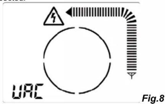
text_image
URC Fig.82.2.4 REMARQUES CONCERNANT LE FONCTIONNEMENT DES TOUCHES
natural_image
Diagram of three mobile phones connected to a cable with a magnified inset showing a device (no text or symbols present)Fig.9
text_image
Diagram showing three connected devices with warning symbols and grounding, likely illustrating a safety or electrical hazard detection setup.Fig.10
Remarque :
natural_image
Line drawing of three handheld devices connected to a cable with wiring, showing signal propagation (no text or symbols)Fig.11
Remarques :
text_image
Diagram of a circuit setup with labeled devices F and C connected to wires, showing connections via wires and a magnified inset of a cable or connector.Fig.12
Remarques :
natural_image
Diagram showing three devices connected to a grid-like structure with a circular arrow indicating rotation (no text or symbols present)Fig.13a
text_image
Diagram showing three devices labeled F, C, and C connected to a grid with a circular arrow indicating rotation or signal flow.Fig.13b
natural_image
Line drawing of three handheld devices connected to a wall-mounted device, with no visible text or symbols.Fig.14
Remarques :
natural_image
Diagram of electrical measurement setup with devices and cables (no text or labels)Fig.15a
natural_image
Illustration of four handheld devices connected to a wall-mounted grid device (no text or symbols visible)Fig.15b
Remarques :
text_image
Electrical circuit diagram showing measurement setup with handheld devices and connected devicesFig.16
Remarque :
3.3 APPLICATIONS BIPOLAIRES
3.3.1 APPLICATIONS EN CIRCUITS FERMÉS
text_image
Diagram showing four mobile phones connected to a device with warning symbols and signal icons, likely illustrating wireless communication or safety monitoring.Fig.18
Remarques :
natural_image
Line drawing of a handheld device connected to an electrical panel with warning symbol (no text or labels)Fig.19
Remarques :
natural_image
Line drawing of three mobile phone devices connected to a cable with a screwdriver and signal icons (no text or symbols)Fig.20
Remarques :
text_image
Diagram showing a device connected to four labeled thermometers (F, E, C) via wires, likely illustrating a measurement or testing setup.Fig.22
Remarques :
text_image
Diagram showing a handheld device connected to a yellow waveform signal and a magnified circular diagram with directional arrows, likely illustrating an electrical or measurement setup.Fig.23
text_image
Diagram showing electrical connections with a power meter, cable, and two outlets marked with warning signsFig.24
3.5 IDENTIFICATION DE LA TENSION DU RÉSEAU ET RECHERCHE DE COUPURES DANS LE CIRCUIT
natural_image
Three mobile phone devices connected by a cable, showing wiring and connection points (no text or symbols)Fig.25
Remarques :
You have just purchased a C.A 6681 Cable Locator and we thank you.
For best results from your device:
- read this user manual attentively,
• observe the precautions fro its use
MEANINGS OF THE SYMBOLS USED
 | Danger. The operator agrees to refer to this data sheet whenever this danger symbol is encountered. |
 | The CE marking indicates conformity with European directives, in particular LVD and EMC. |
 | The rubbish bin with a line through it indicates that, in the European Union, the product must undergo selective disposal in compliance with Directive WEEE 2002/96/EC. This equipment must not be treated as household waste. |
 | Battery |
 | DC and AC |
MEASUREMENT CATEGORIES
Definitions of the measurement categories:
CAT II: corresponds to measurements taken on circuits directly connected to low-voltage installations.
Example: power supply to electro-domestic devices and portable tools.
CAT III: corresponds to measurements on building installations.
Example: distribution panel, circuit-breakers, machines or fixed industrial devices.
CAT IV: corresponds to measurements taken at the source of low-voltage installations.
Example: power feeders, counters and protection devices.
CONTENTS
1. PRESENTATION......42
2. DESCRIPTION 43
2.1 TRANSMITTER....43
2.1.1 OVERALL DESCRIPTION 43
2.1.2 LCD SCREEN....44
2.2 RECEIVER....44
2.2.1 GLOBAL DESCRIPTION....44
2.2.2 LCD SCREEN....45
2.2.3 EXAMPLES OF DISPLAY IN CABLE DETECTION MODE....45
2.2.4 REMARKS CONCERNING THE OPERATION OF THE KEYS......46
3. USE 46
3.1 GETTING STARTED....46
3.1.1 SETTING UP 46
3.1.2 USE....47
3.1.3 THE NEXT STEP : THE 2 TRANSMITTER CONNECTION MODES.....48
3.2 SINGLE-POLE APPLICATION 49
3.2.1 LOCATING AND TRACING LINES AND OUTLETS....49
3.2.2 LOCATING BREAKS IN LINES 50
3.2.3 LOCATING LINE BREAKS USING TWO TRANSMITTERS....51
3.2.4 DETECTION OF FAULTS IN AN IN FLOOR HEATING SYSTEM......53
3.2.5 DETECTION OF THE CONSTRICTED (PLUGGED) PART OF A NON-METALLIC PIPE 54
3.2.6 DETECTION OF A METALLIC WATER SUPPLY AND HEATING PIPE....55
3.2.7 IDENTIFICATION OF SUPPLY CIRCUIT ON THE SAME FLOOR .....56
3.2.8 TRACING AN UNDERGROUND CIRCUIT....57
3.3 TWO-POLE APPLICATIONS ....58
3.3.1 CLOSED-CIRCUIT APPLICATIONS....58
3.3.2 SEARCH FOR FUSES 59
3.3.3 SEARCH FOR A SHORT-CIRCUIT 60
3.3.4 DETECTION OF RATHER DEEP UNDERGROUND CIRCUITS......61
3.3.5 SORTING OR IDENTIFICATION OF CONDUCTORS BY PAIR......62
3.4 WAY OF INCREASING THE EFFECTIVE RADIUS OF DETECTION OF LIVE CIRCUITS....63
3.5 IDENTIFICATION OF THE MAINS VOLTAGE AND SEARCH FOR BREAKS IN THE CIRCUIT....64
4. OTHER FUNCTIONS ......65
4.1 VOLTMETER FUNCTION OF THE TRANSMITTER....65
4.2 TORCH FUNCTION 65
4.3 BACK-LIGHT FUNCTION 65
4.4 ACTIVATION / DE-ACTIVATION OF THE BUZZER....65
4.4.1 TRANSMITTER....65
4.4.2 RECEIVER....65
4.5 AUTOMATIC POWER-OFF FUNCTION....65
4.5.1 TRANSMITTER....65
4.5.2 RECEIVER....65
5. CHARACTERISTICS ......66
5.1 TECHNICAL CHARACTERISTICS OF THE TRANSMITTER .....66
5.2 TECHNICAL CHARACTERISTICS OF THE RECEIVER....67
5.3 COMPLIANCE WITH INTERNATIONAL STANDARDS 67
6. MAINTENANCE....68
6.1 CLEANING....68
6.2 REPLACING THE BATTERIES ....68
6.3 METROLOGICAL CHECK....69
6.4 REPAIR....69
7. WARRANTY ....70
8. TO ORDER....71
8.1 DELIVERY CONDITION....71
PRECAUTIONS FOR USE
This instrument and its accessories comply with safety standards IEC 61010 for voltages of 300V in category III at an altitude of less than 2.000m, indoors, with a degree of pollution of not more than 2.
Failure to observe the safety instructions may result in electric shock, fire, explosion, and destruction of the instrument and of the installations.
- If you use this instrument other than as specified, the protection it provides may be compromised, thereby endangering you.
- Do not use the instrument if it seems to be damaged, incomplete, or poorly closed.
- Do not use the instrument on networks of which the voltage or category exceeds those mentioned.
- Comply with the conditions of use, namely the temperature, the relative humidity, the altitude, the degree of pollution, and the place of use.
- Before each use, check the condition of the insulation on the leads, housing, and accessories. Any item of which the insulation is deteriorated (even partially) must be set aside for repair or scrapping.
- Use only the leads and accessories supplied. Using leads (or accessories) of a lower voltage or category reduces the voltage or category of the combined instrument + leads (or accessories) to that of the leads (or accessories).
- All troubleshooting and metrological verifications must be done by certified competent personnel. Any change may compromise safety.
- Wear suitable personal protective equipment when parts at hazardous voltages may be accessible in the installation where the measurement is made.
- Store the device in a clean, dry, cool place. Remove the batteries before any prolonged period of non-use.

Connecting the transmitter to an installation at the mains voltage
may cause a current of the order of the milliampere to flow in the circuit. Normally, the transmitter must in this case be connected only between phase and neutral.
If the transmitter is accidentally connected between the phase and the protection conductor, and there is a fault in the installation, all parts connected to the earth may then be live.
This is why, when the device is used on a live installation, it must first be checked that the installation tested complies with standards (NF-C-15-100, VDE-100, etc., depending on the country), in particular as regards the earth resistance and the connection of the protection conductor (PE) to the earth.
1. PRESENTATION
The LOCAT NG cable detector is intended for the detection of telecommunications cables, electric power supply cables, and even pipes, during modification or maintenance work on installations of category III (or lower) at voltages of 300V (or less) with respect to earth.
The LOCAT NG cable detector is a portable device comprising a transmitter, a receiver, and a few accessories.
The transmitter and the receiver have large back-lit LCD display units and large keys.
The transmitter applies to the circuit that is to be located an AC voltage modulated by digital signals, which creates a proportional alternating electric field.
The transmitter is also an AC/DC voltmeter; the display of the measured voltage is accompanied by a symbol warning of the presence of a voltage. The transmitter also has a self-test function, indicating good transmission between transmitter and receiver.
The receiver has a sensitive sensor that generates a display proportional to the electric field detected. The variations of this signal, after decoding, processing, and shaping, allow detection of the positions of underground cables and pipes, and of faults in them.
In addition to a display on the LCD screen, the receiver has a buzzer that changes pitch as a function of the strength of the signal detected.
natural_image
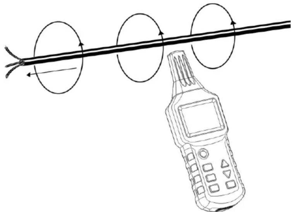
Line drawing of a handheld device connected to a straight cable with three circular motion arrows indicating clockwise motion (no text or symbols)Fig.1
2. DESCRIPTION
2.1 TRANSMITTER
2.1.1 OVERALL DESCRIPTION
text_image
11 10 1 LEVEL CODE 8 ~1888v CODE 8 2 POWER 3 START STOP LEVEL SEL. ▲ CODE SEL. 4 5 9 8 7 6 IEC61010-1 500V CATIII + 500V AC~Fig.2
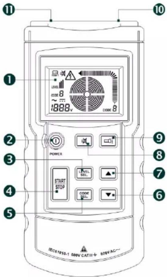
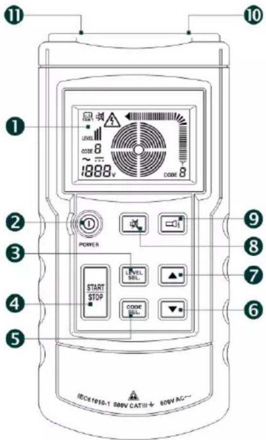
(1) LCD screen.
(2) On/Off key
(3) Key for adjustment / confirmation of the transmit power level (Level I, II or III).
(4) Start / Stop Transmission key.
(5) Key for adjustment/confirmation of the code information to be sent. Press this key for 1 second to activate the code selection mode and press briefly to exit from this mode (the codes F, E, H, D, L, C, Y, and A can be selected; F is the default).
(6) Lower the transmitted power level or change the transmission code.
(7) Raise the transmitted power level or change the transmission code.
(8) Key for activation or de-activation of the silent mode (in silent mode, key presses and the buzzer are silent).
(9) Torch On/Off key.
(10) "+" input/output terminal for measurement of the voltages present and application of the signal to the object being tested.
(11) "COM" input/output terminal. Earthing terminal.
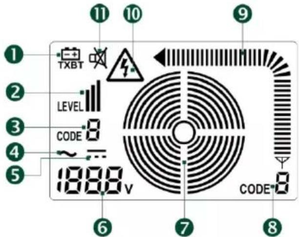
2.1.2 LCD SCREEN
text_image
1 2 3 4 5 TXBT LEVEL CODE 1888 v 6 7 8 9 10 11 CODEFig.3
(1) Symbol indicating that batteries are dead and must be replaced.
(2) Transmitted power level (Level I, II, or III).
(3) Transmission code (F is default).
(4) AC voltage.
(5) DC voltage.
(6) Measured voltage (the device can be used as an ordinary voltmeter; voltage range: 12 to 300V DC or AC).
(7) Transmission status.
(8) Code transmitted.
(9) Strength of transmitted signal.
(10) Voltage present symbol.
(11) Silent mode symbol.
2.2 RECEIVER
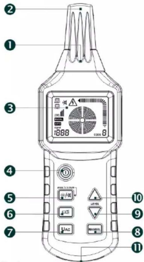
2.2.1 GLOBAL DESCRIPTION
text_image
Labeled diagram of a digital testing device with numbered parts and control buttonsFig.4
(1) Lighting torch.
(2) Head of the sensor.
(3) LCD screen.
(4) On/Off key.
(5) Back-lighting and silent mode On/Off key. Press briefly to activate/de-activate the backlighting and press for 1 second to activate/de-activate the silent mode (in silent mode, key presses are silent and the buzzer is off).
(6) Torch On/Off key.
(7) UAC: Selection of the cable detection mode or of the mains voltage detection mode.
(8) Selection of manual or automatic mode for cable detection.
(9) Adjustment key to decrease receive sensitivity in manual mode.
(10) Adjustment key to increase receive sensitivity in manual mode.
(11) Buzzer.
2.2.2 LCD SCREEN

text_image
① ② ③ ④ ⑤ RXBT TXBT LEVEL MANUAL AUTO signal 1988 ⑥ ⑦ ⑧ CODE ⑨ ⑪ ⑩ ⑪ ⑩Fig.5
(1) Symbol indicating that the receiver batteries are dead and must be replaced.
(2) Symbol indicating that the transmitter battery is dead and must be replaced.
(3) Received signal level (Level I, II, or III).
(4) Manual mode symbol.
(5) Automatic mode symbol.
(6) In automatic mode, this number indicates the strength of the signal; in manual mode, this location displays either "SEL", to indicate that there is no signal, or a value indicating the strength of the signal; in UAC mode, "UAC" is displayed.
(7) Conce ntric circles indicating the preset sensitivity in graphic form. A large number of circles indicates high sensitivity, while a small number indicates a lower sensitivity.
(8) Code received.
(9) Strength of the received signal.
(10) Voltage present symbol.
(11) Silent mode symbol.
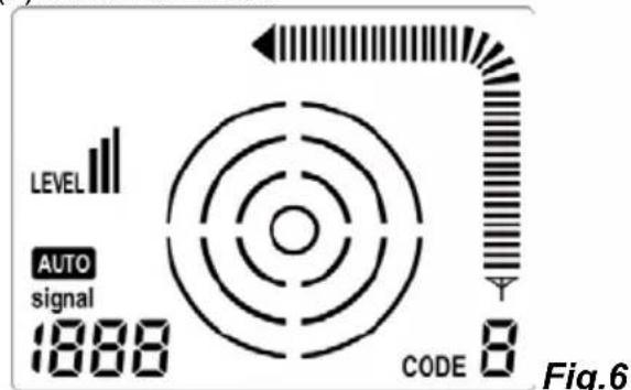
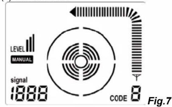
2.2.3 EXAMPLES OF DISPLAY IN CABLE DETECTION MODE
(1) Automatic mode
text_image
LEVEL AUTO signal 1888 CODE 8 Fig.6(3) Mains voltage identification mode
(2) Manual mode
text_image
LEVEL MANUAL signal 1888 CODE 8 Fig.7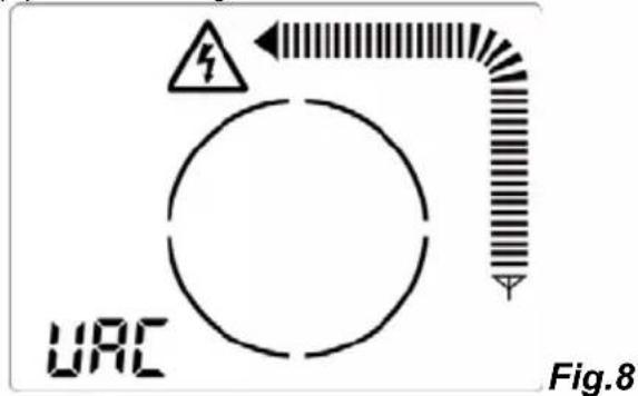
text_image
URC Fig.8- If one of the "On/Off", "Choice of code", and "Level adjustment" keys is active, the other two are inactive.
- If the receiver is in automatic mode, it is possible to change it to manual mode or to mains voltage identification mode at any time.
- If the receiver is in manual mode, the UAC key or the MANUAL key will be active only after exiting from manual mode.
3. USE
3.1 GETTING STARTED
The best way to learn to use the LOCAT NG cable locater is to work the following example:
3.1.1 SETTING UP
natural_image
Line drawing of three handheld devices connected to a cable with a connector, no text or symbols presentFig.9
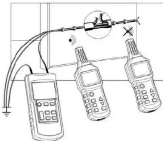
Take a length of sheathed 3-conductor cable having a cross section of 1.5mm2.
Provisionally install 5m of this cable along a wall with staples, on an attachment surface at eye level. The wall must be accessible from both sides.
Choose one of the conductors and create an artificial break 1.5m before the end of the line.
Connect the end of this conductor to terminal (10) of the transmitter using the test leads (provided). Connect terminal (11) of the transmitter to a suitable earth.
All the other conductors of the cable must also be connected to the transmitter and to the same earth (See Fig. 9).
At the far end of the line (of the cable), the conductors must be "open" (not connected to each other).
3.1.2 USE
- Switch the transmitter on using key (2). The LCD display unit of the transmitter displays the first screen and the buzzer beeps twice.
- Press key (3) of the transmitter to enter the transmit level adjustment on the screen, then press the up arrow key (7) or down arrow key (6) to select the transmit level (I, II, or III). After setting this level, press key (3) to exit.
- If you want to change the code transmitted, press key (5) of the transmitter for approximately 1 second, then press the up arrow key (7) or the down arrow key (6) to select the code transmitted (F, E, H, D, L, C, Y, or A; F is default). Press key (5) to exit.
- Then press key (4) to start transmission. The concentric circles (7) on the LCD screen than spread gradually, symbol (8) displays the code of the transmitted signal, and symbol (9) displays the strength of the signal.
- Press key (4) of the receiver to switch it on. The LCD display displays the first screen, the buzzer beeps twice, and the receiver changes to "Automatic Mode" as default.
Move the probe of the receiver slowly along the cable as far as the break. Symbol (3) on the receiver displays the received power level, (8) displays the code transmitted by the transmitter, (9) displays the dynamic strength of the signal, and the buzzer changes pitch with the change of strength of the signal. When the probe of the receiver passes over the break, the strength of the signal displayed by (9) and (6) exhibits an obvious drop, then disappears completely. - To refine the detection, press the MANUAL key (8) of the receiver to change to manual mode, then use keys (9) and (10) to reduce the sensitivity as far as possible while checking that the screen of the receiver can display the transmit code (8) of the transmitter. This, then, is where the break is located.
3.1.3 THE NEXT STEP : THE 2 TRANSMITTER CONNECTION MODES
Only these transmitter connection modes can be used to locate conductors with the LOCAT_NG
Single-pole application:
Connect the transmitter to a single conductor. If the signal transmitted by the transmitter is a high-frequency signal, only one conductor can be detected and traced.
The second conductor is then earthed.
This arrangement causes the flow of a high-frequency current in the conductor and its transmission through the air to earth; this is the same principle used between the transmitter and the receiver for radio broadcasting.
Two-pole application:
This connection can be made to a live or dead mains line. The transmitter is connected to both conductors using the two test leads.
A Connection to a live line:
- Connect the "+" terminal of the transmitter to the conductor connected to the phase
- Connect the other terminal of the transmitter to the neutral line of the mains.
In this case, if there is no load on the mains, the modulated current from the transmitter will flow to the neutral line by coupling via the distributed capacitance of the wires of the line and then return to the transmitter.
Remark:
When the transmitter is connected to a live line, if one of its terminals is connected to a protection earth wire rather than the neutral, the current through the transmitter is added to the leakage current already present in the installation. The resulting total leakage current may then activate the RCD, in other words trip the RCD.
B Connection to a dead line:
- Connect the "+" terminal of the transmitter to one wire of the line,
- Connect the other terminal of the transmitter to the other wire of the line, and then
- At the other end of the line, connect the two wires together.
In this case, the modulated current returns directly to the transmitter through the line.
In another method, the two test leads of the transmitter can be connected to the two ends of a single wire. In addition, since the installation is dead, the protection earth conductor of the line can also be used without risk.
3.2 SINGLE-POLE APPLICATION
To:
Detect breaks in conductors in walls or in a floor;
Locate and trace lines, outlets, junction boxes, switches, etc., in domestic installations;
Locate bottlenecks, twists, deformations, and obstructions in piping installations using a metal wire.
3.2.1 LOCATING AND TRACING LINES AND OUTLETS
Preconditions:
• The circuit must be dead.
- The neutral wire and the protection earth wire must be connected and perfectly operational.
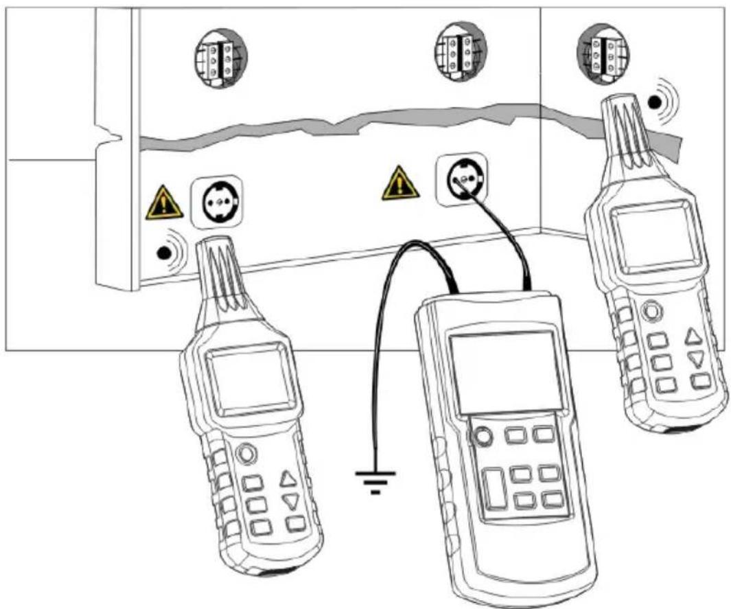
- Connect the transmitter to the phase and to the protection earth wire as shown in Fig. 10.
text_image
Diagram showing three connected devices with warning symbols and grounding, likely illustrating a safety or electrical hazard detection setup.Fig.10
English
Remark:
If the cable supplied by the signals from the transmitter is near other conductors that are parallel to it (example: cable tray, channel, etc.) or is interlaced with or crosses them, the signal may then propagate in these cables and create spurious circuits.
3.2.2 LOCATING BREAKS IN LINES
Preconditions:
• The circuit must be dead.
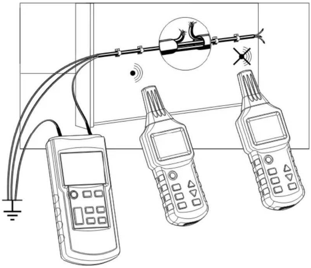
• All the other lines must be earthed as shown in Fig. 11.
- Connect the transmitter to the wire in question and to earth as shown in Fig. 11.
natural_image
Line drawing of three handheld devices connected to a cable with wiring, no text or symbols presentFig.11
Remarks:
- The transition resistance of the break in the line must be greater than 10kOhms.
- Note that, when breaks in multi-conductor cables are traced, all the other wires of the cable or of the shielded conductor must be earthed. This is necessary to prevent cross coupling of the applied signals (by a capacitive effect) on the terminals of the source.
- The earth connected to the transmitter can be an auxiliary earth, the earthing terminal of a power outlet, or a correctly earthed water pipe.
- When the line is traced, the place at which the signal received by the receiver falls off suddenly is the location of the break.
Refine the detection by setting the power level transmitted by the transmitter and the sensitivity of the receiver in manual mode.
3.2.3 LOCATING LINE BREAKS USING TWO TRANSMITTERS
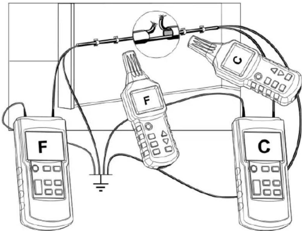
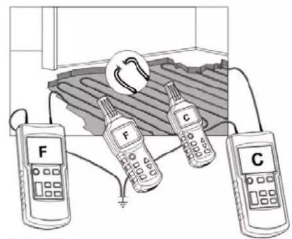
When a line break is located using a transmitter supplying one end of the conductor, its location may not be precise if conditions are unsatisfactory because of a disturbance of the field. The drawbacks described above are readily avoided by using two transmitters (one at each end) to detect line breaks. In this case, each transmitter is set to a different line code, e.g. one transmitter to code F and the other to code C. (The second transmitter, with a different line code, is not included in the kit supplied and must therefore be purchased separately.)
Preconditions:
- The circuit measured must not be live.
• All unused lines must be earthed as shown in Fig. 12. - Connect the two transmitters as shown in Fig. 12.
- The measurement method is identical to that used in §3.1 Getting started
If the transmitters are connected as shown in Fig. 12, the receiver will indicate C to the left of the line break. If the receiver goes beyond the location of the break, to the right, it will display F. If the receiver is placed right on the break, no line code will be displayed, because of the superposition of the signals from the two transmitters.
English
text_image
Diagram of a circuit setup with labeled components F and C, showing connections via wires and a magnified inset of a cable or connector.Fig.12
Remarks:
• The transition resistance of the line break must be greater than 100kOhms.
- Note that, when breaks in multi-conductor cables are traced, all the other wires of the cable or of the shielded conductor must be earthed. This is necessary to prevent cross coupling of the applied signals (by a capacitive effect) on the terminals of the source.
- The earth connected to the transmitter can be a auxiliary earth, the earthing terminal of a power outlet, or a correctly earthed water pipe.
- When the line is traced, the place at which the signal received by the receiver falls off suddenly is the location of the break.
Refine the detection by setting the power level transmitted by the transmitter and the sensitivity of the receiver in manual mode.
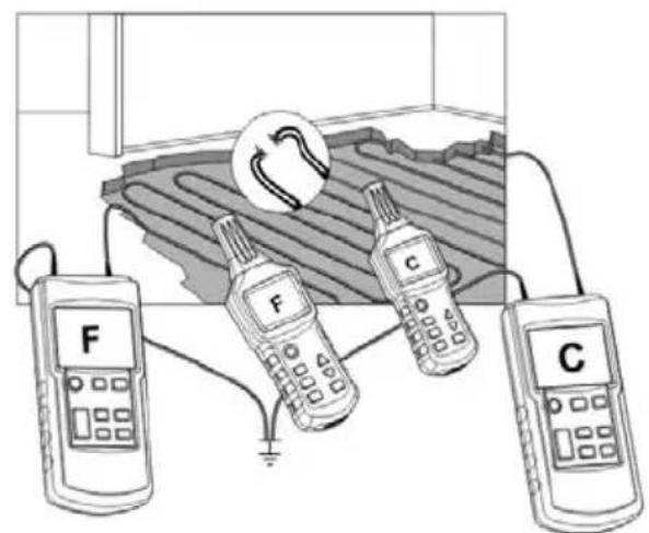
3.2.4 DETECTION OF FAULTS IN AN IN FLOOR HEATING SYSTEM
Preconditions:
• The circuit measured must not be live.
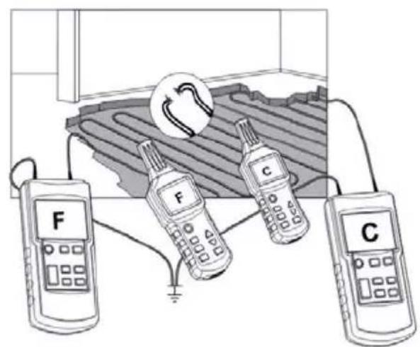
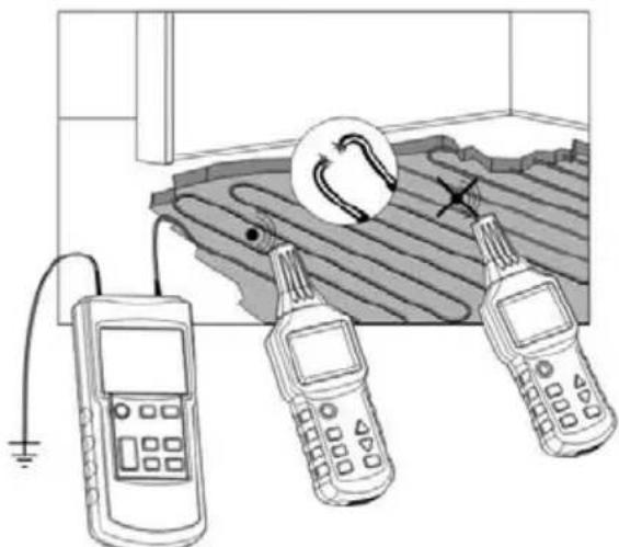
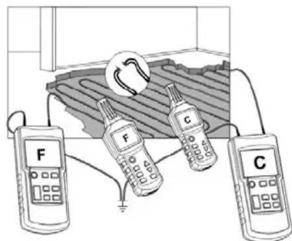
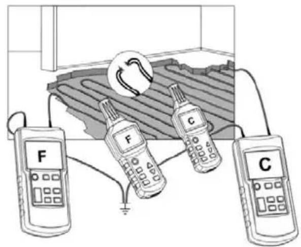
• All unused lines must be earthed as shown in Fig. 13a.
- Connect the two transmitters (if two transmitters are used) as shown in Fig. 13b.
- The measurement method is identical to that used in §3.1 Getting started
natural_image
Illustration of three handheld devices connected to a grid-patterned surface, with one device showing a circular arrow and the other holding a magnifying glass (no text or symbols present)Fig.13a
text_image
Diagram showing three devices labeled F, C, and a circular device with a rotating arrow, connected to a grid-like structure.Fig.13b
- If there is a screen above the heating wires, there may not be an earth connection. If necessary, separate the shielding from the earth connection.
- There must be earthing, and there must be a long distance between the earthing terminal of the transmitter and the line to be located. If this distance is too short, the signal and the line cannot be located precisely.
- A second transmitter is not essential for this application.
For an application with only one transmitter, refer to Fig. 13a.
- When the line is traced, the place at which the signal received by the receiver falls off suddenly is the location of the break.
Refine the detection by setting the power level transmitted by the transmitter and the sensitivity of the receiver in manual mode.
3.2.5 DETECTION OF THE CONSTRICTED (PLUGGED) PART OF A NON-METALLIC PIPE
Preconditions:
• The pipe must be made of a non-conducting material (such as plastic);
• The pipe must not be live;
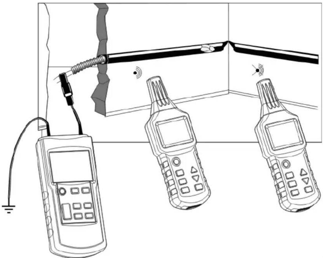
- The transmitter is connected to a metallic helical tube (flexible metallic tube or pipe) and to an auxiliary earth as shown in Fig. 14;
- The measurement method is identical to that used in §3.1 Getting started
natural_image
Line drawing of three handheld devices connected to a wall-mounted device, with no visible text or symbols.Fig.14
Remarks:
- If there is a current in the pipe, cut off its supply and connect it correctly to earth when the pipe is not live.
- One end of the pipe must be correctly earthed, and the earth of the transmitter must be at a certain distance from the pipe to be located. If the estimated distance is too short, the signal and the circuit cannot be located precisely.
- If you have only a helical pipe made of a non-conducting material (fibreglass, PVC, etc.), we suggest inserting a metal wire having a cross section of approximately 1.5mm2 in the non-conducting helical pipe
- When the line is traced, the place at which the signal received by the receiver falls off suddenly is the location of the constriction.
Refine the detection by setting the power level transmitted by the transmitter and the sensitivity of the receiver in manual mode.
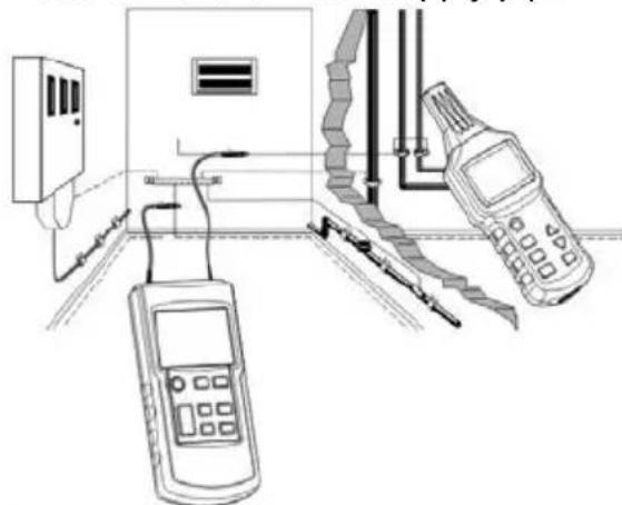
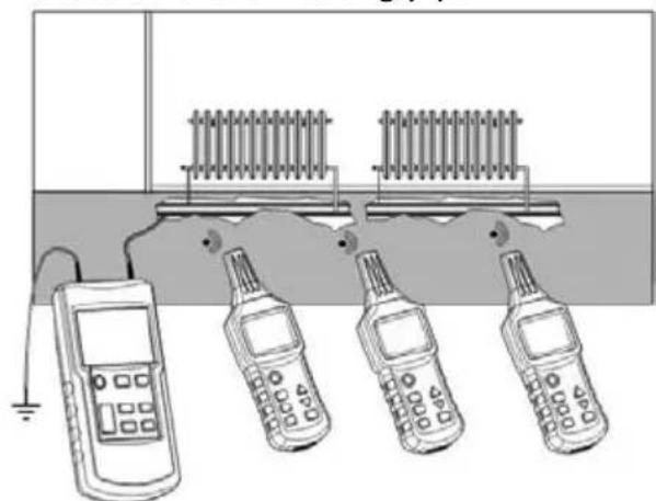
3.2.6 DETECTION OF A METALLIC WATER SUPPLY AND HEATING PIPE
Preconditions:
• The pipe must be conducting, and so metallic (for example galvanized steel);
- The pipe to be detected must not be earthed. There must be a relatively high resistance between the pipe and the ground (otherwise, the detection distance will be very short);
- Connect the transmitter to the pipe to be detected and to earth.
Detection of the water supply pipe
natural_image
Diagram of electrical measurement setup with handheld devices and wiring (no text or labels)Fig.15a
Detection of the heating pipe
natural_image
Illustration of four mobile phones connected to a wall-mounted heating element (no text or symbols visible)Fig.15b
Remarks:
- The transmitter must be earthed at a certain distance from the pipe to be detected. If the distance is too short, the signals and the circuit cannot be located precisely.
English
- To detect a pipe made of a non-conducting material, we suggest first inserting a helical metal tube or a metal wire having a cross section of approximately 1.5mm2 in the pipe, as explained in §3.2.5 Detection of the constricted (plugged) part of a non-metallic pipe
- Refine the detection by setting the power level transmitted by the transmitter and the sensitivity of the receiver in manual mode.
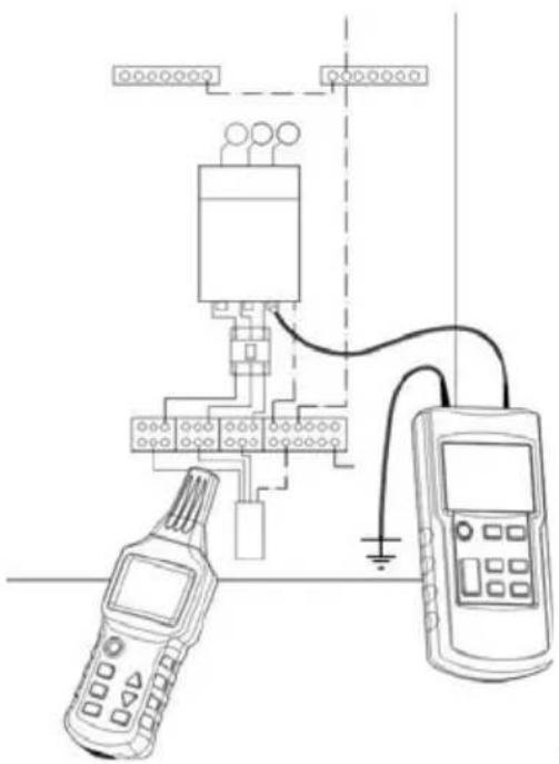
3.2.7 IDENTIFICATION OF SUPPLY CIRCUIT ON THE SAME FLOOR
Preconditions:
• The circuit measured must not be live.
To detect a supply circuit on the same floor, proceed as follows:
- trip the main circuit-breaker of the floor's distribution box;
- In the distribution box, disconnect the neutral wire of the circuit to be identified from the neutral wires of the other circuits;
- Connect the transmitter as shown in figure 16.
natural_image
Pure electrical circuit lines without any symbolsFig.16
Remark:
- Refine the detection by setting the power level transmitted by the transmitter and the sensitivity of the receiver in manual mode.
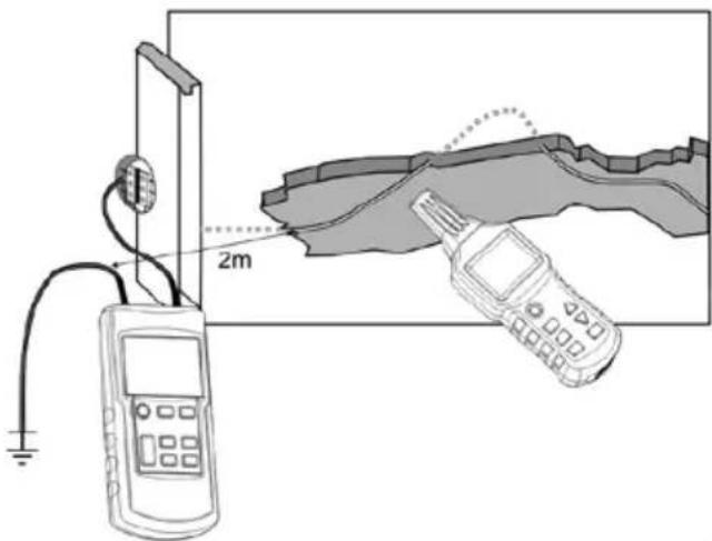
3.2.8 TRACING AN UNDERGROUND CIRCUIT
Preconditions:
• The circuit measured must not be live.
- Connect the transmitter as shown in Fig. 17;
• The transmitter must be correctly earthed;
- Select the automatic mode of the receiver;
• Use the power of the signal displayed to find and trace the circuit.
text_image
2mFig.17
Remarks:
- The distance between the earth wire and the circuit to be located must be as long as possible. If this distance is too short, the signals and the circuit cannot be located precisely.
- The depth of detection is strongly influenced by the earthing conditions. Select suitable receive sensitivities to locate the circuit precisely.
- If you move the receiver slowly along the circuit to be located, you will see that the screen changes somewhat. The most powerful signals represent the precise position of the circuit.
- The longer the distance between the signals transmitted (by the transmitter) and the receiver, the lower the power of the signals received and the lower the depth of detection.
3.3 TWO-POLE APPLICATIONS
3.3.1 CLOSED-CIRCUIT APPLICATIONS
These can be applied to both live and dead circuits:
In dead circuits, the transmitter merely sends coded signals to the circuits to be detected.
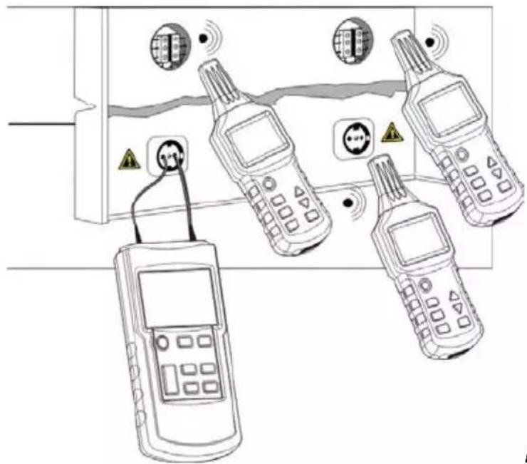
In live circuits, the transmitter not only sends coded signals to the circuits to be detected, but also measures the voltage present, as shown in figure 18:
text_image
Diagram showing four mobile phones connected to a device with warning symbols and signal waves, likely illustrating a surveillance or monitoring system.Fig.18
Remarks:
- This method is ideal for locating outlets, switches, fuses, etc., in electrical installations that have sub-distribution electrical cabinets.
- The depth of detection varies according to the medium in which the cable is located and according to the manner of use. It is generally less than 0.5m.
- Adjust the power transmitted by the transmitter according to the various radii of detection.
3.3.2 SEARCH FOR FUSES
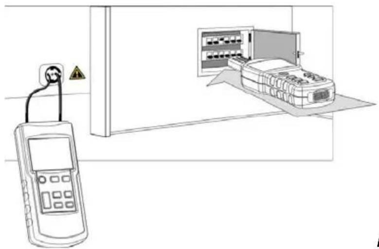
The transmitter is connected to the phase and neutral conductors of the circuit of which the protection fuse is to be located.
The use of the connection accessories (for mains outlet, for sockets) is strongly recommended.
Preconditions:
- Trip all the circuit-breakers of the distribution box;
- Connect the transmitter as shown in figure 19.
natural_image
Line drawing showing a handheld device connected to an electrical panel with warning symbol (no text or labels)Fig.19
Remarks:
- The identification and location of the fuses are strongly influenced by the condition of the wiring of the distribution frame. In order to locate fuses as precisely as possible, it may be necessary to open or remove the cover of the distribution frame, in order to isolate the fuse supply wire.
- During the search process, the fuse delivering the most powerful and most stable signals is the one sought. Because of the coupling of the connections, the detector can detect signals from other fuses, but their power is relatively low.
- During the detection, it is best to place the probe of the detector on the input of the fuse holder in order to obtain the best detection result.
- Adjust the power transmitted by the transmitter according to the various radii of detection.
- Select manual mode on the receiver and a suitable receive sensitivity to locate the circuit precisely.
3.3.3 SEARCH FOR A SHORT-CIRCUIT
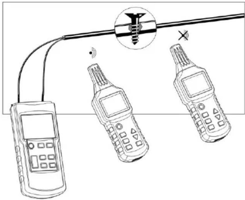
Preconditions:
• The circuit must be dead.
- Connect the transmitter as shown in figure 20.
- The measurement method is identical to that used in §3.1 Getting started
natural_image
Line drawing of three mobile phone devices connected to a cable with a screwdriver (no text or symbols)Fig.20
Remarks:
- During searches for short-circuits in sheathed wires and cables, the depths of detection vary because the sheathed wires are twisted together in the sheath. Experience has shown that only short-circuits having an impedance less than 20ohms can be detected correctly. The impedance of the short-circuit can be measured with a multimeter.
- During the detection process along the circuit, if the signals received are suddenly attenuated, the position detected is where the short-circuit is located.
- If the impedance of the short-circuit is greater than 20ohms, try using the method of searching for a break in a circuit (§3.2.2 Locating breaks in lines) to find the court-circuit.
3.3.4 DETECTION OF RATHER DEEP UNDERGROUND CIRCUITS
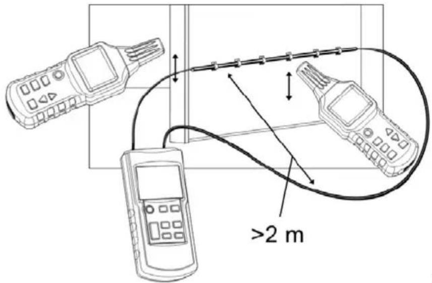
The magnetic field produced by the signal from the transmitter is strongly conditioned by the shape and size (area) of the loop formed by the "forward" conductor (connected to the "+" of the transmitter) and the "return" conductor (connected to the other terminal of the transmitter).
For this reason, in two-pole applications on a multi-conductor cable (for example 3 × 1.5 mm^2 ), the depth of detection is severely limited. Since the two conductors are very close together, the area of the loop is often insufficient.
In this case, it is best to use an "auxiliary" conductor, not one of the conductors of the multi-conductor cable, for the return path.
The important point is that the distance between the "forward" conductor and the "return" conductor should be greater than the depth underground, and in practice this distance is routinely at least 2m.
Preconditions:
• The circuit must be dead;
- Connect the transmitter as shown in Fig. 21;
- The distance between the supply line and the loopback line must be at least 2\~2.5m;
- The measurement method is identical to that used in §3.1 Getting started
text_image
>2 mFig.21
Remark:
- In this application, the influence of the moisture in the floor or wall on the depth of detection is negligible.
3.3.5 SORTING OR IDENTIFICATION OF CONDUCTORS BY PAIR
Preconditions:
• The circuit must be dead.
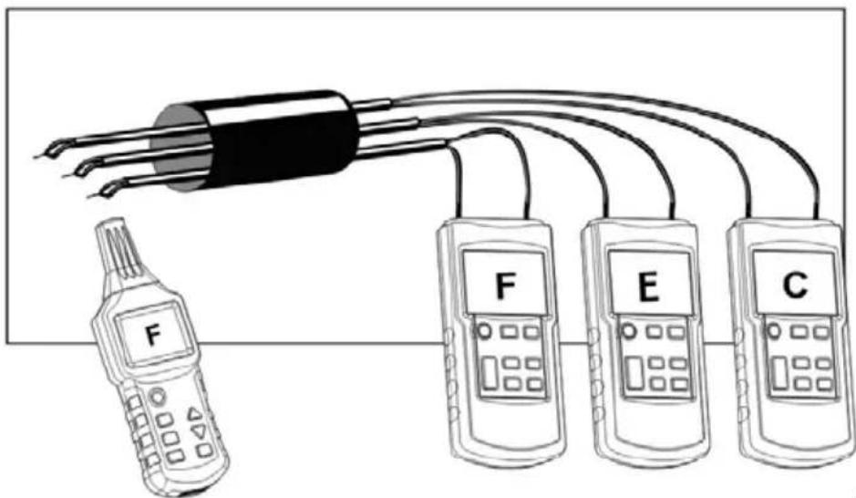
- The ends of the wires of each pair must be twisted together and be mutually conducting; each pair remains insulated from the others.
- Connect the transmitter as shown in Fig. 22.
• The measurement method is the same as in the example.
text_image
Diagram showing a device connected to four labeled thermometers (F, E, C) with wires extending from it.Fig.22
Remarks:
- The ends of each pair must be twisted together (pairwise) in order to ensure perfect continuity.
- When several transmitters are used, each transmitter must be set to a different transmission code
- If only one transmitter is used, make several measurements with different connections between the transmitter and the various pairs.
3.4 WAY OF INCREASING THE EFFECTIVE RADIUS OF DETECTION OF LIVE CIRCUITS
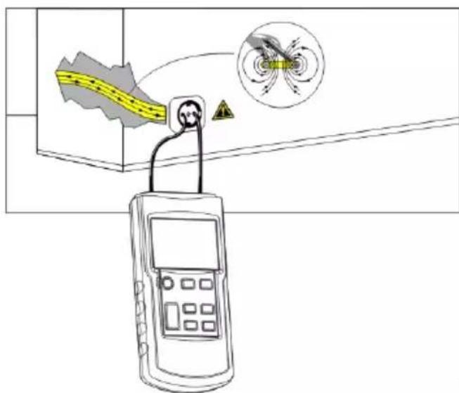
The magnetic field produced by the signal from the transmitter is strongly conditioned by the shape and size (area) of the loop formed by the "forward" conductor (connected to the "+" of the transmitter) and the "return" conductor (connected to the "earth" terminal of the transmitter).
In consequence, in a configuration where the transmitter is connected to the phase and neutral conductors, constituted by two parallel wires (as shown in Fig. 23), the effective radius (distance) of detection is not more than 0.5m.
text_image
Diagram showing a handheld device connected to a yellow waveform signal and a magnified circular diagram with directional arrows, likely illustrating an electrical or measurement setup.Fig.23
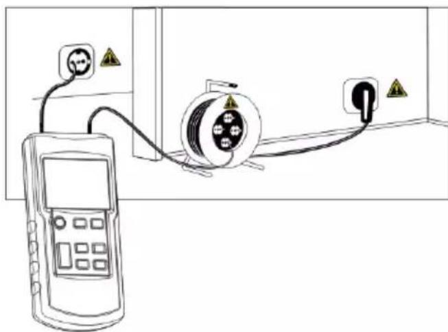
In order to eliminate this effect, connect as shown in Fig. 24, where the loopback line uses a separate cable to increase the effective radius of detection.
With a cable extender (see Fig. 24), it is possible to obtain a detection distance of up to 2.5 ~m .
natural_image
Diagram showing a power meter connected to a cable with warning symbols, next to an electrical outlet (no text or labels present)Fig.24
English
3.5 IDENTIFICATION OF THE MAINS VOLTAGE AND SEARCH FOR BREAKS IN THE CIRCUIT
This application does not need the transmitter (unless you want to use its voltmeter function to measure the voltage in the circuit precisely.).
Preconditions:
• The circuit must be connected to mains and live.
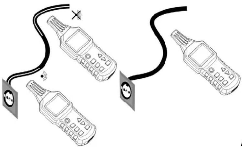
• The measurement must be made as shown in Fig. 25;
- Set the receiver to the "Identification of mains voltage" mode (designated "UAC mode").
natural_image
Three identical mobile phone devices connected by a black cable, each with a circular connector and signal icon (no text or symbols present)Fig.25
Remarks:
- The AC signals detected by the receiver in UAC mode indicate only whether the circuit is live; for a precise measurement of the voltage, use the voltmeter function of the transmitter.
- During the search for the ends of several supply lines, the lines must be connected separately, one by one.
- The number of bars indicating the strength of the received signal and the frequency of the audible signal emitted depend on the voltage in the circuit to be detected and on the distance from this circuit. The higher the voltage and the shorter the distance from the circuit, the more bars are displayed and the higher the frequency of the audible signal.
4. OTHER FUNCTIONS
4.1 VOLTMETER FUNCTION OF THE TRANSMITTER
If the transmitter is connected to a live circuit and the voltage measured is greater than 12V, the bottom left part of the screen of the transmitter displays the true voltage with the standard symbols used to distinguish AC from DC (see (4), (5), and (6) in §2.1.1 Global description of the transmitter), and the upper part of the screen displays the lightning flash symbol in a triangle (see (10) in §2.1.1 Global description of the transmitter). The identification range is 12\~300V, DC or AC (50\~60Hz).
4.2 TORCH FUNCTION
Press button (9) of the transmitter or (6) of the receiver to activate the torch; press again to de-activate the function.
Press the back-light button (5) of the receiver to switch the back-light on; press the button again to switch it off. The transmitter does not have a back-light function.
4.4 ACTIVATION / DE-ACTIVATION OF THE BUZZER
4.4.1 TRANSMITTER
Press the silent mode button (8) of the transmitter to de-activate the buzzer, which will then remain silent when keys are pressed. Press this button again to de-activate the silent mode of the transmitter and reactivate the buzzer.
4.4.2 RECEIVER
Press the back-light/silent mode button (5) of the receiver for more than one second to de-activate the audible signal. Press the back-light/silent mode button (5) of the receiver for one second to de-activate the silent mode and the buzzer will once again be active.
4.5 AUTOMATIC POWER-OFF FUNCTION
4.5.1 TRANSMITTER
The transmitter does not have an automatic power-off function.
4.5.2 RECEIVER
If you have not pressed a button on the receiver for 10 minutes, the receiver automatically switches itself off. Press the On/Off button (2) to switch it back on.
5. CHARACTERISTICS
5.1 TECHNICAL CHARACTERISTICS OF THE TRANSMITTER
| Output signal frequency | 125kHz |
| Range of identification of external voltage | 12~300V DC ± 2.5%; 12~300V AC (50~60Hz) ± 2.5% |
| Screen | LCD with display of functions and bargraph |
| Type of overvoltage | CAT III - 300V pollution class 2 |
| Power supply | 1 9V battery, IEC 6LR61 |
| Consumption | Between approximately 31mA and 115mA depending on use; |
| Fuse | F 0.5 A 500V, 6.3 ×32mm |
| Operating temperature range | 0°C to 40°C, with a maximum relative humidity of 80% (without condensation). |
| Storage temperature | -20°C to +60°C, with a maximum relative humidity of 80% (without condensation). |
| Altitude | 2 000m max. |
| Dimensions (H × W × D) | 190mm × 89mm × 42.5mm |
| Weight | Approximately 360g without battery / approximately 420g with battery |
5.2 TECHNICAL CHARACTERISTICS OF THE RECEIVER
| Depth of detection | Single-pole application: 0 to approximately 2m two-pole application: 0 to approximately 0.5m Single loopback line: Up to 2.5m |
| Identification of mains voltage | Approximately 0~0.4m |
| Screen | LCD, with display of functions and bargraph |
| Power supply | 6 1.5V battery, IEC LR03 |
| Consumption | between approximately 32mA and 89mA depending on use; |
| Operating temperature range | 0°C to 40°C, , with a maximum relative humidity of 80% (without condensation) |
| Storage temperature | -20°C to +60°C, , with a maximum relative humidity of 80% (without condensation) |
| Altitude | 2,000m max. |
| Dimensions (H × W × D) | 241.5mm × 78mm × 38.5mm |
| Weight | approximately 280g without battery/ approximately 360g with battery |
Remark:
- The depth of detection also depends on the material and the specific application.
5.3 COMPLIANCE WITH INTERNATIONAL STANDARDS
| Electrical safety | Compliant with standards EN 61010-1 |
| Electromagnetic compatibility | Compliant with standard EN 61326-1 |
6. MAINTENANCE

Other than the fuse and the batteries, the instrument contains no that could be replaced by a person who is not trained and certified. Any non-certified work, or replacement of a part by an "equivalent", might gravely impair safety.
6.1 CLEANING
Wipe the transmitter with a cloth dampened with clean water or with a neutral detergent, then wipe dry with a dry cloth.
Do not use the device again until it is completely dry.
6.2 REPLACING THE BATTERIES
If the dead battery symbol on the screen blinks (on the transmitter or on the receiver) and the buzzer emits a warning, the battery(ies) must be replaced.
Proceed as follows to replace the battery(ies) (of the transmitter or of the receiver):
- Switch the device off and disconnect it from all circuits being measured;
- Unscrew the screw on the back of the device and remove the cover of the battery compartment
- Remove the dead (battery(ies);
• Install the new battery(ies); watch out for the polarity; - Put the cover of the battery compartment back in place and screw the screw back in.
Checking the fuse of the transmitter
The fuse of the transmitter protects it from overloads and from operator errors. If the fuse has blown, the transmitter can transmit only weak signals.
If the self-test of the transmitter is OK and the signal transmitted is weak, transmission functions but the fuse has blown. If no signal is transmitted during the self-test, and if the battery voltage is normal, the transmitter is damaged and must be repaired by specialized technicians.
Methods and specific steps in checking the fuse of the transmitter:
- Disconnect all circuits being measured that are connected to the transmitter;
- Switch the transmitter on and set it to transmit mode;
- Set the power transmitted by the transmitter to Level I;
- Connect a cord between the two terminals of the transmitter;
- Switch the transmitter on to search for the signals from the test cord, and move the probe of the receiver towards the test cord;
- If the fuse has not blown, the value displayed by the receiver will double.
If it has blown, replace it yourself with a fuse of the same model. This fuse is of a simple fast-blow type, so do not replace it with a slow-blow model with helical wire, since then the safety of the device could no longer be guaranteed.
6.3 METROLOGICAL CHECK
Like all measuring or testing devices, the instrument must be checked regularly.
This instrument should be checked at least once a year. For checking and calibration, contact one of our accredited metrology laboratories (information and contact details available on request), at our Chauvin Arnoux subsidiary or the branch in your country.
6.4 REPAIR
For all repairs before or after expiry of warranty, please return the device to your distributor.
7. WARRANTY
The equipment is warranted against defects of materials or workmanship, in accordance with the general terms of sale.
During the warranty period (1 year), the instrument must be repaired only by the manufacturer, which reserves the right to choose between repairing it and replacing it, completely or partially.
If the equipment is sent back to the manufacturer, carriage is paid by the customer.
The warranty does not apply in the following cases:
• Inappropriate use of the equipment or use with incompatible equipment;
- Modifications made to the equipment without the explicit permission of the manufacturer's technical staff;
• Work done on the device by a person not approved by the manufacturer;
- Adaptation to a particular application not anticipated in the definition of the equipment or not indicated in the user's manual;
- Damage caused by shocks, falls, or floods.
8. TO ORDER
8.1 DELIVERY CONDITION
• 1 C.A. 6681E transmitter
• 1 C.A. 6681R receiver
- 1 set of 2 red/black leads 1.5m long, insulated ∅4mm straight banana plug/insulated ∅4mm elbow banana plug
• 1 set of 2 red/black crocodile clips
• 1 peg for earthing
• 1 9V 6LR61 alkaline battery
• 6 1.5V LR03 (or AAA) alkaline batteries
- 1 adapter plug for B22 bayonet socket/2 (red/black) insulated ∅4mm straight banana plugs
- 1 connection adapter for mains outlet/2 (red/black) insulated ∅4mm straight banana plugs
- 1 adapter plug for E27 screw socket/2 (red/black) insulated ∅4mm straight banana plugs
• 1 User manual in 5 languages
All in a carrying case.
Deutsch
natural_image
Line drawing of a handheld device connected to a wire with three circular motion arrows indicating rotational or bidirectional motion (no text or symbols)Abb.1
2. BESCHREIBUNG
2.1 SENDER
text_image
Diagram of a digital multimeter with labeled parts including control panel, display screen, and function buttonsAbb.4
natural_image
Line drawing of three mobile phones connected to a power outlet, with no visible text or symbolsAbb.9
text_image
Diagram showing three connected devices with warning symbols and electrical connections, likely illustrating a safety or monitoring system.Abb.10
Hinweis:
natural_image
Line drawing of three handheld devices connected to a cable with wiring, showing signal propagation and control signals (no text or symbols)Abb.11
Hinweise:
text_image
Diagram of a circuit setup with labeled components F and C, showing connections via wires and a magnified inset of a cable or connector.Abb.12
Hinweise:
natural_image
Illustration of three mobile phones connected to a grid-patterned surface, with one showing a curved arrow (no text or symbols present)Abb.13a
text_image
Diagram showing three mobile phones (F, C, and an unlabeled device) connected to a grid device with a circular arrow indicating rotation or signal flow.Abb.13b
natural_image
Line drawing of three handheld devices connected to a wall-mounted device, with no visible text or symbols.Abb.14
Hinweise:
natural_image
Line drawing of electrical testing setup with devices and wiring (no text or symbols)Abb.15a
natural_image
Illustration of four mobile phones connected to a wall-mounted heating element (no text or symbols visible)Abb.15b
Hinweise:
natural_image
Pure electrical circuit lines without any symbolsAbb.16
Hinweis:
text_image
Diagram showing four mobile phones connected to a device with warning symbols and signal waves, likely illustrating a surveillance or monitoring system.Abb.18
Hinweise:
natural_image
Line drawing of a handheld device connected to an electrical panel with warning symbol (no text or labels)Abb.19
Hinweise:
natural_image
Line drawing of three mobile phone devices connected to a cable with a screwdriver (no text or symbols)Abb.20
Hinweise:
text_image
Diagram showing a device connected to four labeled thermometers (F, E, C) via wires, likely illustrating a measurement or testing setup.Abb.22
Hinweise:
text_image
Diagram showing a handheld device connected to a yellow cable with warning symbol and a magnified view of a device emitting electric field lines.Abb.23
natural_image
Diagram showing a handheld device connected to a cable with two outlets and warning symbols (no text or labels present)Abb.24
natural_image
Line drawing of three mobile phone devices connected by wires, no text or symbols presentAbb.25
Hinweise:
natural_image
Line drawing of a handheld device connected to a straight cable with three circular motion arrows indicating clockwise motion (no text or symbols)Fig.1
2. DESCRIZIONE
2.1 EMETTITORE
text_image
Diagram of a digital handheld device with labeled parts including control panel, display screen, and function buttonsFig.4
text_image
① ② ③ ④ ⑤ RGBT TXBT LEVEL MANUAL AUTO signal 1988 ⑥ ⑦ ⑧ CODE 8 ⑪ ⑩ ⑨Fig.5
text_image
LEVEL AUTO signal 1888 CODE 8 Fig.6text_image
LEVEL MANUAL signal 1888 CODE 8 Fig.7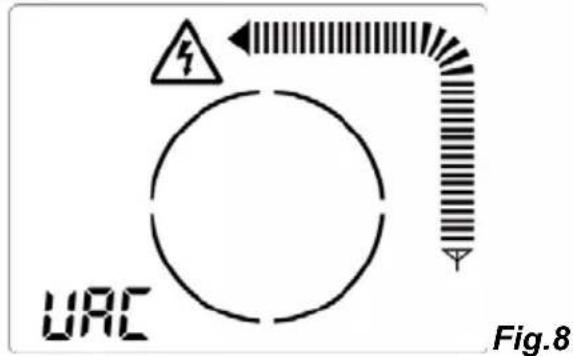
text_image
URC Fig.82.2.4 OSSERVAZIONI CONCERNENTI IL FUNZIONAMENTO DEI TASTI
natural_image
Line drawing of three handheld devices connected to a cable with a magnified inset showing wiring (no text or symbols)Fig.9
text_image
Diagram showing three connected devices with warning symbols and grounding, likely illustrating a safety or electrical hazard detection setup.Fig.10
Italiano
Osservazione:
natural_image
Line drawing of three handheld devices connected to a cable with wiring, showing signal propagation (no text or symbols)Fig.11
Osservazioni:
text_image
Diagram of a circuit setup with labeled components F and C, showing connections via wires and a magnified inset of a cable or connector.Fig.12
Osservazioni:
natural_image
Illustration of three mobile phones connected to a grid-patterned surface, with one device emitting a circular arrow (no text or symbols present)Fig.13a
text_image
Diagram showing three devices labeled F, C, and C connected to a grid with a circular arrow indicating rotation or signal flow.Fig.13b
natural_image
Line drawing of three handheld devices connected to a wall-mounted device, with no visible text or symbols.Fig.14
Osservazioni:
natural_image
Diagram of electrical measurement setup with handheld devices and wiring (no text or labels)Fig.15a
natural_image
Illustration of four mobile phones connected to a wall-mounted panel, with a power meter and ground connections (no text or symbols)Fig.15b
Osservazioni:
text_image
Diagram of a measurement setup with two handheld devices connected to a central device and connected to a digital meter.Fig.16
Osservazione:
text_image
Diagram showing a handheld device connected to a 2m measurement setup with a mobile phone and a hand holding a device.Fig.17
Osservazioni:
text_image
Diagram showing four mobile phones connected to a device with warning symbols and signal waves, likely illustrating a surveillance or monitoring system.Fig.18
Osservazioni:
natural_image
Line drawing showing a handheld device connected to an electrical panel with warning symbol (no text or labels)Fig.19
Osservazioni:
natural_image
Line drawing of three mobile phone devices connected to a cable with a screw and signal icon (no text or symbols)Fig.20
Osservazioni:
text_image
Diagram showing a device connected to four labeled thermometers (F, E, C) via wires, likely representing a measurement or testing setup.Fig.22
Osservazioni:
text_image
Diagram showing a handheld device connected to a yellow waveform signal and a magnified circular diagram with directional arrows, likely illustrating an electrical or measurement setup.Fig.23
text_image
Diagram showing electrical connections with a power meter, cable, and socket, all marked with warning symbolsFig.24
Italiano
natural_image
Diagram of three mobile phone devices connected by a cable, showing signal propagation (no text or symbols)Fig.25
Osservazioni:
natural_image
Line drawing of a handheld device with three circular motion arrows around a straight line, no text or symbols present.Fig.1
2. DESCRIPCIÓN
2.1 TRANSMISOR
text_image
Labeled diagram of a handheld electronic device with numbered parts and control buttonsFig.4
text_image
LEVEL AUTO signal 1888 CODE 8 Fig.6text_image
LEVEL MANUAL signal 1888 CODE 8 Fig.7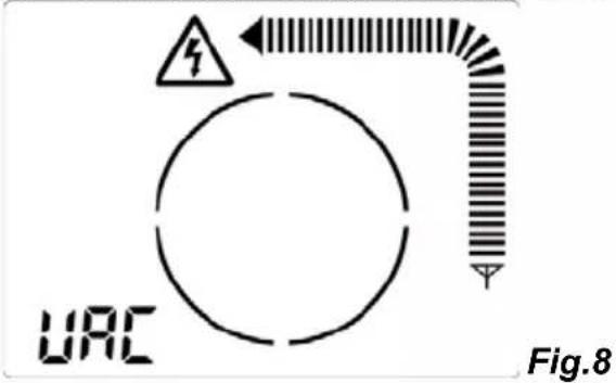
text_image
URC Fig.82.2.4 OBSERVACIONES ACERCA DEL FUNCIONAMIENTO DE LAS TECLAS
natural_image
Line drawing of three handheld devices connected to a cable with a magnified inset showing a connector (no text or symbols)Fig.9
text_image
Diagram showing three connected devices with warning symbols and electrical connections, likely illustrating a safety or monitoring system.Fig.10
Observación:
natural_image
Line drawing of three handheld devices connected to a cable with wiring, showing signal propagation and wiring connections (no text or symbols)Fig.11
Observaciones:
text_image
Diagram of a smart electrical testing setup with three devices labeled F, C, and connected by wires and probes.Fig.12
Observaciones:
natural_image
Illustration of three mobile phones connected to a grid-patterned surface, with one showing a curved arrow (no text or symbols present)Fig.13a
text_image
Diagram showing three mobile phones (F, C, F) connected to a rack with a circular arrow indicating rotation or signal flow.Fig.13b
natural_image
Line drawing of three handheld devices connected to a wall-mounted device, with no visible text or symbols.Fig.14
Observaciones:
natural_image
Diagram of electrical testing setup with meters, probes, and wiring (no text or labels)Fig.15a
natural_image
Diagram of four handheld devices connected to a wall-mounted panel, no text or symbols presentFig.15b
Observaciones:
text_image
Technical diagram showing electrical measurement setup with handheld devices and connected devices, including a central device and power supply connections.Fig.16
Observación:
text_image
Diagram showing four mobile phones connected to a device with warning symbols and signal icons, likely illustrating wireless communication or safety monitoring.Fig.18
Observaciones:
natural_image
Line drawing showing a handheld device connected to an electrical panel with warning symbol (no text or labels)Fig.19
Observaciones:
natural_image
Line drawing of three mobile phone devices connected to a cable with a screw and signal icon (no text or symbols)Fig.20
Observaciones:
text_image
Diagram showing a device connected to four labeled thermometers (F, E, C) with wires extending from it.Fig.22
Observaciones:
text_image
Diagram showing a handheld device connected to a yellow cable with warning symbol, alongside an inset image of a device emitting a device with a warning symbol.Fig.23
text_image
Diagram showing electrical connections with a power meter, cable, and socket, each marked with warning symbolsFig.24
natural_image
Diagram of three mobile phone devices connected by wires, showing signal propagation (no text or symbols)Fig.25
Observaciones:
Unit 1 Nelson Ct - Flagship Sq - Shaw Cross Business Pk
DEWSBURY – West Yorkshire – WF12 7TH
200 Foxborough Blvd. - Foxborough - MA 02035
Tel: (508) 698-2115 - Fax: (508) 698-2118
www.chauvin-arnoux.com