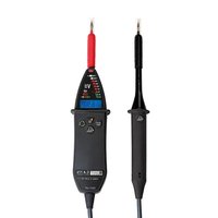
C.A 773 - Measuring equipment CHAUVIN ARNOUX - Free user manual and instructions
Find the device manual for free C.A 773 CHAUVIN ARNOUX in PDF.


| Product type | Bipolar voltage detector |
| Brand | Chauvin Arnoux |
| Model | C.A 773 |
| Dimensions (device) | 228 x 60 x 39 mm |
| Dimensions (probe tip) | 218 x 35 x 25 mm |
| Weight | Approx. 350 g |
| Power supply | 2 alkaline batteries 1.5 V type AA/LR6 |
| Battery life | 2,500 measurements of 10 seconds |
| Main functions | AC/DC voltage detection (12-1000 VAC / 1400 VDC), continuity test, phase detection, phase rotation, 30 mA load switching, measurement point lighting |
| Display | Bar graph and backlit digital display |
| Measurement category | CAT IV 1000 V |
| Standards | IEC 61243-3, IEC 61010-1, NF C 18-510 |
| Protection rating | IP65, IK06 |
| Operating temperature | -15 to +45°C |
| Storage temperature | -40 to +70°C |
| Humidity | 20 to 95% RH |
| Maintenance and cleaning | Soft cloth and soapy water, avoid alcohol and solvent |
| Safety | Double insulation, overload protection, mandatory self-test |
| Spare parts and repairability | Optional probe tips (IP2X), user-replaceable batteries, repairs by authorized personnel |
| Warranty | 24 months |
| Supplied accessories | Red/black probes, protective cap, Velcro fastening, batteries, 5-language manual, certificate |
Frequently Asked Questions - C.A 773 CHAUVIN ARNOUX
User questions about C.A 773 CHAUVIN ARNOUX
0 question about this device. Answer the ones you know or ask your own.
Ask a new question about this device
Download the instructions for your Measuring equipment in PDF format for free! Find your manual C.A 773 - CHAUVIN ARNOUX and take your electronic device back in hand. On this page are published all the documents necessary for the use of your device. C.A 773 by CHAUVIN ARNOUX.
USER MANUAL C.A 773 CHAUVIN ARNOUX
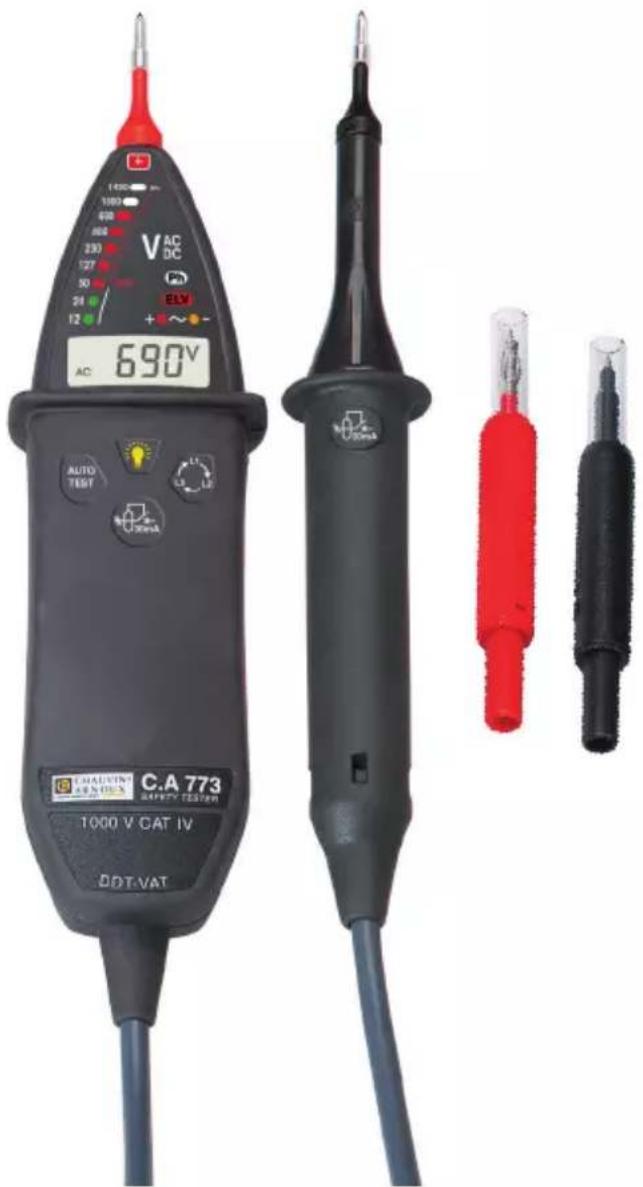
C.A 773 C.A 773 IP2X
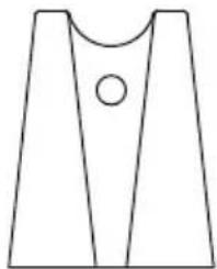
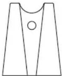
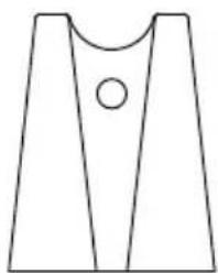
Capuchon
1.2. OPTIONS
Sacoche de transport
Dimensions (L x I x P)
Thank you for purchasing a C.A 773 or C.A 773 IP2X voltage detector.
For best results from your instrument:
■ read these operating instructions carefully,
■ comply with the precautions for use.

WARNING, risk of DANGER! The operator must refer to these instructions whenever this danger symbol appears.

Equipment protected by double insulation.

Equipment suitable for live work.

Battery.

Earth.

The CE marking indicates conformity with European directives, in particular LVD and EMC.

The rubbish bin with a line through it indicates that, in the European Union, the product must undergo selective disposal in compliance with Directive WEEE 2002/96/EC. This equipment must not be treated as household waste.
Definition of measurement categories
■ Measurement category IV corresponds to measurements taken at the source of low-voltage installations.
Example: power feeders, counters and protection devices.
■ Measurement category III corresponds to measurements on building installations.
Example: distribution panel, circuit-breakers, machines or fixed industrial devices.
■ Measurement category II corresponds to measurements taken on circuits directly connected to low-voltage installations.
Example: power supply to domestic electrical appliances and portable tools.
CONTENTS
-
Delivery condition ...... 24
-
Introduction...... 26
-
Use 29
-
Characteristics.... 37
-
Maintenance....40
-
Warranty 41
This device is protected against voltages up to 1000V with respect to earth in measurement category IV.
The protection provided by the device may be compromised if it is used other than as specified by the manufacturer and so endanger the user.
■ Do not exceed the maximum rated voltage and current and the measurement category. Do not use your instrument on networks of which the voltage or category exceeds those stated.
■ Comply with the conditions of use, namely the temperature, the humidity, the altitude, the degree of pollution, and the place of use.
■ When handling the test probes, keep your fingers behind the physical guard.
■ Use connection accessories of which the measurement category and service voltage are at least equal to those of the device.
■ Do not use the device if it is open, damaged, or poorly reassembled, or its accessories if they seem to be damaged.
■ The device must be kept clean so that the condition of the cable insulators, housing, and accessories can be checked. Any component whose insulator is damaged (even partially) must be sent for repair or scrapped.
■ The device is designed to be used by qualified personnel and in compliance with national safety rules.
■ We recommend wearing personal protective equipment when the environment in which the device is used makes it necessary.
■ All troubleshooting and metrological checks must be done by competent, accredited personnel.
SAFETY ADVICES
■ Depending on the internal impedance of the voltage detector there will be a different capability of indicating the presence or absence of operating voltage in case of the presence of interference voltage.
A voltage detector of relatively low internal impedance, compared to the reference value of 100 kΩ, will not indicate all interference voltages having an original voltage value above the ELV level. When in contact with the parts to be tested, the voltage detector may discharge temporarily the interference voltage to a level below the ELV, but it will be back to the original value when the voltage detector is removed.
- When the indication “voltage present” does not appear, it is highly recommended installing earthing equipment before work.
A voltage detector of relatively high internal impedance, compared to the reference value of 100 kΩ, may not permit to clearly indicate the absence of operating voltage in case of presence of interference voltage.
- When the indication “voltage present” appears on a part that is expected to be disconnected of the installation, it is highly recommended confirming by another means (e.g. use of an adequate voltage detector, visual check of the disconnecting point of the electric circuit, etc.) that there is no operating voltage on the part to be tested and to conclude that the voltage indicated by the voltage detector is an interference voltage.
A voltage detector declaring two values of internal impedance has passed a performance test of managing interference voltages and is (within technical limits) able to distinguish operating voltage from interference voltage and has a means to directly or indirectly indicate which type of voltage is present.
1. DELIVERY CONDITION
Voltage detector C.A 773
Delivered with:
■ one red test probe ∅ 2 mm,
■ one black test probe ∅ 2 mm,
■ one protective cap for the test probes,
■ one Velcro fastener,
■ two alkaline batteries (AA or LR6)
■ one user's manual in five languages,
■ a test certificate.
Voltage detector C.A 773 IP2X
Delivered with:
■ one red IP2X test probe ∅ 4 mm,
■ one black IP2X test probe ∅ 4 mm,
■ one Velcro fastener,
■ two alkaline batteries (AA or LR6)
■ one user's manual in five languages,
■ a test certificate.
1.1. ACCESSORIES AND SPARE PARTS
Test probes ∅ 2 x 4 mm (one red and one black)
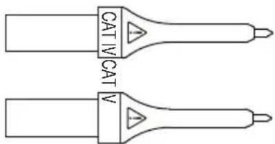
Test probes ∅ 2 x 15 mm (one red and one black)
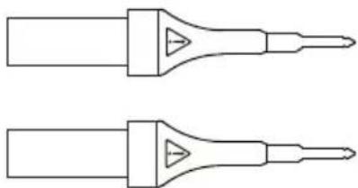
Test probes ∅ 4 x 15 mm (one red and one black)
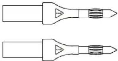
Red IP2X test probe ∅ 2 mm (one red and one black)
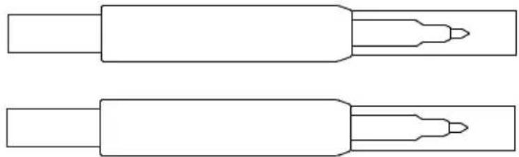
Red IP2X test probe ∅ 4 mm (one red and one black)
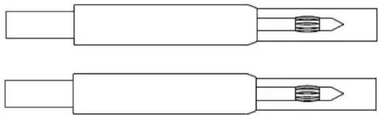
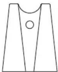
Cap
1.2. OPTIONS
Carrying case
For accessories and spare parts, visit our website: www.chauvin-arnoux.com
2. INTRODUCTION
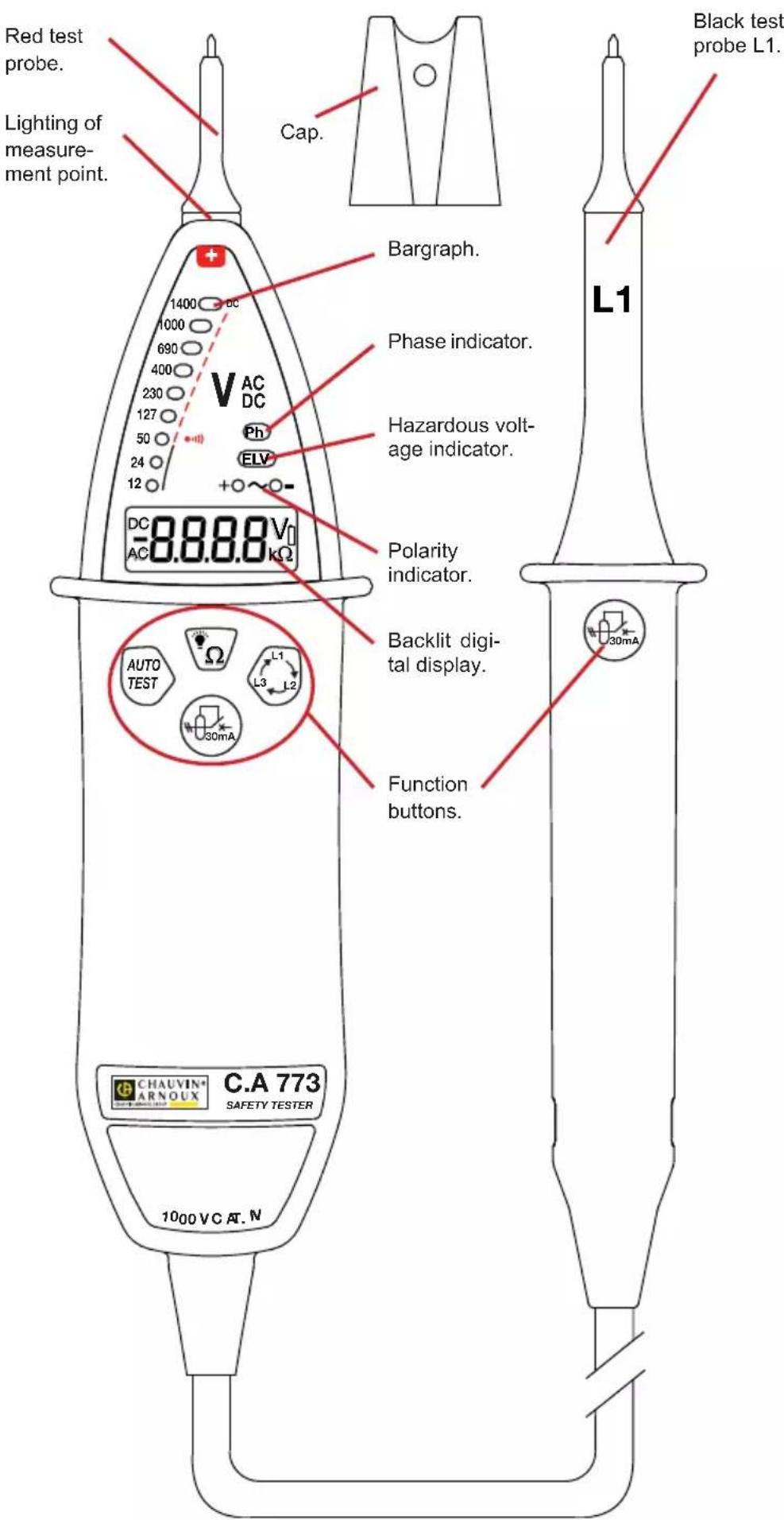
2.1.C.A 773
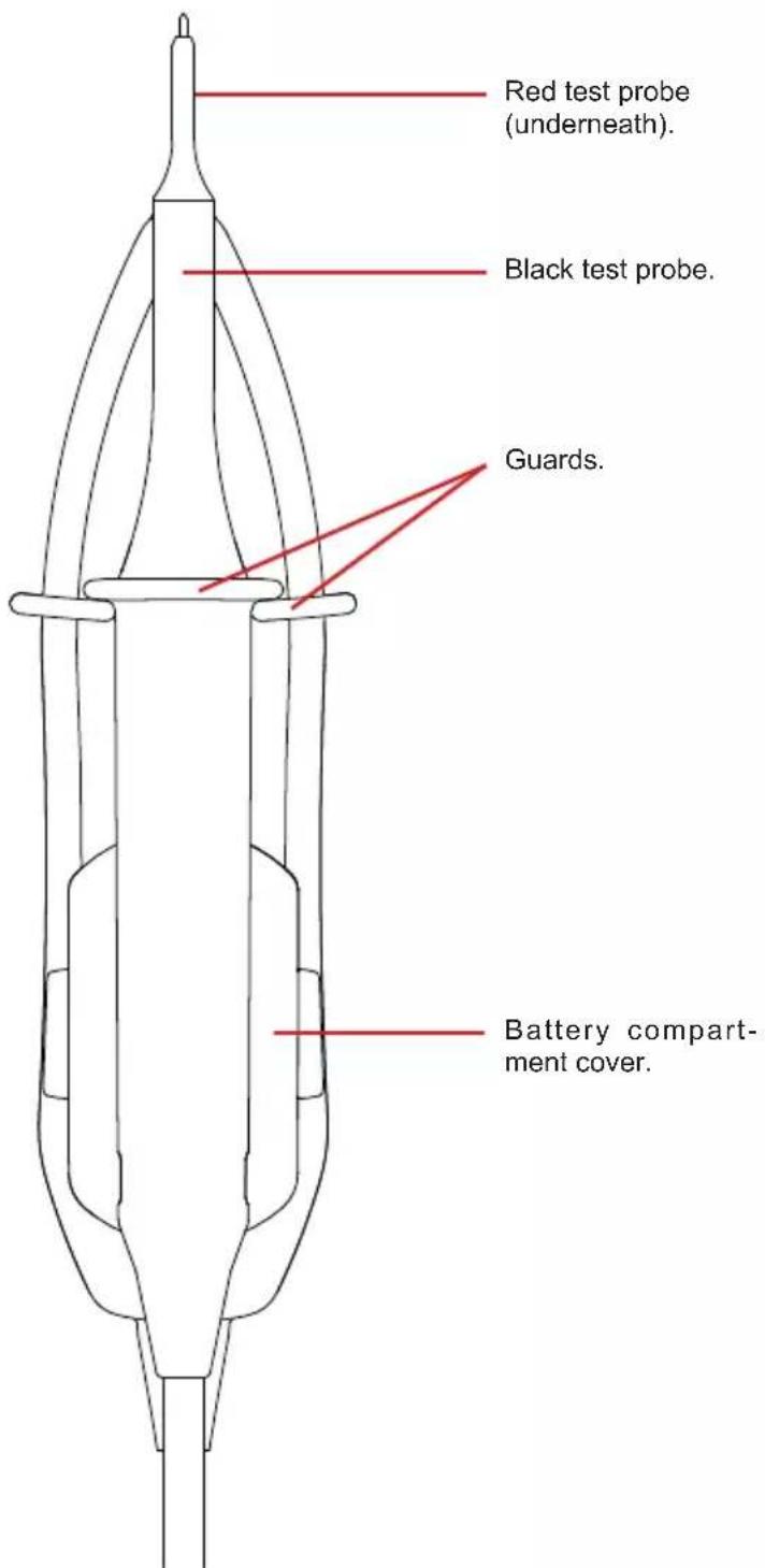
2.2. ON THE BACK
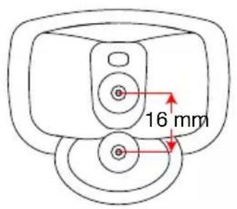
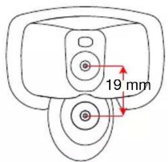
There are two ways to attach the black test probe to the back:
■ flat, with a 16 mm distance between test probes,
■ on the side, with a 19 mm distance between test probes.
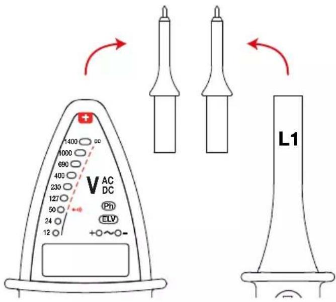
2.3. TEST PROBES
The tips of the test probes are removable.
2.4. C.A 773 IP2X
See § 3.8.
2.5. FUNCTIONALITY
The C.A 773 is a voltage detector with indicator lights.
It complies with the recommendations of the IEC 61243-3 standard.
The main function of the C.A 773 is Voltage Absence Testing (VAT). It detects hazardous voltages, i.e. higher than ELV (extra-low voltage) 50VAC or 120VDC ), even if the device's batteries are spent or absent.
Its other functions are:
■ Indicating a voltage between 12 and 1000 VAC or 1400 VDC with polarity indication.
■ Indicating the quality of the continuity level.
■ Indicating the phase position.
■ Indicating the phase order.
■ Load switching (controlling the triggering of the 30 mA differential circuit breakers).
The voltages indicated on the C.A 773 are nominal voltages. Ensure that it is used on voltage-normalized networks.
3. USE
This device is a detector. The indications it provides must not be used for measurement purposes.
3.1. SELF-TEST
Before using the C.A 773, run a self-test. This checks the integrity of the cable and the test probes, correct operation of the electronic circuit, and a sufficient voltage level for the batteries.
Connect the red test probe to the + terminal and the black test probe to the L1 terminal.
Bring the two test probes into contact and press the AUTO TEST button. Hold it down as long as necessary.
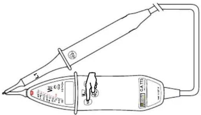
If all indicators on the device except ELV light up, the buzzer sounds and the digital display indicates "ready", the device is operating properly and is usable.
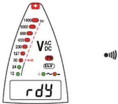
■ If every second indicator lights up along with the symbol, the batteries must be replaced (see § 5.2).
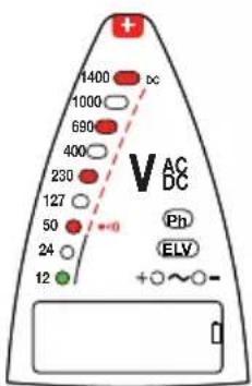
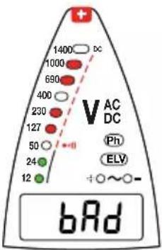
If every third indicator lights up and the display indicates "bad", there is a problem with the test probes. Check that they are connected correctly and are in contact, and then press the AUTO TEST button again. If the problem persists, the test probes must be replaced. If the problem still persists, the device must no longer be used.
If no indicators light up, replace the batteries (see § 5.2). If the problem persists with new batteries, the device is defective and must be sent for repair.
Repeat the self-test after each measurement to confirm that the device is operating properly.
In a noisy atmosphere, ensure that you are able to hear the buzzer.
Note: If the AUTO TEST button is held down for more than 10 seconds with the test probes not in contact, the device goes into stand-by mode.
3.2. LIGHTING OF MEASUREMENT POINT
The C.A 773 can light up the measurement point, with a white indicator light located under the red test probe.
To switch this light on, press the Ω button.
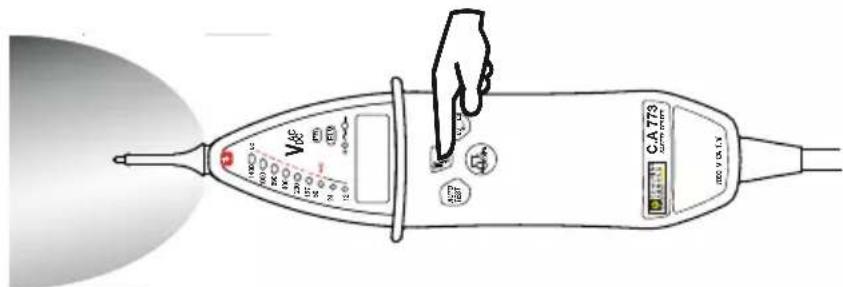
To switch the light off, press the Ω button again, or wait for it to extinguish itself automatically after about 10 seconds.
3.3. VOLTAGE DETECTION
Connect the red test probe to the + terminal and the black test probe to the L1 terminal.
Place your hands behind the guards on the device and the test probe.
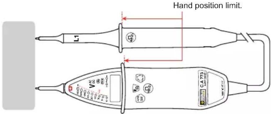
Place the test probes on the element to be tested, and hold them firmly in contact.
There is no need to switch on the C.A 773; it starts up automatically. The voltage is displayed on the bargraph and on the digital display unit.
If the voltage present is:
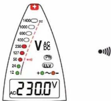
■ AC: the indicators light up to indicate its value, and the + (green) and - (orange) indicators are lit.
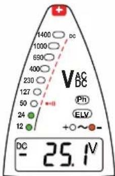
■ DC: the indicators light up to indicate its value, and the + (green) indicator or the - (orange) indicator lights up to indicate the polarity.
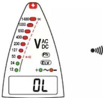
■ hazardous (> 50 VAC or 120 VDC): the ELV (red) indicator flashes (the faster the flashing, the higher the voltage), and the device beeps.
ELV: Extra Low Voltage. This redundant indicator light indicates that the voltage is above ELV.
The first two indicators on the bargraph are green to indicate that the voltage is not hazardous, and the device does not beep. The next ones are red, and the device beeps.
If the voltage exceeds 1000 VAC or 1400 VDC, the digital display indicates "overload". The bargraph and the audible signal remain active.
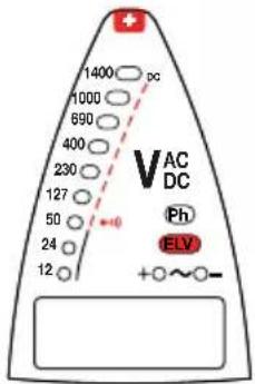
If only the ELV indicator lights up, the batteries are spent or absent.
3.4. INDICATING THE QUALITY OF THE CONTINUITY LEVEL.
As for voltage detection, connect the red test probe to the + terminal and the black test probe to the L1 terminal.
Place your hands behind the guards on the device and the test probe.
Place the test probes on the element to be tested, and hold them firmly in contact.
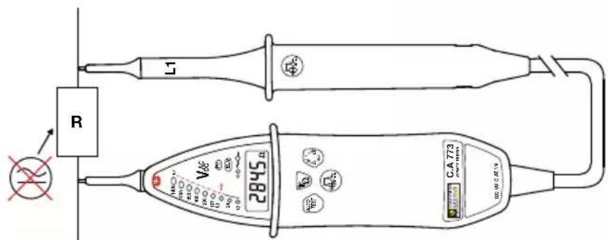
If the device has been idle for more than 10 minutes or if it was set to stand-by mode, run a self-test first, to place it in active stand-by.
Keep the Ω button pressed.
If no voltage is detected, the C.A 773 performs a continuity check.
The result is indicated only on the digital display.
If it is less than 125 Ω, the device emits a continuous audible signal.
3.5. PHASE DETECTION
The C.A 773 performs single-pole phase detection.. This means that you can connect just one test probe to find out if a phase is present.
Warning: Phase detection cannot replace an absence of voltage test.
To operate properly, phase detection must be used on earth-referenced networks.
This means, for example, that you can locate the phase on a connector for an earth-referenced network.
Connect the black test probe to terminal L1.
Place your hands behind the guard on the device.
Place the test probe on the element to be tested, and hold it firmly in contact.
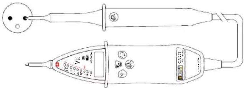
If the test probe is on the phase, the Ph (phase) indicator flashes and the device beeps.
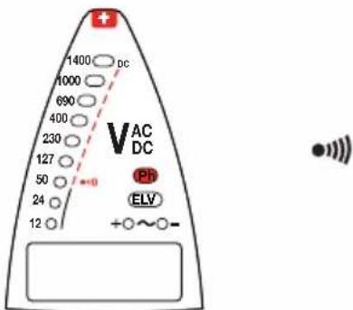
Note: The fact that the Ph indicator is not flashing does not mean that there is not a hazardous voltage on the connector.
3.6. ORDER OF PHASES
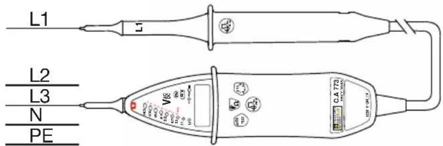
Place the black test probe on the first phase of the three-phase system and the red test probe on the second phase. The device indicates the voltage that is present.
Press the button.
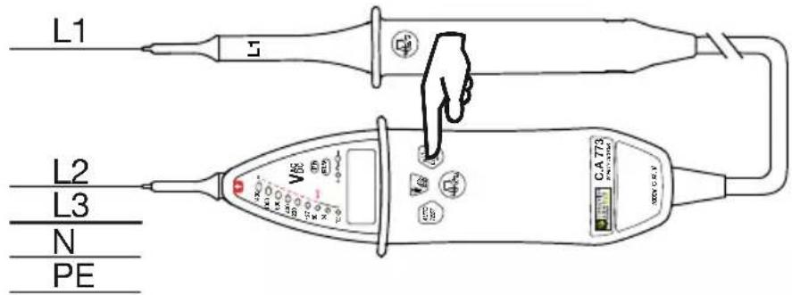
■ If the voltage is less than 50 VAC or DC, it cannot be measured.
- Otherwise, the device reports that it is taking the voltage reference by the blinking of “reference” on the display unit.
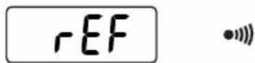
When the reference has been acquired, the C.A 773 emits two treble beeps and "reference" is displayed steadily.
Then shift the red probe tip to the last phase of the system.
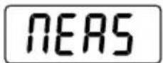
The device displays "measurement" to indicate that it is making the measurement.
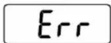
If there is a problem, i.e. if the device does not detect a phase change within 10 seconds or if the phases are not balanced, it indicates an error by emitting two low-pitched beeps and displaying "error".
Otherwise, the device indicates the phase order by lighting up:
■ L123 and emitting a low-pitched beep followed by a treble beep,
■ or L132 and emitting a treble beep followed by a low-pitched beep

3.7. LOAD SWITCHING
During voltage detection, if there is an interference voltage near the element being tested, the device may indicate the presence of an operating voltage when in fact there is none.
If this voltage is < 400 V, press the two buttons to distinguish an interference voltage from an operating voltage. If it is an interference voltage, the voltage indication disappears while the buttons are being pressed.
On systems equipped with 30 mA differential circuit breakers, they can be triggered by pressing these two buttons.
Place the + test probe on the phase, and the black test probe on the protection conductor, where these two conductors belong to the circuit protected by the differential circuit breaker to be tested.
A voltage indication appears on the bargraph and on the digital display.
Press the two buttons together (the one on the device and the one on the test probe).
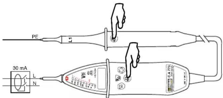
If the voltage measured is between 8 Vrms and 400 Vrms, the test is triggered.
If the voltage is 230 Vrms, the 30 mA differential circuit breaker is triggered and the voltage disappears from the bargraph and from the digital display.
This test generates a high current that heats the device. When it is too hot, you must wait for it to cool before resuming the use of this function.
3.8. IP2X TEST PROBES
IP2X test probe leads are delivered with the device (C.A 773 IP2X) or as an option (C.A 773) according to the model ordered.
The use of IP2X accessories is an additional safety feature. These accessories may be mandatory in certain countries.
In France, their use is imposed by standards (NF C 18-510, UTE C 18-510) and government decrees.
Connect the red IP2X test probe to the + terminal and the black IP2X test probe to the L1 terminal.

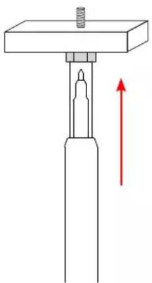
To perform a test, place the test probe on the object to be tested and press to slide the protective cover.
4.1. REFERENCE CONDITIONS
| Influence quantity Reference values | |
| Temperature 23 ± 5°C | |
| Relative humidity 30 to 75% RH | |
| Power supply voltage 3 ± 0.1 V | |
| Frequency of the measured signal | DC or 45 to 65 Hz |
| Type of signal sinusoidal | |
| External electrical field < 1 V/m | |
| External DC magnetic field < 40 A/m | |
4.2. ELECTRICAL CHARACTERISTICS
4.2.1. VOLTAGE
Nominal voltages: 12, 24, 50, 127, 230, 400, 690, 1000 VAC/ VDC and 1400 VDC.
Intrinsic uncertainty: ± (3% + 5 ct)
Resolution: 0,1 V from 1 to 299,9 V
1 V from de 300 V
Operating frequency: DC and 16.67 to 800 Hz
Maximum input current: 3.5 mArms.
Internal impedance at 50 VAC: 1100 kΩ. / 6,5 kΩ if load switching.
Response time < 500 ms.
Response time of ELV indicator < 1 s.
The indicator corresponding to voltage V lights up before the voltage reaches 85%V.
If the voltage present is < 12 V, no indicator is lit.
If the voltage present is < 1 V, the digital display is off.
The C.A 773 must be used on voltage-normalized networks only.
Operating cycle: 30 s (maximum time that the device can be connected to a live element) - 240 s (minimum rest time during which the detector must not be connected to a live element).
4.2.2. CONTINUITY
Continuity detection is inhibited if a voltage > 1 V is present.
Measurement range: 0 to 3 kΩ
Intrinsic uncertainty: ± (3% + 5 ct)
Resolution: 0,1 Ω from 1 to 299,9 Ω
0,001 kΩ from 0,3 to 3 kΩ
Audible signal triggering threshold: 100 Ω -0% +50%
Test current ≤ 1 mA
Open circuit voltage ≤ 5 V
4.2.3. PHASE IDENTIFICATION
15 Hz < frequency < 65 Hz
50 VAC < voltage < 1000 VAC for 45 Hz < frequency ≤ 65 Hz
150 VAC < voltage < 1000 VAC for frequency < 45 Hz
4.2.4. ORDER OF PHASES
Phase between 45 and 400 Hz.
Voltage between 50 and 1000 VAC between phases.
Time for acquisition of information after contact ≤ 1 s.
Information retention time: 10 s.
Allowable unbalance amplitude: 20%.
Allowable voltage harmonics: 10%.
Rejection of EDF remote control frames (TCC-175 Hz-188 Hz).
4.2.5. LOAD SWITCHING
Switched load: approximately 6,5 kΩ at 50 VAC.
Peak current: 90 mA.
Current consumed at 230 VAC: 30 mA.
Triggering between 8 and 400 VAC.
Overload protection after 10 seconds at 230 V and 2 seconds at 400 V.
4.3. ENVIRONMENTAL CONDITIONS
This is a Type S device. It must be used under the following conditions:
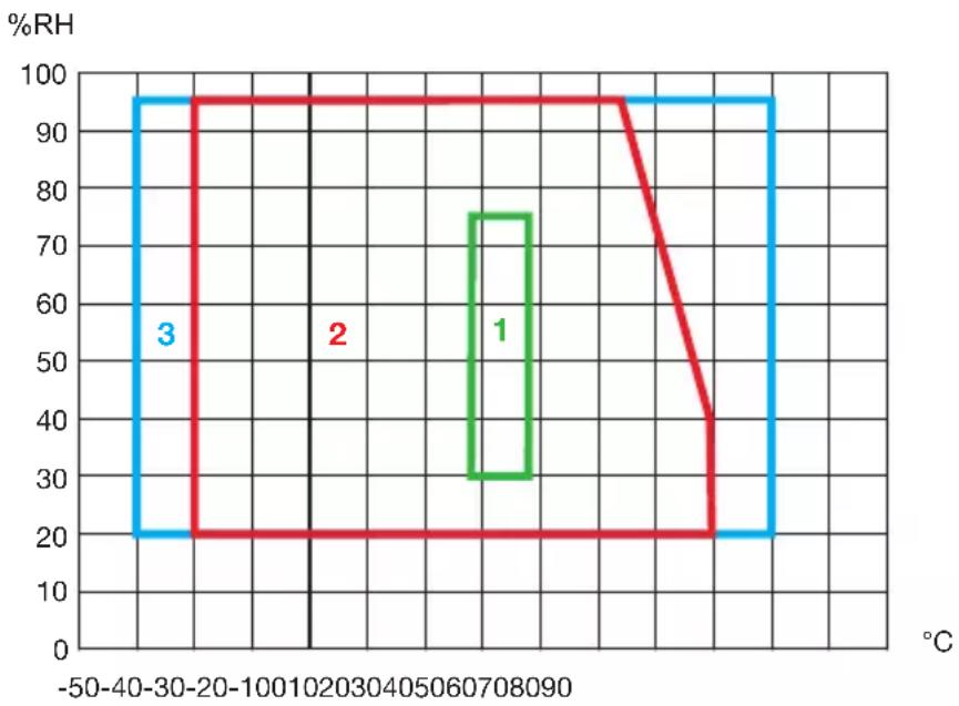
1: Reference range
2: Operating range
-15 à +45°C and 20 to 95% RH excluding condensation.
3: Storage range (without battery)
-40 to +70°C and 20 to 95% RH excluding condensation.
Before leaving the device idle for an extended period or before storage, remove the batteries from the housing.
The device must be stored in a clean, dry location.
Use indoors or outdoors if not raining.
Degree of pollution: 2.
Altitude: < 2000 m.
4.4. POWER SUPPLY
The C.A 773 is powered by two 1.5 V alkaline batteries (type AA or LR6).
The battery life provides 2,500 ten-second measurements.
The batteries can be replaced with rechargeable accumulators, but these will not last as long.
4.5. BUILD CHARACTERISTICS
Dimensions (L x W x D)
■ of the device 228 x 60 x 39 mm
■ of the test probe 218 x 35 x 25 mm
Mass 350 g approx.
Cable length 1 m
Protection rating
■ IP 65 according to IEC 60529
■ IK 06 - 1J - Eha pendulum hammer method according to IEC 50102
Drop test 2 meters.
4.6. COMPLIANCE WITH INTERNATIONAL STANDARDS
Two-pole voltage detector EN 61243-3 Ed. 3 dated 2015.
The device is in conformity with IEC-61010-1 1000V, CAT IV.
4.7. ELECTROMAGNETIC COMPATIBILITY
Emission and immunity in industrial environment according to IEC 61326-1.
5. MAINTENANCE

Except for the batteries, the instrument contains no parts that can be ced by personnel who have not been specially trained and accredited.
Any unauthorized repair or replacement of a part by an “equivalent” may gravely impair safety.
5.1. CLEANING
The device must be kept perfectly clean.
Disconnect the instrument completely.
Use a soft cloth, dampened with soapy water. Rinse with a damp cloth and dry rapidly with a dry cloth or forced air. Do not use alcohol, solvents, or hydrocarbons.
5.2. REPLACEMENT OF BATTERIES
Any handling of the battery compartment cover must take place on a clean device and in a clean environment.
If, during the self-test, the symbol is displayed, you must replace the batteries.
■ Disconnect anything connected to the device.
■ Using a screwdriver, unscrew the two captive screws of the battery compartment cover located on the back of the device.
■ Withdraw the spent batteries and replace them with two new batteries (AA or LR6 1.5V alkaline batteries).
■ Close the battery compartment cover and make sure that it is completely and correctly closed.
■ Screw the two screws back in.

Spent batteries must not be treated as ordinary household waste. Take them to the appropriate recycling collection point.
6. WARRANTY
Except as otherwise stated, our warranty is valid for 24 months starting from the date on which the equipment was sold. Extract from our General Conditions of Sale provided on request.
The warranty does not apply in the following cases:
■ Inappropriate use of the equipment or use with incompatible equipment;
■ Modifications made to the equipment without the explicit permission of the manufacturer's technical staff;
■ Work done on the device by a person not approved by the manufacturer;
■ Adaptation to a particular application not anticipated in the definition of the equipment or not indicated in the user's manual;
■ Damage caused by shocks, falls, or floods.
Schutzkappe
1.2. OPTIONEN
Transporttasche
3.7. LASTSCHALTUNG
Cappuccio
1.2. OPZIONI
3.7. COMMUTAZIONE DELLE CARICHE
Dimensioni (L x l x P)
Tapa
1.2. OPCIONES
Funda de transporte
Our international contacts
www.chauvin-arnoux.com/contacts

CHAUVIN®
ARNOUX
CHALVIN ARNOUX GROUP


- C.A 773 C.A 773 IP2X
- OPTIONS
- DEFINITION OF MEASUREMENT CATEGORIES
- CONTENTS
- SAFETY ADVICES
- DELIVERY CONDITION
- VOLTAGE DETECTOR C.A 773
- DELIVERED WITH
- VOLTAGE DETECTOR C.A 773 IP2X
- ACCESSORIES AND SPARE PARTS
- INTRODUCTION
- ON THE BACK
- TEST PROBES
- C.A 773 IP2X
- FUNCTIONALITY
- USE
- SELF-TEST
- LIGHTING OF MEASUREMENT POINT
- VOLTAGE DETECTION
- INDICATING THE QUALITY OF THE CONTINUITY LEVEL
- PHASE DETECTION
- ORDER OF PHASES
- LOAD SWITCHING
- IP2X TEST PROBES
- REFERENCE CONDITIONS
- ELECTRICAL CHARACTERISTICS
- VOLTAGE
- CONTINUITY
- PHASE IDENTIFICATION
- ENVIRONMENTAL CONDITIONS
- POWER SUPPLY
- BUILD CHARACTERISTICS
- COMPLIANCE WITH INTERNATIONAL STANDARDS
- ELECTROMAGNETIC COMPATIBILITY
- MAINTENANCE
- CLEANING
- REPLACEMENT OF BATTERIES
- WARRANTY
- OPTIONEN
- LASTSCHALTUNG
- OPZIONI
- COMMUTAZIONE DELLE CARICHE
- OPCIONES
- OUR INTERNATIONAL CONTACTS
Brand : CHAUVIN ARNOUX
Model : C.A 773
Category : Measuring equipment