
MultiSync LCD1980SX - Monitor NEC - Free user manual and instructions
Find the device manual for free MultiSync LCD1980SX NEC in PDF.
| Product Type | 19-inch LCD Monitor |
| Brand | NEC |
| Model | MultiSync LCD1980SX |
| Native Resolution | 1280 x 1024 |
| Screen Size | 19 inches (diagonal) |
| Panel Type | LCD TFT |
| Aspect Ratio | 5:4 |
| Brightness | 250 cd/m² (typical) |
| Contrast Ratio | 500:1 (typical) |
| Response Time | 16 ms (typical) |
| Connectivity | DVI-D (digital), DVI-A (analog), VGA input via adapter |
| Power Supply | 220-240 V AC, 50/60 Hz |
| Power Consumption | 38 W (typical) |
| Dimensions (with stand) | 412 x 430 x 250 mm (W x H x D) (approx.) |
| Weight | 8.5 kg (approx.) |
| Ergonomics | Tilt, swivel, rotation (landscape/portrait), height adjustable |
| OSM Functions | Brightness, Contrast, Auto Adjust, Position, Width, Fine, Colors, Languages, Lock, OSM Rotation, etc. |
| Compliance | ENERGY STAR, CE, EN 60950, EN 55022, EN 61000-3-2, EN 61000-3-3, EN 55024 |
| Supplied Accessories | Power cable, DVI-D video cable, DVI-A video cable, CD-ROM, cable cover |
| Maintenance | Soft lint-free cloth; do not use solvents or glass cleaners |
| Safety | Do not open the housing; do not expose to water; unplug if damaged |
Frequently Asked Questions - MultiSync LCD1980SX NEC
User questions about MultiSync LCD1980SX NEC
0 question about this device. Answer the ones you know or ask your own.
Ask a new question about this device
Download the instructions for your Monitor in PDF format for free! Find your manual MultiSync LCD1980SX - NEC and take your electronic device back in hand. On this page are published all the documents necessary for the use of your device. MultiSync LCD1980SX by NEC.
USER MANUAL MultiSync LCD1980SX NEC
Canadian Department of Communications Compliance Statement
DOC: This Class B digital apparatus meets all requirements of the Canadian Interference-Causing Equipment Regulations.
C-UL: Bears the C-UL Mark and is in compliance with Canadian Safety Regulations according to CAN/CSA C22.2 No. 60950.
FCC Information
- Use the attached specified cables with the MultiSync LCD1980SX colour monitor so as not to interfere with radio and television reception.
(1) The power supply cord you use must have been approved by and comply with the safety standards of U.S.A., and meet the following condition.
| Power supply cord Non Length 2.0 m Plug shape | shield type, 3-conductor U.S.A |
(2) Please use the supplied shielded video signal cable, 15-pin mini D-SUB to DVI-A cable or DVI-D to DVI-D cable. Use of other cables and adapters may cause interference with radio and television reception.
-
This equipment has been tested and found to comply with the limits for a Class B digital device, pursuant to part 15 of the FCC Rules. These limits are designed to provide reasonable protection against harmful interference in a residential installation. This equipment generates, uses, and can radiate radio frequency energy, and, if not installed and used in accordance with the instructions, may cause harmful interference to radio communications. However, there is no guarantee that interference will not occur in a particular installation. If this equipment does cause harmful interference to radio or television reception, which can be determined by turning the equipment off and on, the user is encouraged to try to correct the interference by one or more of the following measures:
-
Reorient or relocate the receiving antenna.
- Increase the separation between the equipment and receiver.
- Connect the equipment into an outlet on a circuit different from that to which the receiver is connected.
- Consult your dealer or an experienced radio/TV technician for help.
If necessary, the user should contact the dealer or an experienced radio/television technician for additional suggestions. The user may find the following booklet, prepared by the Federal Communications Commission, helpful: "How to Identify and Resolve Radio-TV Interference Problems." This booklet is available from the U.S. Government Printing Office, Washington, D.C., 20402, Stock No. 004-000-00345-4.
Declaration of Conformity
This device complies with Part 15 of FCC Rules. Operation is subject to the following two conditions. (1) This device may not cause harmful interference, and (2) this device must accept any interference received, including interference that may cause undesired operation.
U.S. Responsible Party: NEC-Mitsubishi Electronics Display of America, Inc.
Address: 1250 North Arlington Heights Road, Suite 500
Itasca, Illinois 60143-1248
Tel. No.: (630) 467-3000
Type of Product: Display Monitor
Equipment Classification: Class B Peripheral
Model: MultiSync LCD1980SX (L192G3)

We hereby declare that the equipment specified above conforms to the technical standards as specified in the FCC Rules.
TCO'99 (Black model)
Congratulations! You have just purchased a TCO'99 approved and labeled product! Your choice has provided you with a product developed for professional use. Your purchase has also contributed to reducing the burden on the environment and also to the further development of environmentally adapted electronics products.

Why do we have environmentally labelled computers?
In many countries, environmental labelling has become an established method for encouraging the adaptation of goods and services to the environment. The main problem, as far as computers and other electronics equipment are concerned, is that environmentally harmful substances are used both in the products and during the manufacturing. Since it has not been possible for the majority of electronics equipment to be recycled in a satisfactory way, most of these potentially damaging substances sooner or later enter Nature.
There are also other characteristics of a computer, such as energy consumption levels, that are important from the viewpoints of both the work (Internal) and natural (external) environments. Since all methods of conventional electricity generation have a negative effect on the environment (acidic and climate-influencing emissions, radioactive waste, etc.), it is vital to conserve energy. Electronics equipment in offices consume an enormous amount of energy since they are often left running continuously.
What does labelling involve?
This product meets the requirements for the TCO'99 scheme which provides for international and environmental labelling of personal computers. The labelling scheme was developed as a joint effort by the TCO (The Swedish Confederation of Professional Employees), Svenska Naturskyddsforeningen (The Swedish Society for Nature Conservation) and Statens Energimyndighet (The Swedish National Energy Administration).
The requirements cover a wide range of issues: environment, ergonomics, usability, emission of electrical and magnetic fields, energy consumption and electrical and fire safety.
The environmental demands concern restrictions on the presence and use of heavy metals, brominated and chlorinated flame retardants, CFCs (freons) and chlorinated solvents, among other things. The product must be prepared for recycling and the manufacturer is obliged to have an environmental plan which must be adhered to in each country where the company implements its operational policy. The energy requirements include a demand that the computer and/or display, after a certain period of inactivity, shall reduce its power consumption to a lower level in one or more stages. The length of time to reactivate the computer shall be reasonable for the user.
Labelled products must meet strict environmental demands, for example, in respect of the reduction of electric and magnetic fields, physical and visual ergonomics and good usability.
Environmental Requirements
Flame retardants
Flame retardants are present in printed circuit boards, cables, wires, casings and housings. In turn, they delay the spread of fire. Up to thirty percent of the plastic in a computer casing can consist of flame retardant substances. Most flame retardants contain bromine or chloride and these are related to another group of environmental toxins, PCBs, which are suspected to give rise to severe health effects, including reproductive damage in fisheating birds and mammals, due to the bioaccumulative* processes. Flame retardants have been found in human blood and researchers fear that disturbances in foetus development may occur.
TCO'99 demand requires that plastic components weighing more than 25 grams must not contain flame retardants with organically bound chlorine and bromine. Flame retardants are allowed in the printed circuit boards since no substitutes are available.
Lead\*\*
Lead can be found in picture tubes, display screens, solders and capacitors. Lead damages the nervous system and in higher doses, causes lead poisoning.
TCO'99 requirement permits the inclusion of lead since no replacement has yet been developed.
Cadmium\*\*
Cadmium is present in rechargeable batteries and in the colour generating layers of certain computer displays. Cadmium damages the nervous system and is toxic in high doses.
TCO'99 requirement states that batteries, the colourgenerating layers of display screens and the electrical or electronics components must not contain any cadmium.
Mercury\*\*
Mercury is sometimes found in batteries, relays and switches, Mercury damages the nervous system and is toxic in high doses.
TCO'99 requirement states that batteries may not contain any Mercury. It also demands that no mercury is present in any of the electrical or electronics components associated with the display unit.
CFCs (freons)
CFCs (freons) are sometimes used for washing printed circuit boards. CFCs break down ozone and thereby damage the ozone layer in the stratosphere, causing increased reception on Earth of ultraviolet light with consequent increased risks of skin cancer (malignant melanoma).
The relevant TCO'99 requirement; Neither CFCs nor HCFCs may be used during the manufacturing and assembly of the product or its packaging.
*Bio-accumulative is defined as substances which accumulate within living organisms.
**Lead, Cadmium and Mercury are heavy metals which are Bio-accumulative.
To obtain complete information on the environmental criteria document, order from:
TCO Development Unit
SE-114 94 Stockholm
SWEDEN
FAX Number: +46 8 782 92 07
E-mail (Internet): development@tco.se
You may also obtain current information on TCO'99 approved and labelled products by visiting their website at:
http://www.tcodevelopment.com
TCO'03 (White model)
TcODevelopment

Congratulations!
The display you have just purchased carries the TCO'03 Displays label. This means that your display is designed, manufactured and tested according to some of the strictest quality and environmental requirements in the world. This makes for a high performance product, designed with the user in focus that also minimizes the impact on our natural environment.
Some of the features of the TCO'03 Display requirements:
Ergonomics
- Good visual ergonomics and image quality in order to improve the working environment for the user and to reduce sight and strain problems. Important parameters are luminance, contrast, resolution, reflectance, colour rendition and image stability.
Energy
- Energy-saving mode after a certain time – beneficial both for the user and the environment
- Electrical safety
Emissions
- Electromagnetic fields
- Noise emissions
Ecology
- The product must be prepared for recycling and the manufacturer must have a certified environmental management system such as EMAS or ISO 14 000
- Restrictions on: - chlorinated and brominated flame retardants and polymers - heavy metals such as cadmium, mercury and lead.
The requirements included in this label have been developed by TCO Development in co-operation with scientists, experts, users as well as manufacturers all over the world. Since the end of the 1980s TCO has been involved in influencing the development of IT equipment in a more user-friendly direction. Our labelling system started with displays in 1992 and is now requested by users and IT-manufacturers all over the world.
For more information, please visit
www.tcodevelopment.com
Manufacturer's Recycling and Energy Information
NEC-Mitsubishi Electric Visual Systems Corp. is strongly committed to environmental protection and sees recycling as one of the company's top priorities in trying to minimize the burden placed on the environment. We are engaged in developing environmentally-friendly products, and always strive to help define and comply with the latest independent standards from agencies such as ISO (International Organisation for Standardization) and TCO (Swedish Trades Union).
For more information, and for help in recycling your old NEC or Mitsubishi monitors, please visit our website at
http://www.nec-mitsubishi.com (in Europe) or
http://www.nmv.co.jp/environment (in Japan) or
http://www.necmitsubishi.com/markets-solutions/totaltrade (in USA).
Country-specific recycling programmes can also be found at:
Sweden - http://www.el-retur.se
Germany - http://www.recyclingpartner.de/
This monitor features an advanced energy saving capability. When a VESA Display Power Management Signaling (DPMS) Standard signal is sent to the monitor, the Energy Saving mode is activated. The monitor enters a single Energy Saving mode.
| Mode Power consumption LED color | ||
| Normal Operation Approx. 36W Green | ||
| Energy Saving Mode Approx. 1W Amber | ||
| Off Mode Less than 0.1W Unlit | ||
Index
Warning, Caution ...... English-1
Declaration ...... English-1
Contents ...... English-2
Quick Start ...... English-3
Controls ...... English-6
Recommended Use ...... English-9
TO PREVENT FIRE OR SHOCK HAZARDS, DO NOT EXPOSE THIS UNIT TO RAIN OR MOISTURE. ALSO, DO NOT USE THIS UNIT'S POLARIZED PLUG WITH AN EXTENSION CORD RECEPTACLE OR OTHER OUTLETS UNLESS THE PRONGS CAN BE FULLY INSERTED.
REFRAIN FROM OPENING THE CABINET AS THERE ARE HIGH VOLTAGE COMPONENTS INSIDE. REFER SERVICING TO QUALIFIED SERVICE PERSONNEL.

CAUTION

CAUTION: TO REDUCE THE RISK OF ELECTRIC SHOCK, MAKE SURE POWER CORD IS UNPLUGGED FROM WALL SOCKET. TO FULLY DISENGAGE THE POWER TO THE UNIT, PLEASE DISCONNECT THE POWER CORD FROM THE AC OUTLET.DO NOT REMOVE COVER (OR BACK). NO USER SERVICEABLE PARTS INSIDE. REFER SERVICING TO QUALIFIED SERVICE PERSONNEL.

This symbol warns user that uninsulated voltage within the unit may have sufficient magnitude to cause electric shock. Therefore, it is dangerous to make any kind of contact with any part inside this unit.

This symbol alerts the user that important literature concerning the operation and maintenance of this unit has been included. Therefore, it should be read carefully in order to avoid any problems.
Caution:
When operating the MultiSync LCD1980SX with a 220-240V AC power source in Europe, use the power cord provided with the monitor.
In the UK, a BS approved power cord with a moulded plug has a Black (five Amps) fuse installed for use with this equipment. If a power cord is not supplied with this equipment please contact your supplier.
When operating the MultiSync LCD1980SX with a 220-240V AC power source in Australia, use the power cord provided with the monitor. If a power cord is not supplied with this equipment please contact your supplier.
For all other cases, use a power cord that matches the AC voltage of the power outlet and has been approved by and complies with the safety standard of your particular country.
Declaration
Declaration of the Manufacturer
We hereby certify that the colour monitor
MultiSync LCD1980SX (L192G3) is in compliance with
Council Directive 73/23/EEC:
- EN 60950
Council Directive 89/336/EEC:
EN 55022
- EN 61000-3-2
- EN 61000-3-3
- EN 55024
and marked with

NEC-Mitsubishi Electric Visual
Systems Corporation
4-13-23, Shibaura,
Minato-Ku
Tokyo 108-0023, Japan

TÜV Rheinland Product Safety
ISO 13406-2

Windows is a registered trademark of Microsoft Corporation. NEC is a registered trademark of NEC Corporation. ENERGY STAR is a U.S. registered trademark. All other brands and product names are trademarks or registered trademarks of their respective owners.
As an ENERGY STAR® Partner, NEC-Mitsubishi Electronics Display of America has determined that this product meets the ENERGY STAR guidelines for energy efficiency. The ENERGY STAR emblem does not represent EPA endorsement of any product or service. OmniColor is a registered trademark of NEC-Mitsubishi Electronics Display Europe GmbH in the countries of EU and Switzerland.
ErgoDesign is a trademark of NEC-Mitsubishi Electronic Visual Systems Corporation in Austria, Benelux, Denmark, France, Germany, Italy, Norway, Spain, Sweden, U.K.
NaViSet is a trademark of NEC-Mitsubishi Electronics Display Europe GmbH in the countries of EU and Switzerland.
English-1
Contents
Your new NEC MultiSync LCD monitor box* should contain the following:
- MultiSync LCD1980SX monitor with tilt/swivel/pivot/height adjust stand
- Power Cord
• Video Signal Cable (15-pin mini D-SUB male to DVI-A)
• Video Signal Cable (DVI-D to DVI-D cable) - User's Manual
- Cable cover
- CD ROM (includes complete User's Manual in PDF format).
To see the User's Manual, Acrobat Reader 4.0 must be installed on your PC.
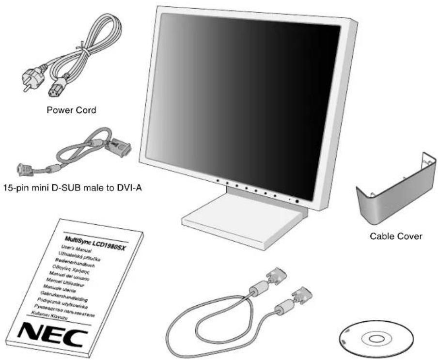
User's Manual DVI-D to DVI-D cable CD-ROM
* Remember to save your original box and packing material to transport or ship the monitor.
Quick Start
To attach the MultiSync LCD monitor to your system, follow these instructions:
-
Turn off the power to your computer.
-
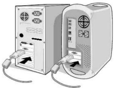
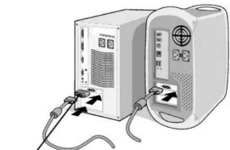
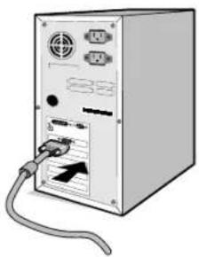
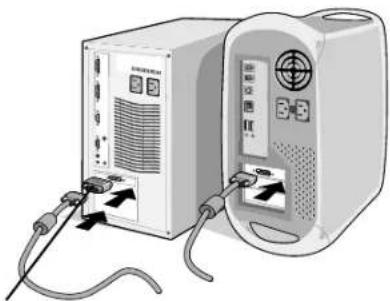
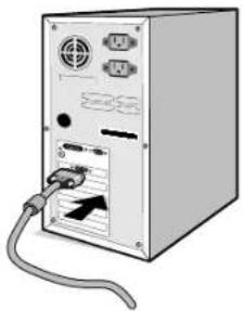
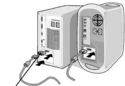
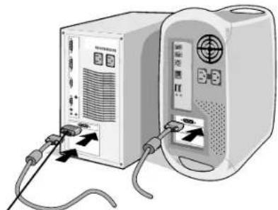
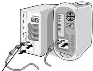
For the PC or MAC with DVI digital output: Connect the DVI signal cable to the connector of the display card in your system (Figure A.1). Tighten all screws.
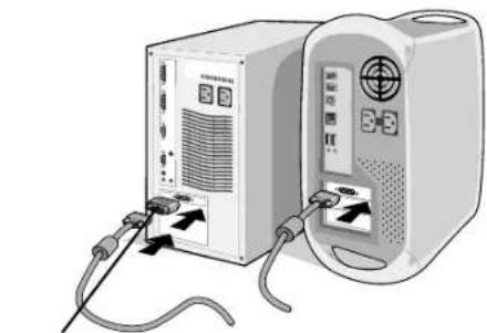
For the PC with Analog output: Connect the 15-pin mini D-SUB to DVI-A signal cable to the connector of the display card in your system (Figure A.2).
For the MAC: Connect the MultiSync Macintosh cable adapter to the computer, then attach the 15-pin mini D-SUB signal cable to the MultiSync Macintosh cable adapter (Figure B.1).
natural_image
Two computer units with attached cables and ports, no visible text or symbolsFigure A.1 Figure B.1

natural_image
Front view of a computer tower with attached cable and ports (no visible text or symbols)Figure A.2
natural_image
Illustration of two connected devices with cables and connectors, no visible text or symbolsMacintosh Cable Adapter (not included)
NOTE: Some Macintosh systems do not require a Macintosh cable adapter.
- Connect the DVI signal cable to the connector on the back of the monitor. Place the video signal cable (Figure C.1). Connect only either VGA or DVI to input 2.
NOTE: Incorrect cable connections may result in irregular operation, damage display quality/components of LCD module and/or shorten the module's life.
Collect cables and keep them in the stand with attached cable cover. The cable cover can be attached on the front or back side of Tilt Stand (Figure C.1, C.2).
Please check Tilt, Rise and Lower monitor screen and screen rotation when you manage cables.
- Connect one end of the power cord to the AC inlet on the back of the monitor and the other end to the power outlet (Figure C.1).
NOTE: Please refer to Caution section of this manual for proper selection of AC power cord.
- The Vacation Switch on the left side of the monitor must be turned on. Turn on the monitor with the front power button (Figure D.1).
NOTE: The Vacation Switch is a true on/off switch. If this switch is on the OFF position, the monitor cannot be turned on using the front button. DO NOT switch on/off quickly.
NOTE: For the MAC with digital output: Before turning on the MAC, the DVI Input mode must be set to DIGITAL in "DVI SELECTION" of OSM by pressing "SELECT" button then "CONTROL" button when the DVI signal cable is connected to the DVI-I connector (Input1) of the monitor. Otherwise the MAC may not turn on.
- Turn on the computer. No-touch Auto Adjust automatically adjusts the monitor to optimal settings upon initial setup for most timings. For further adjustments, use the following OSM controls:
• Auto Contrast (Analog input only)
• Auto Adjust (Analog input only)
Refer to the Controls section of this User's Manual for a full description of these OSM controls.
NOTE: If you have any problems, please refer to the Troubleshooting section of this User's Manual.
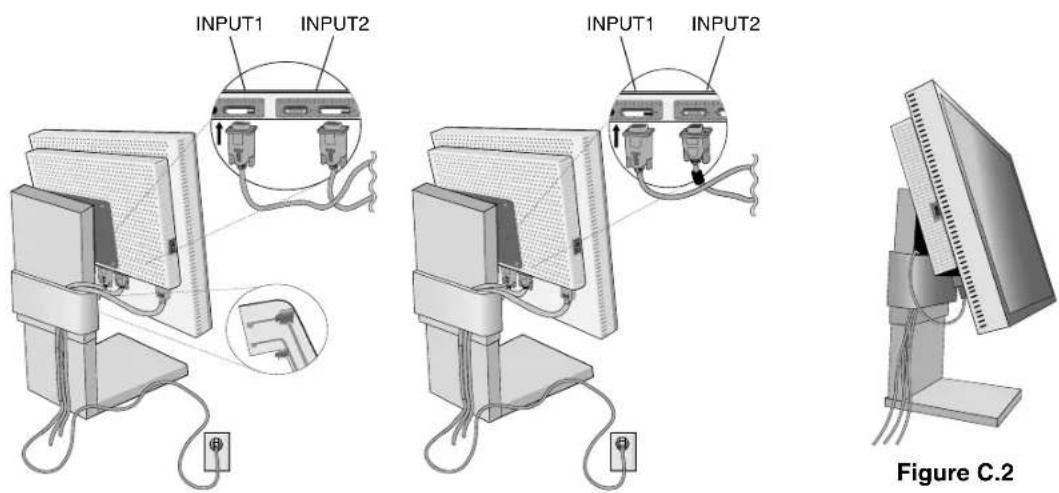
Figure C.1
natural_image
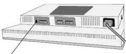
Illustration of a desktop computer tower with an open port and cable (no text or symbols visible)NEC-Mitsubishi optional product attachment. Do not use this connector unless specified.
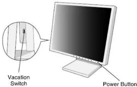
Figure D.1
Raise and Lower Monitor Screen
The monitor may be raised or lowered in either Portrait or Landscape mode.
To raise or lower screen, place hands on each side of the monitor and lift or lower to the desired height (Figure RL.1).
NOTE: Handle with care when raising or lowering the monitor screen.
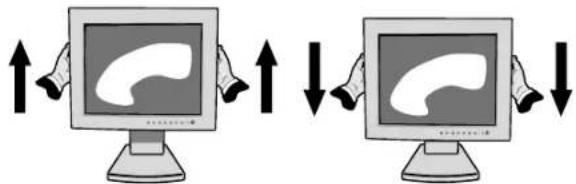
Figure RL.1
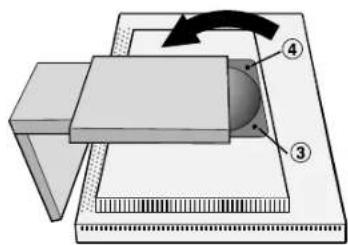
Screen Rotation
Before rotating, the screen must be raised to the highest level to avoid knocking the screen on the desk or pinching with your fingers.
To raise the screen, place hands on each side of the monitor and lift up to the highest position (Figure RL.1).
To rotate screen, place hands on each side of the monitor screen and turn clockwise from Landscape to Portrait or counterclockwise from Portrait to Landscape (Figure R.1).
To rotate OSM menu between landscape and portrait, refer to "Controls" section, "OSM ROTATION" function.
flowchart
graph TD
    A["Computer monitor with icon"] -->|Forward| B["Computer monitor with icon"]
    B -->|Reverse| A
Figure R.1
English-4
Tilt
Grasp top and bottom sides of the monitor screen with your hands and adjust the tilt as desired (Figure TS.1).

natural_image
Illustration of a hand holding a computer monitor with a curved screen and arrows indicating rotation (no text or symbols)Figure TS.1
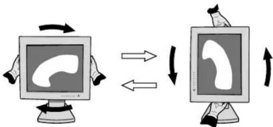
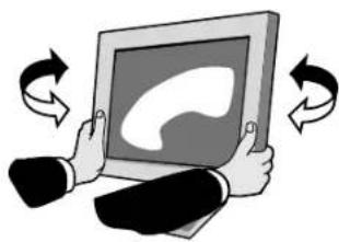
Swivel
Grasp both sides of the monitor screen with your hands and adjust the swivel as desired (Figure TS.2).

natural_image
Illustration of two hands holding a tablet with a speech bubble, surrounded by curved arrows indicating rotation (no text or symbols)Figure TS.2
NOTE: Handle with care when tilting the monitor screen.
Remove Monitor Stand for Mounting
To prepare the monitor for alternate mounting purposes:
- Disconnect all cables.
- Place hands on each side of the monitor and lift up to the highest position.
- Place monitor face down on a non-abrasive surface. (Place the screen on a 33 mm platform so that the stand is parallel with the surface) (Figure S.1).
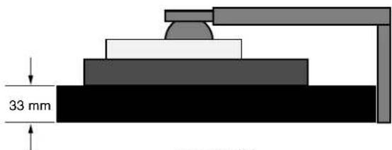
Figure S.1
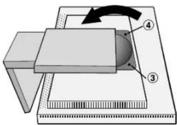
- Remove the two top screws connecting the monitor to the stand (Figure S.2). Turn the stand to 180° counterclockwise (you will hear two clicks). Remove the screws from the bottom (Figure S.3) and lift off the stand. The monitor is now ready for mounting in an alternate manner.
- Reverse this process to reattach stand: tighten the two bottom screws, turn stand 180° counter clockwise (you will hear two clicks), and tighten two top screws.
NOTE: Use only VESA-compatible alternative mounting method (100 mm pitch).
NOTE: Handle with care when removing monitor stand.
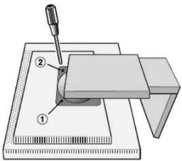
Figure S.2

Figure S.3
Caution: Use the original screws (4 pcs) when mounting to avoid damage to the monitor and stand. To fulfil the safety requirements the monitor must be mounted to an arm which guarantees the necessary stability under consideration of the weight of the monitor. The LCD monitor should only be used with an approved arm (e.g. GS mark).
English-5
Controls
OSM (On-Screen Manager) control buttons on the front of the monitor function as follows:
To access OSM menu, press any of the control buttons (EXIT, ◀, ▶, −, +). To change signal input, press the SELECT button.
NOTE: OSM must be closed in order to change signal input.
Menu
EXIT Exits the OSM controls.
Exits to the OSM main menu.
CONTROL ◀/▶ Moves the highlighted area left/right to select control menus.
Moves the highlighted area up/down to select one of the controls.
ADJUST - / + Moves the bar left/right or changes the adjustment value to increase or decrease the adjustment.
SELECT Activates the selected function. Enter the OSM controls. Enter the OSM sub menu. Select input while OSM disappeared.
RESET Resets the highlighted control menu to the factory setting.
NOTE: When RESET is pressed in the main and sub-menu, a warning window will appear allowing you to cancel the RESET function by pressing the EXIT button.
Brightness/Contrast Controls
BRIGHTNESS
Adjusts the overall image and background screen brightness.
CONTRAST
Adjusts the image brightness in relation to the background.
AUTO AUTO CONTRAST (Analog input only)
Adjusts the image displayed for non-standard video inputs.
AUTO BRT AUTO BRIGHTNESS
This function adjusts the brightness automatically for the best BRIGHTNESS setting based on the white display area.
AUTO Auto Adjust (Analog input only)
Automatically adjusts the Image Position and H. Size (or V. Size) settings and Fine settings.
Image Controls
LEFT / RIGHT
Controls Horizontal Image Position within the display area of the LCD.
DOWN / UP
Controls Vertical Image Position within the display area of the LCD.
H. SIZE (OSD ROTATION: Landscape) or V. SIZE (OSD ROTATION: Portrait) (Analog input only)
Adjusts the horizontal (or vertical) size by increasing or decreasing this setting.
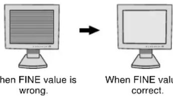
If the "Auto Adjust function" do not give you a satisfactory picture setting, a further tuning can be performed manually using the "H. Size (or V. Size)" function (dot clock). For this a Moiré test pattern could be used. This function may alter the width of the picture. Use Left/Right Menu to center the image on the screen. If the H. Size (or V. Size) is wrongly calibrated, the result would look like on the left drawing. The image should be homogeneous.
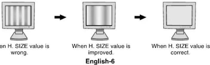
flowchart
graph LR
    A["When H. SIZE value is wrong."] --> B["When H. SIZE value is improved."]
    B --> C["When H. SIZE value is correct."]
|| FINE (Analog input only)
Improves focus, clarity and image stability by increasing or decreasing this setting.
If the "Auto Adjust function" do not give you a satisfactory picture setting, a fine tuning can be performed manually using the "Fine" function. It improves focus, clarity and image stability by increasing or decreasing this setting.
For this a Moiré test pattern could be used. If the Fine value is wrongly calibrated, the result would look like on the left drawing. The image should be homogeneous.
RGB Color Control Systems
Color Control Systems: Six colour presets select the desired colour setting (sRGB and NATIVE colour presets are standard and cannot be changed). Colour temperature increases or decreases, in each preset.
R,Y,G,C,B,M,S: Increases or decreases Red, Yellow, Green, Cyan, Blue, Magenta and Saturation depending upon which is selected. The change in colour will appear on screen and the direction (increase or decrease) will be shown by the colour bars.
NATIVE: Original colour presented by the LCD panel that is unadjustable.
Tools 1
a→a
SHARPNESS: This function is digitally capable to keep crisp image at any timings. It is continuously adjustable to get distinct image or soft one as you prefer, and set independently by different timings.

EXPANSION MODE: Sets the zoom method.
FULL: The image is expanded to 1280 x 1024, regardless of the resolution.
ASPECT: The image is expanded without changing the aspect ratio.
OFF: The image is not expanded.
CUSTOM1: Zoom with center fixed. The image is expanded from the rate of 1.0 to 3.0 times individually for horizontal (H. EXPANSION) and vertical (V. EXPANSION) direction by 0.1 step. CUSTOM2: Zoom with top left corner fixed. The image is expanded from the rate of 1.0 to 3.0 times individually for horizontal (H. EXPANSION) and vertical (V. EXPANSION) direction by 0.1 step.

VIDEO DETECT: Selects the method of video detection when more than one computer is connected.
FIRST DETECT: The video input has to be switched to "FIRST DETECT" mode. When current video input signal is not present, then the monitor searches for a video signal from the other video input port. If the video signal is present in the other port, then the monitor switches the video source input port to the new found video source automatically. The monitor will not look for other video signals while the current video source is present.
LAST DETECT: The video input has to be switched to the "LAST DETECT" mode. When the monitor is displaying a signal from the current source and a new secondary source is supplied to the monitor, then the monitor will automatically switch to the new video source. When current video input signal is not present, then the monitor searches for a video signal from the other video input port. If the video signal is present in the other port, then the monitor switches the video source input port to the new found video source automatically.
NONE: The Monitor will not search the other video input port unless the monitor is turned on.

DVI SELECTION: This function selects the DVI input mode (Input 1). When the DVI selection has been changed, the computer has to be restarted.
AUTO: By using the DVI-D to DVI-D cable, the DVI SELECTION is DIGITAL.
By using the D-SUB to DVI-A cable, the DVI SELECTION is ANALOG.
DIGITAL: DVI digital input is available.
ANALOG: DVI analog input is available.
Note: For the MAC with digital output: Before turning on the MAC, the DVI Input mode must be set to DIGITAL in "DVI SELECTION" of OSM by pressing "SELECT" button then "CONTROL" button when the DVI signal cable is connected to the DVI-I connector (Input1) of the monitor. Otherwise the MAC may not turn on.
Note: Depending on the PC and Video card used, or when another Video signal cable is attached, this function may not operate.

OFF TIMER: Monitor will automatically power-down when the end user has selected a pre-determined amount of time.
English-7

Tools 2

LANGUAGE: OSM control menus are available in seven languages.

OSM POSITION: You can choose where you would like the OSM control image to appear on your screen. Selecting OSM Location allows you to manually adjust the position of the OSM control menu left, right, down or up.

OSM TURN OFF: The OSM control menu will stay on as long as it is use. In the OSM Turn Off submenu, you can select how long the monitor waits after the last touch of a button to shut off the OSM control menu. The preset choices are 10, 20, 30, 45, 60 and 120 seconds.

OSM LOCK OUT: This control completely locks out access to all OSM control functions except BRIHTNESS and CONTRAST. When attempting to activate OSM controls while in the Lock Out mode, a screen will appear indicating the OSM controls are locked out. To activate the OSM Lock Out function, press "+" key, then SELECT and hold down simultaneously. To deactivate the OSM Lock Out, press "+" key, then SELECT and hold down simultaneously.

OSM ROTATION: To rotate OSM between Landscape and Portrait modes.

RESOLUTION NOTIFIER: This optimal resolution is 1280 x 1024. If ON is selected, a message will appear on the screen after 30 seconds, notifying you that the resolution is not at 1280 x 1024.

HOT KEY: You can adjust the brightness and contrast directly. When this function is set to ON, you can adjust the brightness with < or ▶ contrast with + or - key, while the OSM menu is off. The standard OSM can be accessed with the EXIT button.

FACTORY PRESET: Selecting Factory Preset allows you to reset all OSM control settings (BRIGHTNESS, CONTRAST, IMAGE CONTROL, COLOR CONTROL SYSTEM, SHARPNESS, EXPANSION MODE, OFF TIMER, OSM POSITION, OSM TURN OFF, DISPLAY MODE) back to the factory settings. Individual settings can be reset by highlighting the control to be reset and pressing the RESET button.

Information
MODE
DISPLAY MODE: Provides information about the current resolution display and technical data including the preset timing being used and the horizontal and vertical frequencies. Increases or decreases the current resolution.

MONITOR INFO: Indicates the model and serial numbers of your monitor.
OSM Warning
OSM Warning menus disappear with Exit button.
NO SIGNAL: This function gives a warning when there is no Horizontal or Vertical Sync. After power is turned on or when there is a change of input signal, the No Signal window will appear.
RESOLUTION NOTIFIER: This function gives a warning of use with optimized resolution. After power is turned on or when there is a change of input signal or the video signal doesn't have proper resolution, the Resolution Notifier window will open. This function can be disabled in the TOOL menu.
OUT OF RANGE: When input signal is non-supported timing or the video signal doesn't have proper timing, the Out of Range menu will appear.
NOTE: If “i CHANGE DVI SELECTION” is displayed, switch to DVI SELECTION.
For advanced user menu see "Appendix".
Recommended use
Safety Precautions and Maintenance

FOR OPTIMUM PERFORMANCE, PLEASE NOTE THE FOLLOWING WHEN SETTING UP AND USING THE MULTISYNC LCD COLOUR MONITOR:

- DO NOT OPEN THE MONITOR. There are no user serviceable parts inside and opening or removing covers may expose you to dangerous shock hazards or other risks. Refer all servicing to qualified service personnel.
- Do not spill any liquids into the cabinet or use your monitor near water.
- Do not insert objects of any kind into the cabinet slots, as they may touch dangerous voltage points, which can be harmful or fatal or may cause electric shock, fire or equipment failure.
- Do not place any heavy objects on the power cord. Damage to the cord may cause shock or fire.
- Do not place this product on a sloping or unstable cart, stand or table, as the monitor may fall, causing serious damage to the monitor.
- Do not place any objects onto the monitor and do not use the monitor outdoors.
- The inside of the fluorescent tube located within the LCD monitor contains mercury. Please follow the bylaws or rules of your municipality to dispose of the tube properly.
Immediately unplug your monitor from the wall outlet and refer servicing to qualified service personnel under the following conditions:
- When the power supply cord or plug is damaged.
- If liquid has been spilled, or objects have fallen into the monitor.
- If the monitor has been exposed to rain or water.
- If the monitor has been dropped or the cabinet damaged.
- If the monitor does not operate normally by following operating instructions.
- Do not bend power cord.
- Do not use monitor in high temperatured, humid, dusty, or oily areas.
- If glass is broken, handle with care.
- Do not cover vent on monitor.
- If monitor or glass is broken, do not come in contact with the liquid crystal and handle with care.

CAUTION
- Allow adequate ventilation around the monitor so that heat can properly dissipate. Do not block ventilated openings or place the monitor near a radiator or other heat sources. Do not put anything on top of monitor.
- The power cable connector is the primary means of detaching the system from the power supply. The monitor should be installed close to a power outlet which is easily accessible.
- Handle with care when transporting. Save packaging for transporting.
- Image Persistence: Image persistence is when a residual or "ghost" image of a previous image remains visible on the screen. Unlike CRT monitors, LCD monitors' image persistence is not permanent, but constant images being displayed for a long period of time should be avoided.
To alleviate image persistence, turn off the monitor for as long as the previous image was displayed. For example, if an image was on the monitor for one hour and a residual image remains, the monitor should be turned off for one hour to erase the image.
NOTE: As with all personal display devices, NEC-Mitsubishi Electronics Display-Europe recommends using a moving screen saver at regular intervals whenever the screen is idle or turning off the monitor when not in use.

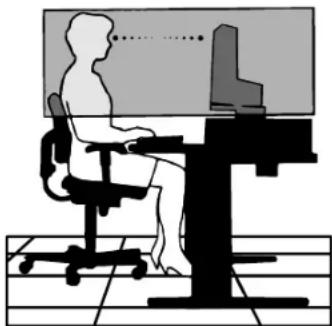
CORRECT PLACEMENT AND ADJUSTMENT OF THE MONITOR CAN REDUCE EYE, SHOULDER AND NECK FATIGUE. CHECK THE FOLLOWING WHEN YOU POSITION THE MONITOR:

- For optimum performance, allow 20 minutes for warm-up.
- Adjust the monitor height so that the top of the screen is at or slightly below eye level. Your eyes should look slightly downward when viewing the middle of the screen.
- Position your monitor no closer than 40 cm and no further away than 70 cm from your eyes. The optimal distance is 50 cm.
- Rest your eyes periodically by focusing on an object at least 20 feet away. Blink often.
- Position the monitor at a 90° angle to windows and other light sources to minimize glare and reflections. Adjust the monitor tilt so that ceiling lights do not reflect on your screen.
- If reflected light makes it hard for you to see your screen, use an anti-glare filter.
- Clean the LCD monitor surface with a lint-free, non-abrasive cloth. Avoid using any cleaning solution or glass cleaner!
- Adjust the monitor's brightness and contrast controls to enhance readability.
- Use a document holder placed close to the screen.
- Position whatever you are looking at most of the time (the screen or reference material) directly in front of you to minimize turning your head while you are typing.
- Avoid displaying fixed patterns on the monitor for long periods of time to avoid image persistence (after-image effects).
- Get regular eye checkups.
natural_image
Silhouette of a person sitting at a desk with a computer, no text or symbols visibleErgonomics
To realize the maximum ergonomics benefits, we recommend the following:
- Adjust the Brightness until the background raster disappears.
- Do not position the Contrast control to its maximum setting.
- Use the preset Size and Position controls with standard signals.
- Use the preset Colour Setting.
- Use non-interlaced signals with a vertical refresh rate between 60-75 Hz.
- Do not use primary colour blue on a dark background, as it is difficult to see and may produce eye fatigue to insufficient contrast.

VAROVÁNÍ

CHRAŃTE ZAŘÍZENÍ PŘED DEŠTĚM A VLHKEM. ZABRÁNÍTE TAK NEBEZPEČÍ POŽÁRU NEBO ÚRAZU ELEKTRICKÝM PROUDEM. POLARIZOVANOU ZÁSTRČKU JEDNOTKY NEPOUŽÍVEJTE VE SPOJENÍ SE ZÁSUVKOU PRODLUŽOVACÍ ŠNŮRY NEBO JINÝMI ZÁSUVKAMI, POKUD KOLÍKY NELZE ZCELA ZASUNOUT.
UVNITŘ ZAŘÍZENÍ SE NACHÁZÍ VYSOKONAPĚTOVÉ KOMPONENTY, PROTO SKŘÍŇ NEOTEVÍREJTE. SERVIS SVĚRTE KVALIFIKOVANÉ OSOBĚ.

UPOZORNĚNÍ

UPOZORNĚNÍ: PRO SNÍŽENÍ RIZIKA ÚRAZU ELEKTRICKÝM PROUDEM ZKONTROLUJTE, ZDA JE NAPÁJECÍ ŠNŮRA ODPOJENA ZE ZÁSUVKY. PRO ÚPLNÉ ODPOJENÍ ZDROJE NAPÁJENÍ OD JEDNOTKY ODPOJTE NAPÁJECÍ ŠNŮRU Z ELEKTRICKÉ ZÁSUVKY (NEOSTRAŇUJTE KRYT). UVNITŘ SE NENACHÁZEJÍ DÍLY, DO KTERÝCH UŽIVATEL MŮŽE ZASAHOVAT. SERVIS SVĚRTE KVALIFIKOVANÉ OSOBĚ.

Tokyo 108-0023, Japan

TÜV Rheinland Product Safety
ISO 13406-2

natural_image
Two computer units connected by cable, one with ports and arrows indicating data transfer (no visible text or symbols)natural_image
Front view of a computer tower with attached cable and ports (no visible text or labels)Obrázek A.2

natural_image
Two electronic devices connected by cables, one with ports and arrows indicating signal or data flow (no visible text or symbols)Obrázek RL.1
Otočení obrazovky
flowchart
graph TD
    A["Computer monitor with icon"] -->|Forward| B["Computer monitor with icon"]
    B -->|Reverse| A
    style A fill:#f9f,stroke:#333
    style B fill:#bbf,stroke:#333
Obrázek R.1
Česky-4
Sklon monitoru
natural_image
Illustration of hands interacting with a computer monitor displaying a brain icon, no text or symbols presentObrázek TS.1
Otáčení
natural_image
Illustration of two hands holding a tablet with a speech bubble icon, surrounded by curved arrows indicating rotation (no text or symbols)Obrázek TS.2

Obrázek S.2

Obrázek S.3
flowchart
graph LR
    A["Left Computer monitor"] --> B["Right computer monitor"]
    B --> C["Right computer monitor"]
natural_image
Silhouette of a person sitting at a desk with a computer, no text or symbols visibleErgonomika
natural_image
Coiled electrical outlet cable with two terminal plugs (no text or symbols visible)Netzkabel
natural_image
Illustration of a computer monitor with a separate Kabelabdeckung component (no text or symbols on the device itself)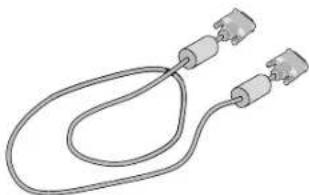
natural_image
Pure electrical circuit lines without any symbolsnatural_image
Two computer units connected by cable, one with ports and arrows indicating data transfer (no visible text or symbols)natural_image
Front view of a computer tower with ports and cables (no visible text or labels)Abbildung A.2
natural_image
Two electronic devices connected by cables, one with ports and connectors, the other with a display (no visible text or symbols)natural_image
Illustration of a computer monitor with ports and an attached cable (no text or symbols)Abbildung RL.1
Bildschirmdrehung
flowchart
graph LR
    A["Computer monitor with speech bubble"] -->|Forward| B["Computer monitor with speech bubble"]
    B -->|Reverse| A
natural_image
Illustration of hands interacting with a computer monitor displaying a brain icon, no text or symbols presentAbbildung TS.1
Drehen
natural_image
Illustration of two hands holding a tablet with a speech bubble icon, surrounded by curved arrows indicating rotation (no text or symbols)Abbildung TS.2
Abbildung S.2
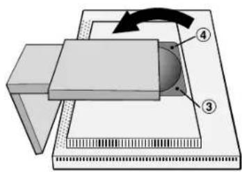
Abbildung S.3
natural_image
Silhouette of a person sitting at a desk with a computer, no text or symbols visibleErgonomie
natural_image
Two electronic devices connected by cable, one with ports and arrows indicating connection (no visible text or symbols)Σχήμα Α.1 Σχήμα Β.1
natural_image
Illustration of a computer tower with ports and cables (no text or symbols visible)Σχήμα Α.2
natural_image
Illustration of two connected devices with cables and ports, no visible text or symbolsnatural_image
Illustration of a computer monitor with ports and an external cable (no text or symbols)Σχήμα ΡΛ.1
natural_image
Illustration of hands holding a computer monitor with a curved interface, no text or symbols presentΣχήμα ΤΣ.1
Περιστροφή
natural_image
Illustration of two hands holding a tablet with a speech bubble, surrounded by curved arrows indicating rotation (no text or symbols)Σχήμα ΤΣ.2
Σχήμα Σ.2
Σχήμα Σ.3
natural_image
Silhouette of a person sitting at a desk with a computer, no text or symbols visibleΕργονομία
Directiva 89/336/CEE:
- EN 55022
- EN 61000-3-2
- EN 61000-3-3
- EN 55024
y lleva la marca

NEC-Mitsubishi Electric Visual
Systems Corporation
4-13-23, Shibaura,
Minato-Ku
natural_image
Two electronic devices with cables and ports, no visible text or symbolsFigura A.1 Figura B.1
natural_image
Front view of a computer tower with attached cable and ports (no visible text or symbols)Figura A.2

natural_image
Illustration of a computer setup with two connected devices, one front-mounted and one back-mounted, showing ports and cables (no text or symbols visible)Figura RL.1
flowchart
graph TD
    A["Computer monitor with icon"] -->|Forward| B["Computer monitor with icon"]
    B -->|Reverse| A
    style A fill:#f9f,stroke:#333
    style B fill:#bbf,stroke:#333
Figura R.1
Español-4
Inclinación
natural_image
Illustration of hands holding a computer monitor with a curved screen and directional arrows (no text or symbols)Figura TS.1
Giro
natural_image
Illustration of a person holding a tablet with a speech bubble, surrounded by curved arrows indicating rotation (no text or symbols)Figura TS.2
Figura S.2

Figura S.3
natural_image
Silhouette of a person sitting at a desk with a computer, no text or symbols presentErgonomía
Systems Corporation 4-13-23, Shibaura,
Minato-Ku Tokyo 108-0023, Japon

natural_image
Two electronic devices with connected cables, one showing ports and arrows, the other displaying a screen (no visible text or symbols)Figure A.1 Figure B.1

natural_image
Front view of a computer tower with attached cable and ports (no visible text or symbols)Figure A.2

natural_image
Illustration of a computer setup with two connected devices, one front-mounted and one back-mounted, showing ports and cables (no text or symbols visible)Figure RL.1
Rotation de l'écran
natural_image
Illustration of hands holding a computer monitor with a curved screen, no text or symbols presentFigure TS.1
Pivotement
natural_image
Illustration of a person holding a tablet with a speech bubble, surrounded by curved arrows indicating rotation (no text or symbols)Figure TS.2
Figure S.2

Figure S.3
natural_image
Silhouette of a person sitting at a desk with a computer, no text or symbols presentErgonomie
natural_image
Two electronic devices with cables and ports, no visible text or symbolsFigura A.1 Figura B.1

natural_image
Front view of a computer tower with attached cable and ports (no visible text or labels)Figura A.2
natural_image
Illustration of two connected devices with cables and connectors, no visible text or symbolsnatural_image
Illustration of a computer monitor with ports and an external cable (no text or symbols)Figura RL.1
flowchart
graph TD
    A["Computer monitor with abstract internal shape"] -->|Forward| B["Computer monitor with abstract internal shape"]
    B -->|Reverse| A
    style A fill:#f9f,stroke:#333
    style B fill:#bbf,stroke:#333
Figura R.1
Italiano-4
Inclinazione
natural_image
Illustration of hands holding a computer monitor with a curved screen and directional arrows (no text or symbols)Figura TS.1
Rotazione
natural_image
Illustration of a person holding a tablet with a speech bubble, surrounded by curved arrows indicating rotation (no text or symbols)Figura TS.2
Figura S.2

Figura S.3
natural_image
Silhouette of a person sitting at a desk with a computer, no text or symbols visibleMultiSync LCD1980SX (L192G3) in
overeenstemming is met
Tokyo 108-0023, Japan

natural_image
Two electronic devices with attached cables, one connected via cable to the other (no visible text or symbols)natural_image
Front view of a computer tower with attached cable and ports (no visible text or labels)Illustratie A.2

natural_image
Illustration of a computer setup with two connected devices, one front-mounted and one back-mounted, showing ports and cables (no text or symbols visible)natural_image
Illustration of a computer monitor with ports and cable, no text or symbols presentIllustratie RL.1
Scherm roteren
flowchart
graph TD
    A["Computer monitor with abstract shape"] --> B["Computer monitor with abstract shape"]
    B --> C["Device with hand icon"]
    style A fill:#f9f,stroke:#333
    style B fill:#bbf,stroke:#333
    style C fill:#dfd,stroke:#333
natural_image
Illustration of hands interacting with a computer monitor displaying a brain icon, no text or symbols presentIllustratie TS.1
natural_image
Illustration of a person holding a tablet with a speech bubble, surrounded by curved arrows indicating rotation (no text or symbols)Illustratie TS.2
Illustratie S.2

Illustratie S.3
natural_image
Silhouette of a person sitting at a desk with a computer, no text or symbols visiblenatural_image
Two computer units connected by cable, one with ports and arrows indicating data transfer (no visible text or symbols)natural_image
Front view of a computer tower with attached cable and ports (no visible text or symbols)Rysunek A.2
natural_image
Illustration of a computer tower connected to a server unit via cables (no text or symbols visible)Rysunek RL.1
Obroty ekranu
natural_image
Illustration of hands holding a computer monitor with a curved screen and directional arrows (no text or symbols)Rysunek TS.1

natural_image
Illustration of a person holding a tablet with a speech bubble, surrounded by curved arrows indicating rotation (no text or symbols)Rysunek TS.2
Rysunek S.2
Rysunek S.3
DOWN/UP (POZYCJA PIONOWA)
natural_image
Silhouette of a person sitting at a desk with a computer, no text or symbols presentErgonomia
natural_image
Two horizontal grayscale color swatches with a central crosshair and alignment lines (no text or symbols)
natural_image
Two isolated geometric symbols: a crosshair and a square with a dot, on a plain background (no text or labels)Polski-12

ПРЕДУПРЕЖДЕНИЕ

natural_image
Two electronic devices with cables and ports, no visible text or symbolsnatural_image
Front view of a computer tower with attached cable and ports (no visible text or labels)Рисунок А.2
natural_image
Illustration of a computer setup with two connected devices, one front-mounted and one back-mounted, showing ports and cables (no text or symbols visible)Рисунок RL.1
Поворот экрана
natural_image
Illustration of hands interacting with a computer monitor displaying a brain icon (no text or symbols)Рисунок TS.1
Поворот
natural_image
Illustration of hands holding a computer monitor with a speech bubble icon, surrounded by curved arrows indicating rotation (no text or symbols)Рисунок TS.2
Рисунок S.2

Рисунок S.3
Внимание.
ПРИМЕЧАНИЕ. OSM must be closed in order to change signal input.
Меню
natural_image
Silhouette of a person sitting at a desk with a computer, no text or symbols presentЭргономика
natural_image
Two electronic devices with cables and ports, no visible text or symbolsŞekil A.1 Şekil B.1

natural_image
Front view of a computer tower with attached cable and ports (no visible text or labels)Şekil A.2

natural_image
Illustration of two connected devices with cables and connectors, no visible text or symbolsŞekil RL.1
Ekranın Dönmesi
Şekil R.1
Türkçe-4
Eğim
natural_image
Illustration of hands holding a computer monitor with a curved screen and directional arrows (no text or symbols)Şekil TS.1
Açıklık
natural_image
Illustration of a person holding a tablet with a speech bubble, surrounded by curved arrows indicating rotation (no text or symbols)Şekil TS.2
Şekil S.2

Şekil S.3
natural_image
Silhouette of a person sitting at a desk with a computer, no text or symbols present


- Canadian Department of Communications Compliance Statement
- FCC Information
- Declaration of Conformity
- TCO'99 (Black model)
- Why do we have environmentally labelled computers?
- What does labelling involve?
- Environmental Requirements
- Flame retardants
- Lead\*\*
- Cadmium\*\*
- Mercury\*\*
- CFCs (freons)
- TCO'03 (White model)
- TcODevelopment
- Congratulations!
- Ergonomics
- Energy
- Emissions
- Ecology
- Manufacturer's Recycling and Energy Information
- Index
- CAUTION
- Caution:
- Declaration
- Declaration of the Manufacturer
- Contents
- Quick Start
- Raise and Lower Monitor Screen
- Screen Rotation
- Tilt
- Swivel
- Remove Monitor Stand for Mounting
- English-5
- Controls
- OSM (On-Screen Manager) control buttons on the front of the monitor function as follows:
- Menu
- Brightness/Contrast Controls
- BRIGHTNESS
- CONTRAST
- AUTO AUTO CONTRAST (Analog input only)
- AUTO BRT AUTO BRIGHTNESS
- AUTO Auto Adjust (Analog input only)
- Image Controls
- LEFT / RIGHT
- DOWN / UP
- SIZE (OSD ROTATION: Landscape) or V. SIZE (OSD ROTATION: Portrait) (Analog input only)
- ↔|| FINE (Analog input only)
- RGB Color Control Systems
- Tools 1
- English-7
- Tools 2
- Information
- OSM Warning
- Recommended use
- Safety Precautions and Maintenance
- CORRECT PLACEMENT AND ADJUSTMENT OF THE MONITOR CAN REDUCE EYE, SHOULDER AND NECK FATIGUE. CHECK THE FOLLOWING WHEN YOU POSITION THE MONITOR:
- VAROVÁNÍ
- UPOZORNĚNÍ
- Otočení obrazovky
- Sklon monitoru
- Otáčení
- Ergonomika
- Bildschirmdrehung
- Drehen
- Ergonomie
- Περιστροφή
- Εργονομία
- Inclinación
- Giro
- Ergonomía
- Rotation de l'écran
- Pivotement
- Inclinazione
- Rotazione
- Scherm roteren
- Obroty ekranu
- DOWN/UP (POZYCJA PIONOWA)
- Ergonomia
- ПРЕДУПРЕЖДЕНИЕ
- Поворот экрана
- Поворот
- Эргономика
- Ekranın Dönmesi
- Eğim
- Açıklık
Brand : NEC
Model : MultiSync LCD1980SX
Category : Monitor