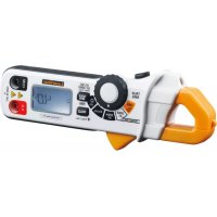
MultiClampMeter Pro - Measuring equipment Laserliner - Free user manual and instructions
Find the device manual for free MultiClampMeter Pro Laserliner in PDF.


| Product type | Digital multimeter clamp |
| Brand | Laserliner |
| Model | MultiClampMeter Pro |
| AC current measurement | 200 A (True RMS), accuracy ±2.5% + 8 digits, 50/60 Hz |
| DC current measurement | 200 A, accuracy ±2.0% + 5 digits |
| AC voltage measurement | 600 V (True RMS), accuracy ±1.5% + 8 digits, 50/400 Hz |
| DC voltage measurement | 600 V, accuracy ±1.0% + 2 digits |
| Resistance measurement | 999.9 Ω, accuracy ±1.5% + 8 digits |
| Continuity test | Threshold <30 Ω, test current <0.5 mA, audible signal |
| Clamp opening | 17 mm max |
| Overvoltage category | CAT III - 600 V |
| Power supply | 2 AAA alkaline 1.5 V batteries |
| Dimensions (L x W x H) | 164 x 65 x 32 mm |
| Weight | 175 g |
| Display | LCD screen with backlight, digital display and bargraph |
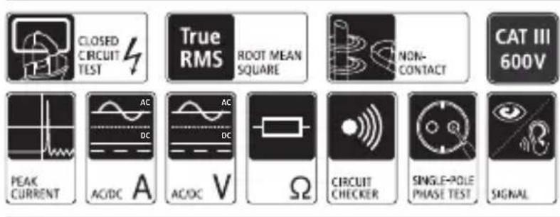
| Special functions | PEAK hold, MAX/MIN, Hold, DCA Zero, Non-contact voltage detection (100-600 V AC), Flashlight, Auto power off (10 min) |
| Operating temperature | -10°C to 50°C |
| Storage temperature | -30°C to 60°C |
| Maximum relative humidity | 90% (0-30°C), 75% (30-40°C), 45% (40-50°C), non-condensing |
| Maximum operating altitude | 3000 m |
| Safety and EMC standards | EN 61010-1, EN 61010-2-031, EN 61326 |
| Recommended calibration | Once a year |
Frequently Asked Questions - MultiClampMeter Pro Laserliner
User questions about MultiClampMeter Pro Laserliner
0 question about this device. Answer the ones you know or ask your own.
Ask a new question about this device
Download the instructions for your Measuring equipment in PDF format for free! Find your manual MultiClampMeter Pro - Laserliner and take your electronic device back in hand. On this page are published all the documents necessary for the use of your device. MultiClampMeter Pro by Laserliner.
USER MANUAL MultiClampMeter Pro Laserliner

!
line
| t | u | | --- | ----- | | 1 | +0.5 | | 2 | -0.5 | | 3 | 0 |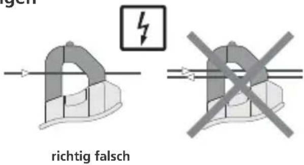

Read the operating instructions and the enclosed brochure „Guarantee and additional notices“ completely. Follow the instructions they contain. Safely keep these documents for future reference.
Function/Application
Current and voltage multimeter for taking measurements in the range of overvoltage category CAT III up to max. 600V. The meter can be used to measure DC and AC voltages and direct and alternating currents, resistance and for continuity tests within the specified ranges. Furthermore, the device features a PEAK function, a MAX/MIN display, a hold function and a True RMS measurement (Root-Mean-Square) function. The device is also equipped with a torch and an illuminated display.
Safety instructions
- The device must only be used in accordance with its intended purpose and within the scope of the specifications.
- Before taking any measurements, make sure that both the area to be tested (e.g. a line), the test device and the accessories used (e.g. connection cable) are in proper working order. Test the device by connecting it to known voltage sources (e.g. a 230 V socket in the case of AC testing or a car battery in the case of DC testing). Stop using the device if one or a number of its functions fails.
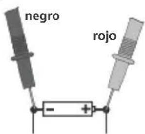
- If you are working with voltages higher than 25 V AC/60 V DC, exercise extreme caution. Touching the electrical conductors at such voltages poses a risk of life-threatening electric shocks.
- Make sure that you always select the correct connections, the correct rotary switch position and the correct range for the measurement to be taken.
- Before measuring or checking the resistance, continuity, diodes or capacitance, disconnect the power supply to the electric circuit. Check that all high-voltage capacitors are discharged.
- Only the original measuring leads may be used. Their voltage, category and ampere rated powers must match those of the measuring device.
- If you have to take hold of the measuring spikes, do so by the grip sections only. Do not touch the measuring contacts whilst the measurement is being taken.
-
Do not use the device in environments in which there are con-ductive particles or where the occurrence of moisture (in the form of condensation, for example) can create transient conductivity.
-
If the device comes into contact with moisture or other conductive residue, work must not be carried out under voltage. At and above voltages of 25 V AC/60 V DC, the presence of moisture creates the risk of life-threatening electric shocks. Clean and dry the device before use. When using the device outdoors, make sure that the weather conditions are appropriate and/or that suitable protection measures are taken.
- If you are taking measurements in the hazardous vicinity of electrical installations, do not work alone and seek guidance from an electrically skilled person before starting work.
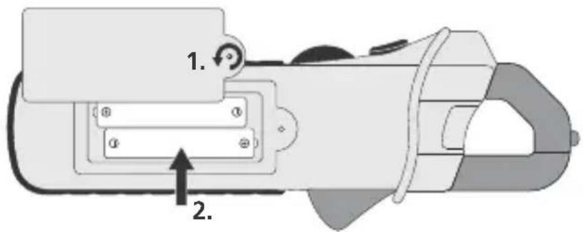
- Isolate the device from all current sources before opening the battery compartment cover.
- If possible, do not work alone.
Symbols
Hazardous electrical voltage warning: Unprotected live components inside the device housing may pose a risk of electric shock.

Danger area warning

Protection class II: The test device has reinforced or double insulation.
CAT III
Overvoltage category III: Equipment in fi xed installations and for applications where specific requirements with regard to the reliability and availability of equipment have to be met, e.g. circuit-breakers in fi xed installations and devices used in industrial applications which are permanently connected to the fi xed installation.

1 Sensor (non-contact voltage detector)
2 Current clamp
3 Flashlight
4 Flashlight ON/OFF
5 Rotary switch to change measuring functions
6 „PEAK“, „MAX/MIN“, „DCA Zero“, „AC/DC“ toggle switch
7 LC display
8 COM input socket
9 AC warning
10 Clamp opening button
11 Hold function / backlighting ON/OFF
12 V Ω input socket
13 Test prods Measuring
14 Contacts
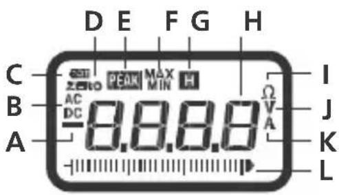
A Negative measured value
B Direct (DC) or alternating (AC) variables
C Low battery charge
D ADC zero position
E PEAK function
F MAX/MIN display
G Hold function
H Measured value display
I Ω measurement module
J V measurement module
K A measurement module
L Measurement scale
Display:
O.L.: Open line/overfl ow: measuring circuit not closed or measuring range exceeded
AUTO OFF function
In order to preserve the batteries, the device switches off automatically if left idle for 10 minutes. A signal sounds in advance.
1 Insertion of batteries
2 AC current measurements
1.2.
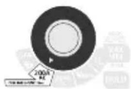
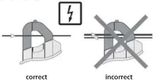
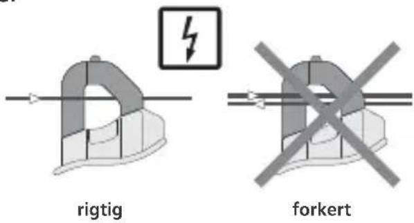
- Turn the rotary switch to position „200A AC“.
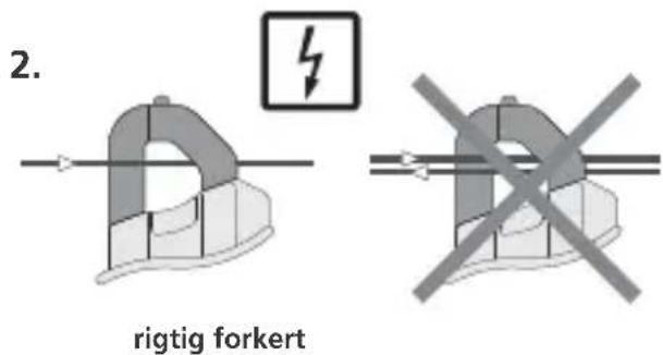
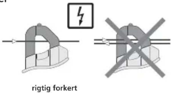
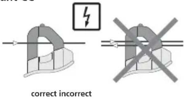
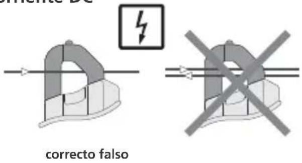
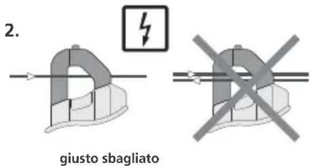
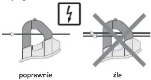
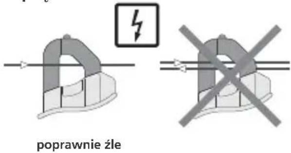
- Place the current clamp around a line.
- The measured value is shown on the LC display.
3 PEAK hold function
1.
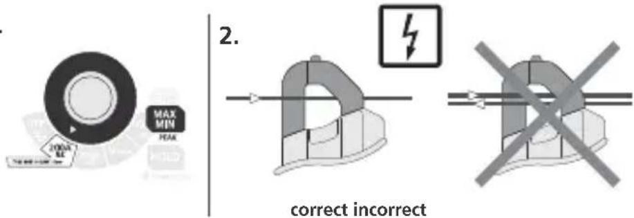
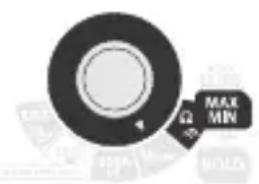
- Turn the rotary switch to position „200A AC“ and press the „MAX/MIN“ button, to activate the PEAK function.
- Place the current clamp around a line.
- Switch on the consumer unit you want to measure. The signifi cant maximum value (10 \~ 282.8 A) is displayed. The measuring device can detect fast current peaks (<10 milliseconds).
©
- The measured value is shown on the LC display. By pressing the „MAX/MIN“ button, the minimum and maximum values are measured and displayed.

When measuring voltage, the resistance measurement and continuity test functions must not be activated.
7 DCA Zero
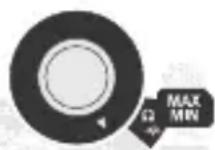
When measuring DC voltages, reset the value by pressing the „MAX/MIN“ button and holding it down for 2 seconds to calibrate the electronic measuring equipment. By pressing the „MAX/MIN“ button repeatedly, the minimum and maximum values are measured displayed.
Resistance measurement

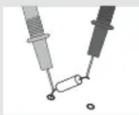
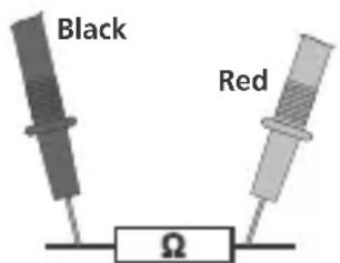
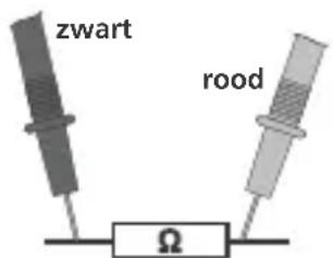
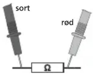
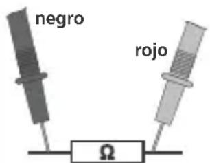
Resistances can only be measured correctly in isolation; therefore, the components might need to be disconnected from the remainder of the circuit.
natural_image
Pure electrical circuit lines without any symbols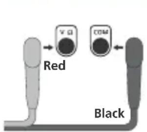
2.3.1.
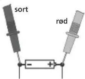
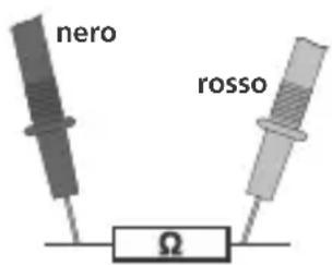
- Connect the red test prod to the V Ω input socket (12) and the black test prod to the COM input socket (8).
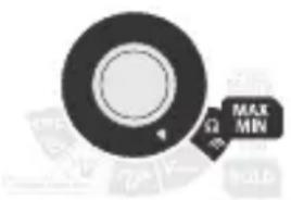
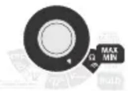
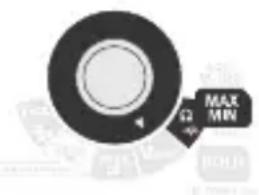
- Turn the rotary switch to position „Ω“.
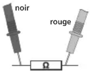
- Connect the measuring contacts to the object to be tested.
- The measured value is shown on the LC display. If the measured value is < 30 , a signal sounds.

When measuring resistance, to avoid the risk of the results of a measurement being distorted, there must be no traces of dirt, oil, solder spray or other contamination on the test prods.

When measuring resistance, the components must be zero-potential.
9 MAX/MIN function
Press the „MAX/MIN“ button to deactivate the function. The measured „MAX“ value is shown on the display and is automatically updated, when a new maximum value is detected.
Press the button again to display the „MIN“ value. This value is updated, when a new „MIN“ value is detected.
Press the „MAX/MIN“ button again, to display the current value. The „MAX“ and „MIN“ values are still being updated.
Press the button and hold it down for 2 seconds to exit this mode.
10 Continuity test
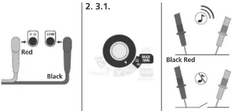
-
Connect the red test prod to the V Ω input socket (12) and the black test prod to the COM input socket (8).
-
Turn the rotary switch to position „·””.
-
Connect the measuring contacts to the object to be tested. If the test has been positive, an acoustic signal sounds. (< 30 Ω)

For continuity tests, the components must be zero-potential.
Hold function
To briefly hold the current measured value, press the „HOLD" button. In order to take measurements, this function must be deactivated by pressing the button again.
12 Voltage detection, non-contact (AC warning)
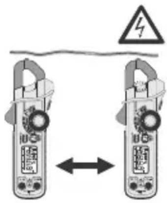
The non-contact voltage detector integrated in the meter is able to detect AC voltages from 100 V to 600 V. Switch the device on and run the voltage sensor along the object to be tested (5 - 10 mm). The display (9) lights up if AC voltage is detected.
!
Non-contact voltage detection is no substitute for conventional voltage testing. As the device detects an electrical fi eld, it will react even to static charge.
Voltage detection, single-pole phase test
Remove the black test prod from the device. Turn the rotary switch to position „V AC/DC“ and connect the red test prod to the phase or neutral conductor. The red display (9) only lights up if the phase conductor is live. When the single-pole phase test is carried out on the outer conductor, the indicator function may be adversely affected under certain conditions (e.g. when insulating personnel protective equipment is used or at insulated locations).
!
The single-pole phase test is not suitable for checking for zero voltage. To do this, you need to carry out a two-pole phase test.
13 Flashlight function
To switch on the fl ashlight, press and hold down the corresponding button. The light switches itself off automatically as soon as the button is released.
14 Backlight
To switch the backlighting on, press the „Hold“ button (11) and hold it down for 2 seconds. Press the „Hold“ button twice, to switch the backlighting off.
15 Calibration
The meter needs to be calibrated and tested on a regular basis to ensure it produces accurate measurement results. We recommend carrying out calibration once a year.
Technical data
| Function | Range | |
| AC current (50/60 Hz) True RMS 200.0 AAC ± (2.5% ± 8 digits) | ||
| DC current 200.0 ADC ± (2.0% ± 5 digits) | ||
| DC voltage 600.0 VDC ± (1.0% ± 2 digits) | ||
| AC voltage (50/60 Hz) True RMS 600.0 VAC ± (1.5% ± 8 digits) | ||
| Resistance 999.9 Ω ± (1.5% ± 8 digits) | ||
| Function | Max. in | |
| A AC / VDC 200A (PEAK 282, 8A) | ||
| V DC, V AC 600V DC/AC | ||
| Resistance, continuity test | 600V DC/AC | |
| Clamp opening | approx. 17 mm | |
| Capacitance measurement | Response threshold <30 Ω, Test current <0.5 mA | |
| Measurement range | 10 measurements/sec. for numme-ric display & 40 measurements/sec. for bar graph display (DCA, DCV, resistance measuring) | |
| Input resistance | 1.0 MΩ (VDC, VAC) | |
| Frequency range AC current/voltage | 50/400 Hz (True RMS) | |
| PEAK hold | measures peak current <10 ms | |
| MAX/MIN hold | Measurement range <500 ms | |
| Operating temperature | -10°C ... 50°C | |
| Storage temperature | -30°C ... 60°C | |
| Humidity | non-condensing 90% (0°C ... 30°C); 75% (30°C ... 40°C); 45% (40°C ... 50°C) relative humidity | |
| Height above mean sea level | Operation: 3,000 m; Storage: 10,000 m | |
| Overvoltage category | CAT III - 600V | |
| Power supply | 2x 1.5 Type AAA, LR03, alkaline | |
| Dimensions | 164 x 65 x 32 mm | |
| Weight | 175 g | |
| Test standards | EN 61326; EN 61010-1; EN 61010-2-031 | |
Subject to technical alterations. 07.2010.
EU directives and disposal
This device complies with all necessary standards for the free movement of goods within the EU.
This product is an electric device and must be collected separately for disposal according to the European Directive on waste electrical and electronic equipment.
Further safety and supplementary notices at:
www.laserliner.com/info
!
line
| t | u | | --- | ----- | | 1 | +0.5 | | 2 | -0.5 | | 3 | 0 |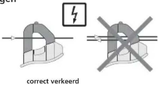
natural_image
Pure electrical circuit lines without any symbols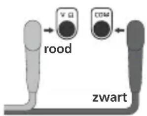
2.3.1.

natural_image
Simple line drawing of two mechanical components with a cylindrical shaft and base, no text or symbols present.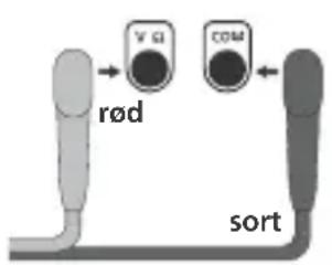
flowchart
graph TD
    A["rød"] --> B["V Q"]
    B --> C["COM"]
    C --> D["sort"]
2.3.1.

natural_image
Pure electrical circuit lines without any symbols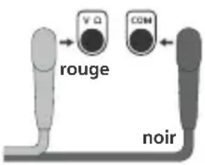
2.3.1.
!
natural_image
Pure electrical circuit lines without any symbols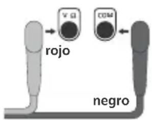
!
line
| t | u | | --- | ----- | | 1 | +0.5 | | 2 | -0.5 | | 3 | 0 |
natural_image
Pure mechanical assembly diagram without any text, numbers, or symbols
2.3.1.
!
natural_image
Two-panel illustration showing a power supply device and its electrical circuit board, both with warning symbols (no readable text or labels)SERVICE

Umarex GmbH & Co KG
- Laserliner -
083.040A / Rev. 0710
Umarex GmbH & Co KG
Donnerfeld 2
59757 Arnsberg, Germany
- !
- Function/Application
- Safety instructions
- Symbols
- CAT III
- AUTO OFF function
- Insertion of batteries
- AC current measurements
- PEAK hold function
- DCA Zero
- Resistance measurement
- MAX/MIN function
- Continuity test
- Hold function
- Voltage detection, non-contact (AC warning)
- Voltage detection, single-pole phase test
- Flashlight function
- Backlight
- Calibration
- EU directives and disposal
- Umarex GmbH & Co KG
Brand : Laserliner
Model : MultiClampMeter Pro
Category : Measuring equipment