VT 1 - Measuring equipment BENNING - Free user manual and instructions
Find the device manual for free VT 1 BENNING in PDF.

| Brand | BENNING |
| Model | VT 1 |
| Product type | Non-contact phase and cable break detector |
| Nominal voltage range | 200 V to 1,000 V AC |
| Frequency range | 45 Hz to 65 Hz |
| Overvoltage category | CAT III 1,000 V / CAT IV 600 V |
| Pollution degree | 2 |
| Protection type | IP 40 |
| Operating temperature | -0 °C to +40 °C, humidity ≤ 80% |
| Storage temperature | -20 °C to +60 °C, humidity ≤ 80% (without batteries) |
| Dimensions (L x W x H) | 152 x 22 x 18 mm approx. |
| Weight | 40 g approx. (without batteries) |
| Power supply | 2 micro LR03/AAA batteries (1.5 V) |
| Display | Red LED (test tip) and acoustic signal |
| Main functions | Phase detection, cable break detection |
| Safety | Double insulation (class II), compliance with DIN EN 61010-1, DIN EN 61326 |
| Maintenance and cleaning | External cleaning with dry cloth; remove batteries for prolonged storage |
| Spare parts and repairability | Batteries (2x LR03/AAA); support via hotline and manufacturer |
Frequently Asked Questions - VT 1 BENNING
User questions about VT 1 BENNING
0 question about this device. Answer the ones you know or ask your own.
Ask a new question about this device
Download the instructions for your Measuring equipment in PDF format for free! Find your manual VT 1 - BENNING and take your electronic device back in hand. On this page are published all the documents necessary for the use of your device. VT 1 by BENNING.
USER MANUAL VT 1 BENNING
text_image
BUNNING VT-1BENNING
text_image
BUNNING VT 1A
text_image
BENNING VT 1 1 2 3 4B
230 VAC
text_image
PE N L BENNING VT 1 BENNING VT 1C

text_image
BENNING 11 BEN ?Operating Manual Non-Contact Phase Indicator and Cable Break Detector BENNING VT 1
Before using the BENNING VT 1 phase indicator and cable break detector: Please read the operating manual and absolutely observe the safety instructions!
1. Safety instructions
- Check the phase indicator and cable break detector for correct functioning immediately before and after using it (see chapter 3)! Do not use the indicator, if one or more indications are not working or if it does not seem to be ready for operation!
- During the tests, touch the indicator at the red handle behind the grip limit ② only and do not touch the white probe tip ①!
- The indicator must be used only within the stated nominal voltage range from 200 V to 1,000 V AC and in earthed mains supply circuits of overvoltage cat egory CAT III 1,000 V or CAT IV 600 V for phase-to-earth measurements.
- The BENNING VT 1 phase indicator and cable break detector detects fields of phase/external conductor voltages from approx. 200 V alternating voltage (AC) on. Direct voltage (DC) fields will not be detected!
- Please observe that work on live parts and electrical components of all kinds is dangerous! Even low voltages of 30 V AC and 60 V DC may be dangerous to human life!
- The BENNING VT 1 phase indicator and cable break detector is not a substitute for a two-pole voltage tester such as e.g. the DUSPOL® to determine the ab sence of voltage.
-
The following factors might affect the correct functioning of the phase test and cable break detect:
-
excessive distance to the phase (external conductor) to be tested
- excessive insulation and shielding of the phase (external conductor)
- protective clothing and insulating conditions on site
- constructional differences of sockets / CEE couplings with recessed contacts, e.g. 63 A CEE coupling
- mains failures or lacking mains quality
-
battery condition
-
Do not operate the device with the battery compartment being open.
- The indicator is designed for being used by qualified electricians and under safe working conditions.
- The indicator must be protected against contamination and damaging of the housing surface.
Electrical symbols on the device:
| Symbol Meaning | |
 | Attention! Please observe documentation!This symbol indicates that the information provided in the operating manual must be complied with in order to avoid risks. |
 | This symbol on the BENNING VT 1 indicates that the indicator is equipped with protective insulation (protection class II). |
 | Alternating voltage |
 | Earth (voltage to earth) |
 | This symbol shows the orientation of the batteries for inserting them with correct polarity. |
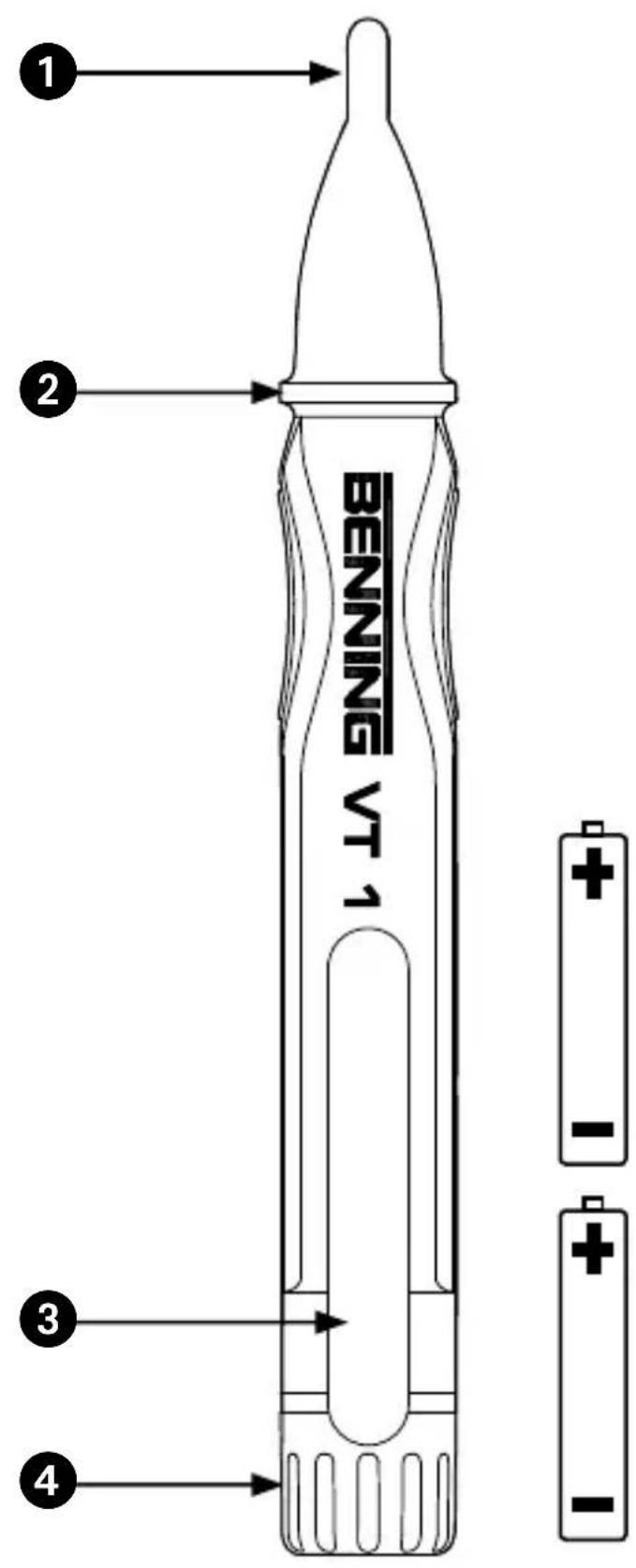
2. Device description (figure A)
① Probe tip with LED indication (red)
② Grip limit
3 Clip
4 Battery compartment cover
3. Functional test
- Check the phase indicator and cable break detector for correct functioning immediately before and after using it!
- Test the phase test for correct functioning with a familiar voltage source, e.g. a 230 V socket/5-pin CEE socket.
- Please replace the batteries as soon as the red LED indication ① or the acoustic signal are getting weaker.
- Do not use the BENNING VT 1, if not all functions are working properly!
- The BENNING VT 1 has no circuit breaker and is always enabled. A special circuit with low current consumption extends the battery lifetime and thus ensures that the device is ready for use.
4. How the indicator works
- The BENNING VT 1 phase indicator and cable break detector detects electric fields generated by phase/external conductor voltages from 200 V to 1,000 V AC (45 Hz to 65 Hz) on.
- If an electric field is detected, the probe tip ① lights up in red color and an acoustic signal is emitted. The flashing frequency of the red probe tip ① as well as the frequency of the acoustic signal increase with the electric field or the voltage applied increasing as well.
- The BENNING VT 1 phase indicator and cable break detector can be used to determine the phase (external conductor) of an AC voltage.
- The test does not require any current flow and no electrically conductive contact with the system part, socket or insulated line.
- Please observe that the BENNING VT 1 only responds to sufficiently strong fields with a phase/external conductor voltage from 200 V AC on.
If the BENNING VT 1 phase indicator and cable break detector does not react, the distance to the live system part might be too large, the system part might be shielded or the insulation might be too thick.
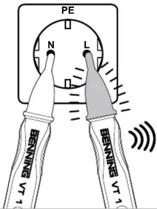
5. Phase/external conductor test of an AC voltage (figure B)
- Place the probe tip ① onto the assumed phase (external conductor) of the system part.
- If the phase (external conductor) has been detected, this is confirmed by an acoustic signal and by the probe tip ① lighting up in red color.
Attention!
Please observe that even if the BENNING VT 1 does not indicate a phase (external conductor), a dangerous voltage may be applied to the test object nevertheless. For determining the absence of voltage, only use a two-pole voltage tester complying with the DIN EN 61243-3 (VDE 0682-401) standard, e.g. a DUSPOL® voltage tester.
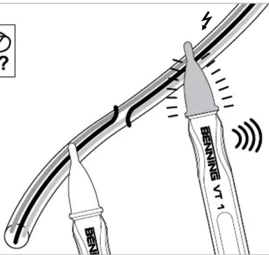
6. Testing of interruptions of live lines (figure C)
To localize interruptions of live lines (e.g. a cable break in a cable reel or defective lamps in a chain of lights), pass the probe tip ① along the insulated line from the feeding point (phase) in direction of the other end of the line. The point of interruption is located as soon as the phase (external conductor) is no longer indicated by the acoustic signal and the test probe lighting up.
For testing a cable reel, make sure to turn the shock-proof plug by 180^ in order to connect both lines to the phase (external conductor) of a shock-proof socket.
7. Battery replacement (figure A)
- Do not apply voltage to the device when the battery compartment is open!
- Remove the battery compartment cover ④ from the indicator and remove the used batteries.
- Insert new micro batteries (LR03/AAA) into the indicator observing correct polarity (positive pole first).
- Screw the battery compartment cover ④ back onto the indicator.
8. Technical data
- regulation: DIN EN 61010-1, DIN EN 61326
- nominal voltage/frequency range: 200 V to 1,000 V AC/45 Hz to 65 Hz
- overvoltage category: CAT III 1,000 V/CAT IV 600 V
- contamination level: 2
- protection category: IP 40 (DIN EN 60529) means:
Protection against access to dangerous parts and protection against solid impurities of a diameter > 1.0 mm, (4 - first index).
No protection against water, (0 - second index).
- operating temperature range: - 0 °C to + 40 °C, air humidity ≤ 80 %
- storage temperature range: - 20 °C to + 60 °C, air humidity ≤ 80% (without batteries)
- dimensions of the indicator (L x W x H): approx. 152 x 22 x 18 mm
- weight: approx. 40 g (incl. batteries)
- battery type: 2 x micro, LR03/AAA (1.5 V)
The BENNING VT 1 phase indicator and cable break detector does not work with the battery being exhausted!
9. General maintenance
Clean the exterior of the device with a clean dry cloth.
If there is contamination or deposits in the area of the battery or the battery housing, clean these areas as well by means of a dry cloth. If the device is stored for a longer period of time, remove the batteries from the device!
10. Environmental protection
At the end of product life, dispose of the unserviceable device as well as used batteries via appropriate collecting facilities provided in your community.
11. Product support
Please contact the expert personnel of the supplier or manufacturer for further information.