85 SE - Coffee machine La San Marco - Free user manual and instructions
Find the device manual for free 85 SE La San Marco in PDF.

User questions about 85 SE La San Marco
0 question about this device. Answer the ones you know or ask your own.
Ask a new question about this device
Download the instructions for your Coffee machine in PDF format for free! Find your manual 85 SE - La San Marco and take your electronic device back in hand. On this page are published all the documents necessary for the use of your device. 85 SE by La San Marco.
USER MANUAL 85 SE La San Marco
MACHES A CAFÉ EXPRESS
Translation of the original instructions
Index
- Introduction 23
1.1 Using the manual . . . . . . . . . . . . . . . . . . . . . . . . . . . . . . . . . . . . . . .
1.2Warnings 23
1.3 Starting the coffee machine.. .24
-
Exploded diagrams . 25
-
Diagram of water feed system . 26
-
Technical specifications . 27
-
Installation.. .27
5.1 Equipment in machine kit. . 28
5.2 Prearrangement of water supply . . . . . . . . . . . . . . . . . . . . . . . . . . . . . . . . . . . . . . . . . . . . . . . . .
5.3 Water softener (optional) . 28
5.4 Installation of the water system.. 28
5.5 Drainage.. 29
5.6 Electrical connections . 29
5.7 Connection to the equipotential clamp . . . . . . . . . . . . . . . . . . . . . . . . . . . . . . . . . . . . . . . . . . . . . .
- Operating instructions.. 31
6.1 Filling the boiler . 31
6.2 Calibration of pump pressure.. . 31
6.3 Calibration of water pressure in the boiler.. 31
6.4 Heating the water in the boiler.. 31
6.5 Electric cup warmer (Optional). 32
6.6 Steam delivery . 32
6.7 Hot water delivery . 32
6.8 Preparation of ground coffee.. 32
6.9 Brewing coffee . 32
6.10 Draining the boiler . 32
6.11 Automatic operation - programming the coffee brewing cycles . 32
6.12 Alarms . 33
- Instructions for Authorized Installer
Gas fired Boiler (Optional) . 33
7.1 Connection to gas supply . 33
7.2 Venting the combustion fumes . 33
7.3 Ignition . 34
7.4 Changing the calibration . 34
- Routine maintenance
8.1 Cleaning the serving units and the filter holder . 35
8.2 Cleaning the tray and the cup support grill . 36
8.3 Cleaning the steam spout . 36
8.4 Substitution of boiler water . 36
-
Idle periods.
-
Information for users in the European community.. .pag. 36
- Guarantee
- Declaration of conformity C E
- Problem solving . 38
1. Introduction

IMPORTANT
Before using the machine, carefully read all of the instructions contained in this machine.
1.1 Using the manual

This manual contains all information required for the installation, use and maintenance of the coffee machine.
This manual is an integral part of the machine; always keep it intact together with the appliance.
1.2Warnings

-
Do not operate the machine or carry out routine maintenance before reading this manual.
-
This machine is designed and built for serving espresso coffee, hot water (for the preparation of beverages and infusions) and steam (used to heat liquids). The use of the machine for any other than its intended purposes is considered to be improper and unauthorized. The manufacturer declines any liability for damage resulting from the improper use of the machine.
- This machine must be installed only in places where its use and its maintenance are made by trained personnel.
- The device must be connected to the local water mains using a flexible pipe fitting in compliance with national standards, if these are applicable. Furthermore, the equipment must be installed with suitable "reflux protection" in order to comply with the applicable national and local regulations.
Install the machine on a plane at a height of not less than 800mm above the floor.
The scheduled maintenance and repair should only be performed by authorized and qualified personnel. - Do not install the espresso coffee machine in places where cleaning is likely to be carried out with jets of water. Do not immerge the unit in water to clean it.
If the power cord is damaged its replacement should be performed only by authorized and qualit personnel. - The user must be a responsible adult, who is expected to comply with local safety rules and accepted common sense procedures. For a proper and safe use of the machine, the operator must always comply with applicable accident prevention and other work safety and health regulations.
- This appliance is not designed for use by persons (including children) with limited physical, sensory or mental abilities, or lacking in experience and knowledge, unless they are controlled and taught to use the appliance by a person responsible for their safety. Children must be supervised to make sure they do not play with the appliance.
- The use of the appliance and the routine maintenance and cleaning operations may only be carried out by authorized personnel, under the responsibility of the client.
- The machine must never be switched on before connecting it to the water supply. The user must make sure that the water supply valve remains open when the machine is switched on. Place only empty cups in the cup holding shelf.
The machine in operation must never be covered, as there must be a proper air circulation around it. - The machine must never be used with the fixed and/or mobile guards removed or with the safety devices cut off. The safety devices must absolutely never be removed or tampered with. The panels covering the machine must not be removed, as the machine contains live parts (there is the risk of electric shock).
- Before carrying out any machine cleaning or maintenance operations, unplug the power cable, if possible, or disconnect the omnipolar switch upstream of the machine.
- The safety devices must always be in a perfectly efficient state, as regularly maintained by the authorized La San Marco service personnel.
- The hot parts of the machine (serving units, boiler, piping, etc.) can cause serious burns due to accidental contact with the skin. It is therefore necessary to use safety gloves, aprons, etc., during maintenance or repair operations.
- When cleaning the machine, avoid using products such as alcohol, petrol or solvents in general; use water or neutral detergents.
-
To clean the machine frame, it is sufficient to use a moist cloth or a sponge. Avoid using abrasive products that could damage the elements on the body. To clean the coffee serving units, the filter-holding cups, the grills and the trays, follow the instructions of the Routine Maintenance chapter.
-
For better product quality, replace the hot water in the boiler and circulate the water in the pipes upon first turning the machine on in the morning. If the machine is expected to remain idle for a few hours during the day, we also recommend changing the water by running it through the hot water tap and the coffee serving units.
- Strict compliance with the routine maintenance instructions of this manual is required for a safe and efficient operation of the appliance.
- In case of malfunctions or failure of any machine component, contact the authorized service centre and request original La San Marco spare parts. The use of any other than original spare parts voids the conformity certifications and the warranty that accompany the machine.
- Any changes carried out on the machine and/or failure to carry out the scheduled maintenance release the Manufacturer from any liability for any resulting damages and voids the conformity declaration and the warranty.
- Unauthorised operations or operations whose methods of execution are not exactly clear or unauthorised interventions on the machine are strictly prohibited; contact the manufacturer for any information, spare parts or accessories that you may need.
- Should the appliance be moved outdoors or to premises where the temperature might drop below 0^ , it is vital that the exchangers circuit be emptied, cutting off the water supply to the appliance and draining all water from the units until they only emit steam. Omitting to perform this procedure could lead to the exchangers breaking, due to the water inside them freezing.
- For a proper disposal of the machine when it is to be discarded, contact the supplier or the authorized firms specialized in the collection and disposal of solid urban waste. Do not discard the appliance in the environment.
- La San Marco S.p.A. reserves the right to make any technical changes on the machine considered necessary without advance notice.
1.3 Starting the coffee machine
Ambient temperature: 5 ÷ 45^ C (drain the water system in case of frost)
Mains water pressure: 80 ÷ 800kPa (0.8 ÷ 8.0 bar)
Water hardness: less than 5^ fH
Noise level emitted by the machine: The weighted sound pressure level A is below 70 db(A), under normal conditions of use of the machine.
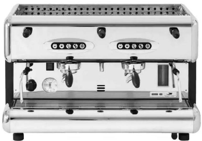
2. Exploded diagrams
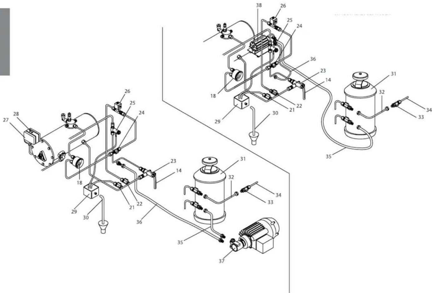
3. Diagram of water feed system

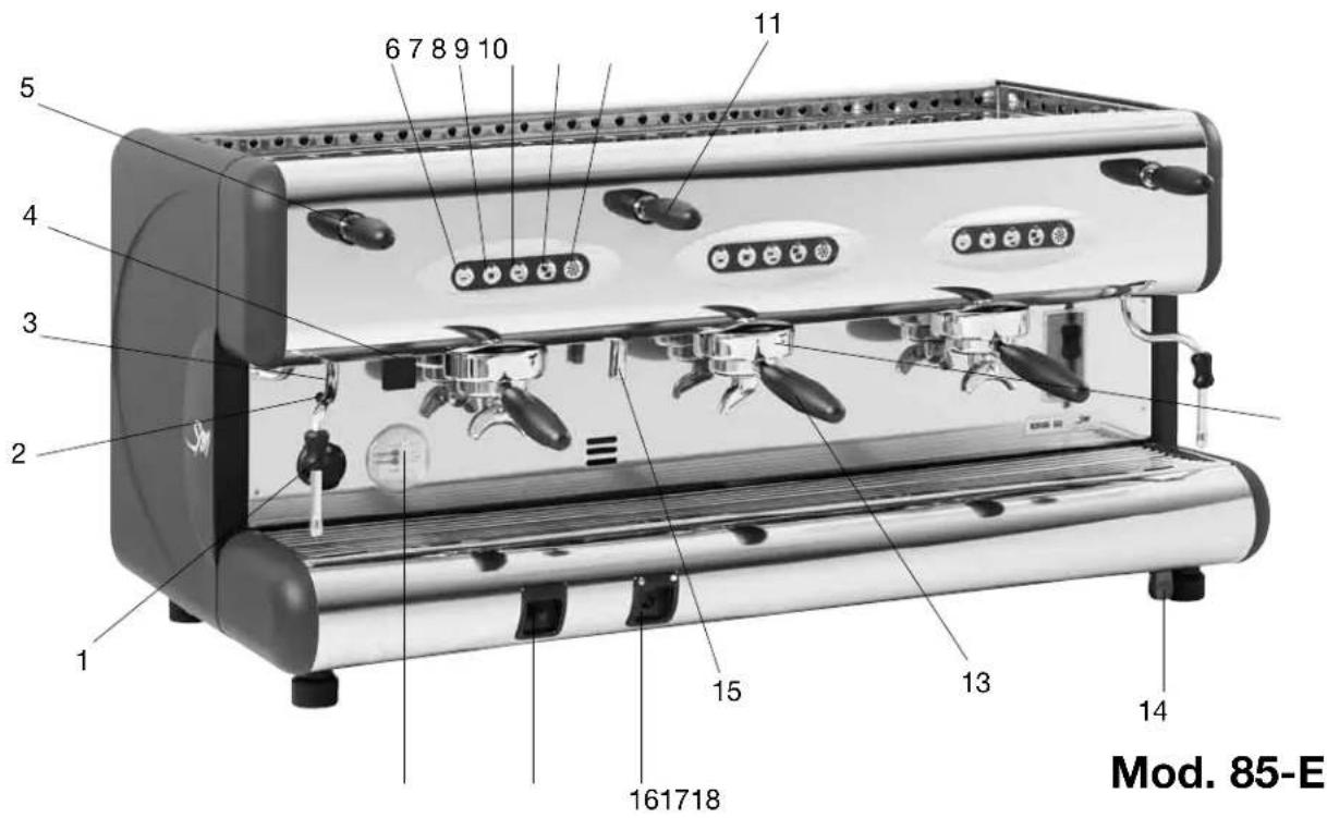
Key to illustrations:
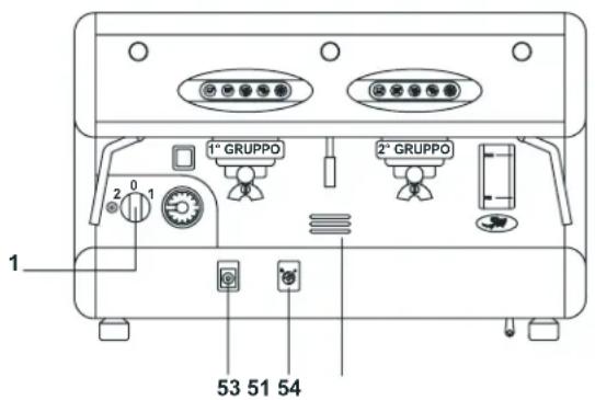
1 Main switch
2 Pilot light
3 Steam spout
4 Cup warmer on/off switch
5 Steam valve lever
6 Button for serving single strong coffee
7 Button for serving single weak coffee
8 Button for serving double strong coffee
9 Button for serving double weak coffee
10 Continuous serving button
11 Hot water valve lever
12 Espresso coffee serving unit
13 Filter holding cup with handle
14 Manual boiler water filling lever
15 Hot water spout
16 Gas burner ignition button
17 Gas burner safety button
18 Two-scale pressure gauge
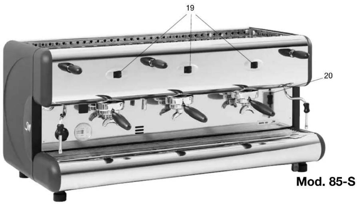
19 Coffee serving button
20 Visual level indicator
21 Boiler water drain tap
22 Automatic level tap
23 Push button valve with check valve
24 Automatic level tap
25 Check and safety valve
26 Automatic level solenoid
27 Pressure switch
28 Pressure switch setting screw
29 Grounds collecting tray
30 Drain pipe
31 Water softener
32 Water softener feeding pipe
33 Mains water supply tap
34 Mains water supply pipe
35 Pump feeding pipe
36 Machine feeding p
37 Pump (external model)
38 Pump (internal model)
4. Technical specifications
| 85 S/E | COFFEE SERVING UNITS | STEAM WANDS | HOT WATER WANDS | BOILER CAPACITY (1) | WEIGHT (KG) | WIDTH (MM) | HEIGHT (MM) | DEPTH (MM) | INSTALLED POWER (W) | ||||
| BOILER HEATINGELEMENT | BUTT-IN MOTORPUMP | EXTERNAL MOTOR-PUMP | CUP HEATER(OPTIONAL) | ||||||||||
| MONO-PHASE | TREE-PHASE | ||||||||||||
| 85 PRACTICAL | 1 | 1 | 1 | 5 | 42 380 | 470 545500 - 7000 | 470 545500 - 7000 | 1750 - 300 - | |||||
| 85 SPRINT | 2 | 56 630 | 3000 4500 | 275 | - | - | |||||||
| 85 SPRINT 10I | 2 70 96 | 0 550 | 10 20 | 800 4200 - - | |||||||||
| 85 2 | 12 60 | 720 3500/4 | 300 | 100 | |||||||||
| 85 3 | 3 19 | /7000 | - 125 | ||||||||||
| 85 4 | 4 | 25 90 | 1200 | 7000 /9000 - 150 | |||||||||
| ACCESSORIES: WATER SOFTENER; MANUAL MIK FROTHER; AUTOMATIC STEAM WAND; CUP HOLDER (FOR MODEIS 2,3,4 GROUP);GAS HEATING (FOR MODEIS 2,3,4 GROUP); EXTERNAI MOTOR-PUMP 300 W (FOR MODEI SPRINT) BUIIT-IN MOTOR-PUMP 275 W FOR MODEIS 2/3/4 GROUPS). | |||||||||||||
5. Installation

- The installation must be carried out by authorized La San Marco technical personnel.
- The coffee machine is delivered in a suitable cardboard and styrofoam packing.
The packing contains the machine and its accessories, the user manual and the conformity declaration.
After opening the packing, check the proper condition of the coffee machine and its components. In case of doubt, do not use the appliance, and contact La San Marco S.p.A. The packing must be disposed of at the proper waste collecting centres, in compliance with local laws. Do not discard in the environment. The packing elements (carton, styrofoam, nylon, staples, etc.) can be a source of hazards. Keep out of reach of children.
- The machine should be placed on a perfectly horizontal plane sufficiently sturdy to support the weight of the machine, with a sufficient clearance around it to dissipate the heat generated during its operation.
5.1 Equipment in machine kit
The machine packing contains the equipment kit, which includes the following items:
- filter cups with filter restraint ring
- filters for filter cups (single and double doses)
- blind filter for filter cup
- spouts for filter cups (single and double doses)
- press for ground coffee
- braided 900mm stainless-steel tube for water connection (water supply - water softener)
- rubber drain hose with steel coil for water drain
- 3 / 8" nipples for hose connection to water supply tube
- cleaning brush for serving units
- pump suction filter (on request)
- braided 600~mm stainless-steel tube for water connection (pump inflow - water softener) - optional only for external pump
- braided 1600mm stainless-steel tube for water connection (pump outflow - coffee machine) - optional only for external pump;
5.2 Prearrangement of water supply
FEEDING LINE
Bring the water feeding tube (of at least 3/8 diameter) up to the machine and install an on-off valve (preferably of 3/8 ball type) that allows a rapid opening and closing operation. The appliance should be connected to the water mains using the tube supplied with it. Do not connect the appliance with used tubes.
DRAIN LINE
Provide an inspeatable drainage pit on the floor connected with the sink drainage line, suitable for receiving the machine gravity drainage tube.
The drain tube must be positioned so that the water flows out freely, without possibility for the pipe to clog up during the operation.
5.3 Water softener (optional)
The water softener for the mains water can be manual or automatic, depending on customer's request.

Before connecting the water softener to the coffee machine, the resins contained in it should be washed off as described in the user's manual supplied with the appliance.
Note:
The water softener is considered an essential device to guarantee a proper operation of the espresso coffee machine. A water softening system should be provided in order to guarantee the efficiency, performance and duration of the components in the machine.
5.4 Installation of the water system
INTERNAL PUMP
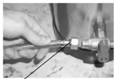
1) Use the braided 900~mm stainless-steel tube 32 to connect the on-off valve of the water supply to the water softener inflow valve (figure 1).
2) Using the rubber-braided 35 stainless-steel tube (2500 mm long), connect the internal pump intake with the water softener valve (figure 2).
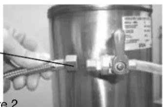
32 35
Figure 1 Figure 2
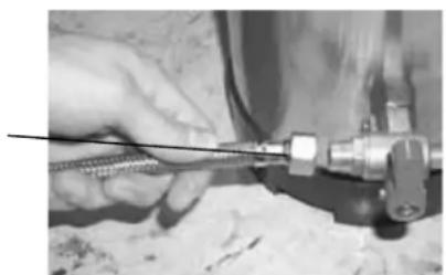
EXTERNAL PUMP
1) Use the braided 900~mm stainless-steel tube 32 to connect the water supply on-off valve to the water softener inflow valve 1 (figure 3).
2) Using the rubber-braided stainless-steel tube 35 (600 mm long), connect the pump intake with the water softener valve (figures 3-4).
3) Using the rubber-braided stainless-steel tube 36 (1600 mm long), connect the pump outflow with the nipple 5 of the water system on the machine (figures 4-5).
35
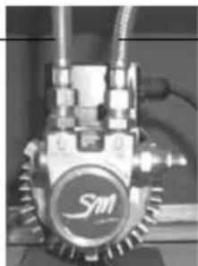
Figure 4 Figure 5
35 36
36
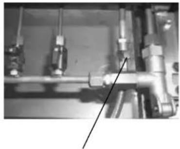
5.5 Drainage
Connect the drainage tube to the grounds collecting tray and to the water drainage system.
5.6 Electrical connections

Instructions for a proper electrical connection of the espresso coffee machine:
Before connecting the machine to the power supply, make sure that the data on the rating tag correspond to the available power supply.
The tag is located on the left side of the machine (and can be accessed by removing the lower tray).
The power connection must be carried out according to applicable requirements.
- The power system prearranged by the customer must comply with the current applicable laws and the power socket must be provided with an efficient grounding system. La San Marco S.p.A. declines any liability if the applicable prescriptions of the law are not complied with. An improper installation can cause injury or damage for which the manufacturer cannot be held liable.
If it is necessary to use adapters, multiple plugs and extensions, only products meeting applicable safety standards must be used.
- To avoid any overheating of the power cable, unwind it completely.
- For the electrical connection, it is necessary to install an omnipolar main switch upstream of the power supply; this switch should be rated according to the electrical characteristics (power and voltage) shown on the rating tag. The omnipolar switch must disconnect the power supply with a contact gap of at least 3mm .
Connect the power cable to the main switch as follows:

| Only fOR 85 1 MODEls | 110V/230V SINGLE PHASE | 1 heATing eleMenT |
| n BLUE BROWN YEL/GREEN | BLUE BROWN YEL/GREEN | |
| Only fOR 85 COMPACT MODEls | 230V SINGLE PHASE 2 heATing eleMenTs | |
| n BLUE BLACK GRAY BROWN YEL/GREEN | BLACK GRAY BROWN GRAY YEL/GREEN | |
| 400V-3N THREE PHASE 3 heATing eleMenTs | ||
| n BLUE BLACK GRAY BROWN YEL/GREEN | BLUE BLACK GRAY BROWN GRAY YEL/GREEN | |
| 230V-3 THREE PHASE 3 heATing eleMenTs | ||
| l3 BLUE BLACK GRAY BROWN YEL/GREEN | BLUE BLACK GRAY BROWN GRAY YEL/GREEN | |
| OTheR MODEls | 230V SINGLE PHASE * 400V-3N THREE PHASE | |
| n BLUE BLACK GRAY BROWN YEL/GREEN | BLUE BLACK GRAY BROWN YEL/GREEN | |
| 230V-3 THREE PHASE | ||
| l3 BLUE BLACK GRAY BROWN YEL/GREEN | BLUE BLACK GRAY BROWN GRAY YEL/GREEN | |
5.7 Connection to the equipotential clamp

The machine is provided with an equipotential clamp placed under the tray and the bottom support cup grid.
The terminal is identified by the equipotential symbol reported here on the side.
Connect only cables of 2.5mm to 6mm with ring lugs for screw M8

The connection to the equipotential clamp must be performed by LA SAN MARCO SPA authorized qualified personnel.
To make the connection remove the bottom tray. On the left side of the frame, indicated by the equipotential symbol, there is the screw-clamp to be used to connect a cable of 2.5mm to 6mm with ring lugs for screw M8.
6. Operating instructions
6.1 Filling the boiler
Checking the position of the taps in the water system
a) Remove the coffee ground collection tray with grille. Now, check for the following configuration:
- Boiler drain tap 21: closed
- Tap on the automatic level control valve 24: open
- Tap on the automatic level control valve 22: open
b) Install the coffee ground collection tray with grille
c) Open the main water fill tap 33
d) Open a steam delivery lever 5 to allow air to escape from the system as the boiler is filled.
Mod. 85 - Practical - S/E
e) Move the main switch 1 to position 1 to fill the boiler automatically without activating the heating elements. When the water reaches the probe, the "MAx" led will light up. When the boiler is full, turn the main switch to working position 2.
Mod. 85 - S/E - 2 - 3 - 4
f) Make sure that the main switch 1 is in position "zero".
g) Press and hold down the button 14 until the sight glass 20 is 3/4 full.
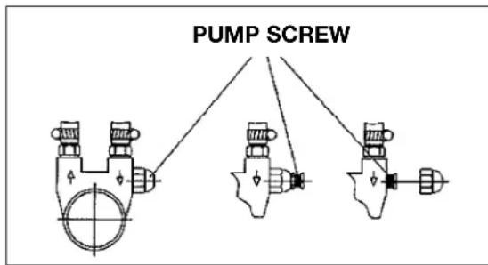
6.2 Calibration of pump pressure
a) Once the boiler is filled, turn the main switch to position 2 (the heating elements start to heat the water).
b) Press the continuous-feeding push button 19 for the manual serving machines or the push button 10 for the electronic machines with automatic serving, so that the water flows out of the unit corresponding to the pressed button.
c) Read the water pressure value on the lower part of the pressure gauge 18. The optimum pressure is 9 bar.
The pressure is adjusted to the desired value by operating on the pump screw: the pressure is increased by turning clockwise; it is decreased by turning counterclockwise. As shown in the following figure, there are three different cases for adjusting this screw, depending on the pump installed on the machine:
- adjust only the screw
- adjust the screw and lock it with the lock nut
- unscrew the cap nut and adjust the screw.
6.3 Calibration of water pressure in the boiler
a) After having filled the boiler to the proper level, turn the main switch to position 2 (the heating elements will start to heat the water).
b) Open the lever-controlled steam valve 5 to vent the air during the heating phase. Close the valve as soon as the steam phase is reached. The steam pressure in the boiler can be read on the upper scale of the pressure gauge 18 from 0 to 3 bar. The pressure rises to the calibration value of the pressure switch 27 in the range from 0.9 to 1.1 bar. To vary the steam pressure, turn the screw 28 on the pressure switch 27. The pressure is decreased by turning the screw clockwise and it is increased by turning the screw counterclockwise. The screw is adjusted by means of a screwdriver inserted into the hole on the lid of the pressure switch. The pressure switch can be reached from the upper tray and grill.
6.4 Heating the water in the boiler
a) Rotate the main switch to position 2.
b) Hold down a steam delivery lever 5 to allow air to escape from the system as the machine heats up. Release the lever as soon as steam escapes from the delivery pipe. Boiler pressure is indicated on the 0-to-3-bar scale on the pressure gauge 18 (suggested value: 0.9-1.2 bar).
6.5 Electric cup warmer (Optional)
The on/off button 4 is used to heat the cup holding shelf; it can be switched on and off at will.
6.6 Steam delivery
This function is used to deliver steam from the boiler to heat liquids, or to foam milk for cappuccinos. Lower or raise the lever 5 to obtain the maximum flow of steam. Move the lever sideways to the left of right to obtain a reduced steam flow.
6.7 Hot water delivery
The lever-operated tap 11 is used to deliver hot water from the boiler for making tea, camomile herb tea, etc. This lever operates in the same way as the steam delivery lever.
6.8 Preparation of ground coffee
Make sure that the filter with the desired capacity has been installed in the filter holder. After the coffee has been loaded and pressed into the filter, the coffee level in the filter must just touch the spray head on the brewing unit. To check for correct coffee level, install the full filter holder onto the brewing unit and then remove the holder. Now, look at the surface of the coffee: if the level is correct, the coffee will contain the imprint of the central mounting screw on the spray head of the brewing unit.
6.9 Brewing coffee
Semiautomatic models: 85 - S
Once the filter holder has been installed onto the machine, simply press the switch 19 to actuate the pump and solenoid valve. When the coffee in the cup has reached the desired level, move the switch back to its original position to terminate brewing.
Automatic models: 85 - E
Once the filter holder has been installed onto the machine, press one of the five brewing buttons. The first two buttons 6 and 7 are used to select the two pre-programmed single portions of coffee. The second two buttons 8 and 9 are used to select the two pre-programmed double portions of coffee. The fifth button 10 immediately shuts down brewing if pressed during a coffee brewing cycle. Button 10 can also be used to brew the desired quantity of coffee manually: press this button to start brewing, and presse the button a second time to stop brewing when the desired quantity of coffee has been obtained.
6.10 Draining the boiler
If the boiler must be emptied, shut off the power to the machine by moving the main switch 1 to the "zero" position. On gas-fired machines, extinguish the flame by closing the gas feed valve. Open the drain tap 21 until the boiler has been completely drained.
Important: be sure to close the tap before refilling the boiler.
6.11 Automatic operation - programming the coffee brewing cycles
Automatic models: 85 - E
A. Entering the programming mode
Set the main switch 1 on the machine to position "zero" (machine switched off).
Hold down the fifth button 10 on the first brewing unit. Now, rotate the main switch 1 to position 1 (machine switched on). After a few seconds, release the button 10. The indicator led for the button will now begin to flash, as will the same led on all the other brewing units. The machine is now ready for programming.
B. Programming
To program the four portions on brewing unit I, proceed as follows: place the single-portion filter into the single-portion filter holder. Use the coffee dispenser to dispense a single portion of coffee into the filter. Mount the filter holder onto brewing unit I.
Place an espresso cup under the spout on the filter holder.
Press the first button 6 whose portion is to be programmed. When the coffee in the cup reaches the desired level, press the fifth button 10 to stop brewing.
Follow the same procedure to program the other portions on each group. Once the four portions on brewing unit I have been programmed as desired, the relative data can be transferred to the other brewing units by pressing the fifth button 10 on each unit. When each button 10 is pressed, the indicator led for the button will stop flashing and remain steadily lit. This shows that the data on brewing unit I has been transferred successfully.
C. Exiting from the programming mode
After you have finished programming the machine, press the button 10 (with flashing led) on brewing unit I and all the leds will turn off. The programmed quantity of coffee will now be delivered when an automatic brewing button is pressed.
6.12 Alarms
A flashing Led on the first button of pushbutton array indicates a malfunction on the flow meter.
A flashing Led on the second button of all the pushbutton arrays indicates a malfunction on the automatic boiler refill system (jammed solenoid valve, insufficient water from the main water system, etc.). After 1'30", the pump motor will shut down.
Note: If the machine shuts down as described above, call your local service technician.

- Do not use water sprays, steam or similar cleaning methods. Before cleaning or maintenance operations, DISCONNECT THE CABLE IF POSSIBLE; OTHERWISE, SHUT OFF THE OMNIPOLAR MASTER SWITCH INSTALLED AHEAD OF THE MACHINE.
- If power cable is damaged, it must be replaced with the specially prepared, original equipment replacement part which conforms to safety regulations.
- Special maintenance, parts replacement, long-term outdown and displanting operations must be performed by LA SAN MARCO service personnel.
7. Instructions for Authorized Installer Gas fired Boiler (Optional)
Read the instructions before installing and using the appliance.

This appliance can only be installed and used in permanently ventilated places according to UNI-CIG 7129 and UNI-CIG 7131 Standards.
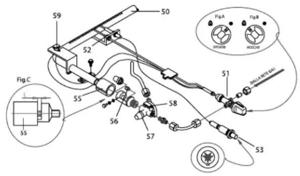
7.1 Connection to gas supply
Position the appliance as described in the Use and Maintenance Manual, remove the control panel as described in the same handbook, and connect the appliance to the gas supply mains, or LPG bottle (G30/G31), using rigid metal pipes or flexible metal tubes according to UNI-CIG 9891 Standards.
Check that the appliance is prearranged for the type of gas actually being used; the corresponding setting is shown on the settings tag.
If the appliance is prearranged for a different type of gas, change the arrangement as described in the paragraph "Changing the calibration".
The gas infeed, consisting of an on-off valve (51), includes a G 1/8" threaded connection (thread is not gastight) according to ISO 228-1 Standard.
If using rigid metal pipes for connection to the gas supply, place an appropriate fitting between the valve and the rigid metal pipe, which should be provided with a G 1/8" female thread (thread is not gas-tight) according to ISO 228-1 Standard.
If using flexible metal tubes for connection to the gas supply, interpose an appropriate G 1/2" female nipple (gas-tight thread) according to ISO 7-1 Standard and a G 1/2" male nipple (thread is not gas-tight) according to ISO 228-1 Standard; interpose a suitable gas-tight gasket.
When the connection is completed, open the gas flow upstream of the appliance and, using a soapy solution (never a free flame), check the perfect tightness of the connection.
7.2 Venting the combustion fumes
In relation to the venting of the combustion fumes, the appliance is of Type A1: i.e., it draws in the air required for combustion from the room and discharges the fumes in the same environment.
Place particular attention to the volume of the room where the appliance is to be installed: this should be at least 12m^3
If the room has a smaller volume, it will be necessary to install the appliance directly under a suction hood, and also to provide a combustion air intake with a free-flow cross section of at least 100cm^2
7.3 Ignition
Press and turn the gas valve knob (51) counterclockwise to the position of the flame symbol, as shown in Fig. B. While holding the knob pressed, push a few times the burner ignition button, marked with the star symbol (53) to ignite the burner (piezoelectric ignition).
When the flame is lit, check through the relative hole (54), while keeping the gas knob pressed for 5-10 seconds. After this period, if the flame does not remain lit, repeat the ignition operation again.
7.4 Changing the calibration
The appliance is prearranged to operate with the gas indicated in the relative settings tag attached to the appliance. The information regarding the air setting, injector, rated and reduced heat flow are shown in Tables 1 and 2. The data that correspond with each model are indicated by the next-to-last character of the code for the relative model. For example, the model code shown on the tag for the gas part characteristic 85-E-3-G shows number 3 in the next-to-last digit.
In this case, refer to the data shown in Tables 1 and 2, respectively, in the column headed "3 Units".
If you wish to change the calibration of the appliance, proceed as follows:
Unscrew the primary air adjusting ring nut (55 - Fig. C) to expose the nozzle (56). Using the relative wrench, unscrew the nozzle (56) and replace it with the proper one indicated in Table 2, checking that the diameter marked on the same nozzle corresponds to the right diameter.
| Table 1 - Adjusting the primary air (Fig. C) | |||
| Gas 2 Units | 3 Units | 4 Units | |
| GPL L = 8 (G30/G31) | mm L = 10 | mm L = 12 | mm |
| Nat. gas (G20) | L = 4 mm L = 4 mm L = 4 mm | ||
| Qn = Rated heat flow Qnr = Reduced rated heat flow | |||
| Table 2 - Nozzle diameters in 100/mm | |||
| Gas 2 Units | 3 Units | 4 Units | |
| GPL (G30/G31) | 40 | 55 | 65 |
| Nat. gas (G20) | 60X | 81X | 90X |
| Qn (kW) | 0,75 | 1,45 | 1,9 |
| Qnr (kW) | N.A. | 1,0 | 1,3 |
Screw on the new nozzle (56), and position the primary air adjusting ring nut (55 - Fig. C) according to the indications of Table 1, using a gauge or equivalent instrument to set the distance "L", and tighten the screw provided to fasten the nozzle.
Turn the main switch (1) to position 1, so as to connect a single heating element (50% of the boiler's electric power for single-phase heating element with 2 elements and 1/3 of power for heating elements with 3 elements with three-phase connection), and ignite the burner as in the procedure described above. When the water contained in the boiler reaches the preset temperature, the gas flow regulator will automatically decrease the flow to the value corresponding to the reduced rated heat flow.
At this point, turn the flow regulation screw (58) so as to have a steady flame licking the sensitive thermocouple element (52), and turn the screw (57) to obtain the maximum desired pressure value in the boiler.
After having verified the proper operation, replace the settings tag on the appliance with the one for the new type of gas that is provided with the standard kit containing the newly installed gas nozzle. Safety devices on appliance (manually reset).
The appliance is provided with two safety devices that shut off the gas flow if the flame accidentally goes out.
1 - Termocouple (52): The thermocouple operates on the valve (51), whose probe (52) must be licked by the flame from the burner (50). If the probe is not enveloped by the flame, the gas flow will be automatically shut off.
2 - Thermostat (59): The thermostat, placed in contact with the boiler, operates on the valve (51); when the thermostat sensor on the boiler reads 140^ , the gas flow will be automatically shut off.
The burner can be re-ignited with the procedure described above only after the boiler body has cooled to 110^ . Following the activation of one of the two safety devices, try re-igniting the burner with the procedure already described.
If the malfunction persists, and the burner consequently continues to go off, contact the nearest authorized Service outlet, which will provide to eliminate the cause of the malfunction.
8. Routine maintenance
-
No panel or fixed guard of the frame may be removed from the machine to carry out the routine maintenance.
-
Do not use harsh or harmful detergents such as alcohol, petrol or solvents to clean the coffee machine; use water and neutral detergents.
Note:
The daily cleaning operations must be carried out in order to maintain the efficiency of the machine and to guarantee the safety of the user and of the persons around it.
8.1 Cleaning the serving units and the filter holder
1) Detach the filter cup from the serving unit, remove the coffee grounds and replace the filter present with the blind filter (without holes) provided with the machine.
Note:
The filter is inserted into the cup by pressure; to remove it, it is sufficient to force it on the sides and then extract it. Do not remove the elastic ring on the inside of the filter holder.
2) Using the brush, clean the seat in the unit in which the filter cup is inserted.
3) Insert the cup in the unit and, without latching it completely, press the continuous flow button.
4) Let water overflow from the filter holder. This will clean the serving group.
The continuous flow of water from the unit can cause burns due to accidental skin contacts.
5) Stop the water flow and insert the filter cup in the unit.
6) Start the continuous flow and then stop it after a couple of seconds; repeat this operation a few times (this is to clean the drain duct and the solenoid of the unit).
7) Clean the perforated filter and place it back into the cup. Let the water flow for a couple of seconds to clean the filter, the cup and the spouts.
8) Repeat these operations on all the serving units.
Note:
Special commercially available detergents can be used to effectively clean the serving units.
8.2 Cleaning the tray and the cup support grill
The lower cup support grill 5 must be kept clean at all times; during the normal use of the machine, it is sufficient to clean it with a sponge or a moist cloth. At the end of the working day, clean the tray and the grill also in the internal areas using warm water and neutral detergent.
8.3 Cleaning the steam spout
Clean the steam spout with a sponge or a moist cloth at the end of the working day to remove all traces of milk or other substances that inevitably form during the normal operation of the machine. Open the steam tap, placing the spout in the tub, to remove any residues which may have accumulated in the spout.
8.4 Substitution of boiler water
To change the water inside the boiler, proceed as follows:
1) Cut off the power supply to the machine by turning the main switch 1 to position 0 (zero).
2) Remove the tub and the cup support grille and open the boiler drain tap.
3) Open a steam drawing valve to facilitate the draining of the water until the end of the operation.
4) When water no longer comes out of the boiler, close the boiler drain and the steam drawing tap.
5) Charge the machine with water following the instructions of paragraph "Charging the water in the boiler".
6) To improve product quality, it is recommended to replace the water in the boiler and to change the water contained in the water circulation pipes when starting the machine every day.
9. Idle periods
If the machine is to remain idle for long periods (weekly closing days, holidays, etc.), take the following precautions:
1) Turn the main switch to 0 (zero) and as necessary disconnect the power cord or the main switch of the electrical mains.
2) Close the cut-off valve of the water mains.
3) If you think the temperature might drop below 5^ , completely drain the water system of the machine.
4) Wash the components of the machine as described in the paragraph on routine maintenance.
5) Cover the machine if necessary.
10. Information for users in the European community
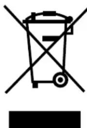
Pursuant to European Directive 2012/19/EU on electrical waste (WEEE), users in the European community are advised of the following.
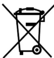
- The symbol with the crossed-out dustbin on the appliance or its packaging indicates that at the end of the product's life cycle, it must be collected separately from other waste.
- Suitable separate collection of the equipment for subsequent recycling, treatment and disposal contributes to preventing possible negative consequences for the environment and health, and favours the recycling of materials that the unit is made of.
- In accordance with European Directive 2012/19/EU, abusive disposal of the product by the user will result in application of penalties as set forth by local law.
11. Guarantee
The warranty becomes void if:
The instructions in this manual are not complied with.
The scheduled maintenance and repairs are carried out by unauthorized personnel.
The machine is used for any other than its intended purposes.
The original parts are replaced with parts from different manufacturers.
- The warranty does not cover damage caused by neglect, use and installation not in compliance with the recommendations of this manual, improper operation, abuse, lightning and atmospheric phenomena, overvoltage, overcurrent, or insufficient or irregular power supply.
12. Declaration of conformity (€
The manufacturer:
La San Marco S.p.A.

declares under its own responsibility that the ESPRESSO COFFEE MACHINE (as identified by the data on the tag located on the machine) is complaint with the following European directives: 2006/42/EC, 2006/95/ EC, 2004/108/ EC, Regulation (EC) no. 1935/2004, 2012/19/EU, 2011/65/EU.
For verification of compliance with said directives, the following harmonized standards have been applied: EN ISO 12100, EN 60335-1, EN 60335-2-75.
AUTHORISED PERSON A
COMPILE THE TECHNICAL FILE
Mr Roberto Nocera
Mr Roberto Nocera C.E.O.

Gradisca d'lsonzo, November 2015
13. Problem solving
| PROBLEM CAUSE | SOLUTION | ||
| 1. | The boiler is full of water and the water flows out of the safety valve. | • One of the outflow lines the boiler or from a circuit of the unit has a leak. | • Check the autolevel circuit, the manual charging button, and the boiler heat exchangers. • Replace worn or damaged parts to eliminate the leak. |
| 2. | The safety valve trips in and vents the steam. | • Malfunction of electrical system (the electrical heating element is always connected). • Pressure increase in the boiler (the safety valve trips in at 1.9-2.5 bar). | • Check the wiring that feeds the heating element and the pressure switch. • In the machines with electronic temperature control, check the proper operation of the electronic control unit, the triac, the level probe, and the electrical wiring. |
| 3. | The machine was started properly but the water in the boiler does not warm up. | • The electric heating element is defective or is not connected. | • Check if the heating element is connected to the power supply. • Check if the heating element thermostat has tripped in and check its proper operation. • In the machines with electronic temperature control, check the proper operation of the electronic control unit, the triac, the level probe, and the electrical wiring. |
| 4. | There is no water flowing from a serving unit. | • Coffee ground too fine excessive quantity for type of filter used. • Clogged water circuit. • Defective solenoid. | • Adjust the grinding coarseness or the quantity of ground coffee. • Check that the injector, the upper circulation tube, the spray nozzle and the solenoid of the unit are not clogged. • In the machines with electronic metering, check the displacement meter and its valves. • Check the solenoid of the unit, its wiring and the fuse in the electronic control unit. |
| 5. | The programmed servings of espresso coffee are not constant or vary on the different units. | • Abnormal operation of the electronic control unit or of the displacement counters. • Leak from serving unit solenoid valve. | • Program the serving quantities separately on each serving unit. If the problem persists, replace the displacement meter of the serving unit affected. • Replace the solenoid valve of the serving unit. |
| 6. | It is not possible to program the serving quantities on unit 1 and to copy them on the other units. | • Abnormal operation or defective displacement meter of unit 1. | • Check the control unit-displacement meters electrical wiring. • Replace the displacement meter. |
| 7. | Displacement meters alarm. | • Displacement meters jammed or defective. • Defective wiring. | • Replace the displacement meter. • Check the wiring and its connections, the control unit and the fuses. |
| 8. | Autolevel alarm. | • Lack of water in the circuit. • Main water supply valve closed. • Faulty autolevel solenoid. | • Replace the hydraulic circuit of the autolevel. • Check if the on-off valve on the water supply is open. • Replace the autolevel solenoid. |
| 9. | The machine is switched on (the main switch is in position 1 or 2 and the signal light is lit) but the electronic control is out of order. | • The electric wiring of the electronic control unit is defective. • The electronic control unit defective. | • Check the electrical wiring, the electronic control unit and its components. • Replace the electronic control unit. |
| PROBLEM CAUse s | OILUTiOn | ||
| 10. | The machine feeds water from one serving unit although the serving has not been selected. | ·Solenoid and/or pump fed continuously. | ·Short-circuited control unit relay. ·Replace the electronic control unit. |
| 11. | 85 S models: one unit serves water continuously. | ·Electric circuit of unit internally connected. | ·Check the connection and correct it (see wiring diagram). |
| 12. | The steamer discharges only small quantities of steam or water droplets. | ·Worn gasket on tap. | ·Replace the gasket. |
| 13. | Small drops flow out of the water tap. | ·Worn gasket on tap. ·Leak from solenoid. | ·Replace the gasket. ·Check the solenoid and if necessary replace it. |
| 14. | The unit emits a whistle after serving the coffee. | ·Faulty operation of expand valve. ·High pump pressure. | ·Check the expansion valve and necessary replace it. Calibrate the valve at 12 bar. ·Check the pump operating pressure. Calibrate the pump at 9 bar. |
| 15. | The filter cup comes off the serving unit. | ·Worn gasket under the cup. | ·Replace the gasket. ·Clean the serving unit and the filter cup. |
| 16. | When coffee is being served, some of it drips out of the edge of the filter cup. | ·Worn gasket under the cup. | ·Replace the gasket. ·Clean the serving unit and the cup. |
| 17. | Water leaking from the drain of the serving unit solenoid. | ·Malfunctioning unit solenoid. ·Water leaking from unit cooling system. | ·Check the unit solenoid. ·Check the plunger on the solenoid and clean the solenoid. ·Replace the solenoid. ·Check the cooling tube and the seal rings inside the unit. |
| 18. | Light cream (the coffee flows out of the spout rapidly). | a. Coarse grinding. b. Low pressing pressure. c. Small quantity of ground coffeep. d. Water temperature below 90°C. e. Pump pressure above 9 bar. f. Sprinkler filter on unit clogged. g. Filter holes widened (filter cup). | a. Finer grinding. b. Increase the pressure. c. Increase the quantity of ground coffee. d. Increase the pressure in the boiler. e. Decrease the pump pressure. f. Check and clean with blind filter or replace. g. Check and replace the filter. |
| 19. | Dark cream (the coffee drips out of the spout). | a. Fine grinding. b. High pressing pressure. c. Large quantity of ground coffee. d. High percolation water temperature. e. Pump pressure below 9 bar. f. Sprinkler filter on unit clogged. g. Filter holes clogged (filter cup). | a. Coarser grinding. b. Reduce the pressure. c. Decrease the quantity of ground coffee. d. Decrease the boiler pressure. e. Increase the pump pressure. f. Check and clean with blind filter or replace. g. Check and replace the filter. |
| 20. | Presence of grounds in coffee cup. | a. Coffee ground too fine. b. Worn grinders in grinder-dispenser unit. c. Pump pressure above 9 bar. d. Sprinkler filter on unit clogged. e. Filter holes widened (filter cup). | a. Coarser grinding. b. Replace the grinders. c. Decrease the pump pressure. d. Check and clean with blind filter or replace. e. Check and replace filter. |
| 21. | Coffee with too little cream in cup (spurts out of spout). | ·Sprinkler filter on unit clogged. | ·Check and clean with blind filter or replace. |
| 22. | The cream in the cup is too thin (it disappears after a few seconds). | ·Coffee extraction takes a long time due to clogged filter. ·Coffee extraction too fast due to clogged sprinkler filter. ·Water temperature too high. | ·Clean or replace the filter. ·Clean or replace the sprinkler filter. ·Lower the temperature in the boiler. |
| 23. | Presence of depressions in the coffee grounds (looking inside the filter cup). | ·Sprinkler filter partly clogged. ·Low amount of ground coffee for the filter used. | ·Clean or replace the sprinkler filter. ·Adjust the amount of ground coffee. |
Note: If it is not possible to solve the problem as described above, or if other malfunctions develop, contact the authorized La San Marco service centre.
ManUEL D'UTiLisaTiOn ET D'EnTrETiEn sÉriE 85 / s-E
5.4 Montage installation hydraulique
POMPE INTERNE
m = 311
Gradisca d'Isonzo, November 2015
ELABORAR O MANUAL TECNICO
Eng. Roberto Nocera
Eng. Roberto Nocera C.E.O.

6.8 EKKENΩΣH NEPOY MNOIΛEP
Av EeTe va EKevwOeTo uolAep, EaokyTe To peuMa TnC uXavns (NepiotpeovTAC To Yevko diakontn 1 ot n ean "mDv") kai, av n uXavn Lteoupyei e aepio, oBnote tn foLoya, KLeivovTAC To diakontn Tpoopodooiac Upaepiou. AvoiTe Tn Bava EKKevwoonc (21) kai apnoTe Tnv aovxtn Ewoc otou abiaoe I EvTeAowc.
Pooox: Eaavakxieot n 6ava otav eAeAoTe va EaayepoTo poiIep.