
Top 85 - Coffee machine La San Marco - Free user manual and instructions
Find the device manual for free Top 85 La San Marco in PDF.
| Product type | Professional espresso machine |
| Brand | La San Marco |
| Model | Top 85 |
| Number of brewing groups | 2 (base model; 2, 3, or 4 group versions available) |
| Boiler capacity | 12 L |
| Net weight | 60 kg |
| Dimensions (W x H x D) | 72 x 47 x 54.5 cm |
| Power supply | 230 V single-phase or 400 V three-phase (depending on configuration) |
| Power consumption | 3500 W (single-phase) / 4500 W (three-phase) |
| Pump pressure | Adjustable, optimal at 9 bars |
| Maximum steam pressure | 2-2.5 bars (safety valve) |
| Boiler temperature range | 80°C to 128°C (adjustable) |
| Main functions | Espresso brewing, steam for milk, hot water for infusions |
| Available programming | Coffee doses (4 per group), pre-infusion, automatic on/off, day off, RGB LED lighting |
| Automatic washing system | Yes, for the brewing groups |
| Safety features | Manual reset safety thermostat, safety valve (2-2.5 bars), backflow protection, level and temperature alarms |
| Recommended maintenance | Daily cleaning of groups, portafilter, steam wand; daily boiler water change; water softener use recommended |
| Available options | Water softener, electric cup warmer, RGB LED lighting, external pump motor 300 W |
| Warranty | 12 months (parts); labor not included |
Frequently Asked Questions - Top 85 La San Marco
User questions about Top 85 La San Marco
0 question about this device. Answer the ones you know or ask your own.
Ask a new question about this device
Download the instructions for your Coffee machine in PDF format for free! Find your manual Top 85 - La San Marco and take your electronic device back in hand. On this page are published all the documents necessary for the use of your device. Top 85 by La San Marco.
USER MANUAL Top 85 La San Marco
Espresso coffee machines since 1920
Translation of the original instructions
Index
1. Introduction 40
1.1 Using the manual.. 40
1.2Warnings .40
1.2.1 Installation - warnings.. 40
1.2.2 Use of the machine - warnings.. 40
1.2.3 Maintenance - warnings.. 41
1.3 Starting the coffee machine. 42
1.4 Technical characteristics . 42
2. Description of the machine.. 43
2.1 General water system diagram . 44
2.2 Water system diagram key: . 45
3. Installation. pag. 46
3.1 Equipment provided.. 46
3.2 Water mains set-up . 46
3.3 Water softener (optional) . 46
3.4 Installation of water system 47
3.5 Drain line . 47
3.6 Electrical connection . 47
3.7 Connection to the equipotential clamp . 48
4. Start-up. pag. 49
4.1 Charging the water in the boiler. 49
5. Adjustments.. 49
5.1 Adjustment of the boiler water level probe . . . . . . . . . . . . . . . . . . . . . . . . . . . . . . . . . . . . . . . . . . . . . . . . . . .
5.2 Calibration of pump pressure . 50
5.3 Adjustment of steam pressure in boiler.. 50
5.4 Adjustment of temperature of dispenser groups.. .pag. 50
5.5 Additional notes for models TOP 85 DTC (Dual Temperature Control) . . . . . . . . . . . . . . . . . . . . . . . . . . . . . . . . . .
6. Operating instructions.. .51
6.1 Serving of espresso coffee . 51
6.2 Drawing steam.. .52
6.3 Hot water outlet. 52
6.4 Automatic washing system . 53
6.5 Cup heater (optional) . 53
7. Using the display keyboard . 53
8.1 Menu access . 54
8.2 Programming the doses.. .55
8.3 Programming the boiler temperature.. .56
8.4 Date/time programming . 56
8.5 Programming automatic on/off . 56
8.6 Programming day off. 57
8.7 LED RGB cup tray lighting programming . 57
9. Counter reading.. 58
9.1 Read total litres count . 58
9.2 Letture conteggio caffe totali. pag. 58
9.3 Read partial and total single coffee dose count . . . . . . . . . . . . . . . . . . . . . . . . . . . . . . . . . . . . . . . . . . . . . . . . . . . . . . . . .
10. Technical level programming.. .59
10.1 Software information screen . 59
10.2 Infuser . 59
10.3 Language selection screen . 59
10.4 Display message screen . 59
10.5 Service number setting screen . 60
10.6 Dose change activation screen . 60
10.7 Continuous dose activation screen . 60
10.8 LED RGB cup tray lighting activation screen. pag. 60
10.9 Preinfusion activation screen.. 61
10.10 Single dose preinfusion screen . 61
10.12 Water softener filter change signal. 62
10.13 Dose deviation screen . 62
10.14 Lower counter alarm limit screen. pag. 62
10.15 Water counter screen.. 63
10.16 Default setting reset screen . 63
11. Alarm signals.. 63
11.1 Faulty counter screen . 63
11.2 Water softener filter replacement screen.. 63
11.3 Technical service signalling screen . 64
11.4 Boiler water level alarm signalling screen . 64
11.5 Boiler temperature alarm signalling screen . 64
11.6 Check grinding/dose signalling screen . 64
11.7 Possible water leak signalling screen . 65
11.8 Volumetric counter alarm.. 65
11.9 Autolevel alarm . 65
11.10 Maximum water level in boiler alarm . 65
11.11 Alarm for temperature sensor . 65
12. Routine maintenance.. 66
12.1 Cleaning the serving units and the filter holder . 66
12.2 Cleaning the tray and the cup support grill . 66
12.3 Cleaning the steam spout 66
12.4 Substitution of boiler water . 67
13. Idle periods.. 67
14. Safety devices . 67
14.1 Manual reset safety thermostat . 67
14.2 Safety valve . 67
15. Information for users in the european community.. . 67
16. General warranty conditions . 68
17. Declaration of conformity C E .pag. 68
18. Problem solving.. .69
1. Introduction

Before using the machine, carefully read all of the instructions contained in this machine.
1.1 Using the manual

This manual contains all information required for the installation, use and maintenance of the coffee machine.
This manual is an integral part of the machine; always keep it intact together with the appliance.
1.2Warnings

Do not operate the machine or carry out routine maintenance before reading this manual La San Marco S.p.A. reserves the right to make any technical changes on the machine considered necessary without advance notice.
1.2.1 Installation - warnings
The installation must be carried out by authorized La San Marco technical personnel.
- This machine must be installed only in places where its use and its maintenance are made by trained personnel.
- The coffee machine is delivered in a suitable packing. The packing contains the machine and its accessories, the user manual and the conformity declaration. After opening the packing, check the proper condition of the coffee machine and its components. In case of doubt, do not use the appliance, and contact La San Marco S.p.A.
All of the packaging must be carefully conserved in case the machine needs to be transported in the future.
- The machine should be placed on a perfectly horizontal plane at a height of not less than 800mm above the floor. The horizontal plane must be sufficiently sturdy to support the weight of the machine, with a sufficient clearance around it to dissipate the heat generated during its operation.
- The device must be connected to the local water mains using a flexible pipe fitting in compliance with national standards, if these are applicable. Furthermore, the equipment must be installed with suitable "reflux protection" in order to comply with the applicable national and local regulations.
- Connect the appliance to the water main supply using only the equipment provided.
- Do not install the espresso coffee machine in places where cleaning is likely to be carried out with jets of water.
- For safety against hazards related to electrical currents, keep the machine away from sinks, tubs, aquar
uums, taps, and areas that are wet or where water may splash.
- The machine creates heat. Therefore it needs to be placed in a room that is sufficiently ventilated to ensure heat dissipation.
- Keep the machine away from sources of direct heat.
- Make sure that the voltage of the power socket does not differ from that indicated on the technical data and on the identification tag on the machine. If the voltage is different, do not connect the machine. This may be dangerous and may damage the unit.
The electrical connection must be carried out in accordance with the regulations of the country of installation.
1.2.2 Use of the machine - warnings
- The machine must never be switched on before connecting it to the water supply. The user must make sure that the water supply valve remains open when the machine is switched on.
This machine is designed and built for serving espresso coffee, hot water (for the preparation of beverages and infusions) and steam (used to heat liquids). The use of the machine for any other than its intended purposes is considered to be improper and unauthorized. The manufacturer declines any liability for damage resulting from the improper use of the machine. -
The user must be a responsible adult, who is expected to comply with local safety rules and accepted common sense procedures. For a proper and safe use of the machine, the operator must always comply with applicable accident prevention and other work safety and health regulations.
-
This appliance is not designed for use by persons (including children) with limited physical, sensory or mental abilities, or lacking in experience and knowledge, unless they are controlled and taught to use the appliance by a person responsible for their safety. Children must be supervised to make sure they do not play with the appliance.
- Do not immerge the unit in water to clean it.
- Place only empty cups in the cup holding shelf.
The machine in operation must never be covered, as there must be a proper air circulation around it. - The machine must never be used with the fixed and/or mobile guards removed or with the safety devices cut off. The safety devices must absolutely never be removed or tampered with. The panels covering the machine must not be removed, as the machine contains live parts (there is the risk of electric shock).
- When cleaning the machine, avoid using products such as alcohol, petrol or solvents in general; use water or neutral detergents.
- To clean the machine frame, it is sufficient to use a moist cloth or a sponge. Avoid using abrasive products that could damage the elements on the body. To clean the coffee serving units, the filter-holding cups, the grills and the trays, follow the instructions of the Routine Maintenance chapter.
- For better product quality, replace the hot water in the boiler and circulate the water in the pipes upon first turning the machine on in the morning. If the machine is expected to remain idle for a few hours during the day, we also recommend changing the water by running it through the hot water tap and the coffee serving units.
- Don't use the lever of a dispensing unit if the brakes don't work in right way as indicated in the next maintenance points.
1.2.3 Maintenance - warnings
- Strict compliance with the routine maintenance instructions of this manual is required for a safe and efficient operation of the appliance.
The use of the appliance and the routine maintenance and cleaning operations may only be carried out by authorized personnel, under the responsibility of the client.
The scheduled maintenance and repair should only be performed by authorized and qualified personnel. - Check for proper operation of the lever braking system. Lower the lever completely and allow it to return to the initial position, the return time should not be less than 2 seconds. In case of too fast return of the lever to the initial position, contacts an authorized and qualified personnel to restore the braking function properly.
- Before carrying out any machine cleaning or maintenance operations, unplug the power cable, if possible, or disconnect the omnipolar switch upstream of the machine.
- Don't clean the appliance with a jet of water.
If the power cord is damaged its replacement should be performed only by authorized and qualified personnel. - The safety devices must always be in a perfectly efficient state, as regularly maintained by the authorized La San Marco service personnel.
- The hot parts of the machine (serving units, boiler, piping, etc.) can cause serious burns due to accidental contact with the skin. It is therefore necessary to use safety gloves, aprons, etc., during maintenance or repair operations.
- In case of malfunctions or failure of any machine component, contact the authorized service centre and request original La San Marco spare parts. The use of any other than original spare parts voids the conformity certifications and the warranty that accompany the machine.
Any changes carried out on the machine and/or failure to carry out the scheduled maintenance will release the Manufacturer from any liability for any resulting damages and voids the conformity declaration and the warranty. - Unauthorised operations or operations whose methods of execution are not exactly clear or unauthorised interventions on the machine are strictly prohibited; contact the manufacturer for any information, spare parts or accessories that you may need.
- Should the appliance be moved outdoors or to premises where the temperature might drop below 0ircC , it is vital that the exchangers circuit be emptied, cutting off the water supply to the appliance and draining all water from the units until they only emit steam. Omitting to perform this procedure could lead to the exchangers breaking, due to the water inside them freezing.
- For a proper disposal of the machine when it is to be discarded, contact the supplier or the authorized firms specialized in the collection and disposal of solid urban waste. Do not discard the appliance in the environment.
1.3 Starting the coffee machine
Ambient temperature: 5 ÷ 45irc C (drain the water system in case of frost)
Water pressure: 80 ÷ 900 kPa (0.8 ÷ 9.0 bar)
Water hardness: between 5irc f and 9irc f
Noise level emitted by the machine: The weighted sound pressure level A is below 70 db(A), under normal conditions of use of the machine.
The device must be connected to a public low voltage distribution network with a rated voltage of 230V line-neutral (or 400V line-line) and a maximum network impedance of Z = 0.03Ω for TOP 85 3N models (three-phase) and Z = 0.04Ω for TOP 85 1N models (single-phase).
1.4 Technical characteristics
| TOP 85 | COFFEE SERVING UNITS COFFEE SERVING UNITS DTC (OPTIONAL) | STEW WANDS | HOT WATER WANDS | BOILER CAPACITY (L) | WEIGHT (KG) | WIDTH (CM) | HEIGHT (CM) | DEPTH (CM) | INSTALLED POWER (W) | ||||||
| BOILER HEATING ELEMENT | BUILT-IN MOTOR PUMP | EXTERNAL MOTOR- PUMP | CUP HEATER (OPTIONAL) | ||||||||||||
| MONO-PHASE | TREE-PHASE | ||||||||||||||
| TOP 85 SPRINT | 2 - 1 1 5 | 56 63 | 47 54,5 | 3000 | 4500 | 275 - | - | ||||||||
| TOP 85 SPRINT 10L | 2 - 1 10 | 56 63 | 47 54,5 | 2800 | 4200 | 275 - | - | ||||||||
| TOP 85 2 | 2 | 2 | 2 | 1 | 12 | 60 | 72 | 47 | 54,5 | 3500/4500 | Opt. | 300 | 100 | ||
| TOP 85 3 | 3 | 3 | 2 | 1 | 19 | 74 | 96 | 47 | 54,5 | 5500/7000 | Opt. | 300 | 125 | ||
| TOP 85 4 | 4 | 4 | 2 | 1 | 25 | 90 | 120 | 47 | 54,5 | 7000 | 7000/9000 | Opt. | 300 | 150 | |
| OPTIONAL: WATER SOFTENER; MANUAL MILK FROther; AUTOMATIC STEAM WAND; CUP HOLDER (FOR MODELS 2/3/4 GROUPS); EXTERNAL MOTOR-PUMP 300 W (MO- DEL SPRINT); BUILT-IN MOTOR PUMP 275 W (FOR MODELS 2/3/4 GROUPS); ELECTRIC CUP WARMER (2/3/4 GR.); WORK SURFACE LIGHTING LED TECHNOLOGY. | |||||||||||||||
2. Description of the machine
Note: The terms used in this description will commonly be used throughout the following pages.
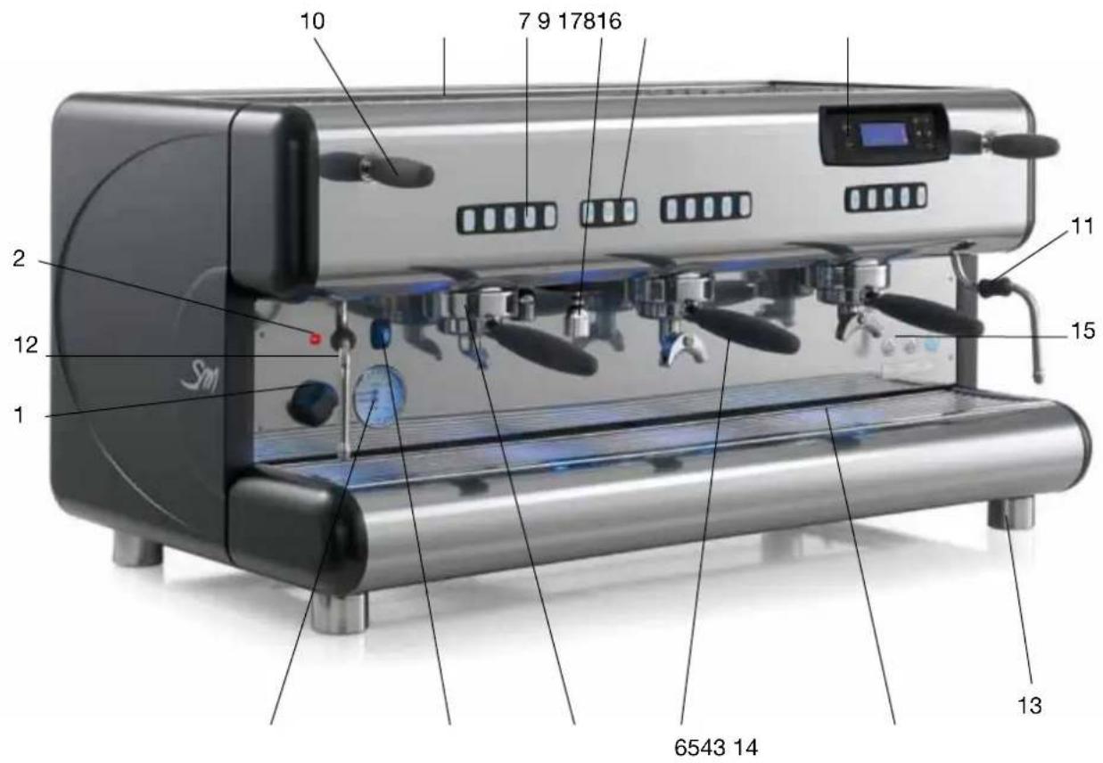
LEGENDA:
1) Main switch
2) Main switch indicator light
3) Double-scale pressure gauge
4) Cup heater switch (optional)
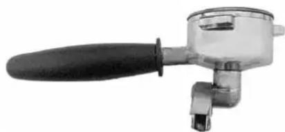
5) Espresso coffee serving unit
6) Filter cup with handle
7) Serving unit push button panel
8) Hot water dispensing keypad
9) Hot water spout
10) Lever of tap for drawing steam
11) Burn protection sheath
12) Steam spout
13) Foot
14) Tray and cup support grill
15) Electronic level
16) Upper cup support tray
17) Display with programming keyboard
2.1 General water system diagram
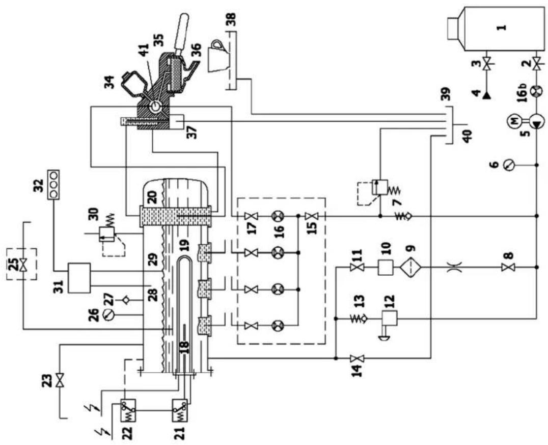
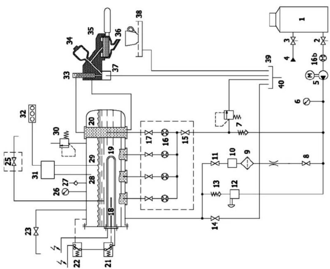
Models TOP 85 Models TOP 85 DTC
2.2 Water system diagram key:
1) Water softener
2) Water softener outflow valve
3) Water softener inflow valve
4) Supply from water mains
5) Electric motor pump
6) Pressure gauge
7) Non-return and safety valve
8) Automatic level control valve
9) Filter
10) Automatic level solenoid valve
11) Automatic level control valve
12) Manual boiler water load valve
13) Non-return valve
14) Boiler water drain valve
15) Volume counter manifold cock
16) Coffee volume counters
16b) Water load volume counter (optional)
17) Exchanger tap
18) Safety thermostat probe
19) Electric heating element
20) Heat exchanger
21) Safety thermostat
22) Temperature probe
23) Steam valve
24)
25) Hot water outlet solenoid valve
26) Pressure gauge
27) Vacuum valve
28) Maximum level probe
29) Level probe
30) Boiler Safety valve
31) Electronic control unit
32) Electronic level signaller
33) Brewing unit temperature adjustment (not available for TOP85 models version DTC)
34) Infusion device
35) Dispensing unit
36) Filter cup
37) Dispensing unit solenoid valve
38) Tray and cup support grille
39) Drain tray
40) Drain tube
41) Cooling tube (TOP 85 version DTC)
3. Installation

The installation must be carried out by authorized La San Marco technical personnel.
- The coffee machine is delivered in a suitable packing. The packing contains the machine and its accessories, the user manual and the conformity declaration. After opening the packing, check the proper condition of the coffee machine and its components. In case of doubt, do not use the appliance, and contact La San Marco S.p.A.
- All of the packaging must be carefully conserved in case the machine needs to be transported in the future.
- The machine should be placed on a perfectly horizontal plane sufficiently sturdy to support the weight of the machine, with a sufficient clearance around it to dissipate the heat generated during its operation.
- For safety against hazards related to electrical currents, keep the machine away from sinks, tubs, aquariums, taps, and areas that are wet or where water may splash.
- The machine creates heat. Therefore it needs to be placed in a room that is sufficiently ventilated to ensure heat dissipation. Keep the machine away from sources of direct heat.
-
Make sure that the voltage of the power socket does not differ from that indicated on the technical data and on the identification tag on the machine. If the voltage is different, do not connect the machine. This may be dangerous and may damage the unit.
-
If the voltage is found to be different, do not connect the machine as this could be dangerous and could damage the device.
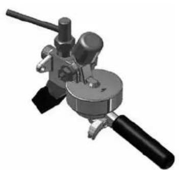
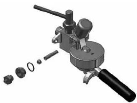
3.1 Equipment provided
The machine packing contains the equipment kit, which includes the following items:
- filter cups with filter restraint ring
- filters for filter cups (single and double doses)
blank filter holder cup for machine cleaning - spouts for filter cups (single and double doses)
- press for ground coffee
- rubber tube with stainless steel mesh for water connection (water circuit - water softener)
- rubber drain hose with steel coil for water drain
- 3/8” nipples for hose connection to water supply tube
- cleaning brush for serving units
3.2 Water mains set-up
FEEDING LINE
Bring the water feeding tube (of at least 3/8 diameter) up to the machine and install an on-off valve (preferably of 3/8 ball type) that allows a rapid opening and closing operation.
DRAIN LINE
The appliance must be connected to the water mains by a suitable coupling, as shown in section 3.4 "Installation of water system", in compliance with national standards where these are applicable.
Provide an inspeatable drainage pit on the floor connected with the sink drainage line, suitable for receiving the machine gravity drainage tube. The drain tube must be positioned so that the water flows out freely, without possibility for the pipe to clog up during the operation.
3.3 Water softener (optional)

The water softener for softening the mains water can be manual or automatic, depending on customer's request.

Before connecting the water softener to the coffee machine, the resins contained in it should be washed off as described in the user's manual supplied with the appliance.
Note:
The water softener is considered an essential device to guarantee a proper operation of the espresso coffee machine. A water softening system should be provided in order to guarantee the efficiency, performance and duration of the components in the machine.
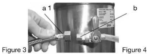
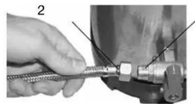
3.4 Installation of water system
INTERNAL PUMP (OPTIONAL)
1) Use the pipe a (900 mm, provided with the machine) to connect the cut-off valve of the mains to the tap 1 for water inlet to the water softener (figure 3).
2) Connect the pipe b for internal pump suction to the tap 2 of the water softener (figure 4).
EXTERNAL PUMP
1) Use the pipe a (900 mm, provided with the machine) to connect the cut-off valve of the mains to the tap 1 for water inlet to the water softener (figure 5).
2) Connect pipe c (600 mm, provided with the external pump) to the pump suction with tap 2 of the water softener (figures 6-7).
3) Connect pipe d (of the water system of the coffee machine) to the pump delivery (figure 7).
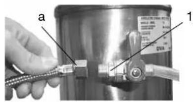
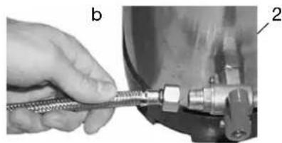
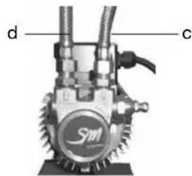
Figure 5 Figure 6 Figure 7
3.5 Drain line
Connect the drainage tube to the grounds collecting tray and to the water drainage system.
3.6 Electrical connection

Instructions for a proper electrical connection of the espresso coffee machine:
-
Before connecting the unit to the electrical mains, make sure that the data on the data plate corresponds to the electrical mains.
-
The tag is located on the left side of the machine (and can be accessed by removing the lower tray).
- The electrical system provided by the client must comply with current standards. The power socket must be equipped with a working earth connection. LA SAN MARCO SPA will not in any way be held liable if legal requirements are not met. An improper installation can cause injury or damage for which the manufacturer cannot be held liable.
For the electrical connection, it is necessary to install an omnipolar main switch upstream of the power supply; this switch should be rated according to the electrical characteristics (power and voltage) shown on the rating tag. The omnipolar switch must disconnect the power supply with a contact gap of at least 3mm .
If it is necessary to use adapters, multiple plugs and extensions, only products meeting applicable safety standards must be used. - To avoid any overheating of the power cable, unwind it completely.
Connect the power cord to the electrical mains as shown in the attached diagram:
| ONLY FOR MODELS TOP 85 SPRINT | 230V MONO-PHASE N BLACK GREY BROWN YE/GR | 2 HEATING ELEMENTS BLACK GREY BROWN BLUE YE/GR |
| 400V-3 TRI-PHASE N BLACK L3 GREY BROWN L1 YE/GR | 3 HEATING ELEMENTS BLACK GREY BROWN GREY YE/GR | |
| 230V-3 TRI-PHASE L3 BLACK GREY BROWN L1 YE/GR | 3 HEATING ELEMENTS BLACK GREY BROWN GREY YE/GR | |
| REMAINING MODELS NOTES: * The power absorbed by the electric heating elements can be reduced to 2/3 by eliminating one of the black wires. | 230V MONO-PHASE* 400V-3N TRI-PHASE N BLACK GREY BROWN YE/GR | 3 HEATING ELEMENTS BLACK GREY BROWN GREY YE/GR |
| 230V-3 TRI-PHASE L3 BLACK GREY BROWN L1 YE/GR | 3 HEATING ELEMENTS BLACK GREY BROWN GREY YE/GR |
3.7 Connection to the equipotential clamp

The machine is provided with an equipotential clamp placed under the tray and the bottom support cup grid.
The terminal is identified by the equipotential symbol reported here on the side.
Connect only cables of 2.5mm to 6mm with ring lugs for screw M8

The connection to the equipotential clamp must be performed by LA SAN MARCO SPA authorized qualified personnel.
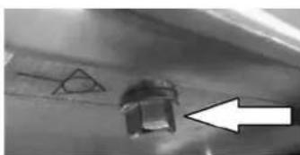
To make the connection remove the bottom tray. On the left side of the frame, indicated by the equipotential symbol, there is the screw-clamp to be used to connect a cable of 2.5mm to 6mm with ring lugs for screw M8.
4. Start-up

-
The coffee machine must be started by qualified technical personnel approved by La San Marco.
-
Once the electric and hydraulic connections are completed, the user is urged to start the espresso coffee machine with the following procedure in order to avoid damaging the appliance.
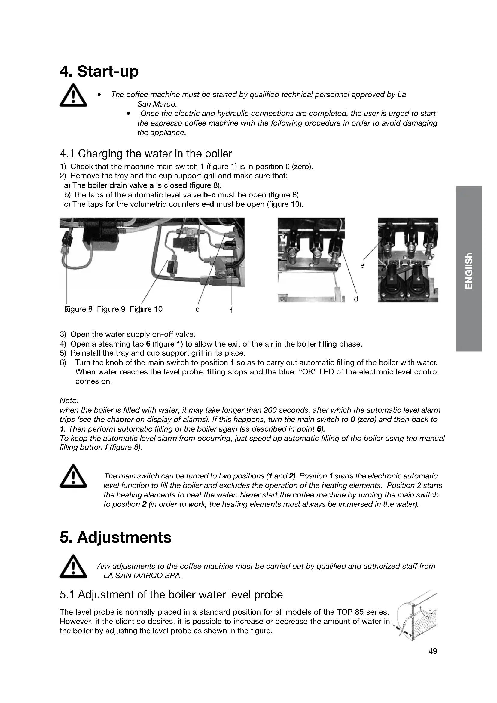
4.1 Charging the water in the boiler
1) Check that the machine main switch 1 (figure 1) is in position 0 (zero).
2) Remove the tray and the cup support grill and make sure that:
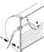
a) The boiler drain valve a is closed (figure 8).
b) The taps of the automatic level valve b-c must be open (figure 8).
c) The taps for the volumetric counters e-d must be open (figure 10).

Figure 8 Figure 9 Figure 10

3) Open the water supply on-off valve.
4) Open a steaming tap 6 (figure 1) to allow the exit of the air in the boiler filling phase.
5) Reinstall the tray and cup support grill in its place.
6) Turn the knob of the main switch to position 1 so as to carry out automatic filling of the boiler with water. When water reaches the level probe, filling stops and the blue "OK" LED of the electronic level control comes on.
Note:
when the boiler is filled with water, it may take longer than 200 seconds, after which the automatic level alarm trips (see the chapter on display of alarms). If this happens, turn the main switch to 0 (zero) and then back to 1. Then perform automatic filling of the boiler again (as described in point 6).
To keep the automatic level alarm from occurring, just speed up automatic filling of the boiler using the manual filling button f (figure 8).

The main switch can be turned to two positions (1 and 2). Position 1 starts the electronic automatic level function to fill the boiler and excludes the operation of the heating elements. Position 2 starts the heating elements to heat the water. Never start the coffee machine by turning the main switch to position 2 (in order to work, the heating elements must always be immersed in the water).
5. Adjustments

Any adjustments to the coffee machine must be carried out by qualified and authorized staff from LA SAN MARCO SPA.
5.1 Adjustment of the boiler water level probe
The level probe is normally placed in a standard position for all models of the TOP 85 series. However, if the client so desires, it is possible to increase or decrease the amount of water in the boiler by adjusting the level probe as shown in the figure.
5.2 Calibration of pump pressure
a) Once the boiler is filled, turn the main switch to position 2 (the heating elements start to heat the water).
b) Press the continuous-feeding push button for the manual serving machines or the push button for the electronic machines with automatic serving, so that the water flows out of the unit corresponding to the pressed button.
c) Read the water pressure value on the lower part of the pressure gauge. The optimum pressure is 9 bar.
The pressure is adjusted to the desired value by operating on the pump screw: the pressure is increased by
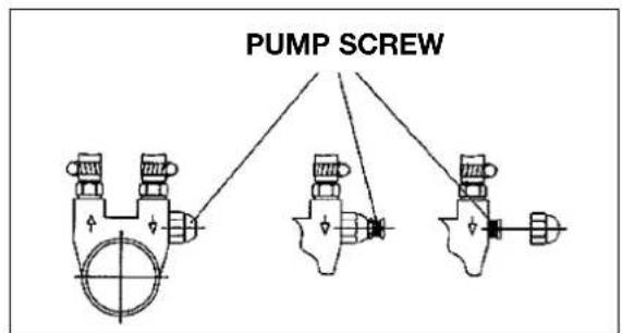
turning clockwise; it is decreased by turning counterclockwise. As shown in the following figure, there are three different cases for adjusting this screw, depending on the pump installed on the machine:
- adjust only the screw
- adjust the screw and lock it with the lock nut
- unscrew the cap nut and adjust the screw.
5.3 Adjustment of steam pressure in boiler
The steam pressure in the boiler is shown on the upper graduated scale of the pressure gauge B (figure 13). The lower graduated scale indicates the operating pressure of the pump. To change the pressure of the liquid-saturated steam mixture inside the boiler, you will need to vary the temperature as explained in the programming chapter.
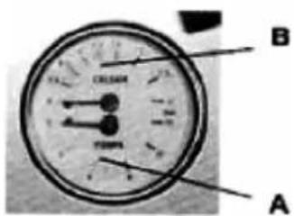
Figure 13
5.4 Adjustment of temperature of dispenser groups
In models TOP 85 (except for models TOP 85 DTC) the temperature can be adjusted for the serving of es- presso coffee without changing the internal pressure of the boiler. At the head of the serving group, there is a valve (flow rate variator) positioned at the top of the brewing unit adjusts the flow of hot water arriving from the exchangers; this valve can be accessed from the top by removing the upper protection from the units, removing the 2 screws (figures 14). Four numbers are printed above each unit (2-3-4-5) in correspondence of each brewing unit (figure 15). The valve is normally set to number 3 (this is the default setting provided by LA SAN MARCO SPA). If you want to change the serving temperature, you will need to use the valve (flow variator) of the group. To increase the temperature, turn the valve towards the higher numbers. Contrarily, to decrease, turn the knob towards lower numbers.
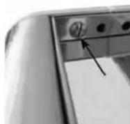
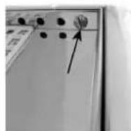
Figure 14
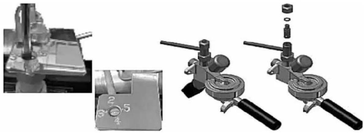
Figure 15
5.5 Additional notes for models TOP 85 DTC (Dual Temperature Control)
The cooling system of the models TOP 85 DTC has the purpose of ensuring thermal stability of the water used for serving espresso coffee. This system uses a special serving group in which the cold water from the mains passes through a small tube located in a compensation chamber. The hot water from the heat exchanger of the boiler passes through the serving group and comes into contact with the cooling tube. As a result it loses heat.
6. Operating instructions

During the flow of espresso coffee, tea or steam, these substances can cause burns due to accidental skin contact.
Each brewing unit has a pushbutton panel with five buttons (four for the programmed doses and one for manual doses. While brewing, a luminous bar appears on the display that simulates the progress of the coffee dose. The duration of brewing in seconds is always shown on the display.
Note:
Make sure that serving into the cup has taken place correctly. If serving has not occurred correctly, see the chapter "PROBLEMS AND SOLUTIONS".
6.1 Serving of espresso coffee
1) Remove the filter-holding cup from the serving unit and fill it with a dose of ground coffee (filter cup with one spout) or with two doses of ground coffee (filter cup with two spouts). Press the ground coffee using the relative coffee presser and then insert the filter cup into the serving unit.
2) Place one or two cups under the serving spouts.
Brewing is always enabled and does not depend on the boiler temperature or the water level in the boiler, except in the case of the maximum boiler level (brewing is not possible in this case).
After applying the filter holder cup to the unit, press one of the five buttons for the unit to be used:
| Short programmed single dose |
| Long programmed single dose |
| Short programmed double dose |
| Long programmed double dose |
| Manual continuous dose |
Programmed dose brewing
The LED relative to the button of the preselected dose will flash while the coffee is brewing. The other buttons will remain lit with a fixed light. When brewing is complete, the light on the selected button will again be fixed. Press the selected button again if you want to stop the programmed brewing before the dose has been reached.
Brewing coffee in START-STOP mode
By pressing one of the continuous dose buttons, the LED for the selected button will flash while the coffee is brewing. The other buttons will remain on with a fixed light during the brewing cycle.
To stop the continuous brewing, STOP the dose by pressing the selected button again.
Brewing in continuous mode is stopped automatically (if not stopped manually) when the maximum product quantity of approx. 0.5 litres is reached.
Note:
The dosing makes it possible to brew coffee in all units at the same time.
Each group has a push-button dispensing with five buttons (four for the programmed doses and one for manual doses. On display also is a bar graph that simulates (filling) the amount of coffee when making coffee.
6.2 Drawing steam
A jet of steam, which can be used to foam milk or to heat other liquids, comes out of the steam drawing spout as follows: by raising or lowering the lever you attain the maximum flow (the lever stops in the maximum position. To stop the flow of steam, place the lever back in its original position).

The steamer must be used with care: the contact of the skin with the steam spout or with the jet of steam itself can cause serious burns. Grip the anti-burn sheath to change the position of the steam drawing spout. Never aim the jet of steam at persons or at objects which do not have to do with the use as described in this manual.
Note:
Before using the spout for drawing steam, drain out into the tub any condensation which may have formed in it. After using the spout, clean it properly with a moist cloth, and if necessary discharge any residue remaining inside it into the tray.
6.3 Hot water outlet
Use the hot water keypad 8 to collect hot water from the boiler for tea, chamomile, etc.
The keypad has three keys (two for the programmed doses and one for manual doses). While the water comes out, the display shows a light bar that simulates (by filling up) the hot water doses; the display also shows the seconds required for the operation.
Place a cup under the dispensing spout and select one of the keys indicated below.
| Short programmed dose |
| Long programmed dose |
| Continuous manual dose |
PROGRAMMED DOSE
By pressing one of the two programmed dose keys, the LED linked to the key of the selected dose flashes while the hot water is dispensed; the other keys remain lit. Once the operation has been completed, the selected key stops flashing.
Press the selected key again to interrupt the water flow before reaching the programmed dose.
DISPENSING IN START-STOP MODE
By pressing the continuous dose key, the LED flashes while the hot water is dispensed; the other keys remain lit for the entire duration of the operation.
To interrupt the water flow in continuous mode, STOP the dose by pressing the same selected key.
The water flow in continuous mode is stopped automatically (if it is not stopped) after 40 seconds.
6.4 Automatic washing system
The automatic washing system allows the cleaning of coffee brewing groups.
Insert the filter holding cup with blind filter in the brewing group.
To start the washing cycle press the continuous dose key together with the short coffee single dose key for a few seconds. The two keys are blinking and the cycle starts automatically.
At the end of the washing cycle the brewing group returns to its normal operating conditions.
Repeat the washing cycle for all the other groups in the same way.
6.5 Cup heater (optional)
The cup heater is used to increase heating of the upper cup support surface (by means of an electrical heating element). Use the appropriate switch to activate or de-activate the cup heater. The cup heater heating element is equipped with a working thermostat that controls the temperature of the cup support surface.
7. Using the display keyboard
MENU: to access programming/reading/change
ESC: to exit the programming/reading/change pages
NEXT: to go from one screen to the next
OK: to confirm the selection or confirm the change
//:selectionbuttons
- / + : buttons for increasing or decreasing the programmable value or activating or deactivating a function
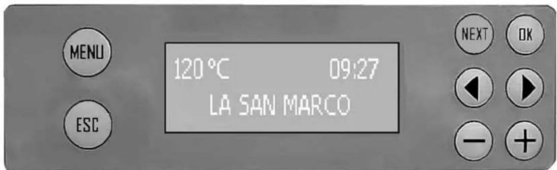
| Screen 1 Initial screen. | Visible for about 10 seconds after machine is turned on. |
| Screen 2 120°C —— HH:MM LA SAN MARCO | Machine ready screen. This screen is normally visible when not brewing or when the pro- gramming menu has not been accessed. The display shows the temperature of the boiler, the time and based on what was selected in screen 19, a text with a name or a day and date. If the boiler heating element is heating, the image will appear. This screen can always be used for any dosing operation. |
| Screen 3 (user) G1 000 G2 000 | Machine brewing screen. The icon of the selected cup appears on the screen when pressing a dose button. During the brewing operation, pressing the button displays the unit information, with the progress bar and the brewing duration in seconds. During the brewing operation, pressing the butt displays only the cups. At the end of brewing, the last selected view remains displayed. At the end of brewing, if a brewing time has been detected that is too long or too short in comparison to what is programmed, screen 42 signalling check grinding/dose will appear. After a few seconds, the machine ready screen 2 will appear. |
8. Programming
8.1 Menu access
| Screen 4 Programming/c | counter/service menu access screen. |
| This is accessed by pressing the MENU button for at least 5 seconds. When the screen appears, the counter reader icon (central) will flash The buttons ↓; ▷ are used to select one of the three icons: user level programming. counter reading. technical level programming. To access user programming press the OK button. To access counter reading press the OK button. To access technical programming press the combination of the required keys (OK and +) for at least 5 seconds. If no ICON is selected within 30 seconds, the machine ready screen will appear automatically (screen 2). Pressing ESC returns to the machine ready screen (screen 2). |
8.2 Programming the doses
| SELECT DOSE TO PROGRAM | When this screen is displayed, the doses can be programmed for each single button for every single unit. Selecting one of the buttons accesses screen 6 and the selected button will start to flash. Press NEXT to go to screen 7. If no button is selected within 30 seconds, the machine ready screen will appear automatically (screen 2). Pressing ESC returns to the machine ready screen (screen 2). |
| Screen 6 | Selected button dose programming screen. The selected button will start to flash and the screen indicating the unit associated with the button will appear together with the cup with the indication of the coffee dose (single or double, short or long) and the dose set in ml (cc). This screen can also be used to adjust the dose, increasing or decreasing it simply with the buttons + and -. The dose can also be programmed by self-learning. In this case, press the selected flashing button, start normal brewing and when the button is pressed again, the dose in ml is shown on the display. The programmed value will continue to flash, press Ok to store the value and return to screen 5. After the change, the programmed button will turn off to help understand which doses have been changed during that access to the programming page. If no button is selected within 30 seconds, the dose selection screen will appear automatically (screen 5) without saving the change. Pressing ESC returns to the dose selection screen (screen 5) without saving the change. |
| Screen 7 | Screen for copying dose programming to other units. The ↓; ▷ buttons can be used to select one of the machine units G2, (G3 and G4 if present). Pressing Ok copies the programmed doses for unit 1 also to the selected unit. They can also be copied by pressing the continuous dose button relative to the unit to which the doses should be copied from unit 1. Pressing the Ok button and the continuous dose button for the unit to be programmed will copy the programmed doses and return to screen 4. Obviously the individual doses of the various units can be programmed later using the procedure used for the previous screens. Press NEXT to go to the next screen. If the Ok button is not selected within 30 seconds, the machine ready screen will appear automatically (screen 2). Pressing ESC returns to the machine ready screen (screen 2). |
8.3 Programming the boiler temperature
| Screen 8 Boiler temperature BOILER TEMP. 120°C | ure programming screen. This screen is used to adjust the boiler temperature and to set the reading to °C or °F. Pressing < sets the temperature in °C. Pressing > sets the temperature in °F. Pressing + increases the value of the step 1 temperature (°C or °F). Pressing - decreases the value of the step 1 temperature (°C or °F). The value can be set from a minimum of 80°C (176°F) to a maximum of 128°C (262°F). Default setting: 120°C (248°F) Press OK to confirm the change. Press NEXT to go to the next screen. If the NEXT button is not selected within 30 seconds, the machine ready screen will appear automatically (screen 2). Pressing ESC returns to the machine ready screen (screen 2). |
8.4 Date/time programming
| Screen 9 Date/time programming screen. | ||
| TIME - DATE 15:04 FRI 05.04.13 | This screen is used to set the date and time. When the screen is accessed, the time will flash. Pressing the ↓/▶ buttons will move the selection and once the value to be adjusted has been selected (in order from left to right, hour, minutes, day of the week, day, month and year) pressing + / - changes the value. Press OK to confirm the change. Press NEXT to go to the next screen. If the NEXT button is not selected within 30 seconds, the machine ready screen will appear automatically (screen 2). Pressing ESC returns to the machine ready screen (screen 2). | |
8.5 Programming automatic on/off
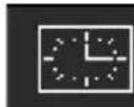
| Screen 10a AUTO ON 15:00 Screen 10b AUTO ON - - - | AUTO ON programming screen. This screen is used to activate/deactivate and set the automatic ON for the machine every day. Pressing the ↓/▶ buttons moves the selection. If the CLOCK icon is selected, + / - are used to activate or deactivate the AUTO ON function, if deactivated (CLOCK ICON CROSSED OUT) the following appears instead of the hour and minutes - - - , if activated, the ↓/▶ buttons can be used to go to the hour and minutes to set the required ON time using the + / - buttons. NOTE: if switching ON has been disabled, also OFF and day off remain automatically disabled. Press OK to confirm the change. Press NEXT to go to the next screen. If the NEXT button is not selected within 30 seconds, the machine ready screen will appear automatically (screen 2). Pressing ESC returns to the machine ready screen (screen 2). |
Screen 11a
AUTO OFF
19:00
Screen 11b

AUTO OFF
AUTO OFF programming screen.
This screen is used to activate/deactivate and set the automatic OFF for the machine every day.
Pressing the / buttons moves the selection.
If the CLOCK icon is selected, + / - are used to activate or deactivate the AUTO ON function, if deactivated (CLOCK ICON CROSSED OUT) the following appears instead of the hour and minutes --. --, if activated, the / buttons can be used to go to the hour and minutes to set the required OFF time using the + / - buttons.
NOTE: if switching ON has been disabled, also OFF and day off remain automatically disabled.
Press OK to confirm the change.
Press NEXT to go to the next screen.
If the NEXT button is not selected within 30 seconds, the machine ready screen will appear automatically (screen 2).
Pressing ESC returns to the machine ready screen (screen 2).
8.6 Programming day off
Screen 12 Day off programming screen.
DAY OFF
SUN
This screen is used to activate/deactivate and set the day OFF of the week on which the machine will remain off.
Pressing the + / - buttons sets the day OFF according to the sequence MON, TUE, WED, THU, FRI, SAT, SUN, OFF.
If OFF is set, the function is not active.
Press OK to confirm the change.
Press NEXT to go to the next screen.
NOTE: when the machine is off on the day OFF, it can always be reactivated by pressing the OK button for 5 seconds. Press the OK button again to turn it off again.
If the NEXT button is not selected within 30 seconds, the machine ready screen will appear automatically (screen 2).
Pressing ESC returns to the machine ready screen (screen 2).
8.7 LED RGB cup tray lighting programming
Screen 13 a

LED OFF
Screen 13 b

LED WHITE
LED RGB cup tray lighting programming screen.
This screen is used to activate/deactivate and set the colour of the LED RGB cup tray lighting.
If the BULB icon is selected, + / - are used to activate or deactivate the cup tray lighting function, if deactivated (BULB ICON CROSSED OUT) OFF will appear instead of the colour, if activated the / buttons can be used to move to the colour for setting the desired LED colour (white, blue, red or green) using the + / - buttons.
Default setting:WHITE
Press OK to confirm the change.
Press NEXT to go to the next screen (no. 5) and resume the sequence of the user level programming screens.
If the NEXT button is not selected within 30 seconds, the machine ready screen will appear automatically (screen 2).
Pressing ESC returns to the machine ready screen (screen 2).
9. Counter reading
9.1 Read total litres count
Screen 14 a
LITRES TOTAL
100000
Screen 14 b
LITRES PARTIAL
100000
Screen 14 c
SOFTENER CHANGE
WITHIN 500 LITRES
Total litre count reading screen.
The first count screen indicates the total quantity of litres loaded from the machine. These screens will not be displayed if the water counter was not enabled on screen 43.
Pressing the / buttons moves between the display of the three screens.
If screen 14b is displayed, pressing the Ok button for at least 5 seconds will reset the partial counter.
Press NEXT to go to the next screen.
If no button is selected within 30 seconds, the machine ready screen will appear automatically (screen 2).
Pressing ESC returns to the machine ready screen (screen 2).
Total coffee count reading screen.
The second count screen indicates the total number of coffees made by the machine.
Pressing the / buttons moves between the display of the three screens, indicating the number of total and partial coffees for the machine and for each individual unit
If one of the partial coffee screens for the individual units is displayed, pressing the Ok button for 5 seconds will reset the partial counter for each individual unit.
Press NEXT to go to the next screen.
If no button is selected within 30 seconds, the machine ready screen will appear automatically (screen 2).
Pressing ESC returns to the machine ready screen (screen 2).
9.3 Read partial and total single coffee dose count
Screen 16 a
COFFEE SINGLE DOSES
SELECT DOSE
Screen 16 b

PAR 100000
TOT 100000
Read partial and total single coffee dose count screen.
The third count screen displays the number of total and partial doses brewed for any dose relative to any unit.
The initial screen displays the partial and total number of the single short dose of the first unit.
The / buttons can be used to display the various doses in sequence, or it will be possible to directly view the status of any dose by pressing the relative button.
If one of the 16b screens is displayed, pressing the Ok button for at least 5 seconds will reset the partial counter.
Press NEXT to go to the next screen.
If no button is selected within 30 seconds, the machine ready screen will appear automatically (screen 2).
Pressing ESC returns to the machine ready screen (screen 2).
10. Technical level programming
10.1 Software information screen
Screen 17 Version information technical level programming screen.

The first screen relative to the technical level programming displays information about the program version.
By selecting the icon to the left with the / buttons, it is possible to select which machine is being used - 2G, 3G or 4G. Press OK to confirm.
Selecting the icon to the right with the / buttons and pressing the OK key accesses screen 44, which can be used to indicate if the infuser is not present for each unit.
Press NEXT to go to the next screen.
If no button is selected within 30 seconds, the machine ready screen will appear automatically (screen 2).
Pressing ESC returns to the machine ready screen (screen 2).
10.2 Infuser
Screen 44 Infuser technical level programming screen.

This technical level programming screen is used to inform the machine if the infuser has not been installed on one or more units.
Select the unit using the / buttons. The - button displays a flashing NO and the + button a flashing YES.
Pressing the OK button confirms the change and the value will again be fixed.
Default setting: YES
If no button is selected within 30 seconds, the machine ready screen will appear automatically (screen 17).
Pressing ESC returns to the machine ready screen (screen 17).
10.3 Language selection screen
Screen 18 Language technical level programming screen.

This technical level programming screen is used to select the set language.
Select the language with the / buttons and press OK to confirm. The set language will be underlined and the one being changed will flash.
Default setting:ITALIAN
Press NEXT to go to the next screen.
If no button is selected within 30 seconds, the machine ready screen will appear automatically (screen 2).
Pressing ESC returns to the machine ready screen (screen 2).
10.4 Display message screen
Screen 19 a

Display message technical level programming screen.
This technical level programming screen displays the selection of the user name or the option of displaying the date on machine ready screen 2, IDLE-ON status.
Use the / buttons to select NAME or DATE, pressing the OK button on DATE will display the set date on screen 2, for example FRI 12.04.2013. If NAME is selected, screen 19b appears that can be used to change the name of the user to be displayed on screen 2.
Move using the / buttons and change the symbol or letter with the + / - buttons. Default setting: LA SAN MARCO Press NEXT to go to the next screen. If no button is selected within 30 seconds, the machine ready screen will appear automatically (screen 2). Pressing ESC returns to the machine ready screen (screen 2).
Screen 19 b

10.5 Service number setting screen
| Screen 20 Service number | technical level programming screen. |
| SERVICE PHONE | This technical level programming screen is used to set the ser-vice number. |
| XXXXXXXXX | Move using the ↓ / ▶ buttons and change the number with the + / - buttons. |
| Default setting:XXXXXXXXXX | |
| Press Ok to confirm the change. | |
| Press NEXT to go to the next screen. | |
| If no button is selected within 30 seconds, the machine ready screen will appear automatically (screen 2). | |
| Pressing ESC returns to the machine ready screen (screen 2). |
10.6 Dose change activation screen
| Screen 21 Dose change activation technical level programming screen. | |
| DOSES SETTING ENABLE | This technical level programming screen is used to activate or deactivate the possibility to adjust doses. Use the + / - buttons to activate or deactivate the possibility of pro-gramming the doses. Press Ok to confirm the change. Default setting: ACTIVE Press NEXT to go to the next screen. If no button is selected within 30 seconds, the machine ready screen will appear automatically (screen 2). Pressing ESC returns to the machine ready screen (screen 2). |
10.7 Continuous dose activation screen
| Screen 22 Continuous dose activation technical level programming screen. CONTINUOS DOSE ENABLE | This technical level programming screen is used to activate or deac- tivate the possibility of dispensing continuous doses with the units. Use the + / - buttons to activate or deactivate the possibility of dis- pensing continuous doses. Press Ok to confirm the change. Default setting: ACTIVE. Press NEXT to go to the next screen. If no button is selected within 30 seconds, the machine ready screen will appear automatically (screen 2). Pressing ESC returns to the machine ready screen (screen 2). |
10.8 LED RGB cup tray lighting activation screen
| Screen 23 a LED DISABLE Screen 23 b LED ENABLE | LED RGB cup tray lighting activation technical level program- ming screen. This technical level programming screen is used to activate or deac- tivate cup tray lighting. Use the + / - buttons to activate or deactivate cup tray lighting. Press Ok to confirm the change. Default setting: ACTIVE. Press NEXT to go to the next screen. If no button is selected within 30 seconds, the machine ready screen will appear automatically (screen 2). Pressing ESC returns to the machine ready screen (screen 2). |
10.9 Preinfusion activation screen
| Screen 24 a P PREBREWING ENABLE Screen 24 b P PREBREWING DISABLE | Preinfusion activation technical level programming screen. This technical level programming screen is used to activate or deac- tivate preinfusion. Use the + / - buttons to activate or deactivate preinfusion. Press OK to confirm the change. Default setting: NOT ACTIVE Press NEXT to go to the next screen if preinfusion is active, if preinfu-sion is set as not active screen 27 will not be displayed. If no button is selected within 30 seconds, the machine ready screen will appear automatically (screen 2). Pressing ESC returns to the machine ready screen. |
| Screen 25 PREBREWING SELECT GROUP | Set preinfusion technical level programming screen. When this screen is displayed, preinfusion can be programmed for all buttons for every single unit. All buttons are on, selecting one of the buttons (for example, single long dose button for unit 1) will display screen 26. Press NEXT to go to screen 27. If no button is selected within 30 seconds, the machine ready screen will appear automatically (screen 2). Pressing ESC returns to the machine ready screen (screen 2). |
10.10 Single dose preinfusion screen
| Screen 26 Single dose preinfusion programming screen. | |
| G1 P tON 3.0 tOFF 2.5 | After selecting the unit on the previous screen or on this screen, the unit will start to flash and a screen will appear indicating the unit and set values for tON and tOFF. This screen can be used to adjust the tON and tOFF value, within the permitted limits, by simply increasing or increasing it using the + and - buttons and in steps of 0.1 seconds, after selecting them with the ↓ / ↑ buttons. Press OK to save the value and return to screen 25, or press another button for another unit to display the preinfusion setting for that unit. Setting tON to a value of 0 seconds disables preinfusion for all but-tons for the selected unit. Press NEXT to go to the next screen. If no button is selected within 30 seconds, the preinfusion selection screen will appear automatically (screen 25) without saving the change. Pressing ESC returns to the dose selection screen (screen 24) with- out saving the change. |
| PUMP EVx t1 (on) t2 (off) programmed dose total time dispensing | |
10.11 Number of service intervention cycles screen
| Screen 27 SERVICE 100000 CYCLES | Service intervention cycle number technical level program- ming screen. This technical level programming screen is used to set the number of cycles after which the intervention of technical service is shown on the display. Change the number using the + / - buttons from a value of 0 to 100000 in steps of 1000. If the set value is 0, the signal is disabled Default setting: 0 (function disabled) Press NEXT to go to the next screen. If no button is selected within 30 seconds, the machine ready screen will appear automatically (screen 2). Pressing ESC returns to the machine ready screen (screen 2). |
10.12 Water softener filter change signal
| Screen 28 Water softener CHANGE WATER 10000 LITRES | filter change signal warning setting technical level programming screen. This technical level programming screen is used to set the number of litres after which the need to replace the water softener filter is shown on the display. This screen will not be displayed if the water counter was not enabled on screen 43. Change the number using the + / - buttons from a value of 0 to 15000 in steps of 100. If the set value is 0, the signal is disabled. Default setting: 0 (function disabled) Press NEXT to go to the next screen. If no button is selected within 30 seconds, the machine ready screen will appear automatically (screen 2). Pressing ESC returns to the machine ready screen (screen 2). |
10.13 Dose deviation screen
| Screen 40 Dose deviation | technical level programming screen. |
| DOSE DEVIATION 30% | The following screen shows the deviation parameter from the pro- grammed dose by means of self-learning. Change the number using the + / - buttons from a value of 10 to 70 in steps of 1. Default setting: 60% The signal can be disabled by pressing the + button until OFF appears. Press OK to confirm the change Press NEXT to go to the next screen. If no button is selected within 30 seconds, the machine ready screen will appear automatically (screen 2). Pressing ESC returns to the machine ready screen (screen 2). |
10.14 Lower counter alarm limit screen
| Screen 41 Lower counter FLOW METER LIMIT 0.5 ml/s | alarm limit programming screen. The following screen is used to program the lower limit parameter for the quantity in ml per seconds for all counters, under which the counter alarm is indicated. Change the number using the + / - buttons from a value of 0.1 to 1 in steps of 0.1. Default setting: 0.5 Press NEXT to go to the next screen (29). If no button is selected within 30 seconds, the machine ready screen will appear automatically (screen 2). Pressing ESC returns to the machine ready screen (screen 2). |
10.15 Water counter screen
| Screen 43 Water counter | technical level programming screen. |
| WATER FLOW METER NO | This technical level programming screen is used to inform the machine if the water volume counter has been installed at the machine inlet. The - button displays a flashing NO and the + button a flashing YES. Pressing the OK button confirms the change and the value will again be fixed. Default setting: NO If no button is selected within 30 seconds, the machine ready screen will appear automatically (screen 17). Pressing ESC returns to the machine ready screen (screen 17). |
10.16 Default setting reset screen
| Screen 29 Default setting | reset screen. This screen is used to delete all the set parameters and restore the default settings. Use the ↓ / ▲ buttons to switch between NO and YES If YES is selected, press OK for at least 5 seconds to confirm the reset, screen 30 will appear on the display. Press NEXT to go to the next screen (no. 17) and resume the sequence of the technical level programming screens. Pressing ESC returns to the machine ready screen (screen 2). |
| RESET TO FACTORY SETTINGSNO | |
| Screen 30 | Default setting reset completed screen. This screen indicates that the default settings have been reset. Pressing ESC returns to the machine ready screen (screen 2). |
| FACTORY RESETDONE |
11. Alarm signals
11.1 Faulty counter screen
| Screen 31 Counter faulty ALARM FLOW METER G1 | signalling screen. This screen signals that there is a malfunction of one of the machine's impulse counters. The group with the malfunction is indicated. |
11.2 Water softener filter replacement screen
| Screen 32 Water softener | filter replacement signalling screen. |
| CHANGE WATER SOFTENER FILTER | This screen indicates that the machine's water softener filter must be replaced and appears when the value set on screen 28 is reached or exceeded. |
| This screen will not be displayed if the water counter was not enabled on screen 43. | |
| The warning is shown for 5 seconds after each brewing operation, but does not block the possibility of brewing coffee. | |
| To reset the signal and make the relative counter restart from 0, press the + / - buttons at the same time for at least 2 seconds. | |
| Once the counter is reset, screen 33 is displayed. | |
| Screen 33 | Water softener filter replacement signal reset screen. |
| This screen signals that the water softener filter replacement alarm was reset. | |
| This screen will not be displayed if the water counter was not enabled on screen 43. | |
| Pressing ESC returns to the machine ready screen (screen 2). |
11.3 Technical service signalling screen
| Screen 34 Need for technical service check signalling screen. | |
| RECOMMENDED MAINTENANCE | This screen indicates that the machine should be checked by technical service and appears when the value set on screen 27 is reached or exceeded. The warning is shown for 5 seconds after each brewing operation, but does not block the possibility of brewing coffee. To reset the signal and make the relative counter restart from 0, press the / buttons at the same time for at least 2 seconds. Once the counter is reset, screen 35 is displayed. |
| Screen 35 SERVICE RESET | Need for technical service check signalling reset screen. This screen signals that the need for a technical service check alarm was reset. Pressing ESC returns to the machine ready screen (screen 2). |
11.4 Boiler water level alarm signalling screen
| Screen 36 Low boiler water level alarm signalling screen. WATER LEVEL LOW | This screen signals that the water in the boiler is too low. The signal disappears only after the level has been corrected. |
| Screen 37 WATER LEVEL TOO HIGH | Boiler water level too high alarm signalling screen. This screen signals that the water in the boiler is too high. The signal disappears only after the level has been corrected. |
11.5 Boiler temperature alarm signalling screen
| Screen 38 Boiler temperature | If the boiler temperature probe is short circuiting or if the temperature is higher than the threshold of 140°C for more than 5 consecutive seconds, the alarm goes off, making all the button LEDs flash and displaying screen 38. All main dosing functions are inhibited. The keyboards are disabled and all actuators are inhibited from operating. The alarm only disappears after the temperature returns within acceptable values. The warning disappears when the machine is turned OFF. |
| Screen 39 ALARM TEMP. PROBE | Boiler temperature probe alarm signalling screen. If the boiler temperature probe is disconnected or interrupted, within 5 seconds an alarm goes off, making all keyboard LEDs flash and displaying screen 39. All main dosing functions are inhibited. The keyboards are disabled and all actuators are inhibited from operating. The alarm only disappears after the probe is reconnected. The warning disappears when the machine is turned OFF. |
11.6 Check grinding/dose signalling screen
| Screen 42 Check grinding/dose signalling screen. | |
| CHECK G2 GRINDING/DOSE | At the end of every brewing operation, a ratio is calculated between the quantity brewed and the duration. If the result lies outside the range defined by the parameter on screen 40, the display will indicate CHECK GRINDING/DOSE, also indicating the unit with the error. The signal disappears after 5 seconds. |
Screen 45 Water counter check signalling screen.

This appears if the counter does not detect the impulse count while brewing or the load for self levelling at the end of brewing or auto levelling.
This screen will not be displayed if the water counter was not enabled on screen 43.
It is not a blocking alarm, but only a signal that appears at the end of brewing or auto levelling.
It disappears after 5 seconds.
11.7 Possible water leak signalling screen
Screen 46 Possible water leak signalling screen.
WARNING POSSIBLE LOSS OF WATER
This appears if the counter detects an impulse count for at least 5 seconds when brewing or loading for self-levelling is not in progress. This screen will not be displayed if the water counter was not enabled on screen 43.
The signal disappears after 10 seconds and reappears after one minute unless there the machine is brewing or auto levelling, in which case the signal appears only after completing brewing or auto levelling.
11.8 Volumetric counter alarm
On models TOP 85, all equipped with six-LED bar, if there is no detection of impulses of the volumetric counter for 5 seconds, the LED's that are already on will start flashing to indicate the anomaly. If the anomaly is detected before any of the LED's on the bar come on, only the LED of the short coffee key for the concerned group will flash.
If no impulses of the volumetric counter are detected for 45 consecutive seconds, the amount of coffee being served is automatically interrupted. GX COUNTER ALARM
Note:
Make sure that serving into the cup has taken place correctly. If serving has not occurred correctly, see the chapter "PROBLEMS AND SOLUTIONS".
11.9 Autolevel alarm
If the water level in the boiler is below normal and the pump is not able to restore that level after 200 seconds, the electronic control unit of the machine will stop automatic filling and signal the problem via simultaneous flashing of the double short coffee button of all groups plus the large tea key and the first of the three LED's of the electronic level control.
Note:
The following appears on the display: LOW BOILER WATER LEVEL. If the boiler is not properly filled with water, see the chapter on problems and solutions.
11.10 Maximum water level in boiler alarm
If the level of water in the boiler is over the safe level, the electronic control unit will stop automatic filling and signal the problem through simultaneous flashing of the serving buttons plus the three LED's of the electronic level control. LOW BOILER WATER LEVEL.
Note:
If the maximum boiler level alarm trips, see the chapter on problems and solutions
11.11 Alarm for temperature sensor
If the level of water in the boiler is above the safety level, the electronic control unit will stop automatic loading and signal the fault by making the brewing buttons flash at the same time together with the three electronic level leds and the following appears on the display: BOILER WATER LEVEL TOO HIGH.
If the temperature probe is short circuiting, the following appears on the display: BOILER TEMPERATURE
12. Routine maintenance

-
No panel or fixed guard of the frame may be removed from the machine to carry out the routine maintenance.
-
Do not use harsh or harmful detergents such as alcohol, petrol or solvents to clean the coffee machine; use water and neutral detergents.
Note:
The daily cleaning operations must be carried out in order to maintain the efficiency of the machine and to guarantee the safety of the user and of the persons around it.
12.1 Cleaning the serving units and the filter holder
1) Release the filter holder from the group dispensing, remove the coffee grounds and filter change this with the blind filter ( without holes ) supplied with the machine.
2) Before cleaning the unit mounted on the protective glass as in the photo.
Note:
The filter is inserted inside the cup pressure , to remove enough force on the sides and then pull it out . Do notremove the snap ring inside the filter holder
3) Clean the brush supplied with the group's headquarters where you insert the filter holder.
4) Place the cup in the group and press the button completely without docking continuous delivery .
5 ) Allow to drain the water to overflow from the filter holder ( in this way you clean the dispensing group ) .

The continuous flow of water from the unit can cause burns due to accidental skin contacts.
6) Stop the water supply and lock the bowl in the group.
7) Start the continuous delivery and then stop after a couple of seconds and repeat this a few times (so that you clean the drain channel and the solenoid valve of the dispensing unit).
8) Clean the filter drilled and put it back in the cup. Supply water for a couple of seconds to clean the filter, the cup spouts.
9) Repeat the same operation on all groups dispensing.
Note:
Special commercially available detergents can be used to effectively clean the serving units.
12.2 Cleaning the tray and the cup support grill
The lower cup support grill 5 must be kept clean at all times; during the normal use of the machine, it is sufficient to clean it with a sponge or a moist cloth. At the end of the working day, clean the tray and the grill also in the internal areas using warm water and neutral detergent.
12.3 Cleaning the steam spout
Clean the steam spout with a sponge or a moist cloth at the end of the working day to remove all traces of milk or other substances that inevitably form during the normal operation of the machine. Open the steam tap, placing the spout in the tub, to remove any residues which may have accumulated in the spout.
12.4 Substitution of boiler water
To change the water inside the boiler, proceed as follows:
1) Cut off the power supply to the machine by turning the main switch 1 to position 0 (zero).
2) Remove the tub and the cup support grille and open the boiler drain tap.
3) Open a steam drawing valve to facilitate the draining of the water until the end of the operation.
4) When water no longer comes out of the boiler, close the boiler drain and the steam drawing tap.
5) Charge the machine with water following the instructions of paragraph "Charging the water in the boiler".
6) To improve product quality, it is recommended to replace the water in the boiler and to change the water contained in the water circulation pipes when starting the machine every day.
13. Idle periods
If the machine is to remain idle for long periods (weekly closing days, holidays, etc.), take the following precautions:
1) Turn the main switch to 0 (zero) and as necessary disconnect the power cord or the main switch of the electrical mains.
2) Close the cut-off valve of the water mains.
3) If you think the temperature might drop below 5ircC , completely drain the water system of the machine.
4) Wash the components of the machine as described in the paragraph on routine maintenance.
5) Cover the machine if necessary.
14. Safety devices
14.1 Manual reset safety thermostat
The safety thermostat is located next to the control unit and can be accessed by removing the left side panel from the machine. The thermostat probe, placed inside the electric heating elements, cuts the electric power supply any time there is an abnormal increase in temperature. The heating elements will no longer hear the water in the boiler and it will not be possible to use the machine correctly. Contact a technician from the LA SAN MARCO SPA technical service centre.

The safety thermostat will have to be reset by the specialized technician LA SAN MARCO SPA, who must first remove the cause of the malfunction.
14.2 Safety valve
The safety valve is installed on the upper part of the boiler, in the part corresponding to the area occupied by the steam. The valve is activated if there is a considerable pressure increase inside the boiler. The valve rapidly lowers the pressure by expelling the steam in the atmosphere (the valve trips in at 2 ÷ 2.5 bar). If the safety valve trips in, the steam is held and dissipated inside the machine frame, so as to avoid hazards for the persons around the machine.

In case of activation of the safety valve, switch off the machine and immediately contact the specialized technician. If the safety valve is set off, switch the machine off and immediately contact the authorized La San Marco technician.
15. Information for users in the european community

Pursuant to European Directive 2012/19/EU on electrical waste (WEEE), users in the European community are advised of the following.
- The symbol with the crossed-out dustbin on the appliance or its packaging indicates that at the end of the product's life cycle, it must be collected separately from other waste.
- Suitable separate collection of the equipment for subsequent recycling, treatment and disposal contributes to preventing possible negative consequences for the environment and health, and favours the recycling of materials that the unit is made of.
- In accordance with European Directive 2012/19/EU, abusive disposal of the product by the user will result in application of penalties as set forth by local law.
16. General warranty conditions
- The warranty lasts 12 months starting from the date of the invoice.
- For warranty the free substitution of the components of the machine are intended, which have to be recognized by La San Marco to have manufacturing defects. The warranty applies only to the original components, and it falls in case of the use of unoriginal components or of an the machine itself.
- The warranty doesn't apply to the substitutions or to the reparations that result by a normal functioning usury of the device, from deterioration or accidents provoked by a negligence or carelessness in the use.
- The electric parts, and all the parts that result to be defective because of damage linked to transport, wrong installation, bad maintenance operated by non authorized staff, by the missing or improper use of the water softener system or the water entrance filler, by the improper use of the machine or a different use from the one the machine was built for or, lastly, by circumstances that can't be attributed to manufacturing defects.
- The labour and the technical interventions linked to the installation of the machine, the parts subjected to normal usury and all the consuming material are excluded from the warranty service.
- The components are covered by the warranty only if they are rendered complete in all their parts, they must not result to be altered and the manufacturing defects mustn't be cancelled, removed or made illegible.
- The substitution of the machine and the extension of the warranty is excluded after a malfunction occurred. The reparation, change or substitution of the pieces during the warranty period can't have the effect to extend the warranty period. All the actions and claims are excluded from the warranty's coverage, especially those that tend to the reparation of the direct or indirect damage caused by people or other objects that are different from the delivered products, and also the refund of the eventual missed profits.
- La San Marco S.p.A declines every responsibility for eventual damage that could derive, directly or indirectly to people, animals of things as a consequence of the missing observance of all the prescriptions indicated in the user manual that accompanies every product and concerning, especially, the warnings about the installation, use and maintenance of the machine.
- The warranty concerns the free substitution of the defective pieces with the relative free dispatch of the pieces of substitution to the buyer; the warranty doesn't cover the labour. The dispatch of the defective pieces to the supplier is charged to the buyer.
- Every returned component of which the substitution covered by the warranty is asked for, has to be agreed with the client and approved by the commercial office of La San Marco to be accepted.
- La San Marco S.p.A declines every responsibility for eventual damage caused, directly or indirectly, from the improper use of the machine, from the wrong installation or bad maintenance, excluding what explicitly previewed by the law.
- La San Marco S.p.A doesn't answer to warranty conditions, beyond those listed, conceded by the importers/dealers to their clients. Also the obligations of labour are excluded from the warranty of La San Marco, travel and added costs relative to the reparation or substitution of the defective components of the machine.
- If, after a examination of La San Marco the returned component didn't result defective, the client will be charged with the management costs, technical control and possible tests. Also the charges for the shipping and the restitution of the material will be charged.
17. Declaration of conformity (€
The manufacturer:
La San Marco S.p.A.

declares under its own responsibility that the ESPRESSO COFFEE MACHINE (as identified by the data on the tag located on the machine) is complaint with the following European directives: 2006/42/EC; 2014/35/EU; 20014/30/EU, Regulation (EC) no. 1935/2004, 2012/19/EU, 2011/65/EU.
For verification of compliance with said directives, the following harmonized standards have been applied: EN ISO 12100, EN 60335-1, EN 60335-2-75.
AUTHORISED PERSON A
COMPILE THE TECHNICAL FILE
Ing. Roberto Nocera
Gradisca d'Isonzo, April 2018
Mr Roberto Nocera
C.E.O.

18. Problem solving
| PROBLEM CAUSE | SOLUTION | ||
| 1. | ·The boiler is full of water and the water flows out of the safety valve. | ·One of the outflow lines from the boiler or from a circuit of the unit has a leak. | ·Check the autolevel circuit, the manual charging button, and the boiler heat exchangers. ·Replace worn or damaged parts to eliminate the leak. |
| 2. | ·The safety valve trips in and vents the steam. | ·Malfunction of electrical system (the electrical heating element is always connected). ·Pressure increase in the boiler (the safety valve trips in at 2-2.5 bar). | ·Check the wiring that feeds the heating element and the pressure switch. |
| 3. | ·The machine was started properly but the water in the boiler does not warm up. | ·The electric heating element is defective or is not connected. ·Main switch turned to position 1. | ·Check if the heating element is connected to the power supply. ·Check if the heating element safety thermostat has tripped in and check its proper operation. ·The main switch must be turned to position 2 |
| 4. | ·There is no water flowing from a serving unit. | ·Coffee ground too fine or excessive quantity for type of filter used. ·Clogged water circuit. ·Defective solenoid. | ·Adjust the grinding coarseness and/or the quantity of ground coffee. ·Check that the injector, the upper circulation pipe, the valve (flow variator) of the group, the water dispenser and the solenoid valve of the group are not clogged. ·In the machines with electronic metering, check the displacement meter and its valves. ·Check the solenoid of the unit, its wiring and the fuse in the electronic control unit. |
| 5. | ·The programmed servings of espresso coffee are not constant or vary on the different units. | ·Abnormal operation of the electronic control unit or of the displacement counters. ·Leak from serving unit solenoid valve. ·Water dispensers clogged. | ·Program the serving quantities separately on each serving unit. If the problem persists, replace the displacement meter of the serving unit affected. ·Replace the solenoid valve of the serving group. ·Check the water dispenser. |
| 6. | ·It is not possible to program the serving quantities on unit 1 and to copy them on the other units. | ·Abnormal operation or defective displacement meter of unit 1. | ·Check the control unit-displacement meters electrical wiring. ·Replace the displacement meter. |
| 7. | ·Displacement meters alarm. | ·Displacement meters jammed or defective. ·Defective wiring. | ·Replace the volumetric counter. ·Check the wiring and its connections, the control unit and the fuses. |
| 8. | ·Autolevel alarm. ·Water | circuit of automatic level without water. ·Main water supply valve closed. ·Faulty autolevel solenoid. | ·Check the hydraulic circuit of the autolevel. ·Check if the on-off valve on the water supply is open. ·Replace the autolevel solenoid. |
| PROBLEM CAUSE SOLUTION | |||
| 9. | • Overfill alarm • Malfunction | on automatic level circuit. • Leak in button for manual water filling. • Leak in heat exchangers. | • Check the hydraulic circuit of the autolevel. |
| 10. | • The machine is switched on (the main switch is in position 1 or 2 and the signal light is lit) but the electronic control is out of order. | • The electric wiring of the electronic control unit is defective. • The electronic control unit is defective. | • Check the electrical wiring, the electronic control unit and its components. • Replace the electronic control unit. |
| 11. | • The machine feeds water from one serving unit although the serving has not been selected. | • Solenoid and/or pump fed continuously. | • Control unit relay powered continuously. • Replace the electronic control unit. |
| 12. | • One unit serves water continuously. | • Electric circuit of unit improperly connected. | • Check the connection and correct it (see wiring diagram). |
| 13. | • The steamer discharges only small quantities of steam or water droplets. | • Tap needs adjustment. • Worn gasket on tap. | • Adjust tap. • Replace the gasket. |
| 14. | • Some drops come out of the dispensing spout. | • Leak in solenoid valve. • Check | • the solenoid valve and replace it if necessary. |
| 15. | • The unit emits a whistle after serving the coffee. | • Faulty operation of expansion valve. • High pump pressure. | • Check the expansion valve and if necessary replace it. Calibrate the valve at 12 bar. • Check the pump operating pressure. Calibrate the pump at 9 bar. |
| 16. | • The filter cup comes off the serving unit. | • Worn gasket under the filter cup. | • Replace gasket. • Clean the serving unit and the filter cup. |
| 17. | • When coffee is being served, some of it drips out of the edge of the filter cup. | • Gasket under holder is worn. | • Replace the gasket. • Clean the serving unit and the filter cup. |
| 18. | • Water leaking from the drain of the serving unit solenoid. | • Malfunctioning unit solenoid. • Water leaking from unit cooling system. | • Check the unit solenoid. Check the plunger on the solenoid and clean the solenoid. • Replace the automatic level solenoid valve. • Check the small cooling tube and the related seals of the serving group (TOP 85 DTC). |
| 19. | • Light cream (the coffee flows out of the spout rapidly). | • Coarse grinding. • Low pressing pressure. • Small quantity of ground coffee. • Water temperature below 90°C • Pump pressure above 9 bar. • Sprinkler filter on unit clogged. • Filter holes widened (filter cup). | • Finer grinding. • Increase the pressure. • Increase the quantity of ground coffee. • Adjust valve (flow variator) of the group to a higher number or increase boiler pressure. • Decrease the pump pressure. • Check and clean with blind filter or replace. • Check and replace filter. |
| PROBIEM CAUSE | SOIUTION | ||
| 20. | · Dark cream (the coffee drips out of the spout). | · Fine grinding. · High pressing pressure. · Large quantity of ground coffee. · Excessive temperature. · Pump pressure below 9 bar. · Sprinkler filter on unit clogged. · Filter holes clogged (filter cup). | · Coarser grinding. · Reduce the pressure. · Decrease the quantity of ground coffee. · Adjust valve (flow variator) of the group to a lower number or decrease boiler pressure. · Increase the pump pressure. · Check and clean the solid filter or replace. · Check and replace filter. |
| 21. | · Presence of grounds in coffee cup. | · Coffee ground too fine. · Worn grinders in grinder-dispenser unit. · Pump pressure above 9 bar. · Sprinkler filter on unit clogged. · Filter holes widened (filter cup). | · Coarser grinding. · Replace the grinders. · Decrease the pump pressure. · Check and clean with blind filter or replace. · Check and replace filter. |
| 22. | · Coffee with too little cream in cup (spurts out of spout). | · Sprinkler filter on unit clogged. | · Check and clean with blind filter or replace. |
| 23 | · The cream in the cup is too thin (it disappears after a few seconds). | · Coffee extraction takes a long time due to clogged filter. · Coffee extraction too fast due to clogged sprinkler filter. · Water temperature too high. | · Clean or replace the filter. · Clean or replace the sprinkler filter. · Lower the temperature in the boiler. · Adjust valve (flow variator) of serving group. |
| 24. | · Presence of depressions in the coffee grounds (looking inside the filter cup). | · Sprinkler filter partly clogged. | · Clean or replace the sprinkler filter. |
Note:
If it is not possible to solve the problem as described above, or if other malfunctions develop, contact the authorized La San Marco service centre.
EMPPIOI ET ENTRETIEN SÉRIE TOP 85
2.2 Water system diagram key:
The machine packing contains the equipment kit, which includes the following items:
POMPE INTERNE (EN OPTION)
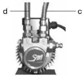
Figure 5 Figure 6 Figure 7
3.5 Evacuation
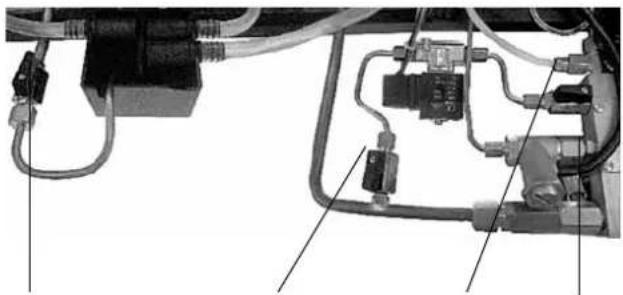
Figure 8 Figure 9 Figure 10
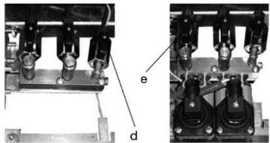
DOSE CONTINUE ACTIVER
1.4 Technical characteristics
| TOP 85 | AUSGAEBRUPPEN: KAFFEE AUSGAEBRUPPEN: KAFFEE DTC (OPTIONAL) | AUSGAEBRUPPEN: KAFFEE AUSGAEBRUPPEN: KAFFEE DTC (OPTIONAL) | DAMPFLANZEN | HEISSWASSERLANZEN | FASSUNG/SVERMÖGEN DES KESSEL (L) | GEWICH (KG) | BREITE (CM) | HOHE (CM) | TIEFE (CM) | INSTALLIERTE LEISTUNG (W) | |||||
| KESSELHEIZUNG | INTRINE MOTOR- PUMPE | EXTERNE MOTOR- PUMPE | TASSENWARMER (OPTIONAL) | ||||||||||||
| EINPHASIG | DREIPHASIG | ||||||||||||||
| TOP 85 SPRINT | 2 - 1 1 5 | 56 63 | 47 54,5 | 3000 | 4500 | 275 - - | |||||||||
| TOP 85 SPRINT 10L | 2 - 1 1 10 | 56 63 | 47 54,5 | 2800 | 4200 | 275 - - | |||||||||
| TOP 85 2 | 2 2 2 1 12 | 60 72 | 47 54,5 | 3500/4500 | Opt. | 300 100 | |||||||||
| TOP 85 3 | 3 3 2 1 19 | 74 96 | 47 54,5 | 5500/7000 | Opt. | 300 125 | |||||||||
| TOP 85 4 | 4 | 4 | 2 | 1 | 25 | 90 | 120 | 47 | 54,5 | 7000 | 7000/9000 | Opt. | 300 | 150 | |
| OPTIONAL: WASSERENTHÄRTER; MANUELLOLL MILCHAUFSCHAUMER; AUTOMATISCHE DAMPLANZE; TASSENABGRENER (Für MODELL 2,3,4 GRuppen); EXTERNE MOTOR-PUMPE 300 W (MODELL SPRINT); INTERNE MOTOR-PUMPE 275 W (Für MODELL 2,3,4 GRuppen); ELEKTRISCHER TASSENWARMER (2/3/4 GRuppen); BELEUCHTUNG DER ARBEITSFLÄCHE MIT LED-TECHNIK. | |||||||||||||||
Gradisca d'Isonzo, April 2018
Ing. Roberto Nocera
C.E.O.
Company with certified quality, environmental, health and safety management system according to UNI EN ISO 9001
UNI EN ISO 14001
BS OHSAS 18001
La San Marco spa
Espresso coffee machines since 1920

12x - 1 = 12x( 1 - x)
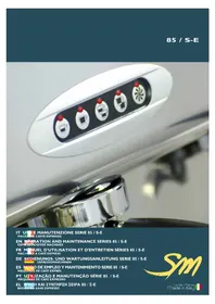
- Index
- Introduction 40
- Description of the machine.. 43
- Installation. pag. 46
- Start-up. pag. 49
- Adjustments.. 49
- Operating instructions.. .51
- Using the display keyboard . 53
- Counter reading.. 58
- Technical level programming.. .59
- Alarm signals.. 63
- Routine maintenance.. 66
- Idle periods.. 67
- Safety devices . 67
- Information for users in the european community.. . 67
- General warranty conditions . 68
- Declaration of conformity C E .pag. 68
- Problem solving.. .69
- Introduction
- Using the manual
- 1.2Warnings
- Installation - warnings
- Use of the machine - warnings
- Maintenance - warnings
- Starting the coffee machine
- Technical characteristics
- Description of the machine
- LEGENDA:
- General water system diagram
- Water system diagram key:
- Installation
- Equipment provided
- Water mains set-up
- FEEDING LINE
- DRAIN LINE
- Water softener (optional)
- Note:
- Installation of water system
- INTERNAL PUMP (OPTIONAL)
- EXTERNAL PUMP
- Drain line
- Electrical connection
- Connection to the equipotential clamp
- Start-up
- Charging the water in the boiler
- Adjustments
- Adjustment of the boiler water level probe
- Calibration of pump pressure
- Adjustment of steam pressure in boiler
- Adjustment of temperature of dispenser groups
- Additional notes for models TOP 85 DTC (Dual Temperature Control)
- Operating instructions
- Serving of espresso coffee
- Programmed dose brewing
- Brewing coffee in START-STOP mode
- The dosing makes it possible to brew coffee in all units at the same time.
- Drawing steam
- Hot water outlet
- PROGRAMMED DOSE
- DISPENSING IN START-STOP MODE
- Automatic washing system
- Cup heater (optional)
- Using the display keyboard
- Programming
- Menu access
- Programming the doses
- Programming the boiler temperature
- Date/time programming
- Programming automatic on/off
- AUTO OFF programming screen.
- Programming day off
- LED RGB cup tray lighting programming
- LED RGB cup tray lighting programming screen.
- Counter reading
- Read total litres count
- Read partial and total single coffee dose count
- Technical level programming
- Software information screen
- Infuser
- Language selection screen
- Display message screen
- Service number setting screen
- Dose change activation screen
- Continuous dose activation screen
- LED RGB cup tray lighting activation screen
- Preinfusion activation screen
- Single dose preinfusion screen
- Number of service intervention cycles screen
- Water softener filter change signal
- Dose deviation screen
- Lower counter alarm limit screen
- Water counter screen
- Default setting reset screen
- Alarm signals
- Faulty counter screen
- Water softener filter replacement screen
- Technical service signalling screen
- Boiler water level alarm signalling screen
- Boiler temperature alarm signalling screen
- Check grinding/dose signalling screen
- Screen 45 Water counter check signalling screen.
- Possible water leak signalling screen
- Screen 46 Possible water leak signalling screen.
- WARNING POSSIBLE LOSS OF WATER
- Volumetric counter alarm
- Autolevel alarm
- Maximum water level in boiler alarm
- Alarm for temperature sensor
- Routine maintenance
- Cleaning the serving units and the filter holder
- Cleaning the tray and the cup support grill
- Cleaning the steam spout
- Substitution of boiler water
- Idle periods
- Safety devices
- Manual reset safety thermostat
- Safety valve
- Information for users in the european community
- General warranty conditions
- Declaration of conformity (€
- Problem solving
- EMPPIOI ET ENTRETIEN SÉRIE TOP 85
- POMPE INTERNE (EN OPTION)
- Evacuation
- DOSE CONTINUE ACTIVER
- La San Marco spa
Brand : La San Marco
Model : Top 85
Category : Coffee machine