
Duale Class - Coffee machine La San Marco - Free user manual and instructions
Find the device manual for free Duale Class La San Marco in PDF.
| Product Type | Professional coffee machine |
| Brand | La San Marco |
| Model | Duale Class |
| Number of groups | 2 or 3 (depending on version) |
| Boiler capacity | 4 L (Duale 2) / 20 L (Duale 3) |
| Weight | 69 kg (Duale 2) / 97 kg (Duale 3) |
| Dimensions (L x H x D) | 780 x 530 x 530 mm (Duale 2) / 970 x 530 x 530 mm (Duale 3) |
| Power consumption | 3500-4500 W (Duale 2) / 5500-7000 W (Duale 3) |
| Electrical supply | Single-phase or three-phase (depending on version) |
| Pump pressure | 9 bar (adjustable) |
| Boiler pressure | 0.9 to 1.2 bar (steam) |
| Ambient temperature | 5 to 45 °C |
| Water hardness | Less than 15 °fH |
| Noise level | Less than 70 dB(A) |
| Main functions | Espresso (lever or electronic), steam, hot water, cup warmer (optional) |
| Dose programming | 4 doses per group (electronic programming) |
| Maintenance and cleaning | Daily cleaning of groups, portafilters, drip tray, steam wand; boiler water change |
| Safety | Manual reset safety thermostat, safety valve (2-2.5 bar) |
| Spare parts and repairability | Use only original La San Marco parts; repair by authorized technician |
| General information | Manual in French, 74 pages; warranty under conditions |
Frequently Asked Questions - Duale Class La San Marco
User questions about Duale Class La San Marco
0 question about this device. Answer the ones you know or ask your own.
Ask a new question about this device
Download the instructions for your Coffee machine in PDF format for free! Find your manual Duale Class - La San Marco and take your electronic device back in hand. On this page are published all the documents necessary for the use of your device. Duale Class by La San Marco.
USER MANUAL Duale Class La San Marco
Translation of the original instructions
Index
- Introduction . 21
1.1 Using the manual . . . . . . . . . . . . . . . . . . . . . . . . . . . . . . . . . . . . . . . . . . . . .
1.2Warnings .pag.21
1.3 Starting the coffee machine.. 23
- Technical characteristics . 23
3.Description of the machine. pag.23
3.1 Diagram of water feed system.. .24
3.2Legend . 24
- Installation.. 25
4.1 Equipment provided.. .25
4.2 Water mains set-up . 26
4.3 Water softener (optional) . 26
4.4 Installation of water system . 26
4.5 Installation of water system with motor pump (optional) . . . . . . . . . . . . . . . . . . . . . . . . . . . . . . . . . . . . . . . . . . . . . . . .
4.6 Drain line . 26
4.7 Electrical connection . . . . . . . . . . . . . . . . . . . . . . . . . . . . . . . . . . . . . . . . . . . . . . .
5.Start-up. pag.27
5.1 Charging the water in the boiler.. . . . . . . . . . . . . . . . . . . . . . . . . . . . . . . . . . . . .
5.2 Heating the water in the boiler.. . 27
5.3 Adjustment of pump serving pressure . 28
5.4 Calibration of steam pressure in boiler . 28
5.5 Automatic operation - programming the coffee brewing cycles . . . . . . . . . . . . . . . . . . . . . . . . . . . . . . . . . . . .
5.6 Alarms . 29
- Operating instructions.. .29
6.1 Dispensing espresso with LEVER unit. 29
6.2 Dispensing coffee with electronic units.. . 30
6.3 Drawing steam.. 30
6.4 Drawing hot water . 30
6.5 Cup heater (optional) . 30
- Routine maintenance.. .30
7.1 Cleaning the serving units and the filter holder . 31
7.2 Cleaning the tray and the cup support grill . 31
7.3 Cleaning the steam spout . 31
7.4 Substitution of boiler water . 31
-
Idle periods.. .pag. 31
-
Safety devices . 31
9.1 Manual reset safety thermostat . . . . . . . . . . . . . . . . . . . . . . . . . . . . . . . . . . . . . . . . . . . . . . . . . . . . . . . .
9.2 Safety valve . 32
- Information for users in the european community . . . . . . . . . . . . . . . . . . . . . . . . . .
11.Guarantee. . 32 - Declaration of conformity C E .pag. 32
- Problem solving.. 33
1. Introduction

Before using the machine, carefully read all of the instructions contained in this machine.
1.1 Using the manual

This manual contains all information required for the installation, use and maintenance of the coffee machine.
This manual is an integral part of the machine; always keep it intact together with the appliance.
1.2Warnings

Mandatory Requirements: the operation of the lever for coffee brewing, it is extremely dangerous. In order to avoid the risk of harm to the operator is absolutely necessary, before driving the lever for any reason, make sure that:
- the filter holder cup is completely filled with the right amount of coffee,
- the cup is safely and properly coupled to the coffee brewing unit and
- the coffee machine is regularly and properly connected to the network's national water, with the water shutoff valve fully open.
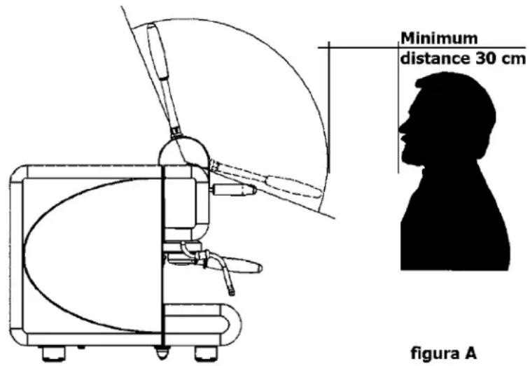
It 'still strict obligatory for the user of the lever machine keeping the body at a minimum distance of 30 cm from the range of lever's action when the lever is operating, as well as shown in Figure A.

The manufacturer declines all responsibilities for any damage occurring to persons and / or property due to negligent behaviour by the user that does not comply with the mandatory requirements contained in this manual.
Should the cup not properly couple the group brewing unit, is strictly forbidden to continue to use the machine in such conditions and it is imperative to contact your nearest authorized service center or the manufacturer, La San Marco SpA.
- Do not operate the machine or carry out routine maintenance before reading this manual.
- This machine is designed and built for serving espresso coffee, hot water (for the preparation of beverages and infusions) and steam (used to heat liquids). The use of the machine for any other than its intended purposes is considered to be improper and unauthorized. The manufacturer declines any liability for damage resulting from the improper use of the machine.
- This machine must be installed only in places where its use and its maintenance are made by trained personnel.
- The device must be connected to the local water mains using a flexible pipe fitting in compliance with national standards, if these are applicable. Furthermore, the equipment must be installed with suitable "reflux protection" in order to comply with the applicable national and local regulations.
Install the machine on a plane at a height of not less than 800 mm above the floor.
The scheduled maintenance and repair should only be performed by authorized and qualified personnel.
- Do not install the espresso coffee machine in places where cleaning is likely to be carried out with jets of water. Do not immerge the unit in water to clean it.
If the power cord is damaged its replacement should be performed only by authorized and qualified personnel.
- The user must be a responsible adult, who is expected to comply with local safety accepted common sense procedures. For a proper and safe use of the machine, the operator must always comply with applicable accident prevention and other work safety and health regulations.
- This appliance is not designed for use by persons (including children) with limited physical, sensory or mental abilities, or lacking in experience and knowledge, unless they are controlled and taught to use the appliance by a person responsible for their safety. Children must be supervised to make sure they do not play with the appliance.
- The use of the appliance and the routine maintenance and cleaning operations may only be carried out by authorized personnel, under the responsibility of the client.
- The machine must never be switched on before connecting it to the water supply. The user must make sure that the water supply valve remains open when the machine is switched on. Place only empty cups in the cup holding shelf.
- The machine in operation must never be covered, as there must be a proper air circulation around it.
- The machine must never be used with the fixed and/or mobile guards removed or with the safety devices cut off. The safety devices must absolutely never be removed or tampered with. The panels covering the machine must not be removed, as the machine contains live parts (there is the risk of electric shock).
- Before carrying out any machine cleaning or maintenance operations, unplug the power cable, if possible, or disconnect the omnipolar switch upstream of the machine.
The safety devices must always be in a perfectly efficient state, as regularly maintain authorized La San Marco service personnel.
- The hot parts of the machine (serving units, boiler, piping, etc.) can cause serious burns due to accidental contact with the skin. It is therefore necessary to use safety gloves, aprons, etc., during maintenance or repair operations.
- When cleaning the machine, avoid using products such as alcohol, petrol or solvents in general; use water or neutral detergents.
- To clean the machine frame, it is sufficient to use a moist cloth or a sponge. Avoid using abrasive products that could damage the elements on the body. To clean the coffee serving units, the filtering cups, the grills and the trays, follow the instructions of the Routine Maintenance chapter.
- For better product quality, replace the hot water in the boiler and circulate the water in the pipes upon first turning the machine on in the morning. If the machine is expected to remain idle for a few hours during the day, we also recommend changing the water by running it through the hot water tap and the coffee serving units.
- Strict compliance with the routine maintenance instructions of this manual is required for a safe and efficient operation of the appliance.
- In case of malfunctions or failure of any machine component, contact the authorized service centre and request original La San Marco spare parts. The use of any other than original spare parts voids the conformity certifications and the warranty that accompany the machine.
- Any changes carried out on the machine and/or failure to carry out the scheduled maintenance will release the Manufacturer from any liability for any resulting damages and voids the conformity declaration and the warranty.
- Unauthorised operations or operations whose methods of execution are not exactly clear or unauthorised interventions on the machine are strictly prohibited; contact the manufacturer for information, spare parts or accessories that you may need.
- Should the appliance be moved outdoors or to premises where the temperature might drop below 0ircC , it is vital that the exchangers circuit be emptied, cutting off the water supply to the appliance and draining all water from the units until they only emit steam. Omitting to perform this procedure could lead to the exchangers breaking, due to the water inside them freezing.
- For a proper disposal of the machine when it is to be discarded, contact the supplier or the authorized firms specialized in the collection and disposal of solid urban waste. Do not discard the appliance in the environment.
- La San Marco S.p.A. reserves the right to make any technical changes on the machine considered necessary without advance notice.
1.3 Starting the coffee machine
Ambient temperature: 5 ÷ 45irc C (drain the water system in case of frost)
Water pressure: 80 ÷ 900kPa (0.8 ÷ 9.0 bar)
Water hardness: less than 5irc f
Noise level emitted by the machine: The weighted sound pressure level A is below 70 db(A), under normal conditions of use of the machine.
2. Technical characteristics
| DUALE CLASS | COFFEE SERVING UNITS COFFEE SERVING UNITS DTC (OPTIONAL) COFFEE SERVING UNITS LEVER | STEW WANDS | HOT WATER WANDS | BOILER CAPACITY (L) | WEIGHT (KG) | HEIGHT (CM) | WIDTH (CM) | DEPTH (CM) | INSTALLED POWER (W) | |||||||||
| BOILER HEATING ELEMENT | EXTERNAL MOTOR PUMP | CUP HEATER (OPTIONAL) | ||||||||||||||||
| MONO-PHASE | TREE-PHASE | |||||||||||||||||
| DUALE 2 | 1 | 1 | 2 | 1 | 4 | 69 | 78 | 80 | 5 | 3 | 3500 | /4500 | 300 | 1 | 00 | |||
| DUALE 3 | 2 | 2 | 1 | 2 | 1 | 2 | 1 | 20 | 7 | 20 | 74 | 97 | 80 | 53 | 5500 / 7000 | 300 | 125 | |
| OPTIONAL: WATER SOFTENER; MILK FROther; AUTOSTeam; THROTTLE STEAM; LED LIGHT WORKING SURFACE SYSTEM. | ||||||||||||||||||
3. Description of the machine
Note: The terms used in this description will commonly be used throughout the following pages.

3.1 Diagram of water feed system

3.2 Legend
- Main switch
- Main switch indicator light
- Steam spout
- Espresso dispensing unit with lever actuation
- Lever of tap for drawing steam
- Lever for coffee serving
- Hot water supply cock handle
- Coffee dispensing unit with electronic control
- Filter holding cup with handle
- Manual boiler water filling lever
- Hot water spout
-
- Boiler pressure gauge
- Visual level indicator
- Boiler water drain tap
- Automatic level tap (optional)
- Push button valve with check valve
- Automatic level tap (optional)
- No-return and safety valve
- Automatic level solenoid (optional)
- Pressure switch
- Pressure switch setting screw
- Grounds collecting tray
- Drain pipe
- Water softener (optional)
- Water softener feeding pipe
- Mains water supply tap
- Mains water supply pipe
- Pump feeding pipe
- Machine feeding pipe
- Motor pump (optional - suggested on models with autofill)
a. Single short coffee supply button
b. Single long coffee supply button
c. Double short coffee supply button
d. Double long coffee supply button
e. Continuous supply button
4. Installation

Mandatory Requirements: the operation of the lever for coffee brewing, it is extremely dangerous. In order to avoid the risk of harm to the operator is absolutely necessary, before driving the lever for any reason, make sure that:
- the filter holder cup is completely filled with the right amount of coffee,
- the cup is safely and properly coupled to the coffee brewing unit and
- the coffee machine is regularly and properly connected to the network's national water, with the water shutoff valve fully open.
It 'still strict obligatory for the user of the lever machine keeping the body at a minimum distance of 30 cm from the range of lever's action when the lever is operating, as well as shown in Figure A.

The manufacturer declines all responsibilities for any damage occurring to persons and / or property due to negligent behaviour by the user that does not comply with the mandatory requirements contained in this manual.
Should the cup not properly couple the group brewing unit, is strictly forbidden to continue to use the machine in such conditions.
- The installation must be carried out by authorized La San Marco technical personnel.
- The coffee machine is delivered in a suitable packing. The packing contains the machine and its accessories, the user manual and the conformity declaration. After opening the packing, check the proper condition of the coffee machine and its components. In case of doubt, do not use the appliance, and contact La San Marco S.p.A.
All of the packaging must be carefully conserved in case the machine needs to be transported in the future. - The machine should be placed on a perfectly horizontal plane sufficiently sturdy to support the weight of the machine, with a sufficient clearance around it to dissipate the heat generated during its operation.
- Do not install the espresso coffee machine in places where cleaning is likely to be carried out with jets of water. Do not immerge the unit in water to clean it.
- For safety against hazards related to electrical currents, keep the machine away from sinks, tubs, aquar
uums, taps, and areas that are wet or where water may splash. - The machine creates heat. Therefore it needs to be placed in a room that is sufficiently ventilated to ensure heat dissipation. Keep the machine away from sources of direct heat.
- Make sure that the voltage of the power socket does not differ from that indicated on the technical data and on the identification tag on the machine. If the voltage is different, do not connect the machine. This may be dangerous and may damage the unit.
- If the voltage is found to be different, do not connect the machine as this could be dangerous and could damage the device.
4.1 Equipment provided
The machine packing contains the equipment kit, which includes the following items:
- filter cups with filter restraint ring
- filters for filter cups (single and double doses)
- blind filter for filter cup
-
spouts for filter cups (single and double doses)
-
press for ground coffee
- rubber tube with stainless steel mesh for water connection (water circuit - water softener)
- rubber drain hose with steel coil for water drain
- 3/8" nipples for hose connection to water supply tube
- cleaning brush for serving units
water filter before pump (on request) - rubber tube with stainless steel mesh of 600mm for water connection (water circuit - water softener)
- rubber tube with stainless steel mesh of 1600mm for water connection (water circuit - water softener)
4.2 Water mains set-up
FEEDING LINE
Bring the water feeding tube (of at least 3/8 diameter) up to the machine and install an on-off valve (preferably of 3/8 ball type) that allows a rapid opening and closing operation. The machine should be connected to the water mains using the tube supplied with it. Do not connect the machine with used tubes.
DRAIN LINE
Provide an inspeectable drainage pit on the floor connected with the sink drainage line, suitable for receiving the machine gravity drainage tube. The drain tube must be positioned so that the water flows out freely, without possibility for the pipe to clog up during the operation.
4.3 Water softener (optional)

The water softener for softening the mains water can be manual or automatic, depending on customer's request.

Before connecting the water softener to the coffee machine, the resins contained in it should be washed off as described in the user's manual supplied with the appliance.
Note:
The water softener is considered an essential device to guarantee a proper operation of the espresso coffee machine. A water softening system should be provided in order to guarantee the efficiency, performance and duration of the components in the machine.
4.4 Installation of water system
1) Use the pipe 32 (900 mm, provided with the machine) to connect the cut-off valve of the mains to the tap for water inlet to the water softener (figure 1).
2) Connect pipe 36 (1600 mm, provided with the machine) to the tap of water softener with the tap of the coffee machine water system (figura 2-3).


Figure 1 Figure 2 Figure 4
32 36 36
4.5 Installation of water system with motor pump (optional)
1) Use the pipe 32 (900 mm, provided with the machine) to connect the cut-off valve of the mains to the tap for water inlet to the water softener (figure 1).
2) Connect the pipe 35 (600 mm, provided with the machine) for pump suction (see diagram of water feed system) to the tap of the coffee machine water system (figure 3).
4.6 Drain line
Connect the drainage tube to the grounds collecting tray and to the water drainage system.
4.7 Electrical connection

Instructions for a proper electrical connection of the espresso coffee machine:
-
Before connecting the unit to the electrical mains, make sure that the data on the data plate corresponds to the electrical mains.
-
The tag is located on the left side of the machine (and can be accessed by removing the lower tray).
- The electrical system provided by the client must comply with current standards. The power socket must be equipped with a working earth connection. LA SAN MARCO SPA will not in any way be held liable if legal requirements are not met. An improper installation can cause injury or damage for which the manufacturer cannot be held liable.
- For the electrical connection, it is necessary to install an omnipolar main switch upstream of the power supply; this switch should be rated according to the electrical characteristics (power and voltage) shown on the rating tag. The omnipolar switch must disconnect the power supply with a contact gap of at least 3mm .
- If it is necessary to use adapters, multiple plugs and extensions, only products meeting applicable safety standards must be used.
- To avoid any overheating of the power cable, unwind it completely. Connect the power cord to the electrical mains as shown in the attached diagram:
| DUALE NOTE: * The power absorbed by the electric heating elements can be reduced to 2/3 by joining the BLACK wire with the GRAY one. | 230V MONO-PHASE* 400V-3N THREE-PHASE N BLUE GREY BLACK BROWN YE / GR L3 GREY L2 BLACK L1 BROWN YE / GR L1 GREY L2 GREY L1 BROWN YE / GR L1 GREY L2 GREY L1 BROWN YE / GR L1 GREY L2 GREY L1 BROWN YE / GR L1 GREY L2 GREY L1 BROWN YE / GR L1 GREY L2 GREY L1 BROWN YE / GR L1 GREY L2 GREY L1 BROW L2 GREY L1 BROWN YE / GR L1 GREY L2 GREY L1 BROWN YE / GR L1 GREY L2 GREY L1 BROWN YE / GR L1 GREY L2 GREY L1 BROWN YE / GR L1 GREY L2 GREY L1 BROWN YE / GR L1 GREY L2 GREy L1 BROWN YE / GR L1 GREY L2 GREY L1 BROWN YE / GR L1 GREY L2 GREY L1 BROWN YE / GR L1 GREY L2 GREY L1 BROWN YE / GR L1 GREY L2 GREY L1 BROWN YE / GR L1 GREY L2 GREY L1 BBrown L2 GREY L1 BROWN YE / GR L1 GREY L2 GREY L1 BROWN YE / GR L1 GREY L2 GREY L1 BROWN YE / GR L1 GREY L2 GREY L1 BROWN YE / GR L1 GREY L2 GREY L1 BROWN YE / GR L1 GREY L2 GREV L1 BROWN YE / GR L1 GREY L2 GREY L1 BROWN YE / GR L1 GREY L2 GREY L1 BROWN YE / GR L1 GREY L2 GREY L1 BROWN YE / GR L1 GREY L2 GREY L1 BROWN YE / GR L1 GREY L2 GREY L1 B brown L2 GREY L1 BROWN YE / GR L1 GREY L2 GREY L1 BROWN YE / GR L1 GREY L2 GREY L1 BROWN YE / GR L1 GREY L2 GREY L1 BROWN YE / GR L1 GREY L2 GREY L1 BROWN YE / GR L1 GREY L2 GRE Y L1 BROWN YE / GR L1 GREY L2 GREY L1 BROWN YE / GR L1 GREY L2 GREY L1 BROWN YE / GR L1 GREY L2 GREY L1 BROWN YE / GR L1 GREY L2 GREY L1 BROWN YE / GR L1 GREY L2 GREY L1 Bbrown L2 GREY L1 BROWN YE / GR L1 GREY L2 GREY L1 BROWN YE / GR L1 GREY L2 GREY L1 BROWN YE / GR L1 GREY L2 GREY L1 BROWN YE / GR L1 GREY L2 GREY L1 BROWN YE / GR L1 GREY L2 GRER L1 BROWN YE / GR L1 GREY L2 GREY L1 BROWN YE / GR L1 GREY L2 GREY L1 BROWN YE / GR L1 GREY L2 GREY L1 BROWN YE / GR L1 GREY L2 GREY L1 BROWN YE / GR L1 GREY L2 GREY L1 B Brown L2 GREY L1 BROWN YE / GR L1 GREY L2 GREY L1 BROWN YE / GR L1 GREY L2 GREY L1 BROWN YE / GR L1 GREY L2 GREY L1 BROWN YE / GR L1 GREY L2 GREY L1 BROWN YE / GR L1 GREY L2 GREW L1 BROWN YE / GR L1 GREY L2 GREY L1 BROWN YE / GR L1 GREY L2 GREY L1 BROWN YE / GR L1 GREY L2 GREY L1 BROWN YE / GR L1 GREY L2 GREY L1 BROWN YE / GR L1 GREY L2 GREY L1 BONW YE / GR L1 GREY L2 GREY L1 BONW YE / GR L1 GREY L2 GREY L1 BONW YE / GR L1 GREY L2 GREY L1 BONW YE / GR L1 GREY L2 GREY L1 BONW YE / GR L1 GREY L2 GREY L1 BONw YE / GR L1 GREY L2 GREY L1 BONW YE / GR L1 GREY L2 GREY L1 BONW YE / GR L1 GREY L2 GREY L1 BONW YE / GR L1 GREY L2 GREY L1 BONW YE / GR L1 GREY L2 GREY L1 BON W YE / GR L1 GREY L2 GREY L1 BONW YE / GR L1 GREY L2 GREY L1 BONW YE / GR L1 GREY L2 GREY L1 BONW YE / GR L1 GREY L2 GREY L1 BONW YE / GR L1 GREY L2 GREY L1 BON W L2 GREY L3 GREY L4 GREY L5 GREY L6 GREY L7 GREY L8 GREY L9 GREY L10 GREY L11 GREY L12 GREY L13 GREY L14 GREY L15 GREY L16 GREY L17 GREY L18 GREY L19 GREY L20 GREY L21 GREY L22 GREY L23 GREY L24 GREY L25 GREY L26 GREY L27 GREY L28 GREY L29 GREY L30 GREY L31 GREY L32 GREY L33 GREY L34 GREY L35 GREY L36 GREY L37 GREY L38 GREY L39 GREY L40 GREY L41 GREY L42 GREY L43 GREY L44 GREY L45 GREY L46 GREY L47 GREY L48 GREY L49 GREY L50 GREY L51 GREY L52 GREY L53 GREY L54 GREY L55 GREY L56 GREY L57 GREY L58 GREY L59 GREY L60 GREY L61 GREY L62 GREY L63 GREY L64 GREY L65 GREY L66 GREY L67 GREY L68 GREY L69 GREY L70 GREY L71 GREY L72 GREY L73 GREY L74 GREY L75 GREY L76 GREY L77 GREY L78 GREY L79 GREY L80 GREY L81 GREY L82 GREY L83 GREY L84 GREY L85 GREY L86 GREY L87 GREY L88 GREY L89 GREY L90 GREY L91 GREY L92 GREY L93 GREY L94 GREY L95 GREY L96 GREY L97 GREY L98 GREY L99 GREY L100 GREY L101 GREY L102 GREY L103 GREY L104 GREY L105 GREY L106 GREY L107 GREY L108 GREY L109 GREY L110 GREY L111 GREY L112 GREY L113 GREY L114 GREY L115 GREY L116 GREY L117 GREY L118 GREY L119 GREY L120 GREY L121 GREY L122 GREY L123 GREY L124 GREY L125 GREY L126 GREY L127 GREY L128 GREY L129 GREY L130 GREY L131 GREY L132 GREY L133 GREY L134 GREY L135 GREY L136 GREY L137 GREY L138 GREY L139 GREY L140 GREY L141 GREY L142 GREY L143 GREY L144 GREY L145 GREY L146 GREY L147 GREY L148 GREY L149 GREY L150 GREY L151 GREY L152 GREY L153 GREY L154 GREY L155 GREY L156 GREY L157 GREY L158 GREY L159 GREY L160 GREY L161 GREY L162 GREY L163 GREY L164 GREY L165 GREY L166 GREY L167 GREY L168 GREY L169 GREY L170 GREY L171 GREY L172 GREY L173 GREY L174 GREY L175 GREY L176 GREY L177 GREY L178 GREY L179 GREY L180 GREY L181 GREY L182 GREY L183 GREY L184 GREY L185 GREY L186 GREY L187 GREY L188 GREY L189 GREY L190 GREY L191 GREY L192 GREY L193 GREY L194 GREY L195 GREY L196 GREY L197 GREY L198 GREY L199 GREY L200 GREY L201 GREY L202 GREY L203 GREY L204 GREY L205 GREY L206 GREY L207 GREY L208 GREY L209 GREY L210 GREY L211 GREY L212 GREY L213 GREY L214 GREY L215 GREY L216 GREY L217 GREY L218 GREY L219 GREY L220 GREY L221 GREY L222 GREY L223 GREY L224 GREY L225 GREY L226 GREY L227 GREY L228 GREY L229 GREY L230 GREY L231 GREY L232 GREY L233 GREY L234 GREY L235 GREY L236 GREY L237 GREY L238 GREY L239 GREY L240 GREY L241 GREY L242 GREY L243 GREY L244 GREY L245 GREY L246 GREY L247 GREY L248 GREY L249 GREY L250 GREY L251 GREY L252 GREY L253 GREY L254 GREY L255 GREY L256 GREY L257 GREY L258 GREY L259 GREY L260 GREY L261 GREY L262 GREY L263 GREY L264 GREY L265 GREY L266 GREY L267 GREY L268 GREY L269 GREY L270 GREY L271 GREY L272 GREY L273 GREY L274 GREY L275 GREY L276 GREY L277 GREY L278 GREY L279 GREY L280 GREY L281 GREY L282 GREY L283 GREY L284 GREY L285 GREY L286 GREY L287 GREY L288 GREY L289 GREY L290 GREY L291 GREY L292 GREY L293 GREY L294 GREY L295 GREY L296 GREY L297 GREY L298 GREY L299 GREY L300 GREY L301 GREY L302 GREY L303 GREY L304 GREY L305 GREY L306 GREY L307 GREY L308 GREY L309 GREY L310 GREY L311 GREY L312 GREY L313 GREY L314 GREY L315 GREY L316 GREY L317 GREY L318 GREY L319 GREY L320 GREY L321 GREY L322 GREY L323 GREY L324 GREY L325 GREY L326 GREY L327 GREY L328 GREY L329 GREY L330 GREY L331 GREY L332 GREY L333 GREY L334 GREY L335 GREY L336 GREY L337 GREY L338 GREY L339 GREY L340 GREY L341 GREY L342 GREY L343 GREY L344 GREY L345 GREY L346 GREY L347 GREY L348 GREY L349 GREY L350 GREY L351 GREY L352 GREY L353 GREY L354 GREY L355 GREY L356 GREY L357 GREY L358 GREY L359 GREY L360 GREY L361 GREY L362 GREY L363 GREY L364 GREY L365 GREY L366 GREY L367 GREY L368 GREY L369 GREY L370 GREY L371 GREY L372 GREY L373 GREY L374 GREY L375 GREY L376 GREY L377 GREY L378 GREY L379 GREY L380 GREY L381 GREY L382 GREY L383 GREY L384 GREY L385 GREY L386 GREY L387 GREY L388 GREY L389 GREY L390 GREY L391 GREY L392 GREY L393 GREY L394 GREY L395 GREY L396 GREY L397 GREY L398 GREY L399 GREY L400 GREY L401 GREY L402 GREY L403 GREY L404 GREY L405 GREY L406 GREY L407 GREY L408 GREY L409 GREY L410 GREY L411 GREY L412 GREY L413 GREY L414 GREY L415 GREY L416 GREY L417 GREY L418 GREY L419 GREY L420 GREY L421 GREY L422 GREY L423 GREY L424 GREY L425 GREY L426 GREY L427 GREY L428 GREY L429 GREY L430 GREY L431 GREY L432 GREY L433 GREY L434 GREY L435 GREY L436 GREY L437 GREY L438 GREY L439 GREY L440 GREY L441 GREY L442 GREY L443 GREY L444 GREY L445 GREY L446 GREY L447 GREY L448 GREY L449 GREY L450 GREY L451 GREY L452 GREY L453 GREY L454 GREY L455 GREY L456 GREY L457 GREY L458 GREY L459 GREY L460 GREY L461 GREY L462 GREY L463 GREY L464 GREY L465 GREY L466 GREY L467 GREY L468 GREY L469 GREY L470 GREY L471 GREY L472 GREY L473 GREY L474 GREY L475 GREY L476 GREY L477 GREY L478 GREY L479 GREY L480 GREY L481 GREY L482 GREY L483 GREY L484 GREY L485 GREY L486 GREY L487 GREY L488 GREY L489 GREY L490 GREY L491 GREY L492 GREY L493 GREY L494 GREY L495 GREY L496 GREY L497 GREY L498 GREY L499 GREY L500 GREY L501 GREY L502 GREY L503 GREY L504 GREY L505 GREY L506 GREY L507 GREY L508 GREY L509 GREY L510 GREY L511 GREY L512 GREY L513 GREY L514 GREY L515 GREY L516 GREY L517 GREY L518 GREY L519 GREY L520 GREY L521 GREY L522 GREY L523 GREY L524 GREY L525 GREY L526 GREY L527 GREY L528 GREY L529 GREY L530 GREY L531 GREY L532 GREY L533 GREY L534 GREY L535 GREY L536 GREY L537 GREY L538 GREY L539 GREY L540 GREY L541 GREY L542 GREY L543 GREY L544 GREY L545 GREY L546 GREY L547 GREY L548 GREY L549 GREY L550 GREY L551 GREY L552 GREY L553 GREY L554 GREY L555 GREY L556 GREY L557 GREY L558 GREY L559 GREY L560 GREY L561 GREY L562 GREY L563 GREY L564 GREY L565 GREY L566 GREY L567 GREY L568 GREY L569 GREY L570 GREY L571 GREY L572 GREY L573 GREY L574 GREY L575 GREY L576 GREY L577 GREY L578 GREY L579 GREY L580 GREY L581 GREY L582 GreY L583 GreY L584 GreY L585 GreY L586 GreY L587 GreY L588 GreY L589 GreY L590 GreY L591 GreY L592 GreY L593 GreY L594 GreY L595 GreY L596 GreY L597 GreY L598 GreY L599 GreY L600 GreY L601 GreY L602 GreY L603 GreY L604 GreY L605 GreY L606 GreY L607 GreY L608 GreY L609 GreY L610 GreY L611 GreY L612 GreY L613 GreY L614 GreY L615 GreY L616 GreY L617 GreY L618 GreY L619 GreY L620 GreY L621 GreY L622 GreY L623 GreY L624 GreY L625 GreY L626 GreY L627 GreY L628 GreY L629 GreY L630 GreY L631 GreY L632 GreY L633 GreY L634 GreY L635 GreY L636 GreY L637 GreY L638 GreY L639 GreY L640 GreY L641 GreY L642 GreY L643 GreY L644 GreY L645 GreY L646 GreY L647 GreY L648 GreY L649 GreY L650 GreY L651 GreY L652 GreY L653 GreY L654 GreY L655 GreY L656 GreY L657 GreY L658 GreY L659 GreY L660 GreY L661 GreY L662 GreY L663 GreY L664 GreY L665 GreY L666 GreY L667 GreY L668 GreY L669 GreY L670 GreY L671 GreY L672 GreY L673 GreY L674 GreY L675 GreY L676 GreY L677 GreY L678 GreY L679 GreY L680 GreY L681 GreY L682 GreY L683 GreY L684 GreY L685 GreY L686 GreY L687 GreY L688 GreY L689 GreY L690 GreY L691 GreY L692 GreY L693 GreY L694 GreY L695 GreY L696 GreY L697 GreY L698 GreY L699 GreY L700 GreY L701 GreY L702 GreY L703 GreY L704 GreY L705 GreY L706 GreY L707 GreY L708 GreY L709 GreY L710 GreY L711 GreY L712 GreY L713 GreY L714 GreY L715 GreY L716 GreY L717 GreY L718 GreY L719 GreY L720 GreY L721 GreY L722 GreY L723 GreY L724 GreY L725 GreY L726 GreY L727 GreY L728 GreY L729 GreY L730 GreY L731 GreY L732 GreY L733 GreY L734 GreY L735 GreY L736 GreY L737 GreY L738 GreY L739 GreY L740 GreY L741 GreY L742 GreY L743 GreY L744 GreY L745 GreY L746 GreY L747 GreY L748 GreY L749 GreY L750 GreY L751 GreY L752 GreY L753 GreY L754 GreY L755 GreY L756 GreY L757 GreY L758 GreY L759 GreY L760 GreY L761 GreY L762 GreY L763 GreY L764 GreY L765 GreY L766 GreY L767 GreY L768 GreY L769 GreY |
5. start-up

-
The coffee machine must be started by qualified technical personnel approved by La San Marco.
-
Once the electric and hydraulic connections are completed, the user is urged to start the espresso coffee machine with the following procedure in order to avoid damaging the appliance.
5.1 Charging the water in the boiler
1) Check that the machine main switch 1 (figure 1) is in position 0 (zero).
2) Remove the tray and the cup support grill and make sure that:
a) The boilerdrain valve 21 is closed.
b) The taps of automatic level valve 22-24 must be open.
3) Open the water supply on-off valve 33.
4) Open a steaming tap 5 to allow the exit of the air in the boiler filling phase.
5) Reinstall the tray and cup support grill in its place.
6) Press and hold down the button 10 until the sight glass 20 is 34 full.
5.2 Heating the water in the boiler
1) Rotate the main switch to position 2.
2) Hold down a steam delivery lever 5 to allow air to escape from the system as the machine heats up. Release the lever as soon as steam escapes from the delivery pipe. Boiler pressure is indicated on the 0 ÷ 3 bar scale on the pressure gauge 14 (suggested value: 0.9 ÷ 1.2 bar).
5.3 Adjustment of pump serving pressure
a. Once the boiler is filled, turn the main switch to position 2 (the heating elements start to heat the water).
b. Press the continuous-feeding push button 18 for the manual serving machines or the push button 10 for the electronic machines with automatic serving, so that the water flows out of the unit the corresponding to the pressed button.
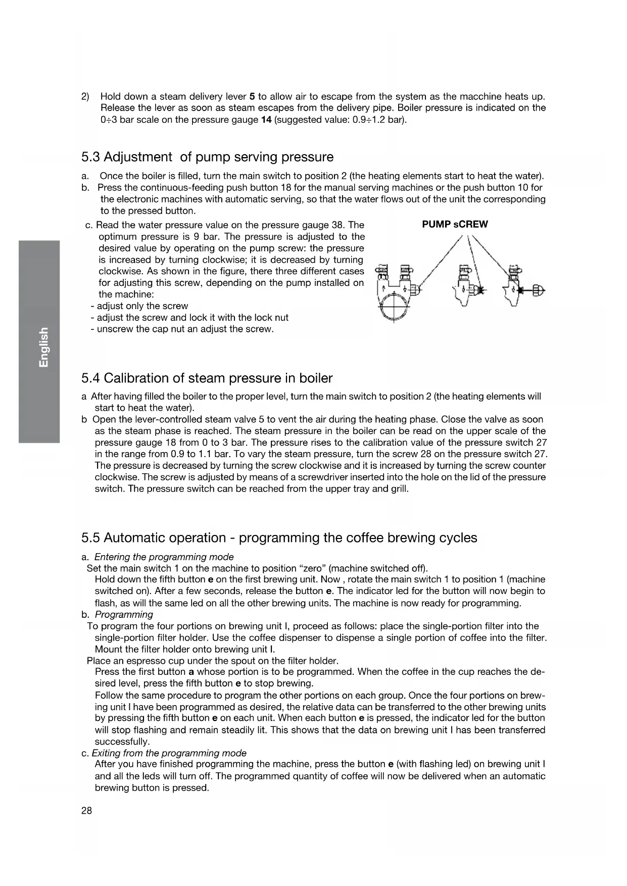
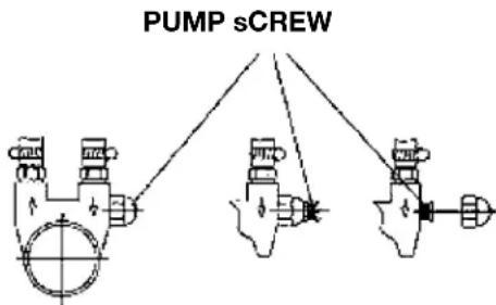
c. Read the water pressure value on the pressure gauge 38. The optimum pressure is 9 bar. The pressure is adjusted to the desired value by operating on the pump screw: the pressure is increased by turning clockwise; it is decreased by turning clockwise. As shown in the figure, there three different cases for adjusting this screw, depending on the pump installed on the machine:
- adjust only the screw
- adjust the screw and lock it with the lock nut
- unscrew the cap nut an adjust the screw.
5.4 Calibration of steam pressure in boiler
a After having filled the boiler to the proper level, turn the main switch to position 2 (the heating elements will start to heat the water).
b Open the lever-controlled steam valve 5 to vent the air during the heating phase. Close the valve as soon as the steam phase is reached. The steam pressure in the boiler can be read on the upper scale of the pressure gauge 18 from 0 to 3 bar. The pressure rises to the calibration value of the pressure switch 27 in the range from 0.9 to 1.1 bar. To vary the steam pressure, turn the screw 28 on the pressure switch 27. The pressure is decreased by turning the screw clockwise and it is increased by turning the screw counter clockwise. The screw is adjusted by means of a screwdriver inserted into the hole on the lid of the pressure switch. The pressure switch can be reached from the upper tray and grill.
5.5 Automatic operation - programming the coffee brewing cycles
a. Entering the programming mode
Set the main switch 1 on the machine to position "zero" (machine switched off).
Hold down the fifth button e on the first brewing unit. Now, rotate the main switch 1 to position 1 (machine switched on). After a few seconds, release the button e. The indicator led for the button will now begin to flash, as will the same led on all the other brewing units. The machine is now ready for programming.
b. Programming
To program the four portions on brewing unit I, proceed as follows: place the single-portion filter into the single-portion filter holder. Use the coffee dispenser to dispense a single portion of coffee into the filter. Mount the filter holder onto brewing unit I.
Place an espresso cup under the spout on the filter holder.
Press the first button a whose portion is to be programmed. When the coffee in the cup reaches the desired level, press the fifth button e to stop brewing.
Follow the same procedure to program the other portions on each group. Once the four portions on brewing unit I have been programmed as desired, the relative data can be transferred to the other brewing units by pressing the fifth button e on each unit. When each button e is pressed, the indicator led for the button will stop flashing and remain steadily lit. This shows that the data on brewing unit I has been transferred successfully.
c. Exiting from the programming mode
After you have finished programming the machine, press the button e (with flashing led) on brewing unit I and all the leds will turn off. The programmed quantity of coffee will now be delivered when an automatic brewing button is pressed.
5.6 Alarms
Led on the first button of pushbutton array indicates a malfunction on the flow meter.
A flashing Led on the second button of all the pushbutton arrays indicates a malfunction on the automatic boiler refill A flashing system (jammed solenoid valve, insufficient water from the main water system, etc.). After 1 '30", the pump motor will shut down.
Note: If the machine shuts down as described above, call your local service technician.

-
Do not use water sprays, steam or similar cleaning methods. Before cleaning or maintenance operations, DISCONNECT THE CABLE IF POSSIBLE; OTHERWISE, SHUT OFF THE OMNIPO-LAR MASTER SWITCH INSTALLED AHEAD OF THE MACHINE.
-
If power cable is damaged, it must be replaced with the specially prepared, original equipment replacement part which conforms to safety regulations.
- Special maintenance, parts replacement, long-term shutdown and displanting operations must be performed by LA SAN MARCO service personnel.
6. Operating instructions

During the flow of espresso coffee, tea or steam, these substances can cause burns due to accidental skin contact.
6.1 Dispensing espresso with LEVER unit.
1) Remove the filter-holding cup from the serving unit and fill it with a dose of ground coffee (filter cup with one spout) or with two doses of ground coffee (filter cup with two spouts). Press the ground coffee using the relative coffee presser and then insert the filter cup into the serving unit.
2) Place one or two cups under the serving spouts.
3) Pull down the lever 6 and then let it return to its original position. The coffee will begin to flow after a short time. To obtain a greater quantity of coffee repeat this operation.

Mandatory Requirements: the operation of the lever for coffee brewing, it is extremely dangerous. In order to avoid the risk of harm to the operator is absolutely necessary, before driving the lever for any reason, make sure that:
- the filter holder cup is completely filled with the right amount of coffee,
- the cup is safely and properly coupled to the coffee brewing unit and
- the coffee machine is regularly and properly connected to the network's national water, with the water shutoff valve fully open.
It 'still strict obligatory for the user of the lever machine keeping the body at a minimum distance of 30 cm from the range of lever's action when the lever is operating, as well as shown in Figure A.
The manufacturer declines all responsibilities for any damage occurring to persons and / or property due to negligent behaviour by the user that does not comply with the mandatory requirements contained in this manual.
Should the cup not properly couple the group brewing unit, is strictly forbidden to continue to use the machine in such conditions and it is imperative to contact your nearest authorized service center or the manufacturer, La San Marco SpA.
Note: Make sure that serving into the cup has taken place correctly. If serving has not occurred correctly, see the chapter "PROBLEMS AND SOLUTIONS".
6.2 Dispensing coffee with electronic units.
Make sure that the filter on the cup 13 be of the selected grammage. It is important that dosed and pressed coffee touches the shower of group 12. To check this, simply attach the cup filter holder to the group and remove. If the coffee is at the right level must remain the imprint of the central fixing screw. Once the filter holder has been installed onto the machine, press one of the five brewing buttons. The first two buttons are used to select the two pre-programmed single portions of coffee. The second two buttons are used to select the two pre-programmed double portions of coffee. The fifth button immediately shuts down brewing if pressed during a coffee brewing cycle. This last button can also be used to brew the desired quantity of coffee manually: press this button to start brewing, and press the button a second time to stop brewing when the desired quantity of coffee has been obtained.
6.3 Drawing steam
A jet of steam, which can be used to foam milk or to heat other liquids, comes out of the steam drawing spout as follows: by raising or lowering the lever 5 you attain the maximum flow (the lever stops in the maximum position. To stop the flow of steam, place the lever back in its original position).

The steamer must be used with care: the contact of the skin with the steam spout or with the jet of steam itself can cause serious burns. Grip the anti-burn sheath to change the position of the steam drawing spout. Never aim the jet of steam at persons or at objects which do not have to do with the use as described in this manual.
Note: Before using the spout for drawing steam, drain out into the tub any condensation which may have formed in it. After using the spout, clean it properly with a moist cloth, and if necessary discharge any residue remaining inside it into the tray.
6.4 Drawing hot water
Hot water is drawn by the appropriate spout 11 and can be used to prepare infusions, tea, camomile tea, to heat cups, to add water to an espresso and to obtain American-style coffee, and so on. Use the hot water lever 7 to draw hot water (lower, raise or move sideways the lever).
6.5 Cup heater (optional)
The cup heater is used to increase heating of the upper cup support surface (by means of an electrical heating element). Use the appropriate switch to activate or de-activate the cup heater. The cup heater heating element is equipped with a working thermostat that controls the temperature of the cup support surface.
7. Routine maintenance

No panel or fixed guard of the frame may be removed from the machine to carry out the routine maintenance.
Do not use harsh or harmful detergents such as alcohol, petrol or solvents to clean the coffee machine; use water and neutral detergents.
Note:
The daily cleaning operations must be carried out in order to maintain the efficiency of the machine and to guarantee the safety of the user and of the persons around it.
7.1 Cleaning the serving units and the filter holder
1) Using the brush, clean the seat in the unit in which the filter cup is inserted.
2) Insert the cup in the unit and, without latching it completely, drawn water by the coffee serving unit.
3) Let water overflow from the filter holder. This will clean the serving group.

The continuous flow of water from the unit can cause burns due to accidental skin contacts.
- Stop the water flow and insert the filter cup in the unit.
- Clean the perforated filter and place it back into the cup. Let the water flow for a couple of seconds to clean the filter, the cup and the spouts.
- Repeat these operations on all the serving units.
Note:
Special commercially available detergents can be used to effectively clean the serving units.
7.2 Cleaning the tray and the cup support grill
The lower cup support grill must be kept clean at all times; during the normal use of the machine, it is sufficient to clean it with a sponge or a moist cloth. At the end of the working day, clean the tray and the grill also in the internal areas using warm water and neutral detergent. Even the upper grid to hold cups must be kept clean. At the end of the day clean it with a sponge or damp cloth. Do not pour water on the upper grid.
7.3 Cleaning the steam spout
Clean the steam spout with a sponge or a moist cloth at the end of the working day to remove all traces of milk or other substances that inevitably form during the normal operation of the machine. Open the steam tap, placing the spout in the tub, to remove any residues which may have accumulated in the spout.
7.4 Substitution of boiler water
To change the water inside the boiler, proceed as follows:
1) Cut off the power supply to the machine by turning the main switch 1 to position 0 (zero).
2) Remove the tub and the cup support grille and open the boiler drain tap.
3) Open a steam drawing valve to facilitate the draining of the water until the end of the operation.
4) When water no longer comes out of the boiler, close the boiler drain and the steam drawing tap.
5) Charge the machine with water following the instructions of paragraph "Charging the water in the boiler".
6) To improve product quality, it is recommended to replace the water in the boiler and to change the water contained in the water circulation pipes when starting the machine every day.
8. Idle periods
If the machine is to remain idle for long periods (weekly closing days, holidays, etc.), take the following precautions:
1) Turn the main switch to 0 (zero) and as necessary disconnect the power cord or the main switch of the electrical mains.
2) Close the cut-off valve of the water mains.
3) If you think the temperature might drop below 5ircC , completely drain the water system of the machine.
4) Wash the components of the machine as described in the paragraph on routine maintenance.
5) Cover the machine if necessary.
9. Safety devices
9.1 Manual reset safety thermostat
The safety thermostat is located next to the control unit and can be accessed by removing the left side panel from the machine. The thermostat probe, placed inside the electric heating elements, cuts the electric power supply any time there is an abnormal increase in temperature. The heating elements will no longer hear the water in the boiler and it will not be possible to use the machine correctly. Contact a technician from the LA SAN MARCO SPA technical service centre.
9.2 Safety valve
The safety valve is installed on the upper part of the boiler, in the part corresponding to the area occupied by the steam. The valve is activated if there is a considerable pressure increase inside the boiler. The valve rapidly lowers the pressure by expelling the steam in the atmosphere (the valve trips in at 1,8 bar). If the safety valve trips in, the steam is held and dissipated inside the machine frame, so as to avoid hazards for the persons around the machine.

In case of activation of the safety valve, switch off the machine and immediately contact the specialized technician. If the safety valve is set off, switch the machine off and immediately contact the authorized La San Marco technician.
10. Information for users in the european community

Pursuant to European Directive 2012/19/EU on electrical waste (WEEE), users in the European community are advised of the following.
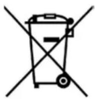
- The symbol with the crossed-out dustbin on the appliance or its packaging indicates that at the end of the product's life cycle, it must be collected separately from other waste.
- Suitable separate collection of the equipment for subsequent recycling, disposal contributes to preventing possible negative consequences for the environment and health, and favours the recycling of materials that the unit is made of.
- In accordance with European Directive 2012/19/EU, abusive disposal of the product by the user will result in application of penalties as set forth by local law.
treatment a
11. Guarantee
The warranty becomes void if:
The instructions in this manual are not complied with.
The scheduled maintenance and repairs are carried out by unauthorized personnel.
- The machine is used for any other than its intended purposes.
The original parts are replaced with parts from different manufacturers.
- The warranty does not cover damage caused by neglect, use and installation not in compliance with the recommendations of this manual, improper operation, abuse, lightning and atmospheric phenomena, overvoltage, overcurrent, or insufficient or irregular power supply.
12. Declaration of conformity (€
The manufacturer:
La San Marco S.p.A.

declares under its own responsibility that the ESPRESSO COFFEE MACHINE (as identified by the data on the tag located on the machine) is complaint with the following European directives: 2006/42/EC, 2014/35/EU, 2014/30/EU, Regulation (EC) no. 1935/2004, 2012/19/EU, 2011/65/EU.
For verification of compliance with said directives, the following harmonized standards have been applied: EN ISO 12100, EN 60335-1, EN 60335-2-75.
AUTHORISED PERSON A
COMPILE THE TECHNICAL FILE
Eng. Roberto Nocera
Gradisca d'Isonzo, December 2016
Ing. Roberto Nocera C.E.O.

13. Problem solving
| PROBLEM CAUSE | SOLUTION | ||
| 1. The boiler is full of water and the water flows out of the safety valve. The water level in the optical level is higher than the MAX. | ·The solenoid valve of the automatic filling always remains open. ·There is a fault in the manually valve for filling. | ·Close the main water valve and contact a qualified service technician authorized. ·The authorized qualified technician must check the correct operation of the filling solenoid valve, the electronics that control the automatic level and the eventual failure of the manually valve for filling. | |
| 2. Intervenes the safety valve by venting the steam. The gauge indicates the pressure of the boiler exceeding 1.8 bar. | ·Failure to the control system of resistance (electrical resistance is always powered). ·Failure of the safety thermostat. ·Increased pressure in the boiler (intervention of the safety valve 1.8bar) | ·Switch off the machine by putting the power switch to the 0 position and contact a qualified service technician authorized. ·The authorized qualified technician must check the electrical wiring that feeds the resistance, the temperature control system switch and safety thermostat. | |
| 3. The machine was started properly but the water in the boiler does not warm up. | ·The electric heating element is defective or is not connected. ·Main switch turned to position 1. | ·The main switch must be turned to position 2. ·The authorized qualified technician must check the electrical wiring that supplies the resistance. It also needs to check if the thermostat is tripped safety of the resistance and check for proper operation. | |
| 4. No dispensing water from a dispensing unit by lever group. | ·Coffee ground too fine or excessive quantity for type of filter used. ·The valve of the lever dispensing unit does not open because it is not properly adjusted. ·The water level is less than the MIN. ·Clogged water circuit. | ·Adjust the grinding coarseness and/or the quantity of ground coffee. ·The authorized qualified technician must check and verify that the valve of the unit is properly adjusted. ·Check that the water level is higher than the MAX. ·The authorized qualified technician must check and verify that the hydraulic circuit is not obstructed or there may be a pump failure. | |
| 5. No dispensing water from one of the electronic dispensing unit. | ·Coffee ground too fine or excessive quantity for type of filter used. ·The solenoid valve of a dispensing unit does not open because is broken. ·Clogged water circuit. | ·Adjust the grinding coarseness and/or the quantity of ground coffee. ·Check that the valves of volumetric meters are in “open” position. ·The authorized qualified technician must check and verify the volumetric meters and them valves. ·The authorized qualified technician must check the solenoid valve of the dispensing unit, its wiring and the fuse in the electronic control unit. ·The authorized qualified technician must check and verify that the hydraulic circuit is not obstructed or there may be a pump failure. | |
| PROBIEM CAUsE | sOIUTiOn | ||
| 6. The programmed servings of espresso coffee are not constant or vary on the different dispensing units. | ·Abnormal operation of the electronic control unit or of the flow meters. ·Leakage from solenoid valve of the dispensing unit. ·Water dispensers clogged. | ·Program the doses separately on each dispensing unit. ·The authorized qualified technician must check and if necessary replace the flow meter of the group. Check and if necessary replace the solenoid valve of the unit. Check the water dispensers. | |
| 7. It is not possible to program the dose quantities on unit 1 and to copy them on the other units. | ·Abnormal operation of the electronic control unit or of the flow meters. | ·The authorized qualified technician must check the electrical wiring between the control unit and flow meters and see if you need to replace the flow meters. | |
| 8. Flow meters alarm. · Flow meters blocked or failure. ·Electrical wiring defective. | ·The authorized qualified technician must check the electrical wiring between the control unit and flow meters and see if you need to replace the flow meters. | ||
| 9. Autolevel alarm. · Water circuit of automatic level without water. ·Main water supply valve closed. ·Faulty autolevel solenoid valve. | ·Check that the main water supply shut-off valve is open. ·The authorized qualified technician must check the automatic level hydraulic circuit and verify the correct operation solenoid valve and replace if necessary. | ||
| 10. The machine is switched on (the main switch is in position 1 or 2 and the signal light is lit) but the electronic control is out of order. | ·The electrical wiring of the electronic board or the touch panel is faulty. ·The electronic board or the touch panel is faulty. | ·The authorized qualified technician must check the electrical wiring of the electronic board and the touch panel. Check the operation of the the electronic board and the touch panel and if necessary replace the faulty components. | |
| 11. The machine is dispensing water from one dispensing unit although no coffee dose button has not been selected. | ·Dispensing unit solenoid valve and/or pump fed continuously. | ·The authorized qualified technician must check the electronic board and the touch panel. Check the operation of the the electronic board and the touch panel and if necessary replace the faulty components. | |
| 12. From the steam spout comes out a small amounts of water droplets even if in the closed position. | ·Gasket of the steam valve worn. ·The valve needs adjustment. | ·The authorized qualified technician must assess whether to replace the gasket if necessary or adjust the steam valve. | |
| 13. From the hot water spout comes out a small amounts of water droplets even if in the closed position. | ·Gasket of the hot water valve worn. ·The manually valve needs adjustment. | ·The authorized qualified technician must assess whether to replace the gasket if necessary or adjust the hot water manually valve. | |
| 14. The unit emits a whistle after dispensing of coffee. | ·Faulty operation of check valve. ·High pressure of the pump. | ·Verify the check valve and if necessary replace it. Calibrate the valve at 12 bar. ·The authorized qualified technician must check the pump operating pressure. Calibrate the pump at 9 bar. | |
| PROBIEM CAUsE sOIUTiOn | |||
| 15. | The filter cup comes off from the dispensing unit. | ·Worn gasket under the filter-cup. | ·Clean the dispensing unit and the filter-cup. ·The authorized qualified technician must check the gasket and replace if necessary. |
| 16. | When coffee is being dispensed, a part of it drips out of the edge of the filter-cup. | ·Worn gasket under the filter-cup. | ·Clean the dispensing unit and the filter-cup. ·The authorized qualified technician must check the gasket and replace if necessary. |
| 17. | Water leaking from the drain of dispensing unit solenoid valve. Only for electronic dispensing unit. | ·Malfunctioning of solenoid valve of electronic dispensing unit. | ·The authorized qualified technician must check if replace the unit solenoid valve. |
| 18. | Light cream (the coffee flows out of the spout fastly). | a) Coarse coffee grinding. b) Low pressing pressure. c) Small quantity of ground coffee. d) Water temperature too low. e) Pump pressure above 9 bar. f) Filter holes on dispensing unit are widened. g) Filter holes are widened (filter-cup). | a) Decrease coffee grinding. b) Increase the pressure of ground coffee. c) Increase the quantity of ground coffee. d) Increase the temperature of the dispensing unit. e) Decrease pump pressure (this operation can only be performed by authorized qualified technician). f) Check and clean the dispensing unit using cup with blind filter or replace filter. g) Check and replace filter of the filter-cup. |
| 19. | Dark cream (the coffee drips out of the spout too slowly). | a) Grinding coffee too fine. b) High pressing pressure. c) Large quantity of ground coffee. d) Water temperature too high. e) Pump pressure below 9 bar. f) Filter holes on dispensing unit are clogged. g) Filter holes are clogged (filter-cup). | a) Increase coffee grinding. b) Decrease the pressure of ground coffee. c) Decrease the quantity of ground coffee. d) Decrease the temperature of the dispensing unit. e) Increase pump pressure (this operation can only be performed by authorized qualified technician). f) Check and clean the dispensing unit using cup with blind filter or replace filter. g) Check and replace filter of the filter-cup. |
| 20. | Coffee grounds in the cup. a) | Grinding coffee too fine. b) Grinders of coffee grinder worn. c) Pump pressure above 9 bar. d) Filter holes on dispensing unit are clogged. e) Filter holes are clogged (filter-cup). | a) Increase coffee grinding. b) Replace grinders (this operation can only be performed by authorized qualified technician). c) Decrease pump pressure (this operation can only be performed by authorized qualified technician). d) Check and clean the dispensing unit using cup with blind filter or replace filter. e) Check and replace filter of the filter-cup. |
| PROBIEM CAUsE sOIUTiOn | ||
| 21. | Coffee with too little cream in cup (spurts out of spout). | Filter holes on dispensing unit are clogged. |
| 22. | The cream in the cup is too thin (it disappears after a few seconds). | Coffee extraction takes a long time due to clogged filter of dispensing unit. Coffee extraction takes a long time due to clogged filter of filter-cup. Water temperature too high. |
| 23. | Presence of depressions in the coffee grounds (looking inside the filter cup). | Filter of dispensing unit partly clogged. |
Note: If it is not possible to solve the problem as described above, or if other malfunctions develop, contact the authorized La San Marco service centre.
UTiLisaTiOn ET EnTrETiEn
MODEL DUaLE Class

Figure 1 Figure 2 Figure 4
32 36 36
2. Technical characteristics
- Index
- Introduction
- Using the manual
- 1.2Warnings
- Starting the coffee machine
- Technical characteristics
- Description of the machine
- Diagram of water feed system
- Legend
- Installation
- Equipment provided
- Water mains set-up
- FEEDING LINE
- DRAIN LINE
- Water softener (optional)
- Note:
- Installation of water system
- Installation of water system with motor pump (optional)
- Drain line
- Electrical connection
- start-up
- Charging the water in the boiler
- Heating the water in the boiler
- Adjustment of pump serving pressure
- Calibration of steam pressure in boiler
- Automatic operation - programming the coffee brewing cycles
- Alarms
- Operating instructions
- Dispensing espresso with LEVER unit.
- Dispensing coffee with electronic units.
- Drawing steam
- Drawing hot water
- Cup heater (optional)
- Routine maintenance
- Cleaning the serving units and the filter holder
- Cleaning the tray and the cup support grill
- Cleaning the steam spout
- Substitution of boiler water
- Idle periods
- Safety devices
- Manual reset safety thermostat
- Safety valve
- Information for users in the european community
- Guarantee
- Declaration of conformity (€
- Problem solving
- UTiLisaTiOn ET EnTrETiEn
- MODEL DUaLE Class
- 36 36
Brand : La San Marco
Model : Duale Class
Category : Coffee machine