JV102DSMJ - Electric saw MAKITA - Free user manual and instructions
Find the device manual for free JV102DSMJ MAKITA in PDF.
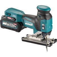
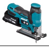
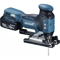
| Product Type | Cordless Jigsaw |
| Brand | Makita |
| Model | JV102DSMJ |
| Rated voltage | 10.8 V - 12 V DC max. |
| Stroke length | 23 mm |
| Strokes per minute | 800 to 3,000 min⁻¹ |
| Blade type | Type B |
| Max cutting capacity in wood | 90 mm |
| Overall length | 237 mm |
| Net weight | 1.8 to 1.9 kg |
| Cutting motion | Orbital (3 levels) and straight |
| Speed adjustment | 5 positions (1 to 5) |
| Sound pressure level (LpA) | 85 dB(A) |
| Sound power level (LWA) | 96 dB(A) |
| Vibration (cutting boards) | 11.5 m/s² |
| Vibration (cutting sheet metal) | 9.5 m/s² |
| Bevel cut | 0° to 45° (left/right) |
| Electronic functions | Soft start, progressive no-load speed, protections (overload, overheat, discharge) |
| Compatible batteries | BL1015, BL1016, BL1020B, BL1021B, BL1040B, BL1041B |
| Compatible chargers | DC10SA, DC10SB, DC10WC, DC10WD, DC18RE |
| Supplied accessories | Saw blade, hex wrench, parallel guide (depending on country) |
| Vacuum cleaner attachment | Yes (with dust nozzle) |
| Maintenance | Clean with a dry cloth, do not use solvents |
| Safety | Automatic stop in case of overload, overheating, or low battery |
Frequently Asked Questions - JV102DSMJ MAKITA
User questions about JV102DSMJ MAKITA
0 question about this device. Answer the ones you know or ask your own.
Ask a new question about this device
Download the instructions for your Electric saw in PDF format for free! Find your manual JV102DSMJ - MAKITA and take your electronic device back in hand. On this page are published all the documents necessary for the use of your device. JV102DSMJ by MAKITA.
USER MANUAL JV102DSMJ MAKITA
natural_image
Line drawing of a sewing machine tool with no visible text or symbols

text_image
Fig.1 1 2 3
text_image
1 Fig.5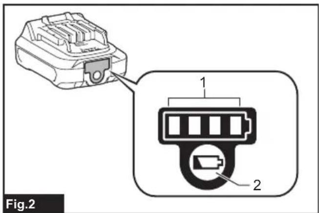
text_image
Fig.2 1 2
text_image
Fig.6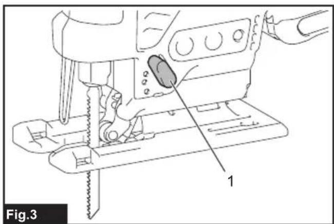
natural_image
Line drawing of a sewing machine needle and screwdriver (no text or symbols)
text_image
1 2 Fig.7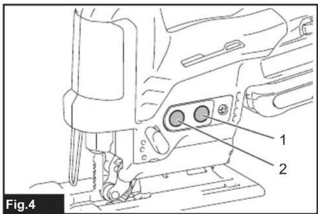
text_image
Fig.4 1 2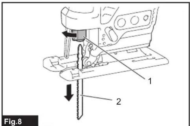
text_image
Fig.8 1 2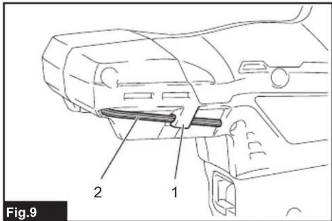
text_image
Fig.9 1 2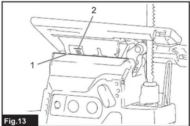
text_image
1 2 Fig.13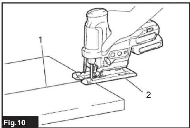
text_image
Fig.10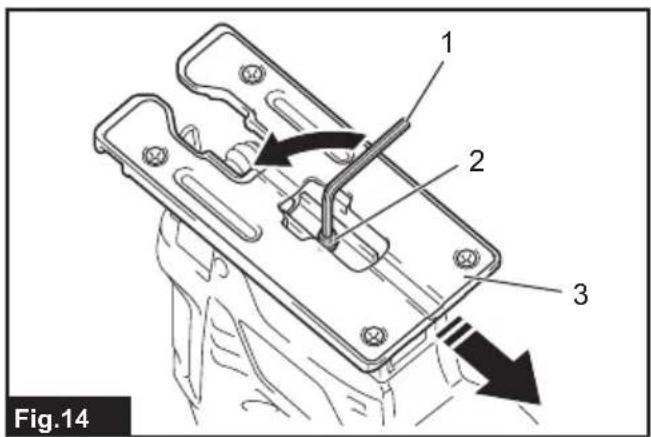
text_image
Fig.14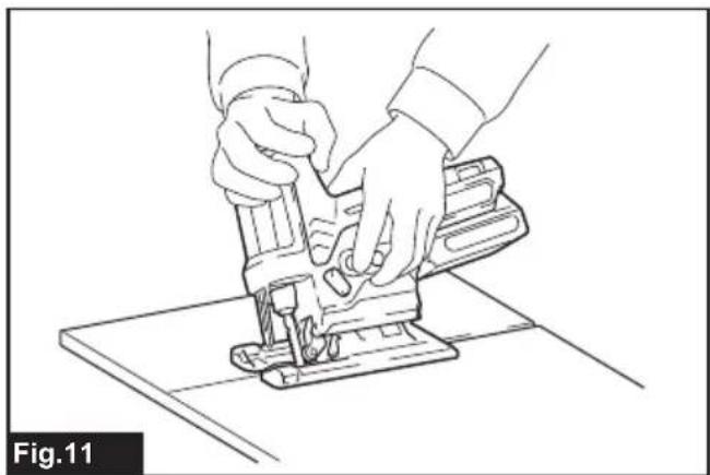
natural_image
Line drawing of hands operating a sewing machine on a flat base (no text or symbols)
natural_image
Line drawing of a sewing machine needle stitching flower-shaped cutouts on a base, with no text or symbols present.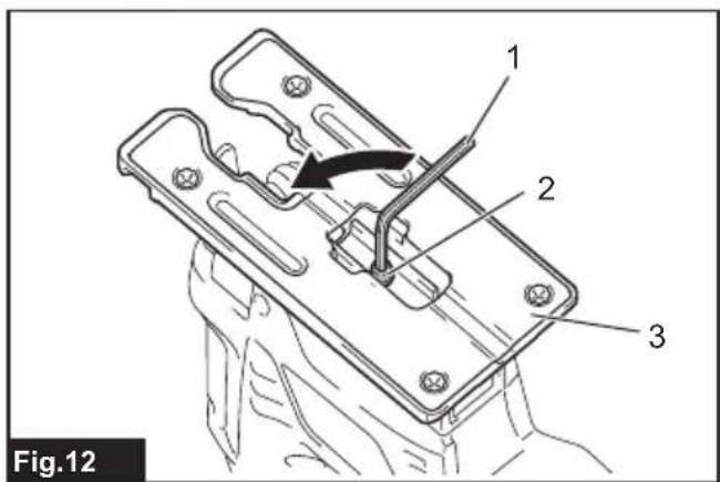
text_image
Fig.12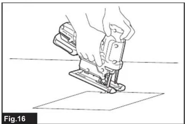
natural_image
Line drawing of a hand operating a sewing machine on a flat surface (no text or symbols)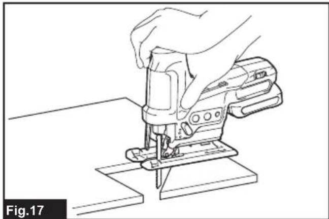
natural_image
Line drawing of a hand using a Schematic tool to cut or repair a piece of material (no text or symbols present)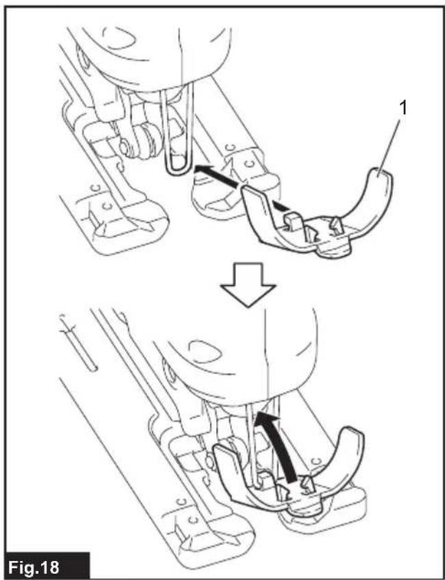
text_image
Fig.18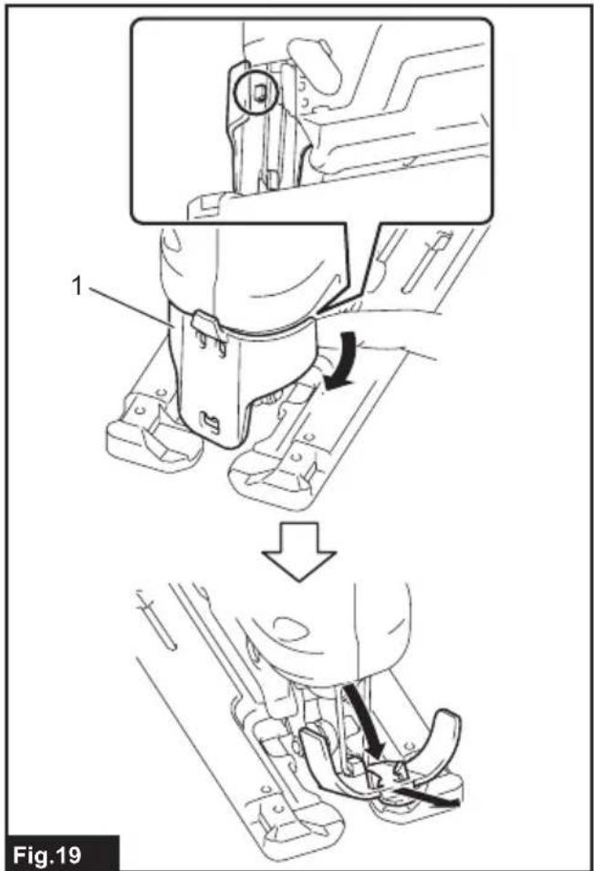
text_image
1 Fig.19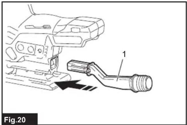
text_image
Fig.20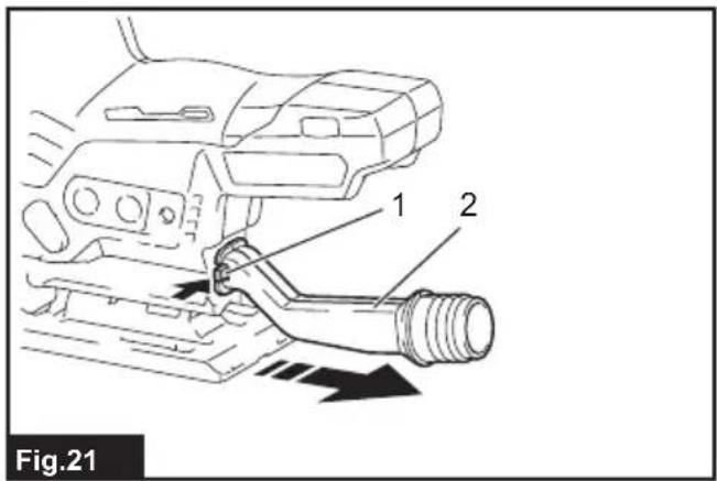
text_image
Fig.21 1 2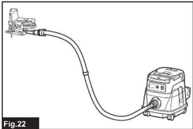
natural_image
Line drawing of a vacuum cleaner connected to a pump, labeled Fig.22 (no text or symbols on the diagram itself)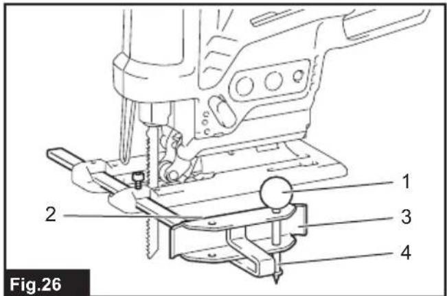
text_image
Fig.26 1 2 3 4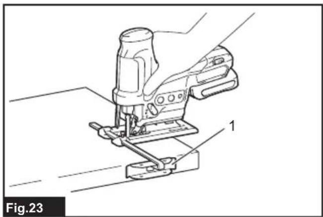
natural_image
Technical line drawing of a sewing machine with labeled parts (no text or symbols beyond label)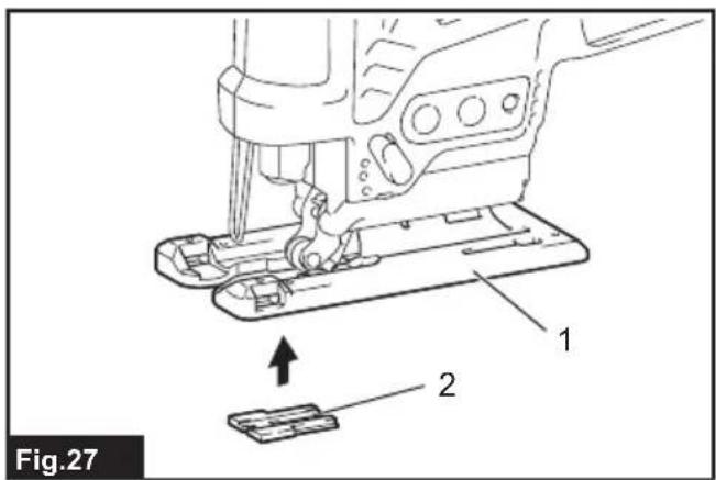
text_image
Fig.27 1 2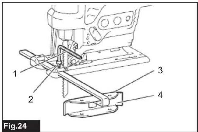
text_image
Fig.24
text_image
Fig.28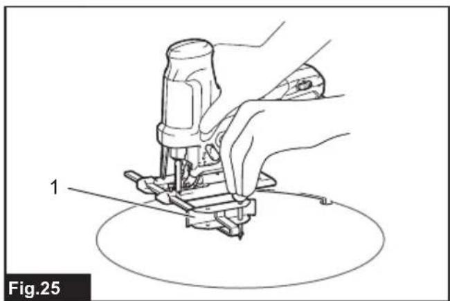
natural_image
Line drawing of a hand using a tool to press or install a component, labeled '1' and 'Fig.25' (no text or symbols on the diagram itself)
text_image
Fig.29 1 2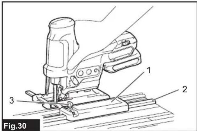
text_image
Fig.30 1 2 3SPECIFICATIONS
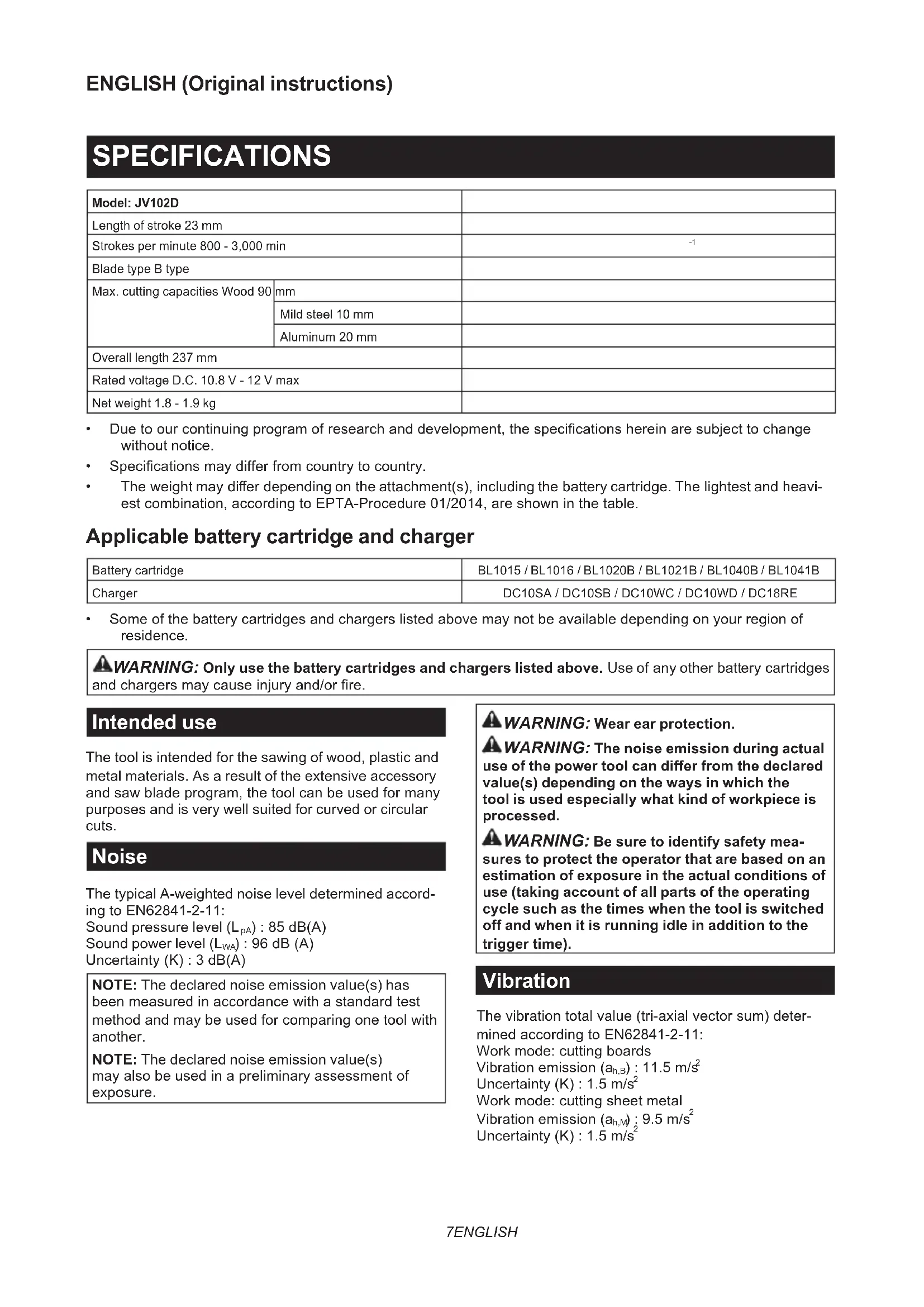
| Model: JV102D | ||
| Length of stroke 23 mm | ||
| Strokes per minute 800 - 3,000 min | -1 | |
| Blade type B type | ||
| Max. cutting capacities Wood 90 | mm | |
| Mild steel 10 mm | ||
| Aluminum 20 mm | ||
| Overall length 237 mm | ||
| Rated voltage D.C. 10.8 V - 12 V max | ||
| Net weight 1.8 - 1.9 kg | ||
- Due to our continuing program of research and development, the specifications herein are subject to change without notice.
• Specifications may differ from country to country. - The weight may differ depending on the attachment(s), including the battery cartridge. The lightest and heaviest combination, according to EPTA-Procedure 01/2014, are shown in the table.
Applicable battery cartridge and charger
| Battery cartridge | BL1015 / BL1016 / BL1020B / BL1021B / BL1040B / BL1041B |
| Charger | DC10SA / DC10SB / DC10WC / DC10WD / DC18RE |
- Some of the battery cartridges and chargers listed above may not be available depending on your region of residence.
⚠ WARNING: Only use the battery cartridges and chargers listed above. Use of any other battery cartridges and chargers may cause injury and/or fire.
Intended use
The tool is intended for the sawing of wood, plastic and metal materials. As a result of the extensive accessory and saw blade program, the tool can be used for many purposes and is very well suited for curved or circular cuts.
Noise
The typical A-weighted noise level determined according to EN62841-2-11:
Sound pressure level ( L_pA ): 85 dB(A)
Sound power level ( L_WA ): 96 dB (A)
Uncertainty (K) : 3 dB(A)
NOTE: The declared noise emission value(s) has been measured in accordance with a standard test method and may be used for comparing one tool with another.
NOTE: The declared noise emission value(s) may also be used in a preliminary assessment of exposure.
WARNING: Wear ear protection.
WARNING: The noise emission during actual use of the power tool can differ from the declared value(s) depending on the ways in which the tool is used especially what kind of workpiece is processed.
WARNING: Be sure to identify safety measures to protect the operator that are based on an estimation of exposure in the actual conditions of use (taking account of all parts of the operating cycle such as the times when the tool is switched off and when it is running idle in addition to the trigger time).
Vibration
The vibration total value (tri-axial vector sum) determined according to EN62841-2-11:
Work mode: cutting boards
Vibration emission (ah,B): 11.5 m/s²
Uncertainty (K) : 1.5 m/s ^4
Work mode: cutting sheet metal
Vibration emission (a_h,M) : 9.5m / s^2
Uncertainty (K) : 1.5 m/s²
NOTE: The declared vibration total value(s) has been measured in accordance with a standard test method and may be used for comparing one tool with another.
NOTE: The declared vibration total value(s) may also be used in a preliminary assessment of exposure.
WARNING: The vibration emission during actual use of the power tool can differ from the declared value(s) depending on the ways in which the tool is used especially what kind of workpiece is processed.
WARNING: Be sure to identify safety measures to protect the operator that are based on an estimation of exposure in the actual conditions of use (taking account of all parts of the operating cycle such as the times when the tool is switched off and when it is running idle in addition to the trigger time).
EC Declaration of Conformity
For European countries only
The EC declaration of conformity is included as Annex A to this instruction manual.
SAFETY WARNINGS
General power tool safety warnings
WARNING: Read all safety warnings, instructions, illustrations and specifications provided with this power tool. Failure to follow all instructions listed below may result in electric shock, fire and/or serious injury.
Save all warnings and instructions for future reference.
The term "power tool" in the warnings refers to your mains-operated (corded) power tool or battery-operated (cordless) power tool.
Cordless jig saw safety warnings
- Hold the power tool by insulated gripping surfaces, when performing an operation where the cutting accessory may contact hidden wiring. Cutting accessory contacting a "live" wire may make exposed metal parts of the power tool "live" and could give the operator an electric shock.
- Use clamps or another practical way to secure and support the workpiece to a stable platform. Holding the workpiece by hand or against your body leaves it unstable and may lead to loss of control.
- Always use safety glasses or goggles. Ordinary eye or sun glasses are NOT safety glasses.
- Avoid cutting nails. Inspect workpiece for any nails and remove them before operation.
-
Do not cut oversize workpiece.
-
Check for the proper clearance beyond the workpiece before cutting so that the blade will not strike the floor, workbench, etc.
- Hold the tool firmly.
- Make sure the blade is not contacting the workpiece before the switch is turned on.
- Keep hands away from moving parts.
- Do not leave the tool running. Operate the tool only when hand-held.
- Always switch off and wait for the blade to come to a complete stop before removing the blade from the workpiece.
- Do not touch the blade or the workpiece immediately after operation; they may be extremely hot and could burn your skin.
- Do not operate the tool at no-load unnecessarily.
- Some material contains chemicals which may be toxic. Take caution to prevent dust inhalation and skin contact. Follow material supplier safety data.
- Always use the correct dust mask/respirator for the material and application you are working with.
SAVE THESE INSTRUCTIONS.
WARNING: DO NOT let comfort or familiarity with product (gained from repeated use) replace strict adherence to safety rules for the subject product. MISUSE or failure to follow the safety rules stated in this instruction manual may cause serious personal injury.
Important safety instructions for battery cartridge
- Before using battery cartridge, read all instructions and cautionary markings on (1) battery charger, (2) battery, and (3) product using battery.
- Do not disassemble battery cartridge.
- If operating time has become excessively shorter, stop operating immediately. It may result in a risk of overheating, possible burns and even an explosion.
- If electrolyte gets into your eyes, rinse them out with clear water and seek medical attention right away. It may result in loss of your eyesight.
- Do not short the battery cartridge:
(1) Do not touch the terminals with any conductive material.
(2) Avoid storing battery cartridge in a container with other metal objects such as nails, coins, etc.
(3) Do not expose battery cartridge to water or rain.
A battery short can cause a large current flow, overheating, possible burns and even a breakdown.
-
Do not store the tool and battery cartridge in locations where the temperature may reach or exceed 50 °C (122 °F).
-
Do not incinerate the battery cartridge even if it is severely damaged or is completely worn out. The battery cartridge can explode in a fire.
- Be careful not to drop or strike battery.
- Do not use a damaged battery.
- The contained lithium-ion batteries are subject to the Dangerous Goods Legislation requirements.
For commercial transports e.g. by third parties, forwarding agents, special requirement on packaging and labeling must be observed.
For preparation of the item being shipped, consulting an expert for hazardous material is required.
Please also observe possibly more detailed national regulations.
Tape or mask off open contacts and pack up the battery in such a manner that it cannot move around in the packaging.
- Follow your local regulations relating to disposal of battery.
- Use the batteries only with the products specified by Makita. Installing the batteries to non-compliant products may result in a fire, excessive heat, explosion, or leak of electrolyte.
SAVE THESE INSTRUCTIONS.
⚠️CAUTION: Only use genuine Makita batteries. Use of non-genuine Makita batteries, or batteries that have been altered, may result in the battery bursting causing fires, personal injury and damage. It will also void the Makita warranty for the Makita tool and charger.
Tips for maintaining maximum battery life
- Charge the battery cartridge before completely discharged. Always stop tool operation and charge the battery cartridge when you notice less tool power.
- Never recharge a fully charged battery cartridge. Overcharging shortens the battery service life.
- Charge the battery cartridge with room temperature at 10 °C - 40 °C ( 50 °F - 104 °F ). Let a hot battery cartridge cool down before charging it.
FUNCTIONAL DESCRIPTION
CAUTION: Always be sure that the tool is switched off and the battery cartridge is removed before adjusting or checking function on the tool.
Installing or removing battery cartridge
⚠️ CAUTION: Always switch off the tool before installing or removing of the battery cartridge.
⚠️ CAUTION: Hold the tool and the battery cartridge firmly when installing or removing battery cartridge. Failure to hold the tool and the battery cartridge firmly may cause them to slip off your hands and result in damage to the tool and battery cartridge and a personal injury.
▶ Fig.1: 1. Red indicator 2. Button 3. Battery cartridge
To remove the battery cartridge, slide it from the tool while sliding the button on the front of the cartridge.
To install the battery cartridge, align the tongue on the battery cartridge with the groove in the housing and slip it into place. Insert it all the way until it locks in place with a little click. If you can see the red indicator on the upper side of the button, it is not locked completely.
⚠️ CAUTION: Always install the battery cartridge fully until the red indicator cannot be seen. If not, it may accidentally fall out of the tool, causing injury to you or someone around you.
⚠️ CAUTION: Do not install the battery cartridge forcibly. If the cartridge does not slide in easily, it is not being inserted correctly.
Tool / battery protection system
The tool is equipped with a tool/battery protection system. This system automatically cuts off power to the motor to extend tool and battery life. The tool will automatically stop during operation if the tool or battery is placed under one of the following conditions:
Overload protection
When the battery is operated in a manner that causes it to draw an abnormally high current, the tool automatically stops without any indication. In this situation, turn the tool off and stop the application that caused the tool to become overloaded. Then turn the tool on to restart.
Overheat protection
When the tool or battery is overheated, the tool stops automatically and the lamp blinks. In this case, let the tool and battery cool before turning the tool on again.
Overdischarge protection
When the battery capacity is not enough, the tool stops automatically. If you turn the tool on, the motor runs again but stops soon. In this case, remove the battery from the tool and charge the battery.
Indicating the remaining battery capacity
Only for battery cartridges with the indicator
▶ Fig.2: 1. Indicator lamps 2. Check button
Press the check button on the battery cartridge to indicate the remaining battery capacity. The indicator lamps light up for a few seconds.
| Indicator lamps Remaining | capacity | |
| Lighted Off | ||
| 75% to 100% | ||
| 50% to 75% | ||
| 25% to 50% | ||
| 0% to 25% | ||
NOTE: Depending on the conditions of use and the ambient temperature, the indication may differ slightly from the actual capacity.
Selecting the cutting action
▶ Fig.3: 1. Cutting action changing lever
This tool can be operated with an orbital or a straight line (up and down) cutting action. The orbital cutting action thrusts the jig saw blade forward on the cutting stroke and greatly increases cutting speed.
To change the cutting action, just turn the cutting action changing lever to the desired cutting action position. Refer to the table to select the appropriate cutting action.
| Position Cutting action Applications | ||
| 0 Straight line cuttingaction | For cutting mildsteel, stainlesssteel and plastics. | |
| For clean cuts inwood and plywood. | ||
| I Small orbit cuttingaction | For cutting mildsteel, aluminumand hard wood. | |
| II Medium orbitcutting action | For cutting woodand plywood. | |
| For fast cutting inaluminum and mildsteel. | ||
| III Large orbit cuttingaction | For fast cutting inwood and plywood. | |
Switch action
To turn on the tool, press the lock/unlock button. The tool turns into the standby mode. To start the tool, press the start/stop button in the standby mode. To stop the tool, press the start/stop button again. The tool turns into the standby mode. To turn off the tool, press the lock/unlock button in the standby mode.
▶ Fig.4: 1. Lock/unlock button 2. Start/stop button
NOTE: If the tool is left for 10 seconds without any operation in the standby mode, the tool automatically turns off and the lamp goes off.
NOTE: You can also stop and turn off the tool by pressing the lock/unlock button while the tool is operating.
Lighting up the front lamp
CAUTION: Do not look in the light or see the source of light directly.
To turn on the lamp, press the lock/unlock button. To turn off the lamp, press the lock/unlock button again.
NOTICE: When the tool is overheated, the lamp flickers. Cool down the tool fully before operating the tool again.
NOTE: Use a dry cloth to wipe the dirt off the lens of the lamp. Be careful not to scratch the lens of lamp, or it may lower the illumination.
Speed adjusting dial
▶ Fig.5: 1. Speed adjusting dial
The tool speed can be adjusted by turning the speed adjusting dial. You can get the highest speed at 5 and the lowest speed at 1.
Refer to the table to select the proper speed for the workpiece to be cut. However, the appropriate speed may differ with the type or thickness of the workpiece. In general, higher speeds will allow you to cut workpieces faster but the service life of the blade will be reduced.
| Workpiece Number | |
| Wood 4 - 5 | |
| Mild steel 3 - 5 | |
| Stainless steel | 3 - 4 |
| Aluminum | 3 - 5 |
| Plastics | 1 - 4 |
NOTICE: When changing the speed dial from "5" to "1", turn the dial counterclockwise. Do not turn the dial clockwise forcibly.
Electronic function
The tool is equipped with the electronic functions for easy operation.
- Soft start The soft-start function minimizes start-up shock, and makes the tool start smoothly.
- Soft no-load rotation To reduce the vibration and align the jig saw blade with the cutting line easily, the tool automatically reduces the rotation speed until the tool starts cutting the workpiece when the speed adjusting dial is set at 2 or higher. Once the tool starts cutting the workpiece, the tool speed reaches the preset speed and keeps the speed until the tool stops.
NOTE: When the temperature is low, this function may not be available.
Disabling the soft no-load rotation function
To disable the soft no-load rotation function, follow the steps below.
- Make sure that the tool is turned off.
- Set the speed adjusting dial to "1".
- Press the lock/unlock button to turn on the tool.
- Set the speed adjusting dial to "5" by turning it, and then set it to "1" by turn it back.
The lamp blinks twice to indicate that the soft no-load rotation function is disabled. To enable this function again, perform the same procedure again.
NOTE: If the soft no-load rotation function is disabled, the lamp blinks twice when the tool is turned on.
NOTE: You can also disable or enable the soft no-load rotation function by changing the speed adjusting dial from "5" to "1" and changing it from "1" to "5".
ASSEMBLY
⚠️CAUTION: Always be sure that the tool is switched off and the battery cartridge is removed before carrying out any work on the tool.
Installing or removing jig saw blade
⚠️CAUTION: Always clean out all chips or foreign matter adhering to the jig saw blade and/or blade holder. Failure to do so may cause insufficient tightening of the blade, resulting in a serious personal injury.
⚠️CAUTION: Do not touch the jig saw blade or the workpiece immediately after operation. They may be extremely hot and could burn your skin.
⚠️CAUTION: Always secure the jig saw blade firmly. Insufficient tightening of the blade may cause blade breakage or serious personal injury.
⚠️CAUTION: Use only B type jig saw blades. Using blades other than B type causes insufficient tightening of the blade, resulting in a serious personal injury.
⚠CAUTION: When you remove the jig saw blade, be careful not to hurt your fingers with the top of the blade or the tips of workpiece.
Before installing the jig saw blade, make sure that the blade clamp lever is in the released position.
To install the jig saw blade, insert the blade (teeth facing forward) into the blade holder. The lever moves to the fixed position and the blade is locked. Make sure that the back edge of the blade fits into the roller. Pull the blade lightly to make sure that the blade does not fall off during operation.
▶ Fig.6: 1. Jig saw blade holder 2. Released position 3. Fixed position
▶ Fig.7: 1. Jig saw blade holder 2. Jig saw blade
⚠️ CAUTION: If the lever does not move to the fixed position, the blade is not installed completely. Do not press the lever by hand to the fixed position. It may damage the tool.
To remove the jig saw blade, push the lever forward as far as it will go. This allows the blade to be released.
▶ Fig.8: 1. Jig saw blade holder 2. Jig saw blade
NOTE: Occasionally lubricate the roller.
Hex wrench storage
▶ Fig.9: 1. Hook 2. Hex wrench
When not in use, store the hex wrench as shown in the figure to keep it from being lost.
First, insert the hex wrench into the hole. Then push it into the hook until it locked.
OPERATION
CAUTION: Always hold the base flush with the workpiece. Failure to do so may cause jig saw blade breakage, resulting in a serious injury.
CAUTION: Advance the tool very slowly when cutting curves or scrolling. Forcing the tool may cause a slanted cutting surface and jig saw blade breakage.
▶ Fig.10: 1. Cutting line 2. Base
Turn the tool on without the jig saw blade making any contact and wait until the blade attains full speed. Then rest the base flat on the workpiece and gently move the tool forward along the previously marked cutting line.
Bevel cutting
CAUTION: Always be sure that the tool is switched off and the battery cartridge is removed before tilting the base.
With the base tilted, you can make bevel cuts at any angle between 0^ and 45^ (left or right).
▶ Fig.11
Loosen the bolt on the back of the base with the hex wrench. Move the base so that the bolt is positioned in the center of the cross-shaped slot in the base.
▶ Fig.12: 1. Hex wrench 2. Bolt 3. Base
Tilt the base until the desired bevel angle is obtained. The edge of the motor housing indicates the bevel angle by graduations. Then tighten the bolt to secure the base.
▶ Fig.13: 1. Edge 2. Graduation
Front flush cuts
▶ Fig.14: 1. Hex wrench 2. Bolt 3. Base
Loosen the bolt on the back of the base with the hex wrench and slide the base all the way back. Then tighten the bolt to secure the base.
Cutouts
Cutouts can be made with either of two methods "Boring a starting hole" or "Plunge cutting".
Boring a starting hole
▶ Fig.15
For internal cutouts without a lead-in cut from an edge, pre-drill a starting hole 12 mm or more in diameter. Insert the jig saw blade into this hole to start your cut.
Plunge cutting
▶ Fig.16
You need not bore a starting hole or make a lead-in cut if you carefully do as follows.
- Tilt the tool up on the front edge of the base with the jig saw blade point positioned just above the workpiece surface.
- Apply pressure to the tool so that the front edge of the base will not move when you switch on the tool and gently lower the back end of the tool slowly.
- As the jig saw blade pierces the workpiece, slowly lower the base of the tool down onto the workpiece surface.
- Complete the cut in the normal manner.
Finishing edges
▶ Fig.17
To trim edges or make dimensional adjustments, run the jig saw blade lightly along the cut edges.
Metal cutting
Always use a suitable coolant (cutting oil) when cutting metal. Failure to do so will cause significant jig saw blade wear. The underside of the workpiece can be greased instead of using a coolant.
Dust extraction
Optional accessory
Clean cutting operations can be performed by connecting this tool to a Makita vacuum cleaner.
Installing or removing the dust cover
Install the dust cover as shown in the figure.
▶ Fig.18: 1. Dust cover
To remove the dust cover, press one side of the cover, and then remove it as shown in the figure.
▶ Fig.19: 1. Dust cover
Installing or removing the dust nozzle
Insert the dust nozzle all the way into the tool.
▶ Fig.20: 1. Dust nozzle
To remove the dust nozzle, pull out the dust nozzle while pressing the button on the dust nozzle.
▶ Fig.21: 1. Button 2. Dust nozzle
Connecting the tool to the vacuum cleaner
Connect the hose of the vacuum cleaner to the dust nozzle.
▶ Fig.22
Rip fence
Optional accessory
CAUTION: Always be sure that the tool is switched off and the battery cartridge is removed before installing or removing accessories.
Straight cuts
When repeatedly cutting widths of 160 mm or less, use of the rip fence will assure fast, clean, straight cuts.
▶ Fig.23: 1. Rip fence (Guide rule)
To install, insert the rip fence into the rectangular hole on the side of the base with the fence guide facing down. Slide the rip fence to the desired cutting width position, then tighten the bolt to secure it.
▶ Fig.24: 1. Hex wrench 2. Bolt 3. Fence guide 4. Rip fence (Guide rule)
Circular cuts
When cutting circles or arcs of 170 mm or less in radius, install the rip fence as follows.
▶ Fig.25: 1. Rip fence (Guide rule)
- Insert the rip fence into the rectangular hole on the side of the base with the fence guide facing up.
- Insert the circular guide pin through either of the two holes on the fence guide. Screw the threaded knob onto the pin to secure the pin.
▶ Fig.26: 1. Threaded knob 2. Fence guide 3. Rip fence (Guide rule) 4. Pin - Slide the rip fence to the desired cutting radius, and tighten the bolt to secure it in place. Then move the base all the way forward.
NOTE: Always use jig saw blades No. B-17, B-18, B-26 or B-27 when cutting circles or arcs.
Anti-splintering device
Optional accessory
CAUTION: The anti-splintering device cannot be used when making bevel cuts.
▶ Fig.27: 1. Base 2. Anti-splintering device
For splinter-free cuts, the anti-splintering device can be used. To install the anti-splintering device, move the tool base all the way forward and fit it from the back of tool base.
When you use the cover plate, install the anti-splintering device onto the cover plate.
Cover plate
Optional accessory
▶ Fig.28: 1. Cover plate 2. Base
Use the cover plate when cutting decorative veneers, plastics, etc. It protects sensitive or delicate surfaces from damage. Fit it on the back of the tool base.
Guide rail adapter set
Optional accessory
When cutting parallel and uniform width or cutting straight, the use of the guide rail and the guide rail adapter will assure the production of fast and clean cuts. To install the guide rail adapter, insert the rule bar into the square hole of the base as far as it goes. Secure the bolt with the hex wrench securely.
▶ Fig.29: 1. Hex wrench 2. Rule bar
Insert the rule bar into the square hole of the guide rail adapter, and secure the screw firmly. Place the guide rail adapter on the guide rail.
▶ Fig.30: 1. Guide rail adapter 2. Guide rail 3. Screw
NOTICE: Always use blades No. B-8, B-13, B-16, B-17 or 58 when using the guide rail and the guide rail adapter.
MAINTENANCE
CAUTION: Always be sure that the tool is switched off and the battery cartridge is removed before attempting to perform inspection or maintenance.
NOTICE: Never use gasoline, benzine, thinner, alcohol or the like. Discoloration, deformation or cracks may result.
To maintain product SAFETY and RELIABILITY, repairs, any other maintenance or adjustment should be performed by Makita Authorized or Factory Service Centers, always using Makita replacement parts.
OPTIONAL ACCESSORIES
⚠️CAUTION: These accessories or attachments are recommended for use with your Makita tool specified in this manual. The use of any other accessories or attachments might present a risk of injury to persons. Only use accessory or attachment for its stated purpose.
If you need any assistance for more details regarding these accessories, ask your local Makita Service Center.
- Jig saw blades
- Hex wrench 3
- Rip fence (guide rule) set
- Guide rail adapter set
• Anti-splintering device - Hose (For vacuum cleaner)
- Cover plate
- Dust nozzle
- Dust cover
• Makita genuine battery and charger
NOTE: Some items in the list may be included in the tool package as standard accessories. They may differ from country to country.
SPÉCIFICATIONS
▶ Fig.13: 1. Bord 2. Graduation
Coupes à ras avant
▶ Fig.14: 1. Clé hexagonale 2. Boulon 3. Base
▶ Fig.18: 1. Pare-poussière
▶ Fig.28: 1. Semelle 2. Base
▶ Abb.9: 1. Haken 2. Inbusschlüssel
⚠ WAARSCHUWING: Draag gehoorbescherming.
VEILIGHEIDSWAAR- SCHUWINGEN
OPTIONELE ACCESSOIRES
▶ Fig.9: 1. Gancho 2. Llave hexagonal
▶ Fig.12: 1. Llave hexagonal 2. Perno 3. Base
▶ Fig.14: 1. Llave hexagonal 2. Perno 3. Base
▶ Fig.29: 1. Llave hexagonal 2. Regla
3-11-8, Sumiyoshi-cho,
Anjo, Aichi 446-8502 Japan