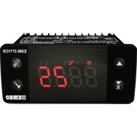
ESM3711HN - Temperature Controller Emko - Free user manual and instructions
Find the device manual for free ESM3711HN Emko in PDF.

User questions about ESM3711HN Emko
0 question about this device. Answer the ones you know or ask your own.
Ask a new question about this device
Download the instructions for your Temperature Controller in PDF format for free! Find your manual ESM3711HN - Emko and take your electronic device back in hand. On this page are published all the documents necessary for the use of your device. ESM3711HN by Emko.
USER MANUAL ESM3711HN Emko
- Temperature control with manual heating function - Alarm parameters - Adjustable internal buzzer according to cooking time, sensor defect and Alarm status. - Password protection for programming section - Installing parameters using Prokey - Remote access, data collecting and controlling with Modbus RTU - Having CE mark according to European Norms J Type thermocouple Input or, K Type thermocouple Input or, 2-Wire PT-100 Input or, 2-Wire PT-1000 Input ON/OFF temperature control - Adjustable temperature offset - Set value low limit and set value high limit boundaries - Relay or SSR driver output - Digital Input (Cooking Time Start/Stop Input) - Adjustable cooking time from front panel - Temperature control according to the cooking time (Timer) - User can select to start cooking time (Timer) when temperature reaches to the set value - Button protection ESM-3711HN 77 x 35 DIN Size Digital , ON / OFF Temperature ControllerOperating Temperature : -30 to 80 °C Max. Operating Humidity : 90% Rh (non-condensing) Altitude : Up to 2000 m. Forbidden Conditions: Corrosive atmosphere Explosive atmosphere Home applications (The unit is only for industrial applications)
1.2 General Specifications
1.Preface ESM-3711HN series heating controllers are designed for measuring and controlling temperature. They can be used in many applications with their easy use, On/ Off control form and cooking time properties. Some application fields which they are used are below: Application Fields Applications Glass Heating Food Baking Ovens Plastic Incubators Petro-Chemistry Storages Textile, Automative Air Conditioning Machine Production Industries Etc... Etc...
1.1 Environmental Ratings
A visual inspection of this product for possible damage occurred during shipment is recommended before installation. It is your responsibility to ensure that qualified mechanical and electrical technicians install this product. If there is danger of serious accident resulting from a failure or defect in this unit, power off the system and separate the electrical connection of the device from the system. The unit is normally supplied without a power supply switch or a fuse. Use power switch and fuse as required. Be sure to use the rated power supply voltage to protect the unit against damage and to prevent failure. Keep the power off until all of the wiring is completed so that electric shock and trouble with the unit can be prevented. Never attempt to disassemble, modify or repair this unit. Tampering with the unit may results in malfunction, electric shock or fire. Do not use the unit in combustible or explosive gaseous atmospheres. During putting equipment in hole on the metal panel while mechanical installation some metal burrs can cause injury on hands, you must be careful. Montage of the product on a system must be done with it’s fixing clamps. Do not do the montage of the device with inappropriate fixing clamp. Be sure that device will not fall while doing the montage. It is your responsibility if this equipment is used in a manner not specified in this instruction manual. EMKO Elektronik warrants that the equipment delivered is free from defects in material and workmanship. This warranty is provided for a period of two years. The warranty period starts from the delivery date. This warranty is in force if duty and responsibilities which are determined in warranty document and instruction manual performs by the customer completely. Repairs should only be performed by trained and specialized personnel. Cut power to the device before accessing internal parts. Do not clean the case with hydrocarbon-based solvents (Petrol, Trichlorethylene etc.). Use of these solvents can reduce the mechanical reliability of the device. Use a cloth dampened in ethyl alcohol or water to clean the external plastic case.
1.6 Manufacturer Company
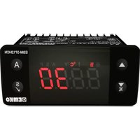
2.1 Front View and Dimensions of ESM-3711HN Temperature Controller
Mounting Clamp Panel Surface (maximum thickness 15 mm / 0.59 inch) Front Panel IP65 protection
ENGLISH5 1.Switch off the device.2.Put in PROKEY then energize the device.3.When the device is energized, the parameter values in PROKEY, start downloading to the device automatically. At first, message is shown on the display, when loading has finished, message is shown.4.After 10 seconds device starts to operate with new parameter values.5.Remove the PROKEY. 1-Before mounting the device in your panel, make sure that the cut-out is of the right size.2-Insert the device through the cut-out. If the mounting clamps are on the unit, put out them before inserting the unit to the panel.3- Insert the mounting clamps to the fixing sockets that located left and right sides of device and make the unit completely immobile within the panel1-Pull mounting clamps from left and right fixing sockets.2-Pull the unit through the front side of the panelBefore starting to remove the unit from panel, power off the unit and the related system.
2.4 Removing from the Panel
DOWNLOADING FROM DEVICE TO PROKEY1.The device is programmed by using the parameters.2.Energize the device then put in PROKEY and press button. Message is shown on the display. When the loading has finished, message is shown.3.Press any button to turn back to main operation screen.4.Remove the PROKEY.DOWNLOADING FROM PROKEY TO DEVICE NOTE: message is shown when an error occurs while programming. If you want to reload, put in PROKEY and press button. If you want to quit, remove PROKEY and press button. The device will turn back to main operation screen.NOTE: message is shown when an error occurs while programming. If you want to reload, switch off the device and put in PROKEY then energize the device. If you want to quit remove PROKEY and press button. The device will turn back to main operation screen.TO USE PROKEY, VALUE OF THE PrC PARAMETER MUST BE ‘0’.IF PrC=1 AND BUTTON IS PRESSED MESSAGE WILL BE SHOWN. 10s. LATER DEVICE TURNS BACK TO THE MAIN OPERATION SCREEN OR YOU CAN PRESS SET BUTTON TO TURN BACK TO MAIN OPERATION SCREEN.
ENGLISH4.2 Device Label and Connection Diagram
4. Electrical Wiring Diagram
4.1 Supply Voltage Input Connection of the Device
Make sure that the power supply voltage is the same indicated on the instrument.Switch on the power supply only after that all the electrical connections have been completed.Supply voltage range must be determined in order. While installing the unit, supply voltage range must be controlled and appropriate supply voltage must be applied to the unit. There is no power supply switch on the device. So a power supply switch must be added to the supply voltage input.Power switch must be two poled for seperating phase and neutral, On/Off condition of power supply switch is very important in electrical connection. External fuse that on Vpower supply inputs must be on phase connection.External fuse that on Zpower supply inputs must be on (+) connection.
230VV CONNECTION DIAGRAM
Power Supply Connection
EXTERNAL FUSE (1A T)Note-1SupplySwitchSupply Voltage
** It is used to increase the value in the Set screen and Programming mode.
2. Decrement, Silencing Buzzer and Downloading to Prokey Button :
** It is used to decrease the value in the Set screen and Programming mode. ** It is used to silence the buzzer. ** If Prc = 0, it is used to download from device to prokey.
** In the main operation screen; if this button pressed, set value will be displayed. Value can be changed using increment and decrement buttons. When Enter button pressed, value is saved and returns back to main operating screen. ** To access the programming screen; in the main operation screen, press this button for 5 seconds. ** It is used to saving value in the Set screen and programming screen.
** In the main operation screen; if this button pressed, cooking time value will be displayed. **In the main operation screen; if this button pressed for 3 seconds, cooking time starts. LED DEFINITIONS ** This led indicates that cooking time is active. ** Blinks (5 Hz) while entering Cooking time value. 7.Alarm led : ** It is active when low alarm and high alarm statuses. 8.Celcius led :
** Indicates that device is in C mode. 9.Fahrenheit led :
** Indicates that device is in F mode. 10.Set led : ** Indicates that device is in Set value changing mode. 11.Program led : **Blinks in programming mode .
5. Cooking Time led :
** This led indicates that heating control is selected and process output relay is active.
ENGLISH6. Changing and Saving Temperature Set Value Main Operation ScreenWhen SET button pressed ‘’S’’ led will be active and temperature set value will be displayed.SET Value ScreenTemperature set value can be changed with increment and decrement buttons.When ENTER button pressed temperature set value can be saved.‘’S’’ will be inactive and goes back to main operation screen.Main Operation ScreenTemperature set value parameter (Default = 10) MODBUS ADDRESS:40001Temperature set value, can be programmed between minimum temperature set value and maximum temperature set value . SET Value Screen
6.1 Changing and Saving Cookıng Time (Timer) Parameter Value
When defrost button is pressed, cooking time is shown and cooking time led starts to fast blink (5 Hz).Press set button for saving the cooking time Cooking time is saved, cooking time led active led lights off, main operation screen is shown.Main Operating ScreenCooking Time (Timer) Value ScreenIf no operation is performed in defrost time set value changing mode and temperature set value changing mode for 20 seconds, device turns to main operation screen automatically. Change the cooking time with increment and decrement buttons.Main Operating ScreenCooking Time (Timer) Value Screen
Hysteresis Parameter for Compressor Output ( Default = 1 ) MODBUS ADDRESS:40004 from 1 to 20°C for NTC (-50°C, 100°C) or PTC (-50°C, 150°C) or J Type TC ( 0°C, 800°C ) or K Type TC ( 0°C, 1000°C or PT-100 Type ( -50°C,400°C ) or PT-1000 Type ( -50°C,400°C ) or PT-100 Type ( -20°C,100°C ), from 1 to 36°F for NTC (-58°F, 212°F) or PTC (-58°F, 302°F) or J Type TC (32°F,1472°F)or K Type TC (32°F,1830°F) or PT-100 Type (-58°F,752°F) or PT-1000 Type (-58°F,752°F) or PT-100 Type (-4°F,212°F) from 0.1 to 10.0°C for NTC(-50.0°C,100.0°C) or PTC (-50.0°C,150.0°C) or PT-100 (-19.9°C,99.9°C), from 0.1 to 18.0°F for NTC (-58.0°F,212.0°F) or PTC (-58.0°F,302.0°F) or PT-100 (-4.0°F,212.0°F), In ON/OFF control algorithm, temperature value is tried to keep equal to set value by opening or closing the last control element. ON/OFF controlled system, temperature value oscillates continuously. Temperature value’s oscillation period or amplitude around set value changes according to controlled system. For reducing oscillation period of temperature value, a threshold zone is formed below or around set value and this zone is named hysteresis.
OFF TemperatureControlOutput Set HSt Time HSt Time Minimum Temperature Set Value Parameter (Default = Minimum Value of Device Scale ) MODBUS ADDRESS:40005 Temperature set value can not be lower than this value. This parameter value can be adjusted from minimum value of device scale to maximum temperature set value parameter Maximum Temperature Set Value Parameter (Default = Maximum Value of Device Scale ) MODBUS ADDRESS:40006 Temperature set value can not be bigger than this value. This parameter value can be adjusted from minimum temperature set value parameter to maximum value of the device scale Decimal Seperator Enabling Parameter ( Default = 0 ) MODBUS ADDRESS:40003 Disable. Enable. Temperature Unit Selection Parameter ( Default = 0 ) MODBUS ADDRESS:40002 °C selected. °F selected. Note: If sensor input type is selected J, K, PT-100 or PT-1000 (BC = 05,10,11 or 14) parameter becomes passive and can not be changed. Temperature Control Delay at Power On It can be adjusted from 0 to 99 minutes. ( Default = 0 ) MODBUS ADRES : 40008 ENGLISH10 Cooking Time (Timer) Parameter It can be adjusted from 1 to 999 minutes. When it is 1, can be observed by pressing decrement button on the display. So Manual Control is selected. In Manual control, user can start and stop temperature controlling with cooking ON/OFF button or
( Default = 45 ) MODBUS ADDRESS : 40009 cooking time start/stop input Selection of Temperature Control and Starting Cooking Time (Timer) Parameter (Default = 0 ) MODBUS ADDRESS : 40010 Temperature control and cooking time (Timer) starts at power on. Temperature control starts at power on. Cooking time (Timer) can be started by pressing cooking ON/OFF button or when cooking time start/stop input is getting closed condition. Temperature control and cooking time (Timer) can be started by pressing cooking ON/OFF button or when cooking time start/stop input is getting closed condition. Temperature Controlling Continuity Selection Parameter Temperature controlling can be continues or stopped according to the selection. This parameter can be observed if cooking time (Timer) is ³ 1 ( Default = 0 ) MODBUS ADDRESS : 40012 Cooking Time Starting Conditions Parameter This parameter can be observed if cooking time (Timer) is ³ 1. ( Default = 0 ) MODBUS ADDRESS: 40011 Minimum Alarm Parameter It can be adjusted from minimum scale of the device to maximum alarm value . ( Default = Input Type Minimum Scale ) MODBUSS ADDRESS : 40014 Temperature Alarm Function Selection Parameter ( Default = 0 ) MODBUS ADDRESS : 40013 Maximum Alarm Parameter (Default = Input Type Maximum Scale) It can be adjusted from minimum alarm value to maximum scale of the device. MODBUS ADDRESS : 40015 Interrupted Operation : Temperature control starts after temperature control starting delay at power on is expired. Temperature control can be stopped at the end of the cooking time (Timer) or by pressing cooking ON/OFF button or when Temperature control does not start till cooking ON/OFF button is pressed again or when cooking time start/stop input is getting open condition. cooking time start/stop input is getting closed condition again. Continuous Operation : Temperature control starts after the temperature control starting delay at power on is expired and continues. If buzzer function selection parameter Is 1 or 5, at the end of the cooking time, (Timer) internal buzzer operates to indicate cooking time has finished. Cooking time (Timer) is started when temperature reaches to the process set value after pressing cooking ON/OFF button or when cooking time start/stop input is getting closed condition. Cooking time (Timer) is started with cooking ON/OFF button or when cooking time start/stop input is getting closed condition. Alarm Delay Parameter ( Default = 0 ) MODBUS ADDRESS : 40016 If an alarm occurs, delay can be defined with this parameter. It can be adjusted from 0 to 99 minutes. Relative alarm is selected. Alarm operates according to the set value. If temperature is below (Set - ) or above ( Set + ), alarm occurs. Alarm function is inactive. Absolute alarm is selected. If temperature lower than and higher than , then alarm is on. ENGLISHMODBUS ADDRESS:30001 Temperature Value
Buzzer is active during this time When this parameter is 1, if decrement button is pressed, is observed. In this condition buzzer is active till buzzer silence button is pressed. ( Default = ) MODBUS ADDRESS:40019 If buzzer function selection parameter value =0, this parameter can not be observed. Buzzer stays active during this time. It can be adjusted from 1 to 99 minutes Programming Section Accessing Password 23
( Default = 0 ) MODBUS ADDRESS: 400 It is used for accessing to the programming section. It can be adjusted from 0 to 9999. If it is selected 0, password will not be asked PROKEY communication selected. Communication Mode Selection Parameter 21( Default = 0 ) MODBUS ADDRESS: 400 RS-485 communication selected. Slave ID Parameter 22( Default = 1 ) MODBUS ADDRESS=400 Device communication address parameter (1 to 247). Temperature Alarm Delay After Power On Parameter When power is first applied to the device, this time delay must be expired for activation of temperature alarm. It can be adjusted from 0 to 99 minutes. ( Default = 0 ) MODBUS ADDRESS:40017 Buzzer Function Selection Parameter ( Default = 1 ) MODBUS ADDRESS:40018 Buzzer is inactive. Buzzer is active at the end of the cooking time. Buzzer is active if an alarm occurs. Buzzer is active during sensor failures. Buzzer is active at the end of the cooking time, alarm or sensor failures. Button Protection Parameter 20( Default = 0 ) MODBUS ADDRESS: 400 There is no protection Cooking time(Timer) can not be changed. Cooking ON/OFF operation is not performed. SET value can not be changed. Cooking time (Timer) and set value can not be changed. Cooking ON/OFF operation is not performed. Cooking time (Timer) and set value can not be changed. Cooking ON/OFF operation is performed when button is pressed. ENGLISH12 Hst
cooking time parameter = 0 ( Temperature control and cooking time starts at power on) is selected;
2- When cooking time parameter ³ 1, if selection of temperature control and starting the
cooking time parameter = 1 ( Temperature control starts at power on. Cooking time (Timer) can be started by pressing cooking ON/OFF button or when is selected; cooking time start/stop input is getting closed condition)
6.5 Operation Graphics of ESM3711HN Heating Controller
Temperature Controlis ActiveTemperature Controlis ActiveTemperature Controlis ActivePowerCooking Time Active Led ProcessOutputProcess Set ( Continuous Operation ) Power ( Interrupted ) Operation Buzzer isActive CookingButton starts time Time Time Time Time = 1 = 1 Buzzer isActiveCooking Time Active Led Process Set ProcessOutput Time Time Time Time CookingButton starts time ( Continuous Operation ) ( Interrupted ) Operation
6.5 Operation Graphics of ESM3711HN Heating Controller
3- When cooking time parameter ³ 1, if selection of temperature control and starting the
cooking time parameter = 2 ( Temperature control and cooking time (Timer) can be started by pressing cooking ON/OFF button or when is selected; cooking time start/stop input is getting closed condition) Hst
Buzzer isActive CookingButton starts time Hst
( Continuous Operation )
( Interrupted ) Operation
Cooking Time Active Led ( Temperature control starts with cooking ON/OFF button orwhen )cooking time start/stop input is getting closed condition( Temperature control starts at power on ) Time Time Time Time Time Time Time ProcessOutputProcess Set Cooking Time Active Led PowerCookingButton startsthe temperaturecontrolCookingButton stopsthe temperaturecontrolCookingButton stopsthe temperaturecontrolTemperature Controlis ActivePowerPowerCooking Time Active Led Cooking Time Active Led Process Set Process Set Temperature Controlis ActiveTemperature Controlis ActiveProcessOutputProcessOutput Time Time Time Time Temperature Controlis Active CookingButton starts time CookingButton starts time CookingButton starts time Time Time Time Time Buzzer isActive = 1 ENGLISH14 When SET button is pressed for 5 seconds, “P” led starts to blink. If programming mode entering password is different from 0, programming mode entering screen will be observed. Main Operation Screen Programming ScreenChange the value with increment and decrement buttons.Temperature Unit SelectionParameter ValuePress SET button for accessing to the parameter value. Press increment button for accessing to the next parameter, press decrement button for accessing to the previous parameter.Press OK button for saving the parameter.Press increment button for accessing to the next parameter, press decrement button for accessing to the previous parameterPassword Entering ScreenProgramming ModeEntering ScreenPress OK button for accessing to the password entering screen.Password Entering ScreenEnter programming mode accessing password with increment and decrement buttons. Note2: If programming mode accessing password is 0, only three parameters are accessible, and the parameter values can be changed. Press OK button for entering the password.Note1: If programming mode accessing password is 0, Temperature Unit screen is observed instead of programming screenTemperature Unit SelectionParameter ValueIf no operation is performed in programming mode for 20 seconds, device turns to main operation screen automatically.. Decimal Seperator Enabling Parameter
6.6 Entering To The Programming Mode, Changing and Saving Parameter
7.Cooking Time (Timer) ON/OFF Operation
3 sec.In main operation screen, If cooking button is pressed for 3 seconds, then cooking time (Timer) is started and cooking time active led becomes active. While cooking time (Timer) continues if cooking button is pressed for 3 seconds, cooking time (Timer) is finished and cooking time active led lights off.If button protection parameter = 4 cooking time (Timer) ON/OFF operation is performed when button is pressed.
7.1 Cooking Time (Timer) ON/OFF Operation with Cooking Time Start/Stop Input
When K switch that is connected to the cooking time start/stop input, getting closed condition, cooking time (Timer) is started and cooking time active led becomes active. While cooking time (Timer) continues if K switch getting open condition, cooking time (Timer) is finished and cooking time active led lights off.DIGITAL INPUT
V ± V ± V ± W ±16 All order information of ESM-3711HN Heating Controller are given on the table at above. User may form appropriate device configuration from information and codes that at the table and convert it to the ordering codes. Firstly, supply voltage then other specifications must be determined. Please fill the order code blanks according to your needs. Please contact us, if your needs are out of the standards. V Ş Vac, Z Ş Vdc Ş Vdc or Vac can be applied
11.Ordering Information Note-1:If input type is selected PTC or NTC (BC= 12, 18), Temperature sensor is given with the device.For this reason, if input type is selected as PTC,sensor type (V = 0,1 or 2) or if input type is selected as NTC, sensor type (V = 0,3 or 4) must be declared in ordering information. A BC D E FG HI /
Relay Output (16(8) A@250 V V,at resistive Load, 1 NO )Output-1 Supply VoltageAInput Type Scale(°C)ESM-3711HN -50°C/-58°F ; 150°C/302°F PTC (Not-1) Temp. Sensor which is given with ESM-3711HN
SSR Driver Output (Maximum 20m, Maximum 17VZ ) Your Technology Partner www.emkoelektronik.com.tr Thank you very much for your preference to use Emko Elektronik products, please visit our web page to download detailed user manual.
Sensor failure . Sensor connection is wrong or there is no sensor connection. If buzzer function selection parameter is 3 or 4, internal buzzer starts to operate.