ESM-3711-CN - Temperature Controller Emko - Free user manual and instructions
Find the device manual for free ESM-3711-CN Emko in PDF.

| Product Type | Digital Cooling Controller |
| Brand | Emko |
| Model | ESM-3711-CN |
| Dimensions (W x H x D) | 76 mm x 34.5 mm x 71 mm |
| Panel Cutout | 71 mm x 29 mm |
| Weight | Approximately 0.20 kg |
| Power Supply | 230 V~ (±15%) 50/60 Hz ; 115 V~ (±15%) 50/60 Hz ; 24 V~ (±15%) 50/60 Hz ; 10-30 V= |
| Consumption | 1.5 VA (AC) or 1.5 W (DC) |
| Sensor Input | NTC (10 kΩ at 25 °C) or PTC (1000 Ω at 25 °C) |
| Measurement Range | NTC: -50 to 100 °C ; PTC: -50 to 150 °C |
| Accuracy | ±1% of full scale for thermistor |
| Sampling Rate | 3 samples per second |
| Control Mode | ON/OFF |
| Compressor Output | Relay 16(8) A at 250 V~ (resistive load) |
| Display | Red LED 4 digits, height 14 mm |
| Indicator LEDs | Compressor output, defrost, alarm, °C, °F, Set, Program |
| Internal Buzzer | ≥83 dB, adjustable for alarm, defrost or probe fault |
| Defrost | Manual or automatic, adjustable time 0-999 minutes, cycle 1-99 hours |
| Compressor Protection | Delays at startup and between cycles (0-20 minutes) |
| Alarms | High and low temperature, absolute or relative, adjustable delay |
| Communication | Modbus RTU (RS-485) or ProKey |
| Password Protection | Yes, for programming access |
| Protection Rating | IP65 (front panel), IP20 (rear) |
| Operating Temperature | 0 to 50 °C |
| Operating Humidity | 90% RH non-condensing |
| Enclosure Material | Plastic |
| Installation | Panel mounting by qualified technician |
| Maintenance and Cleaning | Clean with a cloth moistened with ethyl alcohol or water. Do not use hydrocarbon solvents. |
| Safety | Do not use in explosive or corrosive atmospheres. Disconnect power before any intervention. Use an external fuse and a bipolar switch. |
| Spare Parts and Repairability | Repairs must be done by a specialized technician. Optional accessories: RS-485 module, ProKey cable, temperature probes. |
| General Information | Certifications: CE, EAC. Warranty: 2 years. |
Frequently Asked Questions - ESM-3711-CN Emko
User questions about ESM-3711-CN Emko
0 question about this device. Answer the ones you know or ask your own.
Ask a new question about this device
Download the instructions for your Temperature Controller in PDF format for free! Find your manual ESM-3711-CN - Emko and take your electronic device back in hand. On this page are published all the documents necessary for the use of your device. ESM-3711-CN by Emko.
USER MANUAL ESM-3711-CN Emko
text_image
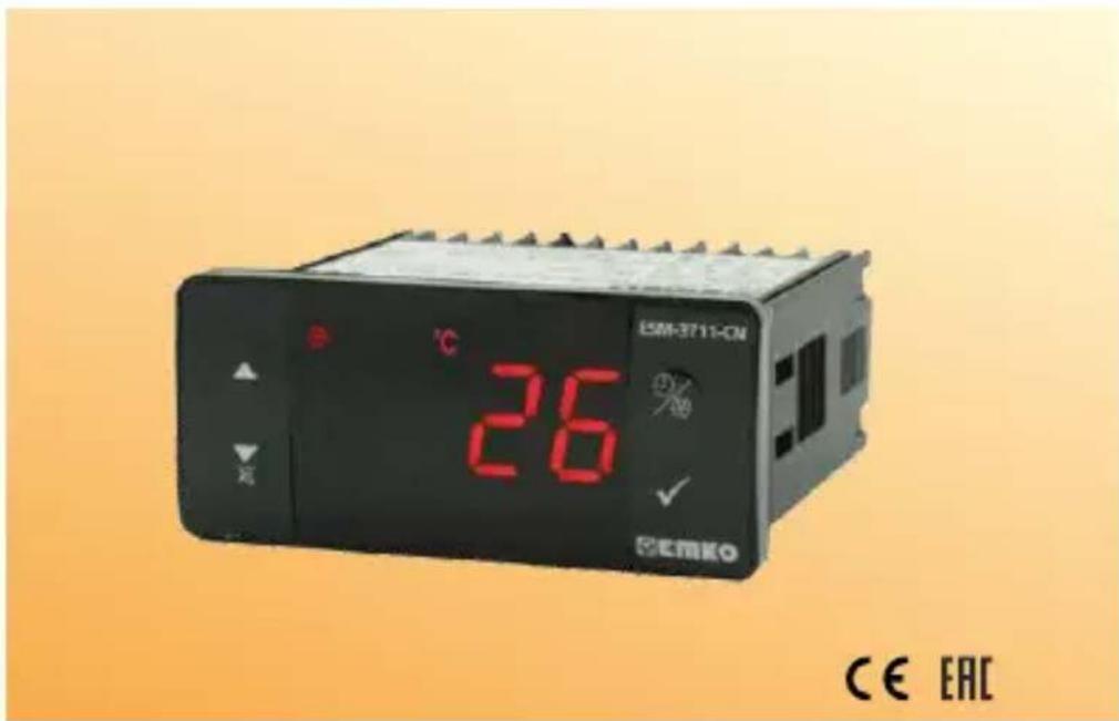
ESM-3711-CN 26 CEMKO CE EACESM-3711-CN 77 x 35 DIN Size Digital, ON / OFF Cooling Controller
- 4 Digits Display
- NTC Input or PTC Input (Must be determined in order.)
- Adjustable temperature offset
- Set value boundaries
- Operation selection of compressor operates continuously, stops or operates periodically in case of sensor defect
- Compressor protection delays
- Defrost time easily changeable from front panel
- Manual defrost capability from front panel
- Defrost parameters
- Alarm parameters
- Adjustable internal buzzer according to the defrost, sensor defect and alarm status
- Defrost time and/or manual defrost and/or temperature set value protection
- Password protection for programming section
- Installing parameters using Prokey
- Remote access, data collecting and controlling with Modbus RTU
- Having CE mark according to European Norms
1.Preface
ESM-3711-CN series cooling controllers are designed for controlling cooling process. They can be used in many applications with their easy-use, On / Off control form and defrost properties. Some application and application fields which they are used are below:
Application Fields
Food
Machine production industries etc...
Applications
Refrigerators
Air Conditioning
Storages
Freezers
etc...
1.1 Environmental Ratings

Operating Temperature : 0 to 50 °C

Max. Operating Humidity : 90% Rh (non-condensing)


Altitude : Up to 2000 m.
Forbidden Conditions:
Corrosive atmosphere
Explosive atmosphere
Home applications (The unit is only for industrial applications)
1.2 General Specifications

flowchart
graph TD
    A["Standard\n230V ( %15) 50/60Hz~ ±"] --> B["ESM-3711-CN\nPower Supply Input"]
    C["NTC, PTC"] --> D["ESM-3711-CN\nSensor Input"]
    D --> E["Compressor Output"]
    E --> F["Cooling Function ON/OFF Operation"]
1.3 Installation
A visual inspection of this product for possible damage occurred during shipment is recommended before installation. It is your responsibility to ensure that qualified mechanical and electrical technicians install this product.
If there is danger of serious accident resulting from a failure or defect in this unit, power off the system and separate the electrical connection of the device from the system.
The unit is normally supplied without a power supply switch or a fuse. Use power switch and fuse as required.
Be sure to use the rated power supply voltage to protect the unit against damage and to prevent failure.
Keep the power off until all of the wiring is completed so that electric shock and trouble with the unit can be prevented.
Never attempt to disassemble, modify or repair this unit. Tampering with the unit may results in malfunction, electric shock or fire.
Do not use the unit in combustible or explosive gaseous atmospheres.
During putting equipment in hole on the metal panel while mechanical installation some metal burrs can cause injury on hands, you must be careful.
Montage of the product on a system must be done with it's fixing clamps. Do not do the montage of the device with inappropriate fixing clamp. Be sure that device will not fall while doing the montage.
It is your responsibility if this equipment is used in a manner not specified in this instruction manual.
1.4 Warranty
EMKO Elektronik warrants that the equipment delivered is free from defects in material and workmanship. This warranty is provided for a period of two years. The warranty period starts from the delivery date. This warranty is in force if duty and responsibilities which are determined in warranty document and instruction manual performs by the customer completely.
1.5 Maintenance
Repairs should only be performed by trained and specialized personnel. Cut power to the device before accessing internal parts.
Do not clean the case with hydrocarbon-based solvents (Petrol, Trichlorethylene etc.). Use of these solvents can reduce the mechanical reliability of the device. Use a cloth dampened in ethyl alcohol or water to clean the external plastic case.
1.6 Manufacturer Company
Manufacturer Company Name :
Emko Elektronik A.Š .DÓSAB Karanfil Sk.No:6 16369 BURSA/TURKEY
Phone : +90 224 261 19 00
Fax : +90 224 261 19 12
Repair and maintenance service information:
Emko Elektronik Sanayi ve Ticaret A.Ş.
Demirtaş Organize Sanayi Bölgesi Karanfil Sk. No:6 16369 BURSA/TURKEY
Phone : +90 224 261 1900
Fax : +90 224 261 1912
2. General Description
text_image
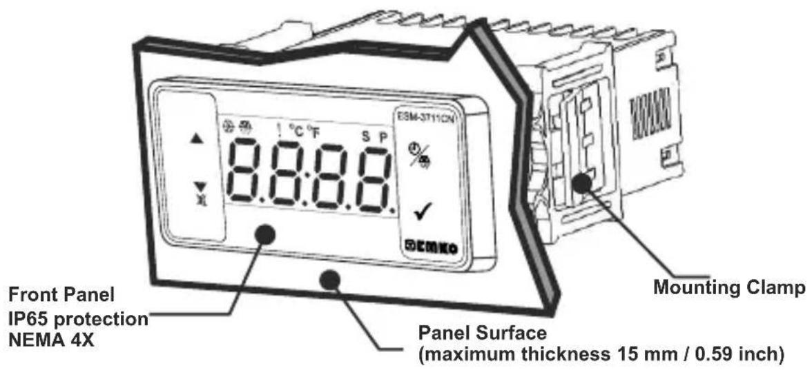
ESM-3711CN 8.8:8.8 Front Panel IP65 protection NEMA 4X Panel Surface (maximum thickness 15 mm / 0.59 inch) Mounting Clamp2.1 Front View and Dimensions of ESM-3711-CN Cooling Controller
text_image
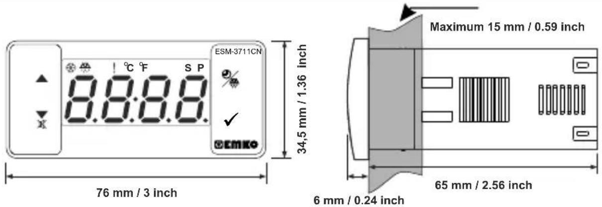
ESM-3711CN 8.8:8.8 °C F S P 76 mm / 3 inch 34,5 mm / 1.36 inch Maximum 15 mm / 0.59 inch 6 mm / 0.24 inch 65 mm / 2.56 inch2.2 Panel Cut-Out
other
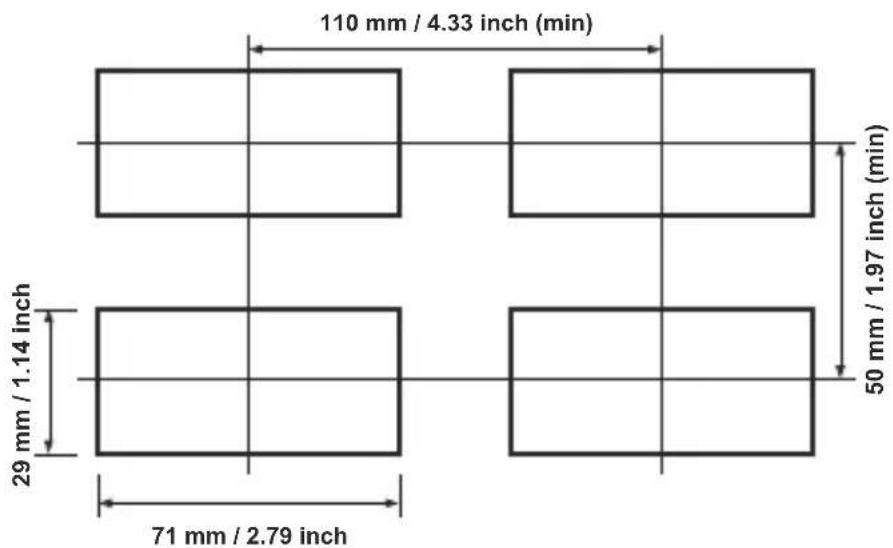
| Dimension | Value | | ----------------- | ----------- | | Top Left | 110 mm / 4.33 inch (min) | | Top Right | 50 mm / 1.97 inch (min) | | Middle Left | 29 mm / 1.14 inch | | Middle Right | 71 mm / 2.79 inch |2.3 Panel Mounting
text_image
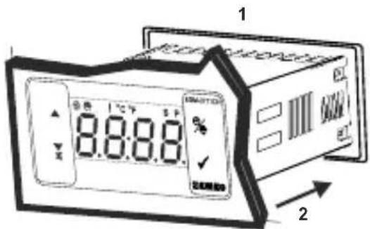
1 8.8.8. SMARTCH E ✓ 定制照明盘 21-Before mounting the device in your panel, make sure that the cut-out is of the right size.
2-Insert the device through the cut-out. If the mounting clamps are on the unit, put out them before inserting the unit to the panel.
text_image
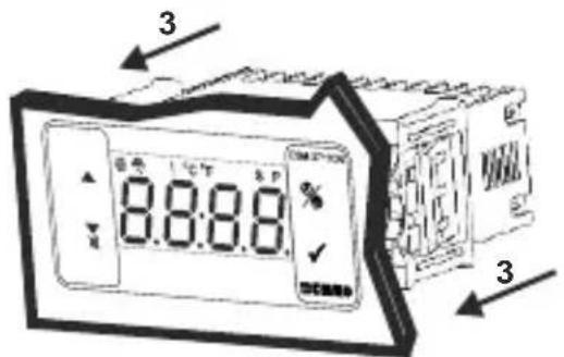
8:8:8.0 3 33- Insert the mounting clamps to the fixing sockets that located left and right sides of device and make the unit completely immobile within the panel
2.4 Removing from the Panel
text_image
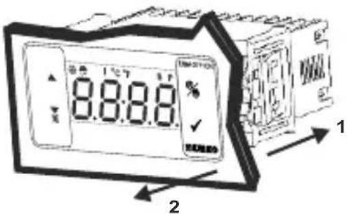
8.8.8.8 1 21-Pull mounting clamps from left and right fixing sockets.
2-Pull the unit through the front side of the panel

Before starting to remove the unit from panel, power off the unit and the related system.
3. Using Prokey
TO USE PROKEY, VALUE OF THE PrC PARAMETER MUST BE '0'. IF PrC=1 AND ▼BUTTON IS PRESSED ErrMESSAGE WILL BE SHOWN. 10s. LATER DEVICE TURNS BACK TO THE MAIN OPERATION SCREEN OR YOU CAN PRESS SET BUTTON TO TURN BACK TO MAIN OPERATION SCREEN.
DOWNLOADING FROM DEVICE TO PROKEY
- The device is programmed by using the parameters.
- Energize the device then put in PROKEY and press ▼ button. [UPL] Message is shown on the display. When the loading has finished, [End] message is shown.
- Press any button to turn back to main operation screen.
- Remove the PROKEY.
NOTE: Err message is shown when an error occurs while programming. If you want to reload, put in PROKEY and press ▼ button. If you want to quit, remove PROKEY and press ▼ button. The device will turn back to main operation screen.
DOWNLOADING FROM PROKEY TO DEVICE
- Switch off the device.
- Put in PROKEY then energize the device.
- When the device is energized, the parameter values in PROKEY, start downloading to the device automatically. At first, HOL message is shown on the display, when loading has finished, End message is shown.
- After 10 seconds device starts to operate with new parameter values.
- Remove the PROKEY.
NOTE: Err message is shown when an error occurs while programming. If you want to reload, switch off the device and put in PROKEY then energize the device. If you want to quit remove PROKEY and press ▼ button. The device will turn back to main operation screen.
4. Electrical Wiring Diagram
text_image
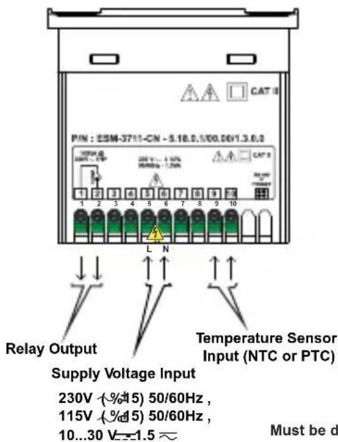
PIN : ESM-3711-CN - 5.18.5.100.06V1.3.6.3 Supply Voltage Input 230V (%%45) 50/60Hz , 115V (%%45) 50/60Hz , 10...30 V=1.5 ~ Relay Output Supply Voltage Input Temperature Sensor Input (NTC or PTC) Must be d4.1 Supply Voltage Input Connection of the Device
Power Supply Connection
text_image
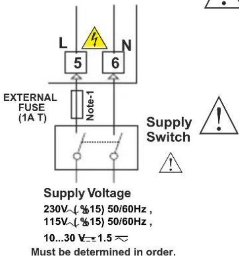
L 5 6 N External FUSE (1A T) Note-1 Supply Switch ! Supply Voltage 230V~(%15) 50/60Hz , 115V~(%15) 50/60Hz , 10...30 V=±1.5~ Must be determined in order.
Make sure that the power supply voltage is the same indicated on the instrument.
Switch on the power supply only after that all the electrical connections have been completed.
Supply voltage range must be determined in order. While installing the unit, supply voltage range must be controlled and appropriate supply voltage must be applied to the unit.
There is no power supply switch on the device. So a power supply switch must be added to the supply voltage input.
Power switch must be two poled for separating phase and neutral, On/Off condition of power supply switch is very important in electrical connection.
External fuse that on power supply inputs must be on phase connection.
External fuse that on — power supply inputs must be on (+) connection.
Note-1 : External fuse is recommended.
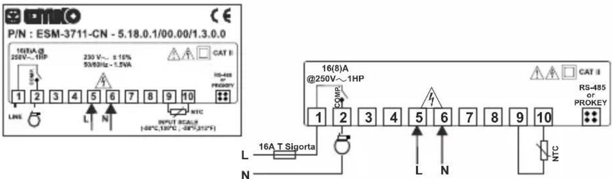
4.2 Device Label and Connection Diagram
230V\~ CONNECTION DIAGRAM
text_image
P/N : ESM-3711-CN - 5.18.0.1/00.00/1.3.0.0 1611A @ 250V~1HP 230 V~ ±10% 50/63Hz - 1.5VA CAT II HS-485 PROKEY LINE L N NTC INPUT SCALB (-08°C,130°C, -08°,312°F) COMP 16(8)A @250V~1HP RS-485 OR PROKEY L N 16A T Sigorta L N NTC5.Front Panel Definition and Accessing to the Menus
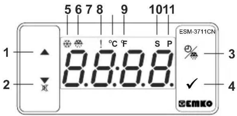
text_image
5 6 7 8 9 1011 1 ▲ ! °C F S P ESM-3711CN 3 2 ▼ 8.8:8.8. ✓ 4 EEMKOBUTTON DEFINITIONS
** It is used to increase the value in the Set screen, Defrost screen and Programming mode.
2. Decrement, Silencing Buzzer and Downloading to Prokey Button :
** It is used to decrease the value in the Set screen, Defrost screen and Programming mode.
** It is used to silence the buzzer.
** If Prc =0, it is used to download from device to prokey.
3. Defrost Button :
** In the main operation screen; if this button pressed, defrost time value will be displayed.
**In the main operation screen; if this button pressed for 3 seconds, manual defrost starts.
4. Set Button :
** In the main operation screen; if this button pressed, set value will be displayed. Value can be changed using increment and decrement buttons. When Set button pressed again, value is saved and returns back to main operating screen.
** To access the programming screen; in the main operation screen, press this button for 5 seconds.
** It is used to saving value in the Set screen, Defrost screen and programming screen.
LED DEFINITIONS
5. Compressor output led :
** This led indicates that compressor output is active. If any of compressor protection time active, this led blinks.
6.Defrost led :
** This led indicates that defrost output is active.
** Blinks once in a second while Defrost delay time.
** Blinks (5 Hz) while entering Defrost time value.
7. Alarm led :
** It is active when low alarm and high alarm statuses.
8.Celcius led :
** Indicates that device is in C mode.
9.Fahrenheit led :
** Indicates that device is in F mode.
10.Set led :
** Indicates that device is in Set value changing mode.
11. Program led :
**Blinks in programming mode.
6. Changing and Saving Temperature Set Value
Main Operation Screen
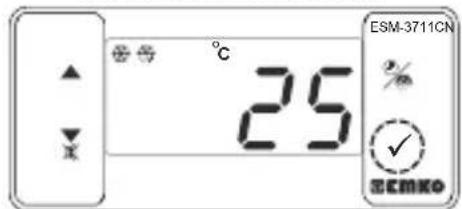
text_image
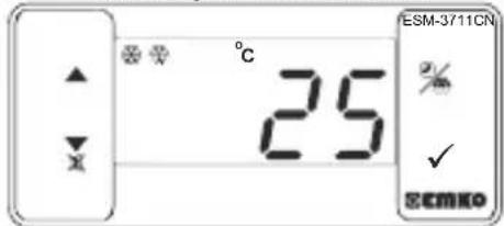
°C 25 ESM-3711CN % ✓ SEMKOWhen SET button pressed "S" led will be active and temperature set value will be displayed.
SET Value Screen
text_image
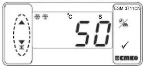
°C S 50 ESM-3711CN % ✓ ECMKOTemperature set value can be changed with increment and decrement buttons.
text_image
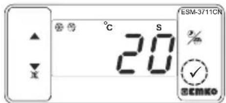
ESM-3711CN ℃ S 20 % ✓ SEMKOWhen SET button pressed temperature set value can be saved.
Main Operation Screen
text_image
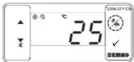
ESM-3711CN 25 % ✓ SEMKO"S" will be inactive and goes back to main operation screen.
Temperature set value parameter (Default=50) MODBUS ADDRESS:40001
Temperature set value, can be programmed between minimum temperature set value 5uL and maximum temperature set value 5uH.
6.1 Changing and Saving Defrost Time Set Value
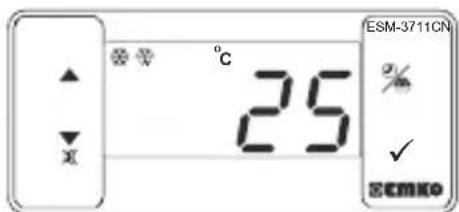
Main Operating Screen
text_image
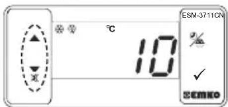
°C 25 ESM-3711CN % ✓ SEMKOWhen defrost button is pressed, defrost time set value is shown and defrost output led starts to fast blink (5 Hz).
Defrost Time Value Screen
text_image
ESM-3711CN 10% ✓ SEMKOChange the defrost time set value with increment and decrement buttons.
Defrost Time Value Screen
text_image
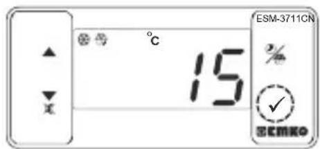
°C 15 % ✓ SEMKO ESM-3711CNPress set button for saving the defrost time set value
Main Operating Screen
text_image
ESM-3711CN 25 % ✓ ECMKODefrost time set value is saved, defrost output led stop the fast blink (5 Hz), main operation screen is shown.

If no operation is performed in defrost time set value changing mode and temperature set value changing mode for 20 seconds, device turns to main operation screen automatically.
6.2 Programming Mode Parameter List
Temperature Unit Selection Parameter (Default = 0) MODBUS ADDRESS:40002
°C selected.
°F selected.

Decimal Seperator Enabling Parameter (Default = 0) MODBUS ADDRESS:40003
Disable.
Enable.

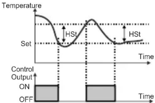
Hysteresis Parameter for Compressor Output (Default = 1) MODBUS ADDRESS:40004
from 1 to 20°C for NTC (-50°C, 100°C) or PTC (-50°C, 150°C),
from 1 to 36°F for NTC (-58°F, 212°F) or PTC (-58°F, 302°F),
from 0.1 to 10.0^ for NTC(-50.0°C,100.0°C) or PTC (-50.0°C,150.0°C),
from 0.1 to 18.0°F for NTC (-58.0°F,212.0°F) or PTC (-58.0°F,302.0°F),
In ON/OFF control algorithm, temperature value is tried to keep equal to set value by opening or closing the last control element. ON/OFF controlled system, temperature value oscillates continuously. Temperature value's oscillation period or amplitude around set value changes according to controlled system. For reducing oscillation period of temperature value, a threshold zone is formed below or around set value and this zone is named hysteresis.
line
| Time | Temperature | |------|-------------| | Start | High | | Peak | High | | End | Low |
Minimum Temperature Set Value Parameter (Default = Minimum Value of Device Scale) MODBUS ADDRESS:40005
Temperature set value can not be lower than this value.
This parameter value can be adjusted from minimum value of device scale to maximum temperature set value parameter S_uH

Maximum Temperature Set Value Parameter (Default = Maximum Value of Device Scale) MODBUS ADDRESS:40006
Temperature set value can not be greater than this value.
This parameter value can be adjusted from minimum temperature set value parameter to maximum value of the device scale

Sensor Offset Parameter (Default = 0) MODBUS ADDRESS:40007
from -20 to 20 °C for NTC(-50°C, 100°C) or PTC(-50°C, 150°C),
from -36 to 36 °F for NTC(-58°F, 212°F) or PTC(-58°F, 302°F),
from -10.0 to 10.0°C for NTC(-50.0°C,100.0°C) or PTC(-50.0°C,150.0°C),
from -18.0 to 18.0°F for NTC(-58.0°F,212.0°F) or PTC(-58.0°F,302.0°F),

Operating Type Parameter (Default = 1) MODBUS ADDRESS:40008
If parameter value is '0' device skips to TLS parameter
Heating
Cooling
Defrost Time Parameter (Default =1 0) MODBUS ADDRESS:40009
It can be adjusted from 0 to 999 minutes. If it is selected 0 automatic or manual defrost is not performed.

Defrost Repeat Cycle Parameter (Default = 1) MODBUS ADDRESS:40010
It can be adjusted from 1 to 99 hours.

Defrost at Power On Parameter (Default = 0) MODBUS ADDRESS:40011
System does not go through a defrost cycle at start up
System goes through a defrost cycle at start up

Defrost Delay at Power On Parameter (Default = 0) MODBUS ADDRESS:40012
It can be adjusted from 0 to 99 minutes. This parameter can be observed if defrost at power on parameter is 1.

Display Status During Defrost Parameter (Default = 3) MODBUS ADDRESS:40013

The temperature is displayed during defrost.
Temperature value at the start of a defrost is displayed during defrost.
Set value is displayed during defrost.
DEF Is displayed to indicate a defrost is in progress.

Compressor Start Delay at Power On Parameter (Default = 0) MODBUS ADDRESS:40014
When power is first applied to the device, compressor is on when this time delay is expired. It can be adjusted from 0 to 20 minutes.

Compressor Stop-Start Delay Parameter (Default = 0) MODBUS ADRES:40015
When compressor is inactive, this time delay must be expired for activation of the compressor. It can be adjusted from 0 to 20 minutes.

Compressor Start-Start Delay Parameter (Default = 0) MODBUS ADRES:40016
This time delay must be expired between two activation of the compressor. It can be adjusted from 0 to 20 minutes.

Sensor Defect Parameter (Default = 0) MODBUS ADRES:40017
Compressor is OFF in case of sensor defect.
Compressor is ON in case of sensor defect.
Compressor operates periodically according to P on and P off time periods in case of sensor defect.

Compressor is active during this time period in case of probe defect (Default = 0) MODBUS ADRES:40018
If probe defect parameter is 2, then this parameter is observed. It can be adjusted from 0 to 99 minutes.

Compressor is inactive during this time period in case of probe defect (Default = 0) MODBUS ADRES:40019
If probe defect parameter [P_dF] is 2, then this parameter is observed. It can be adjusted from 0 to 99 minutes.

Temperature Alarm Function Selection Parameter (Default = 0) MODBUS ADRES:40020
Alarm function is inactive.
Absolute alarm is selected. If temperature lower than _uH and higher than _uH , then alarm is on.

Relative alarm is selected. Alarm operates according to the set value. If temperature is below (Set RUL) or above (Set H, H), alarm occurs.

Temperature Minimum Alarm Parameter (Default = Minimum Value of Device Scale) MODBUS ADRES:40021
For temperature alarm function selection parameter = 1 (Absolute alarm), this parameter value is can be adjust from minimum value of device scale to temperature alarm maximum parameter value, for temperature alarm function selection parameter = 2 (Relative alarm), this parameter value is can be adjusted 0 to %50 of the device scale
Temperature Alarm Maximum Parameter (Default = Maximum Value of Device Scale) MODBUS ADRES:40022
For temperature alarm function selection parameter = 1 (Absolute alarm), this parameter value is can be adjusted from temperature alarm minimum parameter value to maximum value of device scale, for temperature alarm function selection parameter = 2 (Relative alarm), this parameter value is can be adjusted 0 to %50 of the device scale

Temperature Alarm On Delay Time Parameter(Default = 0)MODBUS ADDRESS:40023
Temperature alarm on delay time can be defined with this parameter.
It can be adjusted from 0 to 99 minutes.

Temperature Alarm Delay After Power On Parameter(Default = 0) MODBUS ADRES:40024
When power is first applied to the device, this time delay must be expired for activation of temperature alarm. It can be adjusted from 0 to 99 minutes.

Buzzer Function Selection Parameter (Default = 0) MODBUS ADDRESS:40025
Buzzer is inactive.
Buzzer is active during defrost operation.
Buzzer is active if an alarm occurs.
Buzzer is active during sensor failures.
Buzzer is active during defrost operation, alarm or sensor failures.

Buzzer is active during this time (Default = - - - ) MODBUS ADDRESS:40026
If buzzer function selection parameter value =0 , this parameter can not be observed. Buzzer stays active during this time. It can be adjusted from 1 to 99 minutes. When this parameter is 1, if decrement button is pressed, ·s·s is observed. In this condition buzzer is active till buzzer silence button is pressed.

Button Protection Parameter (Default = 4) MODBUS ADDRESS:40027
There is no protection.
Defrost time can not be changed and manual defrost is not available.
Temperature Set value can not be changed.
Defrost time set value and temperature set value can not be changed. Manual defrost is not available.
Defrost time value can not be changed, manual defrost is available..

Communication Mode Selection Parameter (Default = 0) MODBUS ADDRESS:40028
PROKEY communication selected.
Rs485 communication selected.

Slave ID Parameter (Default = 1) MODBUS ADDRESS=40029
Device communication address parameter (1 to 247).

ON/OFF Parameter (Default = 0) MODBUS ADDRESS:40030
When device energized; if ▲ (increment button) pressed for 10 seconds, device stops controlling and [...] screen will be displayed. If ▲ (increment button) pressed again for 10 seconds, device continues controlling and display changes back to main operating
screen.
ON/OFF function with▲ button is not available.
ON/OFF function with▲ button is available.

Programming Section Accessing Password (Default = 0) MODBUS ADDRESS:40031
It is used for accessing to the programming section. It can be adjusted from 0 to 999. If it is selected 0, password will not be asked if password selected '12', only HSE dE and drL parameters will be accessible.
6.3 Modbus Adresses of Device Status Parameters (Read Input Register)
MODBUS ADDRESS:30001
MODBUS ADDRESS:30002
MODBUS ADDRESS:30003
Temperature Value
Reserved
Led Status : 0.bit°C Led, 5.bit Defrost Led,
6.bit Compressor Led, 7.bit Alarm Led
13.bit Program Led, 14.bit Set Led
MODBUS ADDRESS:30004
Device Status : 0.bit Alarm Status
1.bit Buzzer Status
2.bit Sensor Lost Status
7.bit Defrost Status
MODBUS ADDRESS:30005
Output Status
MODBUS ADDRESS:30006
Device Type and Device Version
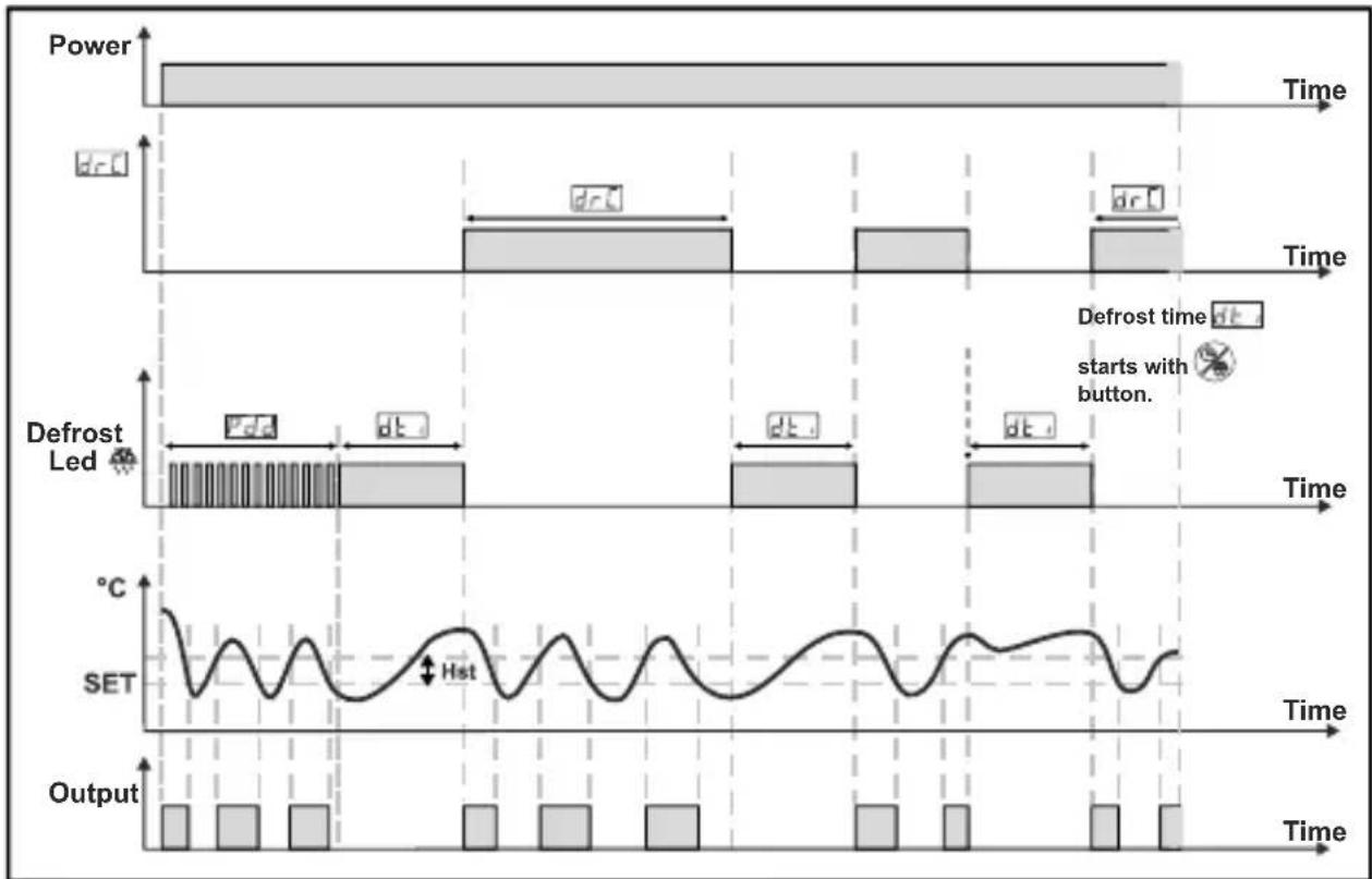
6.4 Operation Graphics of ESM-3711-CN Cooling Controller
1-If defrost time parameter dt_1 ≥ 1 , Defrosting repeat cycle dr_C ≥ 1 , Defrost at Power On Parameter P_od = 1 and Defrost Delay at Power On Parameter P_dd ≥ 1 ;
line
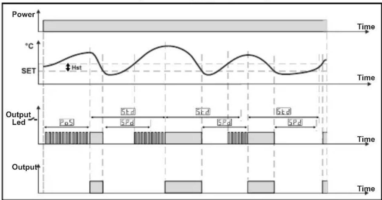
| Time | Power (dr) | Defrost Led (Pd) | Defrost Led (dt) | SET (Hz) | |------|------------|------------------|------------------|----------| | 0 | 1 | 0 | 0 | 0 | | 1 | 1 | 0 | 0 | 0 | | 2 | 1 | 0 | 0 | 0 | | 3 | 1 | 0 | 0 | 0 | | 4 | 1 | 0 | 0 | 0 | | 5 | 1 | 0 | 0 | 0 | | 6 | 1 | 0 | 0 | 0 | | 7 | 1 | 0 | 0 | 0 | | 8 | 1 | 0 | 0 | 0 | | 9 | 1 | 0 | 0 | 0 | | 10 | 1 | 0 | 0 | 0 | | 11 | 1 | 0 | 0 | 0 | | 12 | 1 | 0 | 0 | 0 | | 13 | 1 | 0 | 0 | 0 | | 14 | 1 | 0 | 0 | 0 | | 15 | 1 | 0 | 0 | 0 | | 16 | 1 | 0 | 0 | 0 | | 17 | 1 | 0 | 0 | 0 | | 18 | 1 | 0 | 0 | 0 | | 19 | 1 | 0 | 0 | 0 | | 20 | 1 | 0 | 0 | 0 | | 21 | 1 | 0 | 0 | 0 | | 22 | 1 | 0 | 0 | 0 | | 23 | 1 | 0 | 0 | 0 | | 24 | 1 | 0 | 0 | 0 | | 25 | 1 | 0 | 0 | 0 | | 26 | 1 | 0 | 0 | 0 | | 27 | 1 | 0 | 0 | 0 | | 28 | 1 | 0 | 0 | 0 | | 29 | 1 | 0 | 0 | 0 | | 30 | 1 | 0 | 0 | 0 | | 31 | 1 | 0 | 0 | 0 | | 32 | 1 | 0 | 0 | 0 | | 33 | 1 | 0 | 0 | 0 | | 34 | 1 | 0 | 0 | 0 | | 35 | 1 | 0 | 0 | 0 | | 36 | 1 | 0 | 0 | 0 | | 37 | 1 | 0 | 0 | 0 | | 38 | 1 | 0 | 0 | 0 | | 39 | 1 | 0 | 0 | 0 | | 40 | 1 | 0 | 0 | 0 | | Note: Refrost time is marked as 'starts with button.'2- If Compressor Start Delay at Power On Parameter 5 ≥ Compressor Stop-Start Delay Parameter is ≥ Compressor Start-Start Delay Parameter is ≥ 1 then ;
6.5 Entering To The Programming Mode, Changing and Saving Parameter
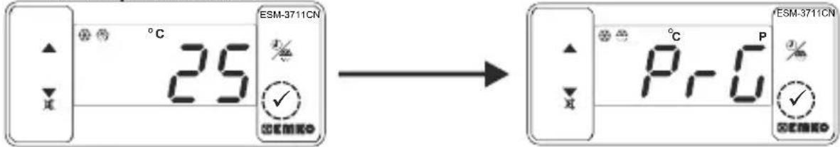
Main Operation Screen
text_image
°C 25 ESM-3711CN ✓ SEM → °C P ✓ SEM ESM-3711CNWhen SET button is pressed for 5 seconds, "PR" led starts to blink. If programming mode entering password is different from 0, programming mode entering screen will be observed.
Note1: If programming mode accessing password is 0, Temperature Unit Selection parameter is F-F observed instead of programming screen Pr-U
Programming Mode Entering Screen
Press SET button for accessing to the password entering screen.
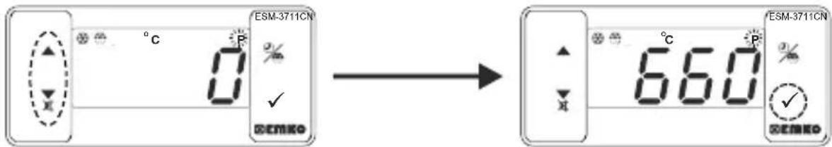
text_image
ESM-3711CN 0 ✓ SEMKO 660 ESM-3711CN 0 ✓ SEMKOPassword Entering Screen
Enter programming mode accessing password with increment and decrement buttons.
Password Entering Screen
Press SET/OK button for entering the password.
Note2: If programming mode accessing password is 0, only three parameters are accessible, and the parameter values can be changed.
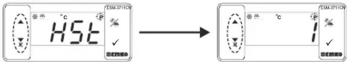
Programming Screen
text_image
HSL ESM-3711CN ✓ SEMKO ESM-3711CN ✓ SEMKOPress SET button for accessing to the parameter value. Press increment button for accessing to the next parameter, press decrement button for accessing to the previous parameter.
Hysteresis Value for Compressor Output
Change the value with increment and decrement buttons.
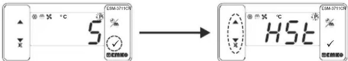
text_image
ESM-3711CN 5 EEMKO HSL ESM-3711CN %Hysteresis Value for Compressor Output
Press set button for saving the parameter.
Hysteresis Parameter for Compressor
Press increment button for accessing to the next parameter, press decrement button for accessing to the previous parameter

If no operation is performed in programming mode for 20 seconds, device turns to main operation screen automatically..
7. Failure Messages in ESM-3711-CN Cooling Controller
1. 56r Screen Blinking
Sensor failure. Sensor connection is wrong or there is no sensor connection. If buzzer function selection parameter buF is 3 or 4, internal buzzer starts to operate.
2- Blinking the Screen Value
If temperature higher than the alarm parameters limit, value on the screen starts to blink.
Example-1: If alarm function selection parameter [ALS] In programming section is 1(Absolute alarm) and minimum alarm parameter [RU-L] is 20;
When temperature is less than 20^ C, value on the screen starts to blink. Also if buzzer function selection parameter _uF is 2 or 4, then internal buzzer is on.
Example-2 : If alarm function selection parameter ^RLS in programming section is 1 (Absolute Alarm) and maximum alarm parameter ^RH is 50
When temperature is above 50 °C, value on the screen starts to blink. Also buzzer function selection parameter F is 2 or 4, then internal buzzer is on.
8. Manual Defrost Operation with Defrost Button
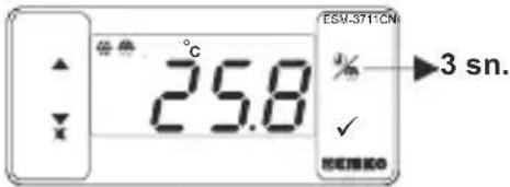
text_image
ESV-371CN 25.8 °C % 3 sn. ✓ RENEKOWhile defrost time parameter value dt_1 ≥ 1 , button protection parameter value Prt = 0 or 2 and defrost output is inactive, in main operation screen if defrost button is pressed for 3 seconds defrost operation starts and defrost led becomes active. If defrost button pressed for 3 seconds while defrost continues, defrost is finished and defrost led becomes inactive
9. Specifications
Device Type
Housing&Mounting
Protection Class
Weight
Environmental Ratings
Storage / Operating Temperature:
Storage / Operating Humidity
Installation
Overvoltage Category
Pollution Degree
Operating Conditions
Supply Voltage and Power
Temperature Sensor Input
NTC input type
PTC input type
Accuracy
Sensor Break Protection
Sampling Cycle
Control Form
Relay Outputs
output)
Display
LED
Internal Buzzer
Approvals
: Cooling Controller
: 76mm x 34.5mm x 71mm plastic housing for panel Mounting. Panel cut-out is 71x29mm.
: NEMA 4X (Ip65 at front, Ip20 at rear).
: Approximately 0.20 Kg.
: Standard, indoor at an altitude of less than 2000 meters with none condensing humidity.
: -40 °C to +80 C / -30 C to +80 C
: 90 % max. (None condensing)
: Fixed installation
: Ⅱ.
: II, office or workplace, none conductive pollution
: Continuous
: 230V\~(%15) 50/60Hz - 1.5VA
: 115V\~(%15) 50/60Hz - 1.5VA
: 24V(10-2015) 50/60Hz - 1.5VA V=1.5W
: NTC or PTC
: NTC (10 kΩ @25 °C)
: PTC (1000 Ω @25 °C)
: ± 1 % of full scale for thermoresistance
: Upscale
: 3 samples per second
: ON / OFF
16(8) A@250 V ∼ for Resistive load (Compressor
(Electrical life : 100.000 switching at full load)
: 14 mm Red 4 digits LED Display
: S (Green), P (Green), °C (Yellow), °F (Yellow), Alarm (Red), Defrost (Red), Compressor Output (Red)
: ≥83dB
: EAC,CE
10. Ordering Information
| ESM-3711-CN(77x35 DIN Size) | A B C D E F G H I / | U | V | V Z | |||||
| A | Supply Voltage | ||||||||
| 3 | 24V~ (±%15) 50/60Hz - 1.5VA | ||||||||
| 4 | 115V~ (±%15) 50/60Hz - 1.5VA | ||||||||
| 5 | 230V~ (±%15) 50/60Hz - 1.5VA | ||||||||
| 8 | 10 - 30 V === | ||||||||
| BC | Input Type | Scale(°C) | |||||||
| 12 | PTC (Note-1) | -50°C/-58°F; 150°C/302°F | |||||||
| 18 | NTC (Note-1) | -50°C/-58°F; 100°C/212°F | |||||||
| E | Compressor Output | ||||||||
| 1 | Relay Output (16(8) A@250 V ~ at resistive load, 1 NO) | ||||||||
| V | Temp. Sensor which is given with ESM-3711-CN | ||||||||
| 0 | None | ||||||||
| 1 | PTC-M6L40.K1.5 (PTC Air Probe with 1.5 mt silicon cable) | ||||||||
| 2 | PTCS-M6L30.K1.5.1/8" (PTC Liquid Probe with1.5 mt silicon cable) | ||||||||
| 3 | NTC-M5L20.K1.5 (NTC Sensor, thermoplastic moulded with 1.5 m cable for cooling application) | ||||||||
| 4 | NTC-M6L50.K1.5 (NTC Sensor, stainless steel housing with 1.5 m cable for cooling application) | ||||||||
| 9 | Customer | ||||||||
All order information of ESM-3711-CN Cooling Controller are given on the table at left. User may form appropriate device configuration from information and codes that at the table and convert it to the ordering codes. Firstly, supply voltage then other specifications must be determined. Please fill the order code blanks according to your needs.
Please contact us, if your needs are out of the standards.
Note-1: If input type is selected PTC or NTC (BC= 12, 18), Temperature sensor is given with the device. For this reason, if input type is selected as PTC, sensor type (V = 0,1 or 2) or if input type is selected as NTC, sensor type (V = 0,3 or 4) must be declared in ordering information.
11.Optional Accessories
1.RS-485 Module
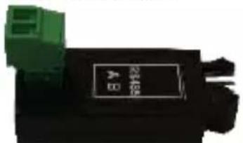
text_image
DC 20kΩ 10kΩRS-485 Communication Interface
2.PROKEY Programming Module

The device is programmed(Upload or Download) by using the parameters.

text_image
~ ⇒ Vac, ==⇒ Vdc ⇒ Vdc or Vac can be applied~
Thank you very much for your preference to use Emko Elektronik products, please visit our web page to download detailed user manual.
www.emkoelektronik.com.tr
text_image
E5M-3711-CN 26 % EMKO CE EACtext_image
°C S 20% SEMKOline
| Time | Temperature | Sollwert | |------|-------------|----------| | 0 | High | Low | | Peak | High | Low | | Mid | Medium | Low | | End | Low | Low |
text_image
0% ✓ SEMKO → 6.60 ✓ SEMKOtext_image
5% ✓ HSL ✓ ℃EMKOnatural_image
Close-up of a black electrical component with a green connector and a white label (no readable text or symbols)text_image
8:00:00 3 3Désactiver. Activer.

line
| Time Period | Temperature | | ----------------- | ----------- | | Start | High | | Peak | High | | End | Low |
: 90% max. (Aucune condensation)
: Installation fixe
: ||.
text_image
DC 2014 DCInterface de communication RS-485
2. Module de programmation PROKEY

line
| Tiempo | Temperature | | ------ | ----------- | | Start | High | | Peak | Low | | High | High | | End | Low |