UV500 - Detector VOLTCRAFT - Free user manual and instructions
Find the device manual for free UV500 VOLTCRAFT in PDF.
| Product type | UV radiation detector |
| Brand | Voltcraft |
| Model | UV500 |
| Dimensions (L x W x D) | 200 x 68 x 30 mm |
| Weight | 383 g |
| Power supply | 9 V battery (6LR61) or optional 9 V DC power supply |
| Measurement ranges | 0.000 to 1.999 mW/cm² and 0.00 to 19.99 mW/cm² |
| Accuracy | ±(4% + 2 digits) of the measurement range |
| Resolution | 0.001 mW/cm² / 0.01 mW/cm² |
| UV spectral range | 290 to 390 nm (UV-B to UV-A) |
| Interface | RS232 (3.5 mm mono jack) |
| Main functions | UV measurement, hold (HOLD), peak recording (REC), zero reset, range selection, auto power off |
| Display | LCD screen |
| Sensor | UV sensor with cosine filter and protective cap |
| Operating temperature | 0 to +50 °C, humidity <85% RH |
| Storage temperature | 0 to +50 °C, humidity <50% RH |
| Cleaning and maintenance | Clean the housing with a slightly damp antistatic cloth; clean the sensor with compressed air and a fine brush; calibrate once a year |
| Safety | Do not use in ATEX areas; avoid strong magnetic fields; follow safety instructions |
Frequently Asked Questions - UV500 VOLTCRAFT
User questions about UV500 VOLTCRAFT
0 question about this device. Answer the ones you know or ask your own.
Ask a new question about this device
Download the instructions for your Detector in PDF format for free! Find your manual UV500 - VOLTCRAFT and take your electronic device back in hand. On this page are published all the documents necessary for the use of your device. UV500 by VOLTCRAFT.
USER MANUAL UV500 VOLTCRAFT
GB Operating instructions
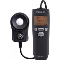
UV-500 UVA + UVB meter
Item No. 1666061 Page 15 - 27
F Mode d'emploi
www.business.conrad.at
text_image
DC IN DC 9V - +- Introduction......16
- Explanation of symbols....16
- Intended use....17
- Delivery content....17
- Safety instructions .... 18
- Product overview 19
- Product description....20
- Power supply 20
a) Inserting or changing the battery 20
b) Connect power supply (optional) 21
- Setup 21
a) Connecting the sensor....21
b) Switching the measuring instrument on and off 21
- Taking measurements....22
a) Performing the UV measurement 22
b) Zero adjustment....22
c) Holding the measured value ("HOLD") 22
d) Recording the measured value peaks ("REC"). 23
e) Automatic shut-off feature 23
- RS232 port....24
- Cleaning and maintenance....25
a) General information....25
b) Cleaning the casing....25
c) Cleaning the sensor....25
- Disposal....26
- Troubleshooting....26
- Technical data....27
1. Introduction
Dear customer,
Thank you for purchasing this Voltcraft® product.
Voltcraft ^® produces high-quality measuring, charging and network devices that offer outstanding performance and innovation.
With Voltcraft ^® , you will be able to cope with even the most difficult tasks whether you are an ambitious hobby user or a professional user. Voltcraft ^® offers you reliable technology at an extraordinarily favourable cost-performance ratio. We are confident that starting with Voltcraft ^® will be the beginning of a long, successful relationship. We hope you enjoy your new Voltcraft ^® product!
If there are any technical questions, please contact:
International: www.conrad.com/contact
United Kingdom: www.conrad-electronic.co.uk/contact
2. Explanation of symbols

The symbol with an exclamation mark in a triangle is used to highlight important information in these operating instructions. Always read this information carefully.

The arrow symbol indicates special information and tips on how to use the product.

This product has been CE tested and complies with the necessary national and European regulations.
3. Intended use
The UV-500 UV meter allows precise measurement of radiant power of invisible ultraviolet radiation (UVA and UVB) in the range of 0 to 20 mW/cm ^2 .
The UV sensor is equipped with a cosine correction filter to determine high-precision readings.
The meter can be ppositioned so that the display is clearly visible with the rear clamp holder.
The meter is powered by a standard 9 V block battery. In addition, the meter can be operated via the DC socket with an optional plug-in power supply. The power supply must provide a stabilised voltage of 9 V/DC. In power supply mode, the internal battery is disabled.
The meter does not have ATEX protection. Do not operate it in potentially explosive atmospheres (Ex).
Do not operate the camera under adverse environmental conditions such as flammable gases, vapours or solvents.
Any use other than that described above is not permitted and may damage the product. Furthermore, there are dangers such as short circuit, fire, electric shock etc.
The product must not be modified or reassembled!
Always observe the safety information in these instructions.
Using this product for any purposes other than those described above may damage the product and result in a short circuit, fire or electric shock. The product must not be modified or reassembled!
Read the operating instructions carefully and keep them in a safe place for future reference.
4. Delivery content
- UV-500 UV meter
- 9 V block battery
• UV sensor with removable protective cap - Operating instructions

Up-to-date operating instructions
Download the latest operating instructions via the link www.conrad.com/downloads or scan the QR code. Follow the instructions on the website.
5. Safety instructions

These instructions contain important information on how to use the device correctly. Please read them carefully before using the device for the first time.
Damage caused due to failure to observe these instructions will void the warranty. We shall not be liable for any consequential damage. We shall not be liable for damage to property or personal injury caused by incorrect handling or failure to observe the safety information! Such cases will void the warranty/guarantee.
• This device was shipped in a safe condition.
- To ensure safe operation and to avoid damaging the device, always observe the safety information and warnings in these instructions.
- Unauthorised conversion and/or modification of the device is not permitted for safety and certification reasons.
- Consult an expert when in doubt about the operation, safety or connection of the device
- Meters and their accessories are not toys and must be kept out of the reach of children.
- Always comply with the accident prevention regulations for electrical equipment when using the product in commercial facilities.
- In schools, educational facilities, hobby and DIY workshops, measuring instruments must be used under the responsible supervision of qualified personnel. The same applies when the meter is used by people with reduced physical and mental capabilities.
- Do not use in the immediate vicinity of strong magnetic or electromagnetic fields, transmitter aerials or RF generators. These may distort the measurements.
- If you suspect that safe operation is no longer possible, stop using the device immediately and prevent unauthorised use. Safe operation can no longer be assumed if:
- There are signs of damage
- The device does not function properly
- The device was stored under unfavourable conditions for a long period of time
- The device was subjected to rough handling during transport.
- Do not switch the device on immediately after it has been brought from a cold room into a warm one. The condensation generated may destroy the product. Leave the device switched off and allow it to reach room temperature.
- Do not leave packaging material lying around carelessly, as it may become a dangerous toy for children.
- Store the device in a safe place where it cannot fall down! Otherwise, this could cause injuries.
- To prevent battery leakage, remove the battery if you do not plan to use the product for an extended period. Leaking or damaged batteries may cause acid burns if they come into contact with your skin. Always use protective gloves when handling damaged batteries.
- Batteries must be kept out of the reach of children. Do not leave batteries lying around as there is a risk that children or pets may swallow them.
- Observe the safety information in each section.
6. Product overview
text_image
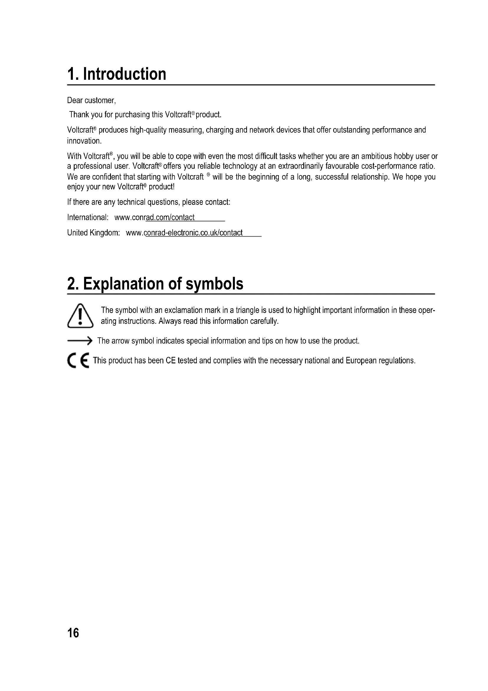
VOLTCRAFT. UV-500 HOLD REC MAX MIN -8.8.8.8.8 mW/cm² POWER +OLD REC 1 23 nW/cm² 7 6 8 9 10 11 12 13 OPEN 14 15 16 171 Sensor connection socket
2 Display
3 "HOLD" button
4 "POWER" on/off button
5 Zero adjustment and range selection button "2" for measurement range 0.000 – 1.999 mW/cm²
6 Range selection button "20" for measurement range 0.00 - 19.99 mW/cm²
7 "REC" button
8 Tripod thread (1/4" UNC 20)
9 Fold-out stand clamp
10 RS232 interface (3.5 mm jack socket, mono)
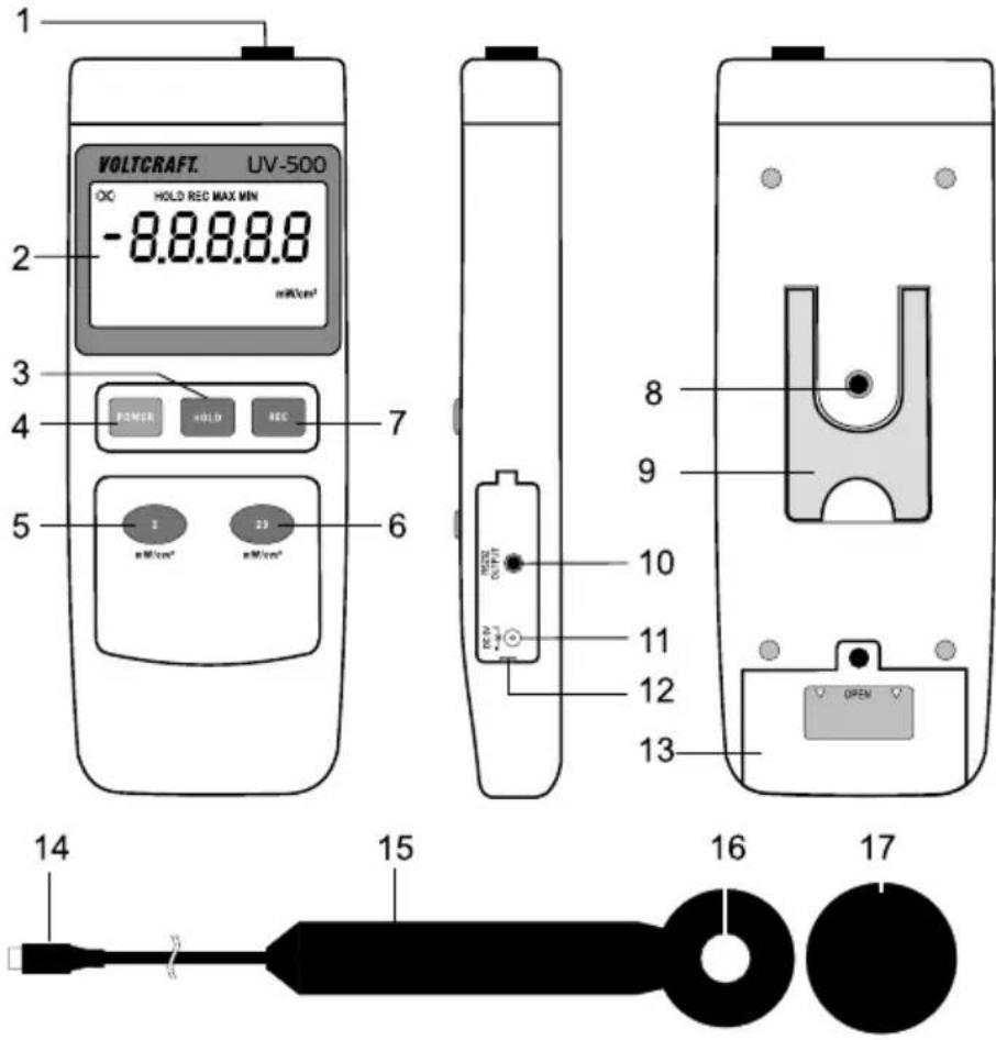
11 Power supply socket 9 V/DC (5.5 mm x 2.5 mm)
12 Opening recess for socket cover
13 Battery compartment
14 Sensor connection plug
15 Sensor handle
16 UV sensor head
17 Sensor protective cover
7. Product description
The UV meter allows precise measurement of radiant power of invisible ultraviolet radiation (UVA and UVB). The UV radiation measurement finds its application in industrial sectors such as welding work (arc), electronics, photochemical processes or printing applications.
The device can also be used e.g. for laboratory tasks, in agriculture and horticulture. This includes weather and growth studies as well as UV sterilisation, etc.
In the private sector, the meter can be used to easily and precisely determine the radiant power of solariums or the sun, etc.
8. Power supply
The meter can be used as a mobile device with a battery or a rechargeable battery. During stationary operation or long-term measurements, an optional power supply can be connected.

When connecting a power supply, the connection between the battery and the meter is automatically interrupted. So the battery does not need to be removed for power supply operation.
a) Inserting or changing the battery
- Before first use or when the battery change symbol appears in the upper left hand corner of the display, a new, fully charged battery must be inserted.
- When changing the battery, make sure that the meter is turned off.
- Use a suitable Phillips screwdriver to unscrew the screw on the battery compartment (13).
- Slide the battery compartment cover off the device in the direction of the arrow.
- Connect a new battery to the battery clip, observing the correct polarity. Insert the battery into the meter. Make sure that the connection cables are not pinched.
- Close the battery compartment in reverse order and screw it back in carefully.
b) Connect power supply (optional)
- The power supply must provide a stabilised voltage of 9 V/DC and a current of at least 300 mA.
-
The DC barrel plug must have the following specifications:
-
Outer diameter 5.5 mm
- Inner diameter 2.5 mm
-
Polarity: Inside positive pole, outside negative pole.
-
To connect the power supply, open the side cover (12). Use a small flat-head screwdriver for this purpose, for example.
- Insert the DC barrel plug of the power supply into the "DC IN" socket.
- Connect the mains adapter to a common household wall socket.

The wall socket must be nearby and easily accessible.
After completion of the measurement, disconnect the power supply from the meter and close the cover.
9. Setup
a) Connecting the sensor

The sensor is a high-precision component that wears out due to excessive humidity and thus becomes inaccurate. Therefore, the sensor head should always be stored in as dry an environment as possible.
It is also recommended that the sensor be stored in an airtight foil bag. Put a packet of dry granules in the foil bag. Replace or regenerate these dry granules on a regular basis to ensure a dry storage environment.
Remove the sensor from the bag for measurement purposes only. This measure extends the service life of the UV sensor. Otherwise, the sensitivity decreases and the recalibration interval is shortened.
When connecting the sensor, make sure that the meter is turned off.
Insert the sensor connection plug (14) into the sensor socket (1) on the meter, observing the correct polarity. The flat side of the plug should thus face the back of the meter.
b) Switching the measuring instrument on and off
- Use the "POWER" on/off button (4) to turn the meter on and off. Each time you press the button, the device turns on and off.
- The meter will turn on with a short beep and display the start screen with all display segments for approx. 3 seconds.
• After the display test is completed, the display shows the current measured value. - Press the on/off button to turn off the device. The device turns off with a long beep.
10. Taking measurements

In order to obtain precise measured values, the measuring instrument must be adjusted to the ambient temperature. Allow the device to adjust to the ambient temperature after relocation.
Lengthy
UV measurements on light sources with high temperatures can cause self-heating of the meter and thus a faulty measurement if the measuring distance is small. In order to obtain precise measured values, remember the following rule of thumb: The higher the temperature, the greater the measuring distance and the shorter the measuring time.
a) Performing the UV measurement
To perform the UV measurement, proceed as follows:
- Put the meter into operation. After turning on, the meter is always in the large measurement range of 20 mW/cm². This range is intended for measurements from 2 to 20 mW/cm².
-Remove the sensor protective cap from the sensor. - Align the sensor surface as perpendicular as possible to the light source.
-The measured value appears on the display. - Change the measurement range to perform measurements less than 2 mW/cm^2 . To do this, press the button with the inscription “2” (5). To switch the measurement range, press the respective range button “2” (5) or “20” (6).
- If “- - - -” appears on the display, the measurement range has been exceeded. Switch to a larger measurement range if possible.
- Turn off the meter when the measurement is completed. Replace the sensor protective cap.
b) Zero adjustment
To achieve high accuracy, the meter can perform zero adjustment. Zero adjustment is only possible and useful if the display shows a measured value of ≤0.1 mW/cm^2 .
To perform zero adjustment, proceed as follows:
-Cover the sensor head with the lightproof sensor cover (17).
- Press and hold down the "2 mW/cm ^2 " range button (5) for approx. 2 seconds. Zero adjustment is signalled with a beep. The measured value on the display is reset to zero.
c) Holding the measured value ("HOLD")
The current measured value can be held to obtain a longer reading time. To hold the measured value, press the "HOLD" button.
The keystroke is signalled with a beep. The measured value and the "HOLD" symbol appear on the display.
To disable the function, press the "HOLD" button again. "HOLD" disappears from the display.
d) Recording the measured value peaks ("REC")
The “REC” function allows the highest and lowest measured values to be recorded and read out from the device in measurement operation.
The meter cannot be turned off if the "REC" function is enabled. In this case, the automatic power-off is also disabled.
- To enable the recording function "REC", press the "REC" button (7).
- The keystroke is signalled with a beep. The current measured value and the "REC" symbol appear on the display. In the background, the lowest (MIN) and the highest (MAX) measured values are automatically stored.
- To read out the highest measured value on the display, press the "REC" button again. The display shows "REC MAX" together with the highest stored value.
- To read out the lowest measured value on the display, press the "REC" button again. The display shows "REC MIN" together with the lowest stored value.
- Pressing the "REC" button toggles between the MIN-MAX display.
- To start a new peak value measurement, you can use the "HOLD" button to delete the MIN or MAX values stored. The display will then show "REC" and the peak value measurement will start again for the selected function (MIN or MAX).
- To disable the function, press and hold the "REC" button for approx. two seconds. The memory function is disabled with a beep. The measured values will then be deleted.
e) Automatic shut-off feature
The meter will power off automatically after an operating time of approx. 10 minutes. This function saves battery power and extends the service life. The automatic shut-off function can be disabled to allow longer measurements to be carried out.
→ Automatic power-off is disabled when the "REC" function is turned on. In this case, the meter will not power off automatically.
11. RS232 port
The measuring unit is fitted with a serial interface for exchanging data with a computer. This can be found on the right hand side under the lid. The interface is in the form of a 3.5mm jack plug socket and requires a compatible data cable, which is an optional extra.
The data cable has the following components:
| Jack plug 3.5 mm mono 9-pole Sub D socket for PC (serial port) | |
| Centre contact → Pin 4 | |
| External contact → Pin 2 | |
| A 2.2 KOhm is required between pin 2 and pin 5. | |
The serial data signal is made up of 16 Bits in the following order:
Each data bit has the following function:
| D15 Start character = 02 | |
| D14 4 | |
| D13 1 | |
| D12+D11 Displayed unit of measurement; mW/cm ^2 = A8 (D12 = A, D11 = 8) | |
| D10 Polarity; 0=positive; 1=negative | |
| D9 Decimal point (DP) at the appropriate place (right to left); 0= no DP; 1 = 1DP; 2 = 2DP; 3 = 3DP | |
| D8 to D1 Measured value (D8 = largest digit (MSD), D1 = lowest digit (LSD)). If the display shows 1234, the following bit set (D8 - D1) will be used: “00001234” | |
| D0 End character = 0D | |
The RS232 data format is: 9600, N, 8, 1
Baud rate: 9600
Parity bit: No parity bit (N)
Data bit number: 8
Stop bit: 1 stop bit
12. Cleaning and maintenance
a) General information
- To ensure the accuracy of the meter over a long period of time, it should be calibrated at least once a year.
- The meter is absolutely maintenance-free except for occasional cleaning and battery/rechargeable battery change.
- Regularly check the device for technical safety, for example, for damage to the casing or deformation, etc.
b) Cleaning the casing
Always observe the following safety information before cleaning the device:
- Do not use abrasive detergents, petrol, alcohol or other similar chemicals to clean the device. These may corrode the surface of the measuring instrument. In addition, the vapours emitted by these substances are explosive and harmful to your health. Do not use sharp-edged tools, screwdrivers or metal brushes to clean the device.
- To clean the device and the display, use a clean, lint-free, antistatic and slightly damp cleaning cloth. Allow the device to dry completely before using it again.
c) Cleaning the sensor
- Remove loose particles with clean compressed air and wipe off remaining residue with a fine lens brush. Clean the surface with a dry lens cloth or a clean, soft, lint-free cloth.
- Do not use acidic, alcoholic or other solvents or rough, fuzzy cloth to clean the sensor.
- Avoid applying too much pressure when cleaning the lens.
13. Disposal
Electronic devices are recyclable waste and must not be placed in household waste. At the end of its service life, dispose of the product according to the relevant statutory regulations. Remove the inserted battery and dispose of it separately from the product.
Disposal of used batteries/rechargeable batteries!
You are required by law to return all used batteries. They must not be placed in household waste.

Contaminated batteries/rechargeable batteries are labelled with symbols to indicate that disposal in domestic waste is forbidden. The designations for the heavy metals involved are: Cd=cadmium, Hg=mercury, Pb=lead (the marking can be seen on the battery, e.g., underneath the refuse bin symbol shown on the left). Used batteries can be returned to local collection points, our stores or battery retailers.
That way you fulfil your statutory obligations and contribute to the protection of the environment!
14. Troubleshooting
In purchasing this meter, you have acquired a product which has been designed to the state of the art and is operationally reliable. However, problems and malfunctions may still occur. This section tells you how to troubleshoot common issues:
| Error Possible cause Solution | ||
| The device does not work. Is the battery empty? Check the status. Change the battery, if necessary. | ||
| The measured value does not change. | The HOLD function is enabled. Press the “HOLD” button. | |
| “- - - -” is displayed The measurement range has been exceeded. | Select a larger measurement range. | |

Any repair work other than that described above must be carried out by an authorised technician. If you have questions about the meter, please contact our technical support team.
15. Technical data
Measuring tolerances
The accuracy is one year at a temperature of +23 °C (±5 °C) and a relative humidity of less than 85%, non-condensing. The calibration has been performed with a UV source and a reference device.
The accuracy of measurements may be affected when the device is used in a high-frequency electromagnetic field. The limit values are <3 V/m, <30 MHz.
Measurement range 0.000 – 1.999 mW/cm ^2 0.00 – 19.99 mW/cm ^2
Accuracy....±(4%* + 2 counts) *of the measurement range
Resolution....0.001 mW/cm² / 0.01 mW/cm²
UV spectral range....290 – 390 nm (UV-B to UV-A)
Measurement interval....approx. 1 s
Interface....RS232 jack socket, mono
Power supply....9 V block battery (type 6LR61, 006P, 1604 or equivalent)
Optional: Power supply 9 V/DC
Product dimensions (L x W x D)....200 x 68 x 30 mm
Sensor head ....∅ 45 mm x 32 mm
Weight ....approx. 383 g
Operating conditions....-0 to +50 °C / <85% relative humidity
Storage conditions....-0 to +50 °C / <50% relative humidity
Measurement conversion:
1000W / m^2 = 100.0mW / cm^2 = 0.1000W / cm^2
Page
France (email): technique@conrad-france.fr
Suisse:
www.conrad.ch
www.biz-conrad.ch
2. Explication des symboles

text_image
DC IN DC 9V - +text_image
DC IN DC 9V - +Stop-bit: 1 Stop-bit
Meetinterval....ong. 1 sec.
Interface....RS232 interface-bus, Mono
Voeding....9 V blokbatterij (type 6LR61, 006P, 1604 of identiek)
GB This is a publication by Conrad Electronic SE, Klaus-Conrad-Str. 1, D-92240 Hirschau (www.conrad.com).
All rights including translation reserved. Reproduction by any method, e.g. photocopy, microfilming, or the capture in electronic data processing systems require the prior written approval by the editor. Reprinting, also in part, is prohibited. This publication represents the technical status at the time of printing.
Copyright 2019 by Conrad Electronic SE.
Copyright 2019 by Conrad Electronic SE.
Copyright 2019 by Conrad Electronic SE.