RGB2000 - Detector VOLTCRAFT - Free user manual and instructions
Find the device manual for free RGB2000 VOLTCRAFT in PDF.
| Product Type | Color Analyzer (Detector) |
| Brand | Voltcraft |
| Model | RGB2000 |
| Dimensions (device) | 203 x 76 x 38 mm |
| Dimensions (probe) | 160 x 92 x 45 mm |
| Weight (without battery) | Approximately 440 g |
| Power Supply | 1 9 V battery (type 1604A) or 9 V DC power supply (optional) |
| Main Functions | RGB measurement (0-1023), HSL measurement (0-1000), REL comparative measurement, RGB calibration, RS232 interface |
| Maintenance and Cleaning | Clean with a clean, dry, antistatic, lint-free cloth |
| Safety | Do not use on hot surfaces, avoid water/humidity/dust, do not look directly at light sources |
| Spare Parts and Repairability | RS232 interface cable (no. 122156 or 122703), power supply (no. 122699); repairs by qualified technician |
| General Information | Manual available in multiple languages (FR, DE, EN, NL...), supplied with probe, white calibration card, case |
Frequently Asked Questions - RGB2000 VOLTCRAFT
User questions about RGB2000 VOLTCRAFT
0 question about this device. Answer the ones you know or ask your own.
Ask a new question about this device
Download the instructions for your Detector in PDF format for free! Find your manual RGB2000 - VOLTCRAFT and take your electronic device back in hand. On this page are published all the documents necessary for the use of your device. RGB2000 by VOLTCRAFT.
USER MANUAL RGB2000 VOLTCRAFT
Colour Analysis Device
GB OPERATING INSTRUCTIONS Page 15 - 25
© Copyright 2009 by Voltcraft®
GB Impressum /legal notice in our operating instructions
These operating instructions are a publication by Voltcraft ^® , Lindenweg 15, D-92242 Hirschau/Germany, Phone +49 180/586 582 7 (www.voltcraft.de).
All rights including translation reserved. Reproduction by any method, e.g. photocopy, microfilming, or the capture in electronic data processing systems require the prior written approval by the editor. Reprinting, also in part, is prohibited.
These operating instructions represent the technical status at the time of printing. Changes in technology and equipment reserved.
© Copyright 2009 by Voltcraft®
© Copyright 2009 by Voltcraft®
© Copyright 2009 by Voltcraft®
01_0609_02/HK

These operating instructions belong with this product. They contain important information for putting it into service and operating it. This should be noted also when this product is passed on to a third party.
Therefore look after these operating instructions for future reference!
A list of contents with the corresponding page numbers can be found in the index on page 15.

natural_image
Simple illustration of a computer monitor with a curved screen (no text or symbols)
Thank you for making the excellent decision to purchase this Voltcraft® product.
You have acquired an above-average quality product from a brand family which has distinguished itself in the field of measuring, charging and network technology by particular competence and permanent innovation.
With Voltcraft®, you will be able to handle difficult tasks, either as an ambitious hobbyist or as a professional user. Voltcraft® offers reliable technology with an exceptional cost-performance ration.
Therefore, we are absolutely sure: your investment in a Voltcraft product will also be the start of a long and good partnership.
And now enjoy your new Voltcraft® product!
Table of contents
Introduction....15
Intended use....16
Safety instructions ....16
Scope of delivery 17
Operating elements 17
Display symbols 18
Button functions ....18
Commissioning 18
Inserting the battery 18
Connecting the measuring sensor ....18
Setting up the measuring appliance ....18
Automatic cutoff function ....18
Performing measurements 19
Measuring non-self illuminating objects ....19
Measuring self-illuminating objects....20
REL comparison measurement ....20
Performing the RGB calibration ....21
RS232-Interface 22
Maintenance and cleaning 22
Replacing the battery 22
Operation with plug-in power unit....23
Disposal 23
Troubleshooting 24
Technical Data 25
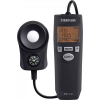
Intended Use
The colour analysis device RGB-2000 is a digital measuring device for optical colour determination and objective quality control. The measuring device is equipped with an external measuring sensor with 45^/0^ colour measuring geometry and integrated LED illumination unit. The colour measuring device serves mainly to measure nonluminous materials like textiles, paper, leather, colour prints, etc. The integrated illumination unit can be switched off and also used for comparison measuring of self-illuminating surfaces like CRT picture tubes, LCD monitors or cold illuminants (e.g. LEDs). The colour space can be displayed in RGB values from 0 - 1023 or HSL values from 0 - 1000.
Via the relative function, it is possible to perform a fast comparison measurement of references and samples. An RS-232 interface allows the further processing of the measuring data with an optional data cable.
A 9 V block battery (type 1604A) is required for operation. Operation with a power pack unit is also possible.
Measurements must not be carried out under unfavourable ambient conditions.
Unfavourable ambient conditions are:
- Wetness or high air humidity
- Dust and flammable gases, vapours or solvents
- Hot illumination sources.
Any use other than described above is not allowed and can damage the product.
No part of the product may be modified or rebuilt!
Observe the safety instructions under all circumstances!
Safety instructions

Please read all the instructions before using this device, they include important information on its correct operation.
The warranty will be void for damage arising from non-compliance with these operating instructions. Liability for any and all consequential damage is excluded!
Nor do we assume liability for damage to property or personal injury caused by improper use or the failure to observe the safety instructions! The warranty is voided in these cases.
This device left the manufacture's factory in a safe and perfect condition.
We kindly request that you as a user observe the safety instructions and warnings contained in this operating manual to preserve this condition and to ensure safe operation! Please pay attention to the following symbols:

An exclamation mark in a triangle indicates important information in these operating instructions which are to be followed strictly.

This product has been CE-tested and meets the necessary European guidelines.

The “hand” symbol indicates special information and advice on operation of the device.
The unauthorized conversion and/or modification of the product is inadmissible for reasons of safety and approval (CE).
Measuring instruments and accessories are not toys and have no place in the hands of children.
On industrial sites the accident prevention regulations of the association of the industrial workers' society for electrical equipment and utilities must be followed.
In schools, training centres, computer and self-help workshops, handling of measuring instruments must be supervised by trained personnel in a responsible manner.
Do not switch the measuring instrument on immediately after it has been taken from a cold to a warm environment. The condensation that forms might destroy your device. Allow the device to reach room temperature before switching it on.
Do not leave packaging material laying around carelessly. These may become dangerous playing material for children.
You should also heed the safety instructions in each chapter of these instructions.
Contents
Colour Analysis Device RGB-2000
External measuring sensor
Calibration card white
Plastic case
Operating instructions
Operating elements
(see fold-out page)
1 button RGB/HSL switching
2 „CAL“ calibration button
3 „POWER“ switch to turn the device on/off
4 „TEST“ measuring button (identical with (16))
5 LCD display
6 Measuring connection for external sensor (17)
7 "Function" button
8 „REL“ button for comparison measurements
9 „LIGHT ON/OFF“ button for measuring light
10 Tripod socket
11 RS232 interface
12 Power pack connection socket
13 Mounting bracket
14 Battery compartment on the rear
15 Measuring opening with 45° LED illumination
16 Measuring button (identical with (4))
17 Sensor connection plug
Display symbols
R Colour value for red
G Colour value for green
B Colour value for blue
Hue Measuring value for the colour hue
Sat Measuring value for the colour saturation
Lum Measuring value for the luminance

Battery replacement symbol; please replace the batteries immediately to avoid measuring errors!
Mesu Measuring in progress. The sensor may not be moved or lifted.
CAL RGB calibration in progress. The sensor may not be moved or lifted.
RS232 Interface is active, data transfer in progress.
Button functions
POWER Power switch; to switch the unit on and off
TEST A push of this button starts measuring. You do not have to keep this button depressed.
Function Function button, which enables white calibration in connection with the „CAL“ button
CAL Calibration button, which enables white calibration in connection with the „Function“ button
REL Button for simple comparison measurement (shows the difference between original and sample)
RGB/HSL Button for switching between RGB and HSL measuring mode
LIGHT Button for turning the integrated sensor illumination on/off
Initial operation
Inserting the batteries
Before the initial operation of this meter, you must first install a new 9V block (alkaline) battery. A power pack unit can be used optionally. Battery installation and power pack operation are described in the „Maintenance and cleaning“ section.
Connecting the measuring sensor
Connect the round plug of the sensor (17) with the socket „PROBE INPUT“ (6) on the measuring device. The plug is protected against wrong polarity and only fits into the socket in the right direction. Observe the arrow marking on the plug. This marking points towards the back of the device. Make sure that the plug is firmly inserted otherwise inaccurate measurements will be made.
Setting up the measuring device
For better reading, the measuring device can be set up using the bracket on the rear (13).
The device can be mounted on a tripod using the tripod socket (10)
Automatic cutoff function
To save on the unnecessary usage of battery power, an automatic switch-off function has been built-in. The device is automatically switched off if no button has been pressed over a period of about 3 minutes. You can switch the device back on with the „Power“ button (3).
Carrying out a measurement

Measurement on hot surfaces or light sources is not admissible.
Never stare directly into a bright light source. This could cause damage to your eyes
Measuring non-self illuminating objects
Non-self illuminating objects are textiles, paper, colour prints, leather, etc. These materials must be illuminated with a defined light source. This light source is located in the sensor head at an angle of 45^ to the measuring surface.
Proceed as follows for RGB measurement:
- Connect the sensor to the measuring device and turn the device on via the „POWER“ button.
- The measuring device signals this with a beep. Wait until the „Mesu“ icon goes off on the display. After activation, the measuring device is always in RGB mode.
- Press the measuring button (4 or 16) and check the activated sensor illumination. If this is not lit, turn the illumination in the sensor head on via the button „LIGHT ON/OFF“ (9).
- Place the sensor head (15) flat onto the object to be measured. The sensor may not be moved or lifted during measuring.
- Briefly press the measuring button (4 or 16) once. Measuring takes place automatically, which is signalled with a beep. The display indicates „Mesu“.
- After measuring, turn the device off via the „POWER“ button.
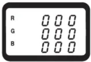
text_image
R G B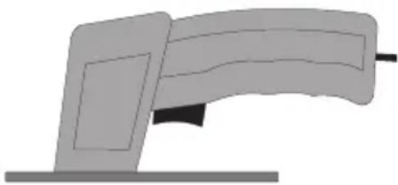
natural_image
Simple illustration of a computer monitor with a scroll, no text or symbols present
The measuring button (4 or 16) must only be pressed briefly. Measuring takes place automatically until the measuring values were determined. The current measurement is indicated on the display with the „Mesu“ icon.
Proceed as follows for HSL measurement:
- Connect the measuring device as described in the section „RGB measuring“ and turn it on.
- To switch to HSL mode, press the button „RGB/HSL“. The display switches to this mode. Another press returns the device to RGB mode.
- Briefly press the measuring button (4 or 16) once. Measuring takes place automatically, which is signalled with a beep. The display indicates „Mesu“.
- After measuring, turn the device off via the „POWER“ button.
text_image
R G B
The human eye can differentiate between more colour shades than can be displayed in the RGB colour space. The HSL colour space therefore corresponds better to the perception of the eye.
„Hue“ differs the colours from each other and you can tell the colour by its value.
„Saturation“ shows how much colour is applied and how high the colour intensity is.
„Luminance“ (brightness/contrast) shows how radiant or intense the colour is.
Measuring self-illuminating objects
Self-illuminating objects are illuminated by a separate, "cold" light source. These objects are e.g. CRT tubes, LCD/TFT monitors, LED illumination, etc. Hot light sources like common light bulbs and halogen spotlights may not be measured.

The measuring device is mainly intended for non-self illuminating objects. Due to the different light sources, the measuring values are not specified in this mode. With self-illuminating objects, the measuring device can only be applied for comparative measurement.
Proceed as follows for the measurement:
- Connect the sensor to the measuring device and turn the device on via the „POWER“ button.
- The measuring device signals this with a beep. Wait until the „Mesu“ icon goes off on the display. After activation, the measuring device is always in RGB mode with activated sensor illumination.
- Switch the illumination function off by pressing the button „LIGHT ON/OFF“ once. A beep confirms your selection.
- Press the measuring button (4 or 16) and check the inactivated sensor illumination. If this is lit, turn the illumination in the sensor head off via the button „LIGHT ON/OFF“ (9).
- Place the sensor head (15) flat onto the object to be measured. The sensor may not be moved or lifted during measuring.
- Briefly press the measuring button (4 or 16) once. Measuring takes place automatically, which is signalled with a beep. The display indicates „Mesu“.
- To switch to HSL mode, press the button „RGB/HSL“. The display switches to this mode. Another press returns the device to RGB mode.
- After measuring, turn the device off via the „POWER“ button.
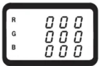
REL comparative measurement
Via the REL function, you can perform a simple comparative measuring operation from a reference surface to a sample surface. Deviating values can be easily detected as „+/0/“ value.
Please proceed as follows to activate this function:
- Perform normal colour measurement on the reference object as described for RGB or HSL measuring.
- Once the measuring value is displayed, press the button „REL“ (8). The displayed values are saved as reference. The display blinks and shows „0 0 0“.
- Place the sensor head on the sample surface and press the measuring button once. The comparison measurement is in progress and shows the difference value after a brief measuring period.
- Deactivate the REL function by once again pressing the „REL“ button (8).
Performing the RGB calibration.
To ensure the accuracy of each measuring operation, the measuring device should be regularly calibrated using the enclosed calibration card.

Calibration is only possible in RGB mode and only with non-illuminating surfaces. The sensor illumination must be activated.
Proceed as follows for calibration:
- Connect the sensor to the measuring device and turn it on.
- Press the measuring button (4 or 16) and check the activated sensor illumination. If this is not lit, turn the illumination in the sensor head on via the button „LIGHT ON/OFF“ (9).
- Open the envelope with the white calibration card and place the sensor head (15) in the center of the white calibration circle. The sensor head must be plane.
- Press the two buttons „Function“ (7) and „CAL“ (2) simultaneously. The calibration procedure starts and the display shows the following:
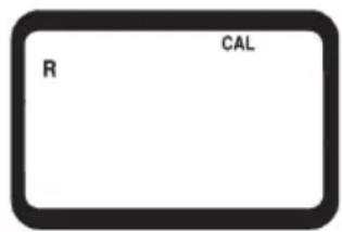
text_image
R CALThe start screen appears on the display for approx. 30 seconds. The sensor may not be moved or lifted during the entire calibration procedure.
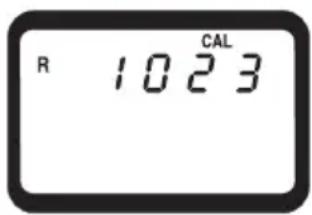
text_image
R 1023 CALAfter this time, the first calibration value appears on the display.
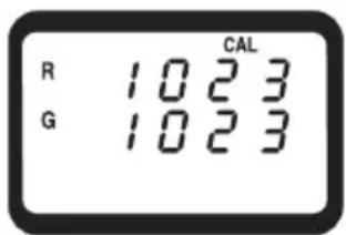
text_image
R 1023 G 1023 CALThe second calibration value appears after approx. 10 seconds.
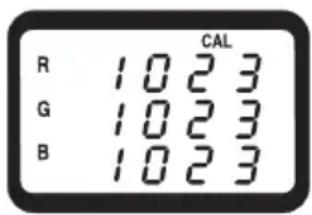
text_image
CAL R 1023 G 1023 B 1023Finally, the third calibration value is displayed after another 10 seconds. The end of the calibration procedure is signalled by three beeps. The CAL symbol disappears after this procedure. Now the measuring device is ready for further measuring operations.
RS232 interface
The measuring device is fitted with a serial interface (11) for exchanging data with a computer. This can be found on the right hand side under a cover. Open the cover with a pointed object. The interface is in the form of a 3.5mm jack plug socket and requires a compatible data cable, which is an optional extra.

You can order the matching interface cable using the following order numbers: Order no.: 122156 RS232 interface cable with jack plug and 9-pole D-USB plug Order no.: 122703 USB interface cable with jack plug and USB plug
The data cable has the following components:
| Jack plug 3.5 mm mono 9-pole | D-SUB socket for PC |
| Center contact Pin 4 | |
| External contact Pin 2 | |
| A 2.2 KOhm is required between pin 2 and pin 5. |
The serial data signal is made up of 16 Bits in the following order:
Each data bit has the following function:
| D0 End signal | |
| D1 to D8 Measuring valueD1 = smallest digit (LSD), D8 = largest digit (MSD).If 1234 is displayed, the bit rate is: „00001234“ | |
| D9 Decimal point (DP) at the corresponding spot from right to left;0= no DP; 1=1DP; 2=2DP; 3=3DP | |
| D10 Polarity; 0 = positive, 1 = negative | |
| D11+D12 Measuring value on the display; R = 70 / G = 71 / B = 72 / H = 42 / S = 73 / L = 99 | |
| D13 Data bit when sending the colour value: Red = 1 / Green = 2 / Blue = 3 / Hue = 4 / Sat = 5 / Lum = 6 | |
| D14 4 | |
| D15 Start bit = 02 | |
The RS232 data format is: 9600, N, 8, 1
Maintenance and cleaning
The colour analysis device RGB-2000 is maintenance-free apart from replacing the batteries and cleaning it once in a while. Use a clean, lint-free, antistatic and dry cloth to clean the device. Do not use any abrasive or chemical agents or detergents containing solvents.
Battery replacement
If the battery symbol appears on the display, the battery has to be replaced as soon as possible to prevent wrong measuring results.
Proceed as follows to replace the batteries:
- Switch off the measuring instrument.
- Loosen the battery compartment screw on the back off the unit, and slide the lid off in the direction of the arrow.
- Replace the flat batteries with new alkaline batteries of the same type (e.g. 1604A).
- Close the casing again carefully by proceeding in reverse order.

Do not leave flat batteries in the device. Even batteries protected against leaking can corrode and thus release chemicals which may be detrimental to your health or destroy the battery compartment.
Batteries may not be charged, shortened or thrown into fire. Batteries may not be recharged. Danger of explosion!
Leaking or damaged batteries/accumulators can cause burning if they come into contact with the skin. Therefore, use suitable protective gloves.
Operation with a power pack unit
Optionally, the measuring device can also be operated with a suitable power pack unit. The power pack socket (12) is located on the right side of the casing beneath a cover (DC IN). Open the cover with a pointed object. The matching plug has the following technical specifications:
Dimensions outside 5.5 mm, inner hole 2.5 mm.
Polarity: Outside minus (-), inside plus (+)
Operating data: Voltage: 9 VDC, current: at least 34 mA

Order a matching battery using the order number 65 25 09. Order the matching power pack unit using the order number 12 26 99.
Disposal
Electronic products are raw material and do not belong in the household waste. When the device has reached the end of its service life, dispose of it in accordance with the current statutory regulations at the communal collection points. Disposal in the domestic waste is not permitted.
Disposal of used batteries/rechargeable batteries

The user is legally obliged (battery regulation) to return used batteries and storage batteries. Do not dispose of used batteries via the household rubbish!
Contaminated batteries/rechargeable batteries are labelled with these symbols to indicate that disposal in domestic waste is forbidden. The symbols for dangerous heavy metals are: Cd = Cadmium, Hg = Mercury, Pb = Lead. You can dispose of your used batteries free of charge at your community's collection point or any place where batteries are sold!
You thus fulfil the legal requirements and make your contribution to protecting the environment!
Troubleshooting
In purchasing this measuring unit, you have acquired a product which has been designed to the state of the art and is operationally reliable.
Nevertheless, problems or faults may occur.
For this reason, the following is a description of how you can eliminate possible malfunctions yourself.

Please always observe the safety instructions!
| Error Possible cause Remedy | ||
| The measuring device Is cannot be turned on. Remove the battery and insert it again | status.(reset). | |
| No correct measuring value is displayed. With non-illuminated objects, the sensor on sensor illumination is not turned on Perform an RGB calibration.Switch on the sensor illumination. | position of the the measuring surface. | |
| Measuring device cannot be operated. (perform a reset). | Undefined system status. Remove the battery and insert it again | |

Any repair work other than that described above must be carried out by an approved specialist. If you have questions concerning use of the measuring device, our technical support service is available at the following telephone number:
Voltcraft, Lindenweg 15, 92242 Hirschau, tel. no. 0180 / 586 582 723 8
Technical data
Display ....3-line LC display
Sensor ....3 colour photo transistors (red/green/blue)
Measuring geometry ....45° illumination angle/0° measuring angle
Spectral range 400 to 700 nm
Integrated light source ....2 white LEDsμ
Measuring range RGB ....per primary colour 0 to 1023
HSL measuring range ....per value 0 to 1,000
Repeatability RGB ....../< 3
Repeatability HSL ....< 0,01
Battery 1x 9V Block battery (006P, MN1604)
Optional power pack ....9 V DC stabilised
Power input ......max. 32 mA
Operating temperature....0 to +50°C
Rel. air humidity ....< 80%, non-condensing
Weight (without battery)......ca. 440 g
Dimensions (LxWxH mm): 203 x 76 x 38 (measuring device)
160 x 92 x 45 (sensor)
Sensor cable length ......ca. 1 m
Definition of repeatability
The repeatability is valid at an ambient temperature of +23^ ± 5K , and a relative humidity of less than 80% , non-condensing. The repeatability is defined as follows: Right after a white calibration, for 10 measurements on the same object within 2 minutes.
F Introduction
Chère cliente, cher client,
natural_image
Simple illustration of a computer monitor with an open screen and scroll (no text or symbols)
Mesure comparative REL
natural_image
Simple illustration of a rolled-up document or scroll with no text or symbols