Loop 10000 - Water pump EHEIM - Free user manual and instructions
Find the device manual for free Loop 10000 EHEIM in PDF.
User questions about Loop 10000 EHEIM
0 question about this device. Answer the ones you know or ask your own.
Ask a new question about this device
Download the instructions for your Water pump in PDF format for free! Find your manual Loop 10000 - EHEIM and take your electronic device back in hand. On this page are published all the documents necessary for the use of your device. Loop 10000 by EHEIM.
USER MANUAL Loop 10000 EHEIM
natural_image
Technical line drawing of two square industrial enclosures with labeled dimensions (5000 and 7000), no text or symbols on the devices themselves.
natural_image
Isometric technical drawing of a rectangular electronic box with internal components and mounting holes, labeled with dimensions 10000 and 15000 (no text or symbols on the diagram itself)de Bedienungsanleitung
en Operating manual
fr Mode d'emploi
it Istruzioni per l'uso
es Manual de instrucciones
pt Manual de instruções
nl Bedieningshandleiding
da Betjeningsvejledning
sv Bruksanvisning
tr İşletim kılavuzunun
pl Instrukcji obsługi
ru Руководство по эксплуатации
A

text_image
LOOP5000 LOOP7000LOOP5000
LOOP7000

text_image
Technical diagram of a mechanical device with numbered components and labeled partsLOOP10000
LOOP15000
B

text_image
LOOP5000 LOOP7000B

text_image
LOOP10000 LOOP15000C
text_image
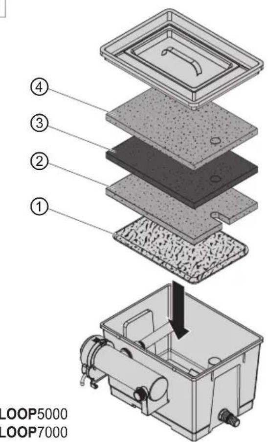
① ② ③ ④ LOOP5000 LOOP7000
text_image
① ② ③ ④ LOOP10000 LOOP15000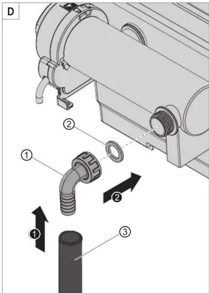
text_image
D ① ② ③
text_image
E 1" 1¼"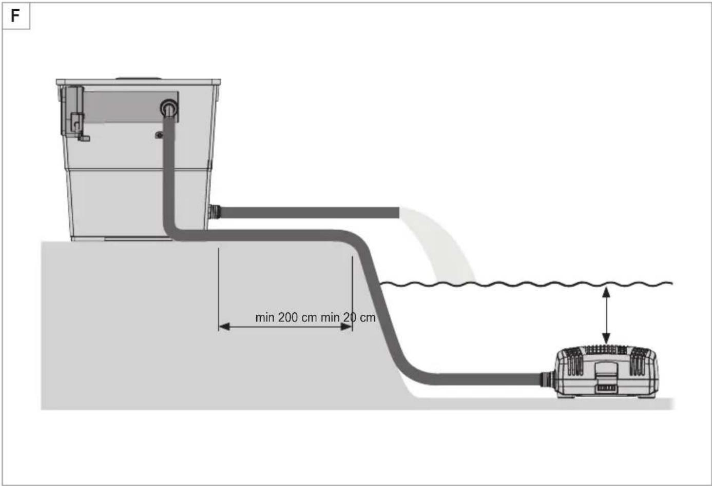
text_image
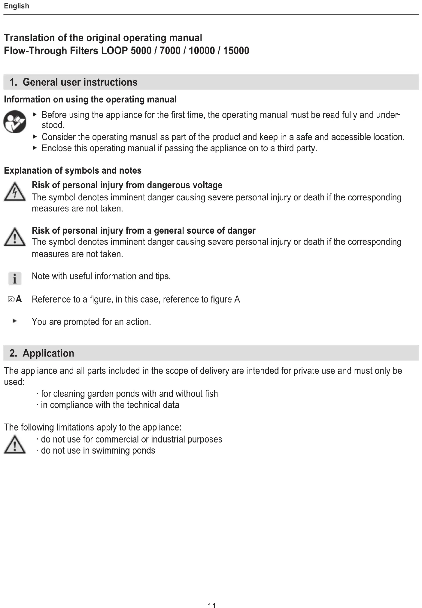
F min 200 cm min 20 cmTranslation of the original operating manual Flow-Through Filters LOOP 5000 / 7000 / 10000 / 15000
1. General user instructions
Information on using the operating manual

Before using the appliance for the first time, the operating manual must be read fully and understood.
- Consider the operating manual as part of the product and keep in a safe and accessible location.
▶ Enclose this operating manual if passing the appliance on to a third party.
Explanation of symbols and notes

Risk of personal injury from dangerous voltage
The symbol denotes imminent danger causing severe personal injury or death if the corresponding measures are not taken.

Risk of personal injury from a general source of danger
The symbol denotes imminent danger causing severe personal injury or death if the corresponding measures are not taken.
i
Note with useful information and tips.
A
Reference to a figure, in this case, reference to figure A
▶
You are prompted for an action.
2. Application
The appliance and all parts included in the scope of delivery are intended for private use and must only be used:
· for cleaning garden ponds with and without fish
· in compliance with the technical data
The following limitations apply to the appliance:

· do not use for commercial or industrial purposes
· do not use in swimming ponds
3. Safety instructions
Risks for persons and property can arise from this appliance if the appliance is improperly used or not used as intended or if the safety instructions are not heeded.
- Do not let the appliance packaging get into the hands of children as hazards can arise (danger of suffocation!).
- This appliance can be used by children from the age of 8 and by persons with reduced physical, sensory or mental capabilities or lack of experience and/or knowledge if they are supervised and have been instructed in the safe use of the appliance and have understood the resulting dangers. Children must not play with the appliance. Cleaning and user maintenance must not be carried out by children unless they are supervised.
Electrical safety

- The device's safety distance from the water must be at least 2 m.
Safe operation

- The appliance is operated using the pump and UVC clarifier supplied. Heed the operating manual, especially the chapters concerning the safety, commissioning, operating and maintenance of these components!
- Before use, carry out a visual inspection to ensure that the appliance is undamaged.
- Do not use the appliance if it is not working properly or is damaged.
- Only carry out the work described in these instructions.
- Never make technical modifications to the appliance.
- Only use original spare parts and accessories for the appliance.
4. Commissioning
Install the overflow pipe (☒A)
LOOP5000/7000
- Insert the outlet spigot ③ through the opening in the filter housing.
- Slip the seal ② onto the outlet spigot from the inside.
- Screw the outlet spigot onto the overflow pipe ①.
LOOP10000/15000
- Insert the outlet spigot ③ through the opening in the filter housing.
- Slip the seal ② onto the outlet spigot from the inside.
- Screw the outlet spigot onto the overflow pipe ①.
- Install the second overflow pipe in identical order.
Install UVC clarifier (☒B)
LOOP5000/7000
- Slip the sealing washer ② onto the thread of the UVC clarifier ①.
- Insert the UVC purification unit through the opening in the filter housing.
- Screw the intermediate piece ③ onto the UVC clarifier from the inside.
- Screw the sprinkler pipe ④ onto the intermediate piece.
- Insert the screw ⑤ with the washer ⑥ and the O-ring ⑦ through the hole in the mounting bracket of the UVC clarifier from the inside.
- Tighten the UVC clarifier using the screw ⑨ and the washer⑧.
LOOP10000/15000
- Slip the sealing washer ② onto the thread of the UVC clarifier ①.
- Insert the UVC purification unit through the opening in the filter housing.
- Screw the T-intermediate piece ③ onto the UVC clarifier from the inside.
- Screw the two sprinkler pipes ④ onto the T-intermediate piece.
- Insert the screw ⑤ with the washer ⑥ and the O-ring ⑦ through the hole in the mounting bracket of the UVC clarifier from the inside.
- Tighten the UVC clarifier using the screw ⑨ and the washer ⑧.
Inserting the filter (☒C)
LOOP5000/7000
-
Fill the included net with the EHEIM FILTERBIO granulate (biological filter granulate).
-
Insert the filter in the filter housing in the following order:
① Net with EHEIM FILTERBIO granulate Attention: The net must lie flat on the housing base
② Blue filter foam, fine
③ Active carbon fleece
④ Blue filter foam, coarse
LOOP10000/15000
-
Fill the EHEIM FILTERMEC granulate (mechanical filter granulate) ① loosely in the filter housing.
-
Insert the filter in the filter housing in the following order:
② Blue filter foam, fine
③ Active carbon fleece
④ Blue filter foam, coarse
Installing the pump connection (☒D)
- Connect the spiral hose ③ of the pump to the connecting piece ①.
- Insert the sealing washer ② into the connecting piece.
- Screw the connecting piece onto the UVC clarifier with the union nut.
Connect the outlet hose (☒E)
- Use a saw to shorten the outlet spigot to the diameter of your hose.
- Connect your hose to the outlet spigot.

We recommend fastening the hoses with hose clamps
5. Operation

Attention! Electrocution!
- The device's safety distance from the water must be at least 2 m.

Caution!
- Heed the operating manual for the UVC clarifier and the pump, especially the chapters on safety, commissioning and operation.
- Place the filter on the pond bank (☒F).
- Place the pump on a solid surface as horizontal as possible in the pond so that the filter housing of the pump is covered by at least 20 cm of water. Pay attention to the maximum pond depth (see Technical data).
Switching on the pump and UVC clarifier
- Insert the respective mains plug into the mains socket.
Attention: The pump starts immediately!
Switching off the pump and UVC clarifier
- Remove the respective mains plug from the mains socket.
6. Maintenance

Attention! Electrocution!
▶ Before all maintenance work, disconnect the mains plugs of the pump and the UVC clarifier.

Caution!
- Heed the operating manual for the UVC clarifier and the pump, especially the chapters on safety and maintenance.

Caution! Material damage.
- Do not use hard objects or aggressive cleaning agents for cleaning.

The following sections describe maintenance work necessary for optimum and fault-free operation. Regular maintenance prolongs the service life and assures functionality of the filter over a long period.
Cleaning the filter
The inside of the filter must be checked approximately every 4 weeks and cleaned according to the degree of soiling. To do so, proceed as follows:
- Remove the mains plugs of the pump and the UVC clarifier.
- Open the filter housing.
- Remove the filter from the housing (☒C).
- Remove the EHEIM FILTERBIO or EHEIM FILTERMECH granulate from the filter housing.
- Clean the filter and the granulate under cold, running water.
- Clean the inside of the filter housing with a water jet.
- Install the filter again in reverse order (☒C).

Recommended maintenance
The service life of the active carbon fleece is limited to approx. 4 weeks. After this, the fleece releases the harmful substances back into the water. The fleece can simply be removed or replaced by a new fleece if necessary.
7. Clearing faults

Attention! Electrocution!
▶ Before clearing faults, remove the mains plug.
Faults Possible cause Remedy
| Filter capacity decreases | Filter installation not correct | ▶ Check whether the filter is instal-led in the correct order. |
| Filter is soiled ▶ Clean the filter | ||
| Pump is soiled ▶ Clean the filter housing of the pump (see pump operating manual) | ||
For other faults, please contact EHEIM Service.
8. Decommissioning
Storing and overwintering

- Clean the appliance
- Store the appliance in a frost-proof place.
Disposal

When disposing of the appliance, heed the respective statutory regulations. The appliance may no longer be disposed of with the municipal or household waste. The appliance will be accepted free of charge at municipal collection points or recycling centres. The product packaging is made up of recyclable materials. Dispose of them in an environmentally responsible manner and take them for recycling.
- Technical data
| Type 5000 7000 10000 15000 | ||||
| Pump | PLAY1500 | FLOW2500 | FLOW3500 | FLOW5000 |
| UVC clarifiers | CLEARUVC-7 | CLEARUVC-9 | CLEARUVC-11 | CLEARUVC-11 |
| Dimensions (L×W×H) 400×315×263 mm 400×315×388 mm 603×398×368 mm | ||||
| Water outlet 1" – 11⁄4" | ||||
| Media temperature | 4°C – 35°C | |||

The technical data of the pump and the UVC clarifier are found in the associated operating manuals.
10. Spare parts
See page 77.
| Item | 5000 | 7000 | 10000 | 15000 |
| 1 | 2516101 | 2516101 | 2517851 | 2517851 |
| 2 | 2629210 | 2629210 | 2629310 | 2629310 |
| 3 | 2629010 | 2629010 | 2629110 | 2629110 |
| 4 | 2629410 | 2629410 | 2629510 | 2629510 |
text_image
Exploded view diagram of a mechanical assembly with numbered components for identificationLOOP5000
LOOP7000
H

text_image
Technical diagram showing cross-section of a mechanical assembly with numbered components and exploded view of internal components.LOOP10000
LOOP15000
Reproduction or copying – even parts thereof – only with the express permission of the producer.