
MF7200D - Sewing machine JUKI - Free user manual and instructions
Find the device manual for free MF7200D JUKI in PDF.

| Product Type | High-speed compact overlock sewing machine with semi-dry head and cylindrical bed |
| Brand | Juki |
| Model | MF-7200D |
| Dimensions (H x W x D) | 450 x 444 x 285 mm |
| Weight | 42 kg |
| Maximum sewing speed | 4,000 sti/min (intermittent operation) |
| Needle | UY128GAS No. 9 to 12 (standard No. 10) |
| Stitch length | 1.4 to 3.2 mm (adjustable up to 4.2 mm) |
| Differential feed ratio | 1:0.8 to 1:1.8 (with micro-adjustment) |
| Needle gauge | 3 needles: 5.6 mm and 6.4 mm; 2 needles: 3.2 mm, 4.0 mm and 4.8 mm |
| Presser foot lift height | 6 mm (without top cover) / 5 mm (with top cover); built-in micro-lifter |
| Lubrication system | Forced lubrication by gear pump; oil tank 600 to 900 cm³ (JUKI MACHINE OIL 18) |
| Power supply | Three-phase clutch motor 400 W (1/2 HP); voltage and frequency according to installation |
| Main functions | Hemming and overcasting for knits and mesh fabrics; overlock stitch (ISO 406, 407, 602, 605) |
| Sound level | Sound pressure 80.5 dB(A); sound power 86.0 dB(A) at 4000 sti/min |
| Safety | Finger guard, eye guard, belt cover, needle bar cover, emergency stop |
| Maintenance and cleaning | Regular cleaning of feed dogs and needle plate; oil renewal every 6 months; oil filter check |
| Spare parts and repairability | Original Juki parts recommended; maintenance by qualified technician |
Frequently Asked Questions - MF7200D JUKI
User questions about MF7200D JUKI
0 question about this device. Answer the ones you know or ask your own.
Ask a new question about this device
Download the instructions for your Sewing machine in PDF format for free! Find your manual MF7200D - JUKI and take your electronic device back in hand. On this page are published all the documents necessary for the use of your device. MF7200D by JUKI.
USER MANUAL MF7200D JUKI
TO ENSURE SAFE USE OF YOUR SEWING MACHINE
For the sewing machine, automatic machine and ancillary devices (hereinafter collectively referred to as "machine"), it is inevitable to conduct sewing work near moving parts of the machine. This means that there is always a possibility of unintentionally coming in contact with the moving parts. Operators who actually operate the machine and maintenance personnel who are involved in maintenance and repair of the machine are strongly recommended to carefully read to fully understand the following SAFETY PRECAUTIONS before using/maintaining the machine. The content of the SAFETY PRECAUTIONS includes items which are not contained in the specifications of your product.
The risk indications are classified into the following three different categories to help understand the meaning of the labels. Be sure to fully understand the following description and strictly observe the instructions.
(I) Explanation of risk levels
| DANGER :This indication is given where there is an immediate danger of death or serous injury if the person in charge or any third party mishandles the machine or does not avoid the dangerous situation when operating or maintaining the machine. |
| WARNING :This indication is given where there is a potentiality for death or serious injury if the person in charge or any third party mishandles the machine or does not avoid the dangerous situation when operating or maintaining the machine. |
| CAUTION :This indication is given where there is a danger of medium to minor injury if the person in charge or any third party mishandles the machine or does not avoid the dangerous situation when operating or maintaining the machine. |
| Items requiring special attention. |
(II) Explanation of pictorial warning indications and warning labels
| Pictorial warning indication | There is a risk of injury if contacting a moving section. | Pictorial warning indication | Be aware that holding the sewing machine during operation can hurt your hands. | ||
| There is a risk of electrical shock if contacting a high-voltage section. | There is a risk of entanglement in the belt resulting in injury. | ||||
| There is a risk of a burn if contacting a high-temperature section. | There is a risk of injury if you touch the button carrier. | ||||
| Be aware that eye deficiency can be caused by looking directly at the laser beam. | Indication label | The correct direction is indicated. | |||
| There is a risk of contact between your head and the sewing machine. | Connection of a earth cable is indicated. |
| Warning label | 1→2→ | 1 2→3 | ←3→ | 1 2→3→4 |
| 1·There is the possibility that slight to serious injury or death may be caused. ·There is the possibility that injury may be caused by touching moving part. 2·To perform sewing work with safety guard. ·To perform sewing work with safety cover. ·To perform sewing work with safety protection device. 3·Be sure to turn the power OFF before carrying out "machine-head threading", "needle changing", "bobbin changing" or "oiling and cleaning". | 1 2→3→4 | |||
| Electrical-shock danger label | 危险 | DANGER | ||
| 高电压部分に触い、大千伏をむるごgether。電源を切て、5分以上たてからかがはしだと。 | Hazardous voltage will cause injury. Turn off main switch and unplug power cord and wait at least 5 minutes before opening this cover. | |||

DANGER
- When it is necessary to open the control box containing electrical parts, be sure to turn the power off and wait for five minutes or more before opening the cover in order to prevent accident leading to electrical shock.

CAUTION
Basic precaution
- Be sure to read the instruction manual and other explanatory documents supplied with accessories of the machine before using the machine. Carefully keep the instruction manual and the explanatory documents at hand for quick reference.
- The content of this section includes items which are not contained in the specifications of your product.
- Be sure to wear safety goggles to protect against accident caused by needle breakage.
- Those who use a heart pacer have to use the machine after consultation with a medical specialist.
Safety devices and warning labels
- Be sure to operate the machine after verifying that safety device(s) is correctly installed in place and works normally in order to prevent accident caused by lack of the device(s).
- If any of the safety devices is removed, be sure to replace it and verify that it works normally in order to prevent accident that can result in personal injury or death.
- Be sure to keep the warning labels adhered on the machine clearly visible in order to prevent accident that can result in personal injury or death. If any of the labels has stained or come unstuck, be sure to change it with a new one.
Application and modification
- Never use the machine for any application other than its intended one and in any manner other than that prescribed in the instruction manual in order to prevent accident that can result in personal injury or death. JUKI assumes no responsibility for damages or personal injury or death resulting from the use of the machine for any application other than the intended one.
- Never modify and alter the machine in order to prevent accident that can result in personal injury or death. JUKI assumes no responsibility for damages or personal injury or death resulting from the machine which has been modified or altered.
Education and training
- In order to prevent accident resulting from unfamiliarity with the machine, the machine has to be used only by the operator who has been trained/educated by the employer with respect to the machine operation and how to operate the machine with safety to acquire adequate knowledge and operation skill. To ensure the above, the employer has to establish an education/training plan for the operators and educate/train them beforehand.
Items for which the power to the machine has to be turned off
Turning the power off: Turning the power switch off, then removing the power plug from the outlet. This applies to the following.
- Be sure to immediately turn the power off if any abnormality or failure is found or in the case of power failure in order to protect against accident that can result in personal injury or death.
- To protect against accident resulting from abrupt start of the machine, be sure to carry out the following operations after turning the power off. For the machine incorporating a clutch motor, in particular, be sure to carry out the following operations after turning the power off and verifying that the machine stops completely.
2-1. For example, threading the parts such as the needle, looper, spreader etc. which have to be threaded, or changing the bobbin.
2-2. For example, changing or adjusting all component parts of the machine.
2-3. For example, when inspecting, repairing or cleaning the machine or leaving the machine. - Be sure to remove the power plug by holding the plug section instead of the cord section in order to prevent electrical-shock, earth-leakage or fire accident.
- Be sure to turn the power off whenever the machine is left unattended between works.
- Be sure to turn the power off in the case of power failure in order to prevent accident resulting of breakage of electrical components.
PRECAUTIONS TO BE TAKEN IN VARIOUS OPERATION STAGES
Transportation
- Be sure to lift and move the machine in a safe manner taking the machine weight in consideration. Refer to the text of the instruction manual for the mass of the machine.
- Be sure to take sufficient safety measures to prevent falling or dropping before lifting or moving the machine in order to protect against accident that can result in personal injury or death.
- Once the machine has been unpacked, never re-pack it for transportation to protect the machine against breakage resulting from unexpected accident or dropping.
Unpacking
- Be sure to unpack the machine in the prescribed order in order to prevent accident that can result in personal injury or death. In the case the machine is crated, in particular, be sure to carefully check nails. The nails have to be removed.
- Be sure to check the machine for the position of its center of gravity and take it out from the package carefully in order to prevent accident that can result in personal injury or death.
Installation
(I) Table and table stand
- Be sure to use JUKI genuine table and table stand in order to prevent accident that can result in personal injury or death. If it is inevitable to use a table and table stand which are not JUKI genuine ones, select the table and table stand which are able to support the machine weight and reaction force during operation.
- If casters are fitted to the table stand, be sure to use the casters with a locking mechanism and lock them to secure the machine during the operation, maintenance, inspection and repair in order to prevent accident that can result in personal injury or death.
(II) Cable and wiring
- Be sure to prevent an extra force from being applied to the cable during the use in order to prevent electrical-shock, earth-leakage or fire accident. In addition, if it is necessary to cable near the operating section such as the V-belt, be sure to provide a space of 30mm or more between the operating section and the cable.
- Be sure to avoid starburst connection in order to prevent electrical-shock, earth-leakage or fire accident.
- Be sure to securely connect the connectors in order to prevent electrical-shock, earth-leakage or fire accident. In addition, be sure to remove the connector while holding its connector section.
(III) Grounding
- Be sure to have an electrical expert install an appropriate power plug in order to prevent accident caused by earth-leakage or dielectric strength voltage fault. In addition, be sure to connect the power plug to the grounded outlet without exceptions.
- Be sure to ground the earth cable in order to prevent accident caused by earth leakage.
(IV) Motor
- Be sure to use the specified rated motor (JUKI genuine product) in order to prevent accident caused by burnout.
- If a commercially available clutch motor is used with the machine, be sure to select one with an entanglement preventive pulley cover in order to protect against being entangled by the V-belt.
Before operation
- Be sure to make sure that the connectors and cables are free from damage, dropout and looseness before turning the power on in order to prevent accident resulting in personal injury or death.
- Never put your hand into the moving sections of the machine in order to prevent accident that can result in personal injury or death.
In addition, check to be sure that the direction of rotation of the pulley agrees with the arrow shown on pulley.
3. If the table stand with casters is used, be sure to secure the table stand by locking the casters or with adjusters, if provided, in order to protect against accident caused by abrupt start of the machine.
During operation
- Be sure not to put your fingers, hair or clothing close to the moving sections such as the handwheel, hand pulley and motor or place something near those sections while the machine is in operation in order to prevent accident caused by entanglement that can result in personal injury or death.
- Be sure not to place your fingers near the surround area of the needle or inside the thread take-up lever cover when turning the power on or while the machine is in operation in order to prevent accident that can result in personal injury or death.
- The machine runs at a high speed. Never bring your hands near the moving sections such as looper, spreader, needle bar, hook and cloth trimming knife during operation in order to protect your hands against injury. In addition, be sure to turn the power off and check to be sure that the machine completely stops before changing the thread.
-
Be careful not to allow your fingers or any other parts of your body to be caught between the machine and table when removing the machine from or replacing it on the table in order to prevent accident that can result in personal injury or death.
-
Be sure to turn the power off and check to be sure that the machine and motor completely stop before removing the belt cover and V-belt in order to prevent accident caused by abrupt start of the machine or motor.
- If a servomotor is used with the machine, the motor does not produce noise while the machine is at rest. Be sure not to forget to turn the power off in order to prevent accident caused by abrupt start of the motor.
- Never use the machine with the cooling opening of the motor power box shielded in order to prevent fire accident by overheat.
Lubrication
- Be sure to use JUKI genuine oil and JUKI genuine grease to the parts to be lubricated.
- If the oil adheres on your eye or body, be sure to immediately wash it off in order to prevent inflammation or irritation.
- If the oil is swallowed unintentionally, be sure to immediately consult a medical doctor in order to prevent diarrhea or vomiting.
Maintenance
- In prevention of accident caused by unfamiliarity with the machine, repair and adjustment has to be carried out by a service technician who is thoroughly familiar with the machine within the scope defined in the instruction manual. Be sure to use JUKI genuine parts when replacing any of the machine parts. JUKI assumes no responsibility for any accident caused by improper repair or adjustment or the use of any part other than JUKI genuine one.
- In prevention of accident caused by unfamiliarity with the machine or electrical-shock accident, be sure to ask an electrical technician of your company or JUKI or distributor in your area for repair and maintenance (including wiring) of electrical components.
- When carrying out repair or maintenance of the machine which uses air-driven parts such as an air cylinder, be sure to remove the air supply pipe to expel air remaining in the machine beforehand, in order to prevent accident caused by abrupt start of the air-driven parts.
- Be sure to check that screws and nuts are free from looseness after completion of repair, adjustment and part replacement.
- Be sure to periodically clean up the machine during its duration of use. Be sure to turn the power off and verify that the machine and motor stop completely before cleaning the machine in order to prevent accident caused by abrupt start of the machine or motor.
- Be sure to turn the power off and verify that the machine and motor stop completely before carrying out maintenance, inspection or repair of the machine. (For the machine with a clutch motor, the motor will keep running for a while by inertia even after turning the power off. So, be careful.)
- If the machine cannot be normally operated after repair or adjustment, immediately stop operation and contact JUKI or the distributor in your area for repair in order to prevent accident that can result in personal injury or death.
- If the fuse has blown, be sure to turn the power off and eliminate the cause of blowing of the fuse and replace the blown fuse with a new one in order to prevent accident that can result in personal injury or death.
- Be sure to periodically clean up the air vent of the fan and inspect the area around the wiring in order to prevent fire accident of the motor.
Operating environment
- Be sure to use the machine under the environment which is not affected by strong noise source (electromagnetic waves) such as a high-frequency welder in order to prevent accident caused by malfunction of the machine.
- Never operate the machine in any place where the voltage fluctuates by more than "rated voltage ± 10% " in order to prevent accident caused by malfunction of the machine.
- Be sure to verify that the air-driven device such as an air cylinder operates at the specified air pressure before using it in order to prevent accident caused by malfunction of the machine.
- To use the machine with safety, be sure to use it under the environment which satisfies the following conditions:
Ambient temperature during operation 5^ to 35^
Relative humidity during operation 35% to 85%
- Dew condensation can occur if bringing the machine suddenly from a cold environment to a warm one. So, be sure to turn the power on after having waited for a sufficient period of time until there is no sign of water droplet in order to prevent accident caused by breakage or malfunction of the electrical components.
- Be sure to stop operation when lightning flashes for the sake of safety and remove the power plug in order to prevent accident caused by breakage or malfunction of the electrical components.
- Depending on the radio wave signal condition, the machine may generate noise in the TV or radio. If this occurs, use the TV or radio with kept well away from the machine.
- In order to ensure the work environment, local laws and regulations in the country where the sewing machine is installed shall be followed. In the case the noise control is necessary, an ear protector or other protective gear should be worn according to the applicable laws and regulations.
- Disposal of products and packages and treatment of used lubricating oil should be carried out properly according to the relevant laws of the country in which the sewing machine is used.
FOR SAFE OPERATION


- To prevent accidents caused by electric shock, never open the motor control box cover or touch the components inside the control box while the power switch is ON.
- Never bring your fingers under the needle when the power switch is turned ON or the machine is in operation.
- Never bring your fingers, hair or clothes close to the pulley and needle or place anything on the pulley and under the needle while the machine is in operation.
- Never operate the machine with the safety devices such as belt cover, needle thread take-up cover, finger guard, eye guard cover, etc. removed.
- Be sure to turn OFF the power and perform the work after ascertaining that the sewing machine does not run even when the starting pedal is depressed in case of checking, adjusting, cleaning, threading or replacing the needle of the sewing machine.
- Never operate the sewing machine with the ground wire for the power supply removed so as to ensure safety.
- Be sure to turn OFF the power switch in advance in case of inserting/removing the power plug.
- In time of thunder and lightning, stop your work and disconnect the power plug from the receptacle so as to ensure safety.
- When you move the sewing machine from a cold place directly to a warm place, dew condensation may result. Turn ON the power to the machine after you have confirmed that there is no fear of dew condensation.
- In case of maintenance, inspection, or repair, be sure to turn OFF the power switch and confirm that the sewing machine and the motor have completely stopped before starting the work. (In case of the clutch motor, it continues rotating for a while by the inertia even after turning OFF the power switch. So, be careful.)
- Be careful of handling this product so as not to pour water or oil, shock by dropping, and the like since this product is a precision instrument.
To avoid malfunction and damage of the machine, confirm the following.
- Be sure to fill the oil hole with oil designated by JUKI before use.
- Clean the sewing machine thoroughly before using it for the first time.
- Remove all dust collected on the sewing machine during the transportation.
- Confirm that the voltage and phase are correct.
- Confirm that the power plug is properly connected.
- Never use the sewing machine in the state where the voltage type is different from the designated one.
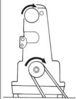
- The direction of rotation of the sewing machine is clockwise as observed from the pulley side. Be careful not to rotate it in reverse direction.
- When operating the sewing machine, turn ON the power switch after properly setting the head on the table.
- For the first month after set-up, use the machine at a reduced sewing speed of 3,500 sti/min or less.
- Operate the pulley after the sewing machine has totally stopped.

CAUTION
In addition, be aware that the safety devices such as the "eye protection cover" and "finger guard" are sometimes omitted in the sketches, illustrations and figures included in the Instruction Manual for the explanation's sake. In the practical use, never remove those safety devices.
DECLARATION OF INCORPORATION OF PARTLY COMPLETED MACHINERY
We hereby declare that the sewing machine (sewing head) described below;
- Must not be put into service until the machinery to which it is incorporated has been declared in conformity with the provisions of the Directive 2006/42/EC, and
- Conforms to the essential requirements of the Directive 2006/42/EC, described in the technical documentation, and
- To be prepared with the above technical documentation compiled in accordance with part B of Annex VII, and
- Also to conform to the RoHS Directive 2011/65/EU
- Relevant information on which should be transmitted in response to a reasoned request by the national authorities, by the electronic method or other according to the request.
Model MF-7200D Series
Description Industrial Sewing Machine
Function make stitches and sew
Applied harmonized standards, in particular:
EN ISO12100, EN ISO10821, EN 50581
Manufacturer :
JUKI CORPORATION
2-11-1, Tsurumaki, Tama-shi, Tokyo, Japan


CONTENTS
I . SPECIFICATIONS. 1
II. CONFIGURATION OF THE MACHINE COMPONENTS 2
Ⅲ. INSTALLATION 3
- Installing the machine head onto the table 3
- Selecting the motor pulley and the belt.. 7
- Installing the motor.. 7
- Setting the belt 7
- Installing the belt cover 8
- Installing the chain 8
- Installing the thread guide 8
IV. LUBRICATION AND OILING 9
- Lubricating oil 9
- Oiling 9
- Replacing the lubricating oil 9
- Silicon oil lubricating unit 10
V. OPERATION 10
- Needle 10
- Attaching the needle 10
- Threading the machine head 11
- Adjusting the stitch length 12
- Adjusting the differential feed ratio 12
- Adjusting the presser foot pressure 13
- Adjusting the thread tension 13
VI. ADJUSTING THE SEWING MACHINE 14
- Adjusting the silicon container thread guide 14
- Adjusting the needle bar thread take-up thread receiver 14
- Adjusting the rocking thread take-up 15
- Adjusting the rocking thread take-up thread receiver 15
- Adjusting the spreader thread guide 15
- Adjusting the looper thread cam thread guide and the looper thread cam 16
- Adjusting the looper thread winding prevention plate 16
- Adjusting the looper 17
-
Adjusting the height of the needle 17
-
Adjusting the rear needle guard 18
-
Relation between the rocking thread take-up timing and the needle thread loop... 18
- Adjusting the height of the feed dog 19
- Installing position of the spreader 19
- Adjusting the spreader thread guide and the needle clamp thread guide 20
- Adjusting the front needle guard 20
- Adjusting the presser foot lift 21
- Adjusting the micro-lifter 21
VII. MAINTENANCE 22
- Cleaning the sewing machine 22
- Replacing the lubricating oil 22
- Inspecting and replacing the oil filter 22
I. SPECIFICATIONS
| Model name Semi-dry head high-speed, small cylinder-bed coverstitch machine | |
| Model MF-7200D series | |
| Stitch type | ISO standard 406, 407, 602, and 605 |
| Example of application Hemming and covering for knits and general knitted fabrics | |
| Max. speed of stitch Max. | 4,000 sti/min (at the time of intermittent operation) |
| Needle gauge | 3-needle ... 5.6 mm and 6.4 mm 2-needle ... 3.2 mm, 4.0 mm and 4.8 mm |
| Differential feed ratio | 1:0.8 to 1:1.8 (stitch length: less than 3.2 mm) Micro-differential feed adjustment mechanism is provided. (Micro-adjustment) |
| Stitch length | 1.4 mm to 3.2 mm (can be adjusted up to 4.2 mm) |
| Needle UY128GAS #9S to #12S (standard #10S) | |
| Needle bar stroke 31mm | |
| Dimensions (Height) 450 x (Width) 444 x (Length) 285 | |
| Weight | 42 kg |
| Lift of presser foot | 6 mm (needle gauge: 5.6 mm without top covering), and 5 mm (with top covering) Micro-lifter mechanism is provided. |
| Feed adjustment method | Main feed ... dial type stitch pitch adjustment method Differential feed ... lever adjustment method (micro-adjustment mechanism is provided.) |
| Looper mechanism Spherical rod drive method | |
| Lubricating system Forced lubrication method by gear pump | |
| Lubricating oil | JUKI MACHINE OIL 18 |
| Oil reservoir capacity Oil gauge lower line: 600 cc to upper line: 900 cc | |
| Installation Top mount type, Semi-submerged type | |
| Noise | - Equivalent continuous emission sound pressure level (LpA) at the workstation: A-weighted value of 80.5 dB; (Includes KpA = 2.5 dB); according to ISO 10821-C.6.2 -ISO 11204 GR2 at 4,000 sti/min. - Sound power level (LwA); A-weighted value of 86.0 dB; (Includes KwA = 2.5 dB); according to ISO 10821-C.6.2 -ISO 3744 GR2 at 4,000 sti/min. |
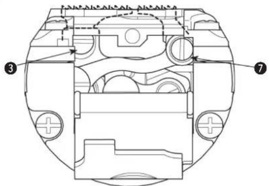
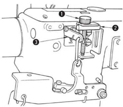
II. CONFIGURATION OF THE MACHINE COMPONENTS
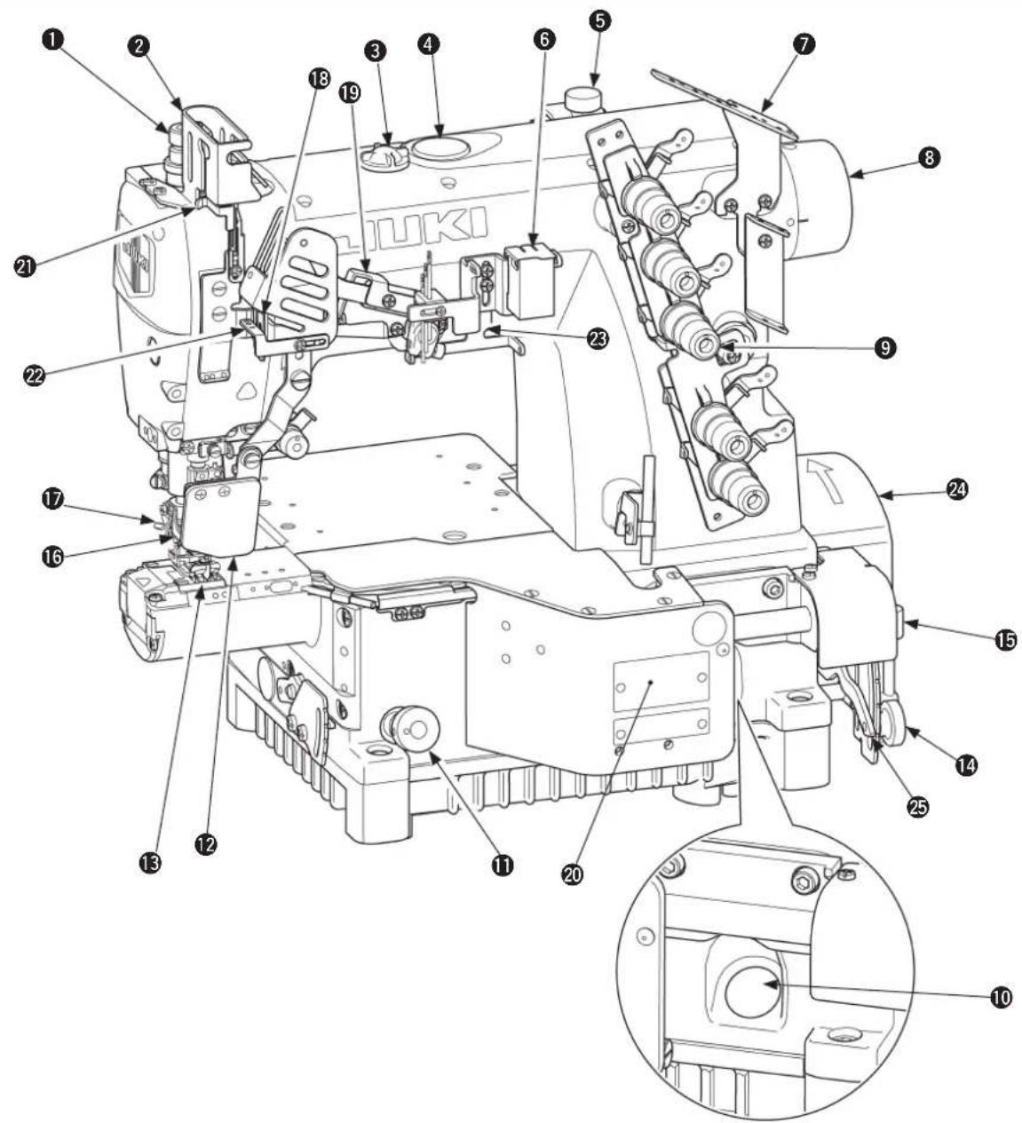
Presser spring regulator
2 Needle bar thread take-up cover
3 Oil circulation inspection windows
Oil hole cap
Micro-lifter
6 Needle thread silicon oil lubricating unit
7 Thread guide No. 1
Upper pulley
9 Thread tension nut
10 Oil gauge
1 Feed regulating knob
12 Eye guard cover
Throat plate
14 Differential lock nut
Micro-adjustment knob
16 Finger guard
17 Thread trimming knife
18 Rocking thread take-up receiver
19 Rocking thread take-up
20 Front cover
21 Needle bar thread take-up thread receiver
22 Rocking thread take-up thread guide
Silicon container thread guide
2 Belt cover
25 Differential feed regulating lever
Ⅲ. INSTALLATION

WARNING :
Do not insert the power plug of the motor into the receptacle until all works have been completed. There is a danger of injury by being caught in the machine.
1. Installing the machine head onto the table

WARNING :
The weight of the sewing machine is more than 42kg . Be sure to perform the work with two persons or more in case of unpacking, transportation or installation.
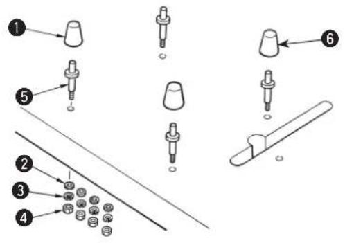
Top mount type
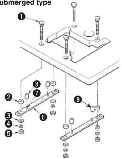
Semi-submerged type
Attach the pins and the rubber cushions as shown in the illustration and properly install the sewing machine.
Rubber cushion (Black) x 3
2 Washer
Spring washer
4 Nut
Pin
6 Rubber cushion (Gray) x 1
Attach the supporting board and the rubber seats as shown in the illustration and properly install the sewing machine.
Bolt
2 Spacer
Washer
Spring washer
5 Nut
Supporting board
7 Spring pin
Rubber cushion (Black) x 3
9 Rubber cushion (Gray) x 1
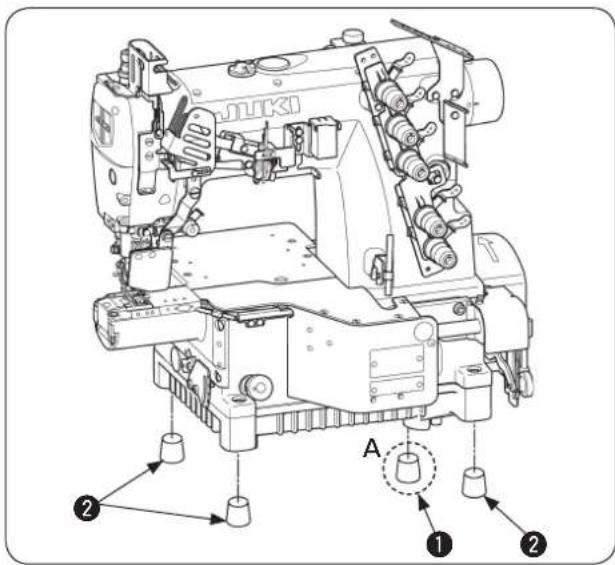
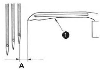
■ Installing the rubber cushion
Install the gray dust-proof rubber to section A only.
| Part No. Part name Q'ty | ||
| 1 | 40072505 Dust-proof rubber (Gray) 1 | |
| 2 | 13155403 Dust-proof rubber (Black) 3 |
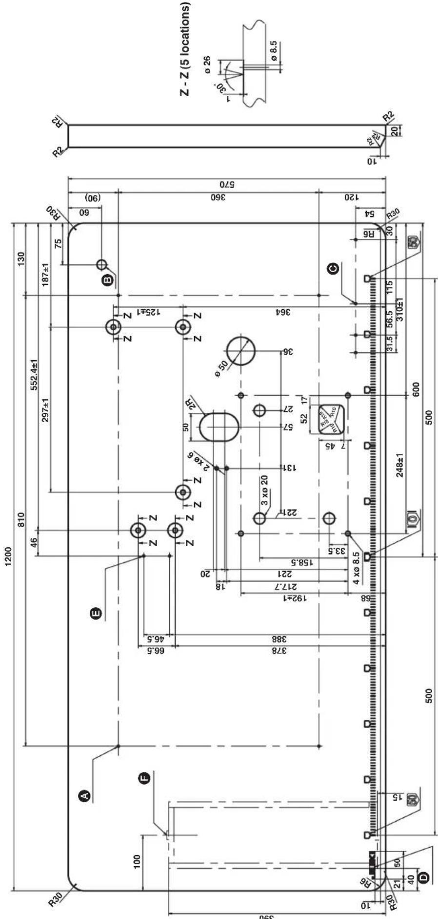
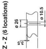
4- 0 3.4 on the bottom surface, depth 20 (Drill a hole at the time of set-up.)
③ Drilled hole 17
4-ø 3.4 on the bottom surface, depth 20 (Drill a hole at the time of set-up.)
JUKI logotype
2- 0 3.4 on the bottom surface, depth 20 (Drill a hole at the time of set-up.)
F Installing position of drawer stopper (on the reverse side)
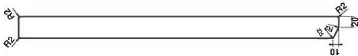
4- 0 3.4 on the bottom surface, depth 20 (Drill a hole at the time of set-up.)
B Drilled hole 17
4- 0 3.4 on the bottom surface, depth 20 (Drill a hole at the time of set-up.)
JUKI logotype
2- 3.4 on the bottom surface, depth 20 (Drill a hole at the time of set-up.)
F Installing position of drawer stopper (on the reverse side)
TABLE DRAWING (TOP MOUNT TYPE) FOR V-BELT SYSTEM
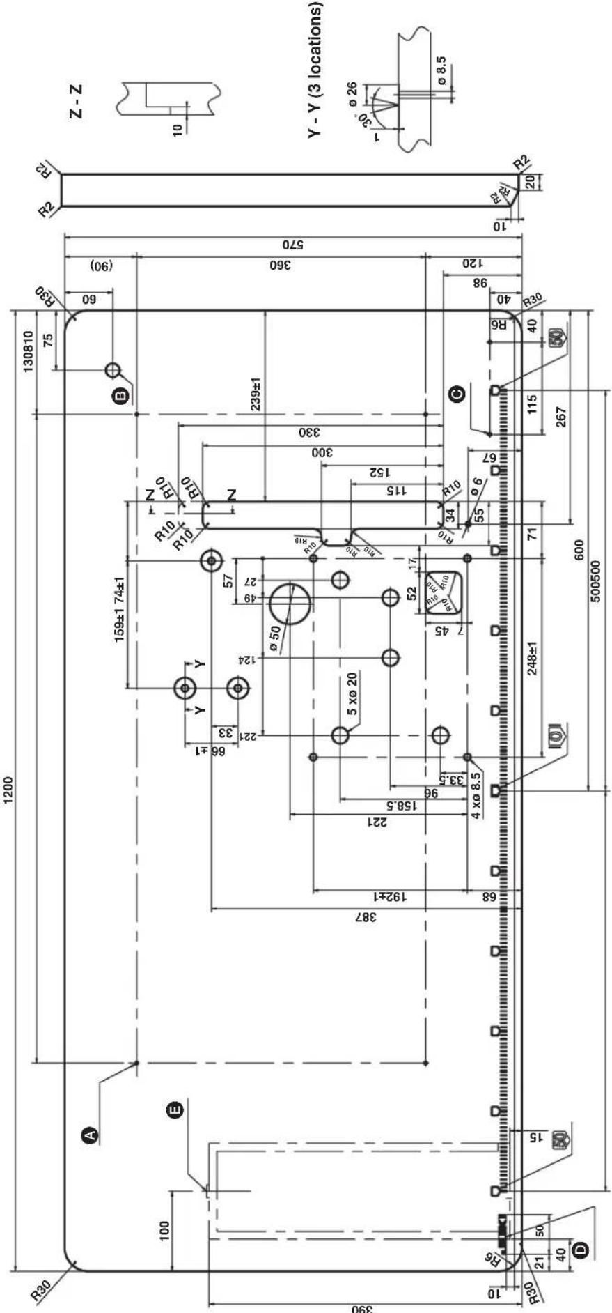
A 4-ø 3.4 on the bottom surface, depth 20 (Drill a hole at the time of set-up.)
B Drilled hole 17
4-ø 3.4 on the bottom surface, depth 20 (Drill a hole at the time of set-up.)
JUKI logotype
Installing position of drawer stopper (on the reverse side)
2. Selecting the motor pulley and the belt
Motor pulley and belt
| Speed of stitch (sti/min) | MF-7200D | |||
| 50Hz 60Hz | ||||
| Pulley size | Belt size | Pulley size | Belt size | |
| 3500 | ø80 | M-38 | ø65 | M-37 |
| 4000 | ø90 | M-38 | ø75 | M-37 |
- The table shows the numbers when a 3-phase 2-pole 400 W clutch motor (1 / 2 HP) is used.
- The commercially-available motor pulley near to the counted value is designated since the outside diameter of the commercially-available motor pulley counts by 5 mm.

Use a motor pulley which is adaptable to this sewing machine. The sewing speed exceeds the max. sewing speed of this sewing machine and machine trouble will be caused unless a motor pulley which is adaptable to this sewing machine is used.
3. Installing the motor
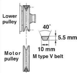
Use a clutch motor of 3-phase, 2-pole, 400 W (1/2HP). Use the M type V belt.
1) The motor pulley shifts to the left-hand side when depressing the pedal. At this time, install the motor so that the centers of motor pulley and lower pulley align with each other.
* For the installing procedure of the motor pulley, refer to the Instruction Manual for motor.
2) Install the motor so that the pulley rotates clockwise.

If the machine pulley rotates in the reverse direction, nomal lubrication cannot be performed. As a result, machine trouble will be caused.
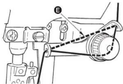
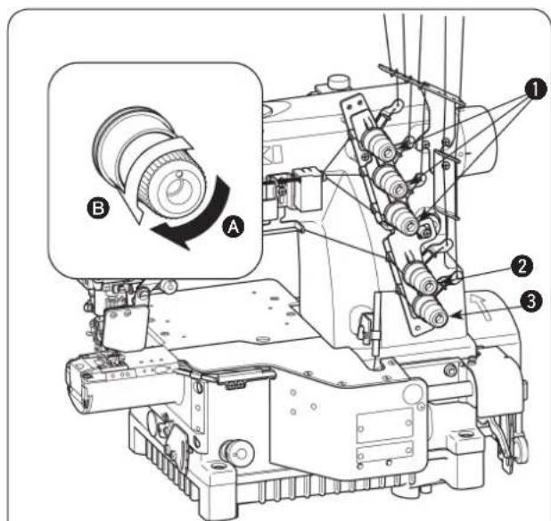
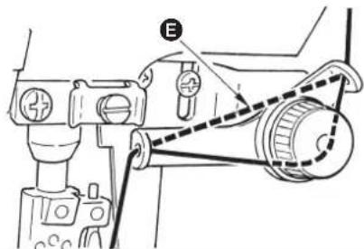
4. Setting the belt

WARNING :
When replacing the belt, be sure to turn OFF the power to the motor and ascertain that the motor has totally stopped rotating before starting the work. There is a danger of injury since hands or clothes may be caught in the belt.
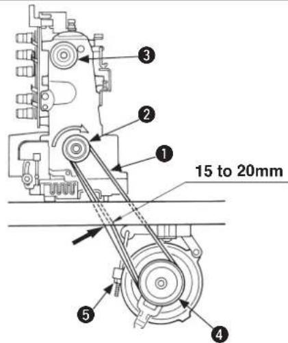
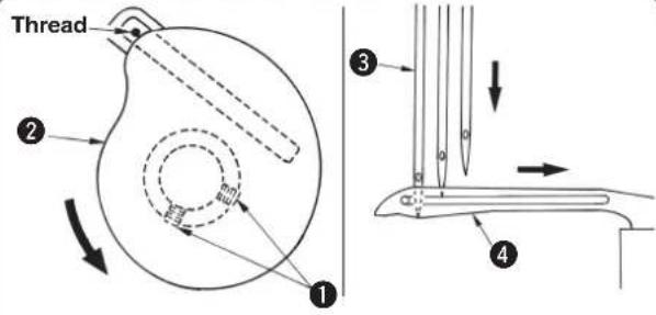
1) Fit belt ① to lower pulley ②.
2) Turning upper pulley 3, set the other side of the belt to motor pulley 4.
3) Adjust the belt tension so that the belt sags 15 to 20 mm when the center of the belt is pressed with an approximate 10N (1.02 kgf) load.
4) Securely fix the belt with lock nut when the belt has been set.

If the deflection of the belt is excessive when the sewing machine is operated, check again the belt tension.
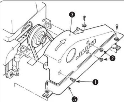
5. Installing the belt cover

WARNING:
Be sure to install the belt cover. If it is not installed, there is a danger of injury since hands or clothes may be caught in the machine or a danger of damage of the machine since sewing products may caught in the machine.
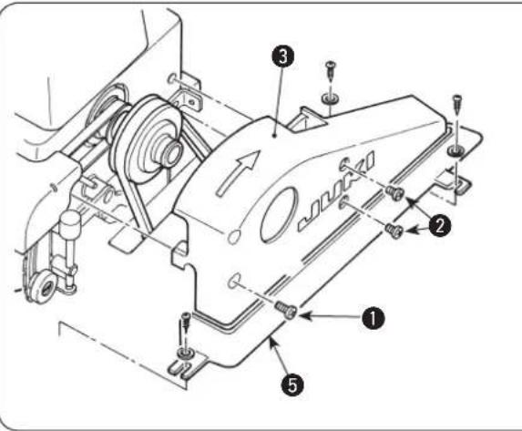
Install belt cover 3 as shown in the illustration.
1 and 2 are the fixing screws for belt cover 3.
* 2 has a shorter shank than 1 has.
- When the semi-submerged type table is used with the machine, cover ⑤ is not used.
- When the desktop type table is used, set up the machine head after having fixed cover ⑤.
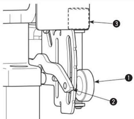
6. Installing the chain
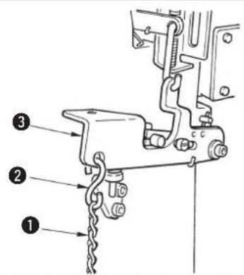
1) Hang hook ② of chain ① to press bar lifting lever ③.
2) Hook the other side of the chain to the pedal.
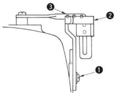
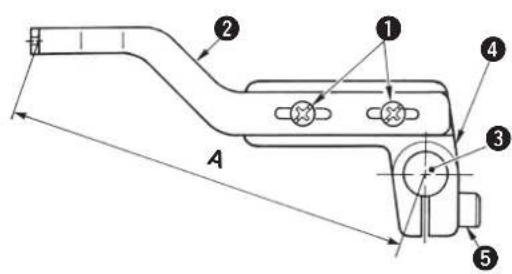
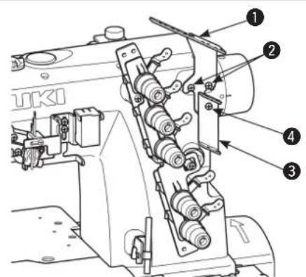
7. Installing the thread guide
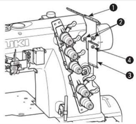
1) Install thread guide No. 1 supplied as accessories on the machine arm with screws
2) Install thread guide 3 on thread guide No. 1 1 with screw 4.
IV. LUBRICATION AND OILING
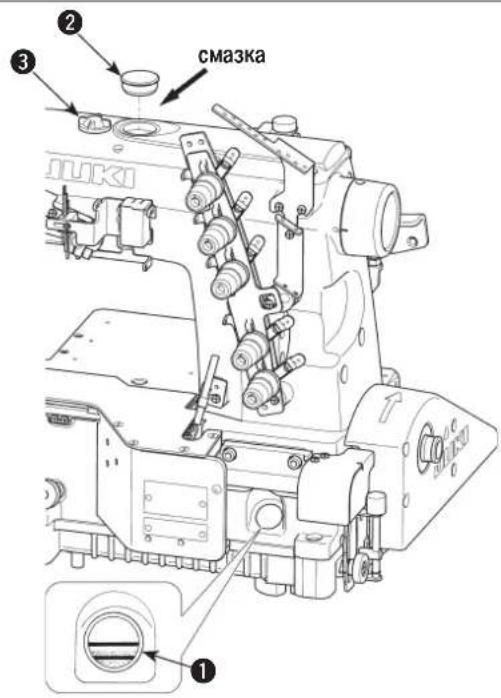
1. Lubricating oil
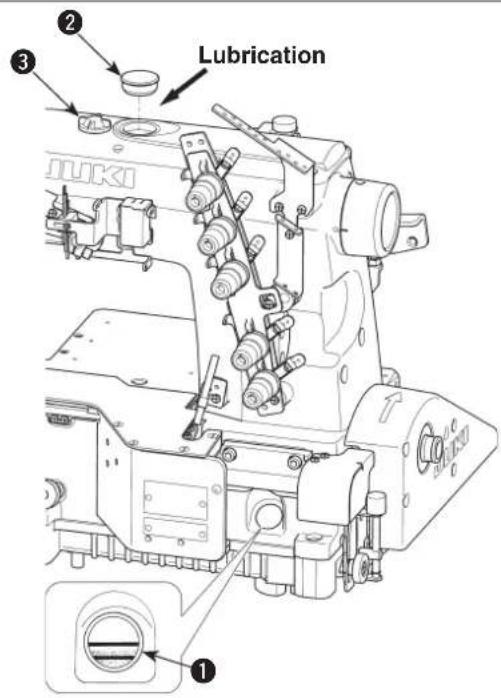
Lubricating oil has been taken out at the time of delivery. Be sure to supply lubricating oil before using the sewing machine for the first time.
Oil used: JUKI MACHINE OIL 18

Do not use oil addition agent since deterioration of lubricating oil or machine trouble will be caused.
Remove oil hole cap 2 on which "OIL" is indicated and fill the oil reservoir with lubricating oil up to the level between the upper and lower engraved marker lines.
1) Check oil gauge 1 and make sure that lubricating oil level is between the upper and lower two lines. When lubricating oil level lowers below the lower line, supply lubricating oil.
2) Make sure that lubricating oil comes out from the nozzle of oil circulation identification window when rotating the sewing machine. When lubricating oil does not come out, perform "Inspecting and replacing the oil filter". (See page 22.)
2. Oiling

The mechanisms inside the frame such as the needle bar, presser lift and spreader components are lubricated with grease. Never add oil inside the frame.

If inside of the frame is oiled, the grease will be expelled, resulting in mechanical failure.
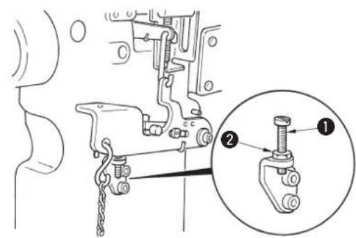
3. Replacing the lubricating oil

WARNING :
To protect against possible personal injury due to abrupt start of the machine, be sure to start the following work after turning the power off and ascertaining that the motor is at rest.
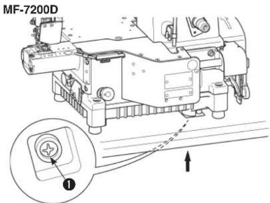
In case of the new sewing machine, replace the lubricating oil (JUKI MACHINE OIL 18) with new one after using it for approximately one month. Then replace the lubricating oil every six months.
1) Set a container to receive the lubricating oil under drain screw ①.
2) Remove drain screw 1. The lubrication oil is drained.
3) After the drain, wipe out the oil and attach the drain screw 1.
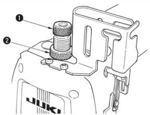
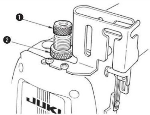
4. Silicon oil lubricating unit
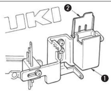
This sewing machine is provided with the silicon oil lubricating unit as standard. In case of sewing at a high speed, or using chemical thread or chemical fabric, use the silicon oil lubricating unit to prevent thread breakage or stitch skipping.
Oil used is silicon oil (dimethyl silicon).
Open cover 2 of silicon oil reservoir 1. Check to be sure that silicon oil reservoir for the needle thread is filled with silicon oil. If silicon oil is insufficient there, supply it (dimethyl silicon).

When silicon oil adhered to the components other than the silicon oil lubricating unit, be sure to wipe it out. If the components to which silicon oil adhered are kept without wiping out the oil, sewing machine trouble will be caused.
V. OPERATION
1. Needle
| Japan No. | 9 10 | 11 12 | 4 | ||
| German No. | 65 70 | 75 80 | 90 |
The needle used for this sewing machine is UY128GAS. For the needle No., select a proper needle in accordance with the sewing conditions.
2. Attaching the needle

WARNING:
To protect against possible personal injury due to abrupt start of the machine, be sure to start the following work after turning the power off and ascertaining that the motor is at rest.
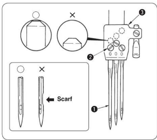
1) Loosen setscrew 2 of needle 1 with a screwdriver.
2) Hold the new needle with indented part facing to the rear and insert it into the hole in needle clamp 3 until the end of hole is reached.
3) Securely tighten setscrew 2 of the needle.
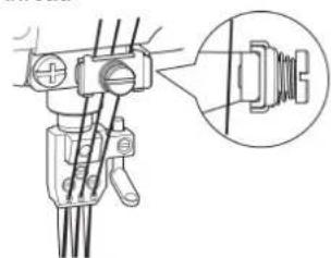
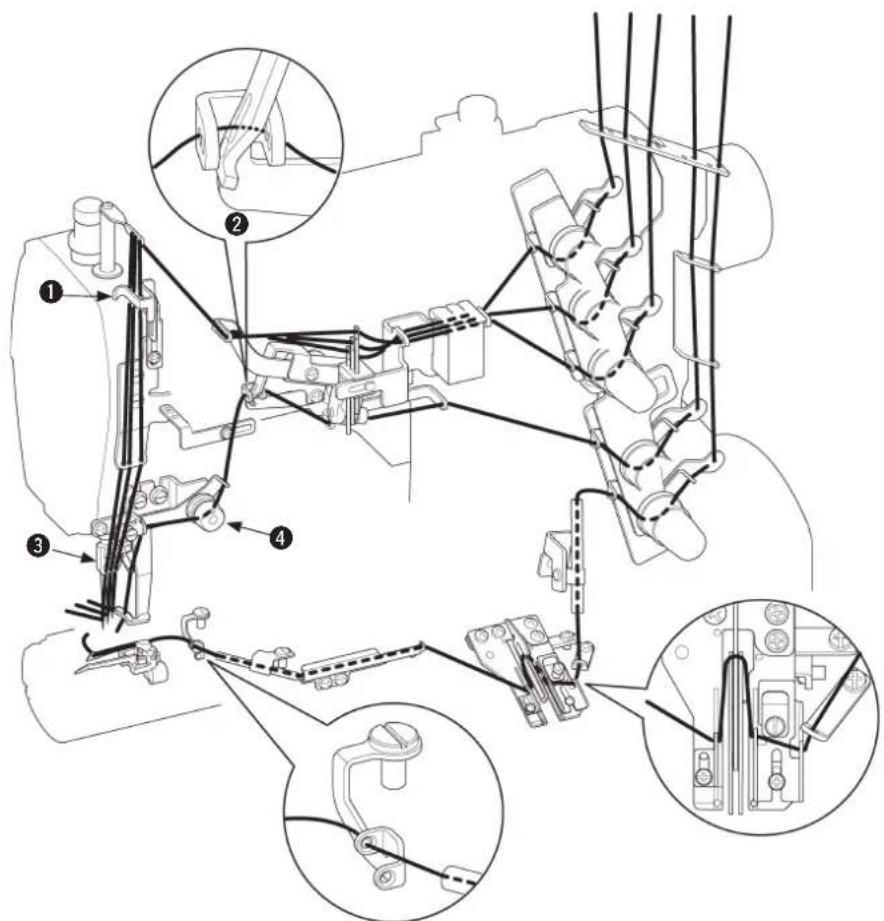
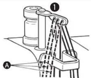
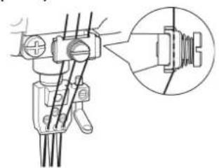
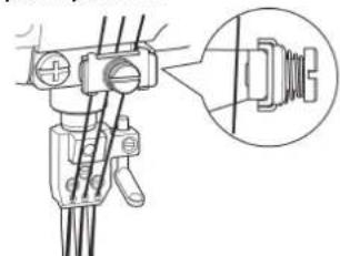
3. Threading the machine head

WARNING:
To protect against possible personal injury due to abrupt start of the machine, be sure to start the following work after turning the power off and ascertaining that the motor is at rest. If threading is wrong, stitch skipping, thread breakage, needle breakage or irregular stitches will be caused. So, be careful.
(1) Standard threading
Thread the machine head according to the following threading illustrations.
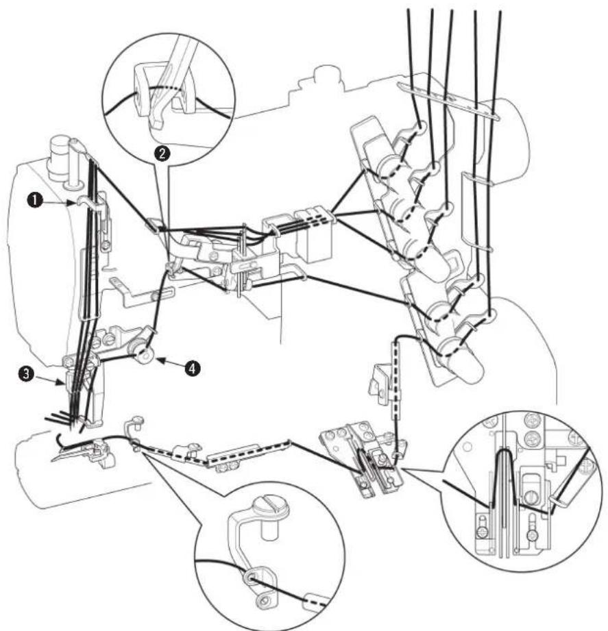
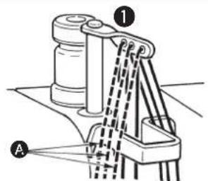
Broken lines A when stretcher thread is used
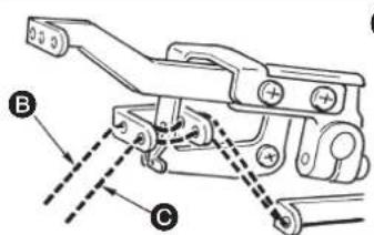
When covering thread is excessively loosened =
When covering thread is excessively loosened even after passing B = 0
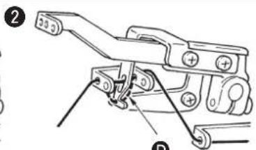
When covering thread is excessively tense = D
3
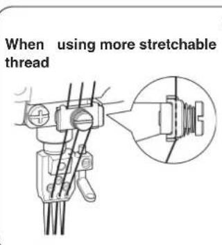
When using less stretchable thread
4
Broken line ③ when using more stretchable thread
4. Adjusting the stitch length

WARNING :
To protect against possible personal injury due to abrupt start of the machine, be sure to start the following work after turning the power off and ascertaining that the motor is at rest.
The stitch length can be infinitely adjusted from 0.8mm to 3.2mm .
- The actually sewn stitch length varies in accordance with kind and thickness of the materials.
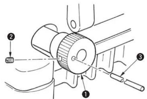
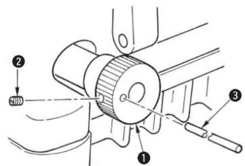
[How to change the stitch length]
Turn clockwise feed regulating knob 1 to increase the stitch length.
Turn it counterclockwise to decrease the stitch length.
- When making the stitch length 3.2mm or more Loosen screw 2 and turn clockwise feed regulating knob 1 to regulate the stitch length.
Push pin ③ until it goes to the end, and fix it with screw ②.
Use the machine within the range where feed dogs or feed dog and throat plate do not come in contact with each other.
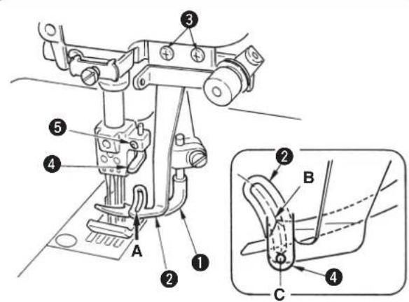
5. Adjusting the differential feed ratio
Loosen differential lock nut 1 and move lever 2 up to increase the differential feed ratio. Then the sewn material is gathered. Move lever 2 down to decrease the differential feed ratio. Then the sewn material is stretched.
Fine adjustment of the differential feed ratio can be performed with micro-adjustment knob 3.

There is a case where feed dogs or feed dog and throat plate come in contact with each other by the aforementioned adjustment according to the relation between the stitch length and the differential feed ratio. So, be very careful.
6. Adjusting the presser foot pressure
Decrease the presser foot pressure as low as possible to such an extent that stitches are stabilized.
To adjust the pressure, loosen lock nut 2 of presser spring regulator 1 and turn presser spring regulator 1.
After the adjustment, tighten lock nut 2.
Turning it clockwise to increase the pressure.
Turning it counterclockwise to decrease the pressure.
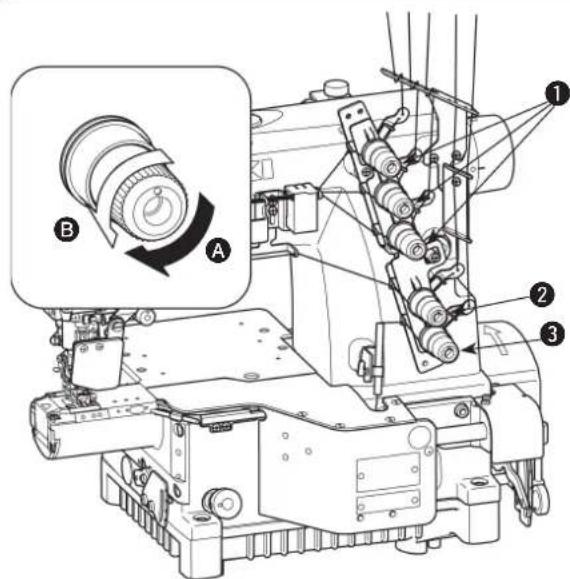
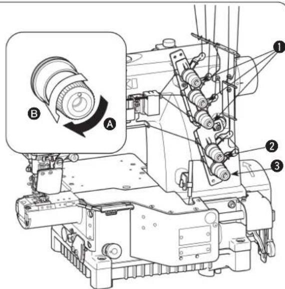
7. Adjusting the thread tension
A = Increase
B = Decrease
Adjust the thread tension with the following thread tension nuts.
1 Needle thread tension nut
Top covering thread tension nut
3 Looper thread tension nut
Turn clockwise to increase the thread tension.
Turn counterclockwise to decrease the thread tension.
VI. ADJUSTING THE SEWING MACHINE
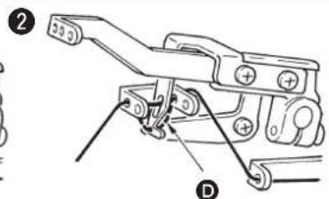
1. Adjusting the silicon container thread guide

WARNING:
To protect against possible personal injury due to abrupt start of the machine, be sure to start the following work after turning the power off and ascertaining that the motor is at rest.
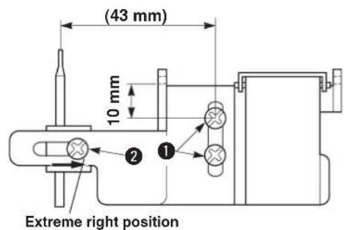
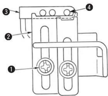
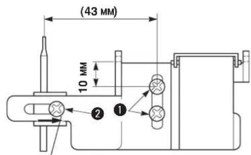
1) Loosen setscrews 1 and adjust so that the distance from the center of the setscrew on the upper side to the bottom end of the thread hole is 10mm . Then tighten setscrews 1 to fix the thread guide.
2) Loosen setscrew 2 and adjust the position from the center of screws 1 to the center of needle thread guide rod to the extreme right position (43 mm).
Then tighten screw 2 to fix the thread guide rod.
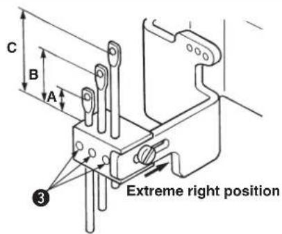
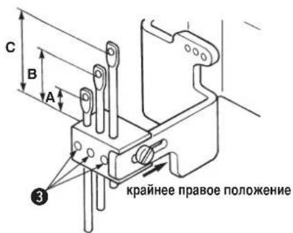
| A B C | |||
| Adjustment value | 13 mm 16 mm 19 mm | ||
3) Loosen setscrews ③ and adjust so that the heights of the respective needle thread guide rods are the dimensions as shown in the table. Then tighten screws ③ to fix the thread guide rods.
2. Adjusting the needle bar thread take-up thread receiver

WARNING:
To protect against possible personal injury due to abrupt start of the machine, be sure to start the following work after turning the power off and ascertaining that the motor is at rest.
Loosen setscrew 1 and adjust so that the bottom end to the center of the thread hole of needle bar thread take-up 3 aligns with the top end of needle bar thread take-up thread receiver 2 when the needle bar is in its lowest position. Then tighten screw 1 to fix the needle bar thread take-up thread receiver.
3. Adjusting the rocking thread take-up

WARNING :
To protect against possible personal injury due to abrupt start of the machine, be sure to start the following work after turning the power off and ascertaining that the motor is at rest.
1) Loosen setscrews 1, move rocking thread take-up to the right or left and adjust so that the distance from the thread hole to the center of rocking thread take-up shaft 3 is dimension A as shown in the il-lustration. Retighten screws 1 to fix the rocking thread take-up.
2) Adjust so that rocking thread take-up base4 is level when the rocking thread take-up is in its lowest position.
Retighten screw to fix the rocking thread take-up base.
| A | |
| Adjustment value | 90 mm |
4. Adjusting the rocking thread take-up thread receiver

WARNING :
To protect against possible personal injury due to abrupt start of the machine, be sure to start the following work after turning the power off and ascertaining that the motor is at rest.
Adjust so that the top end of rocking thread take-up thread receiver 2 aligns with the bottom end of thread hole 4 of rocking thread take-up 3 when rocking thread take-up 3 is in its lowest position, and fix it with screw 1.
5. Adjusting the spreader thread guide

WARNING :
To protect against possible personal injury due to abrupt start of the machine, be sure to start the following work after turning the power off and ascertaining that the motor is at rest.
Adjust so that the top end of thread guide thread path (rear) 3 of spreader thread guide 2 aligns with the lowest position of slot of spreader thread take-up 1 when spreader thread take-up 1 is in its highest position. Then tighten screw 4 to fix the spreader thread guide.
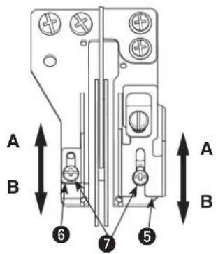
6. Adjusting the looper thread cam thread guide and the looper thread cam

WARNING :
To protect against possible personal injury due to abrupt start of the machine, be sure to start the following work after turning the power off and ascertaining that the motor is at rest.
[Adjusting the looper thread cam]
Adjust so that thread comes off from the highest place of looper thread cam 2 when needles come down and the top end of left needle 3 aligns with the bottom surface of looper 4. Then tighten screws 1 to fix the looper thread cam.
[Adjusting the looper thread cam thread guide]
When the thread drawing amount is desired to be decreased in case of 2-needle machine or the like, loosen screws 7 , move upward thread guides 5 and 6 and tighten screws 7 to fix them.
A = Decrease
B = Increase
7. Adjusting the looper thread winding prevention plate

WARNING :
To protect against possible personal injury due to abrupt start of the machine, be sure to start the following work after turning the power off and ascertaining that the motor is at rest.
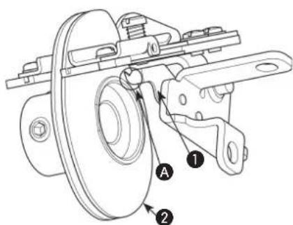
Adjust so that a clearance of approximately 0 to 0.3 mm is provided between the top end of section A of looper thread winding prevention plate 1 and the end face of looper thread cam 2.
8. Adjusting the looper

WARNING :
To protect against possible personal injury due to abrupt start of the machine, be sure to start the following work after turning the power off and ascertaining that the motor is at rest.
[Lateral position]
The relation between clearance A between looper 1 and the center of right-hand needle and the needle gauge is as shown in the table.
Unit : mm
| 2-needle 3-needle | |||
| Needle gauge | Return amount A | Needle gauge | Return amount A |
| 3.2 4.3 | |||
| 4.0 3.9 | |||
| 4.8 3.5 | |||
| 5.6 3.1 | 6 3.1 | ||
| 6.4 2.7 | 4 2.7 | ||
Loosen clamp screw 2 and laterally adjust looper holder 3 in accordance with the table.
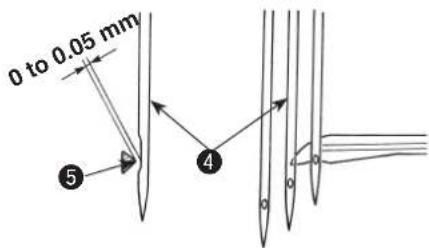
[Longitudinal position]
Adjust so that the clearance between blade point 5 of the looper and medium needle 4 is 0 to 0.05mm when the top end of the looper comes from the extreme right position to the center of the medium needle. After the adjustment, tighten clamp screw 2 to fix the looper.
- The blade point of the looper comes in contact with the right-hand needle when rear needle guard 6 does not work. So, be careful.
9. Adjusting the height of the needle

WARNING :
To protect against possible personal injury due to abrupt start of the machine, be sure to start the following work after turning the power off and ascertaining that the motor is at rest.
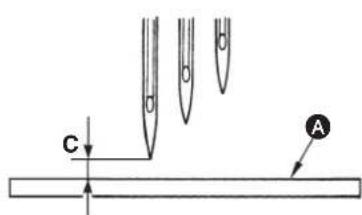
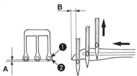
1) Equally adjust clearance A between needles 1 and needle holes 2 in the throat plate.
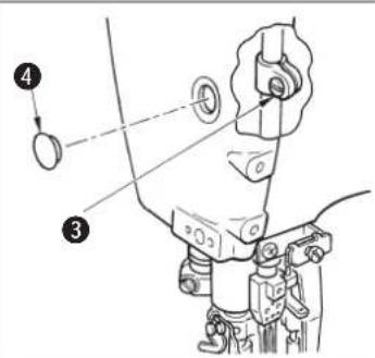
2) Adjust the height of the needle bar so that the top end of the needle hole of left-hand needle aligns with the bottom end section of the looper when the looper travels to the extreme right end and top end B of the looper protrudes by approximately 1.1mm from the left end of the left-hand needle, remove the rubber cap 4 in the face plate, and tighten needle bar bracket setscrew 3 to fix the needle bar.
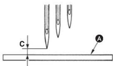
Reference: Height from the top surface of the throat plate A to the top end of left-hand needle, C when the needle is in the higher dead point is as shown in the table.
Unit : mm
| 2-needle 3-needle | |||
| Needle gauge | Height of left-hand needle, C | Needle gauge | Height of left-hand needle, C |
| 3.2 8.9 | |||
| 4.0 8.6 | |||
| 4.8 8.1 | |||
| 5.6 7.8 5 | 6 7.8 | ||
| 6.4 7.3 6 | 4 7.3 | ||
10. Adjusting the rear needle guard

WARNING :
To protect against possible personal injury due to abrupt start of the machine, be sure to start the following work after turning the power off and ascertaining that the motor is at rest.
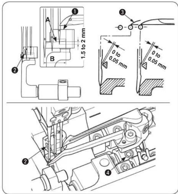
Adjust the lateral position of rear needle guard ① so that it receives the needle within the range of B when the needle is in its lowest position.
1) Adjust the height with setscrew 2 so that the distance from edge line A of rear needle guard 1 to the top end of right-hand needle is 1.5 to 2mm when the top end 3 of the looper comes from the extreme right end to the center of right-hand needle.
2) Make rear needle guard ① slightly come in contact with the right-hand needle so that the clearance between right-hand needle and top end ③ of the looper is 0 to 0.05mm when top end ③ of the looper comes from the extreme right end to the center of right-hand needle.
In addition, make rear needle guard 1 slightly come in contact with the medium needle so that the clear - ance between the medium needle and top end 3 of the looper keeps 0 to 0.05mm when top end 3 of the looper comes to the center of medium needle. Perform the adjustment with setscrews 2 and 4.
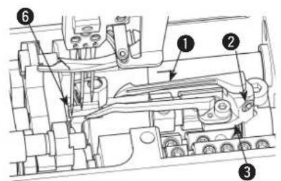
11. Relation between the rocking thread take-up timing and the needle thread loop

WARNING :
To protect against possible personal injury due to abrupt start of the machine, be sure to start the following work after turning the power off and ascertaining that the motor is at rest.
In case stitch skipping or thread breakage occurs due to excessive large or small needle thread loop even when performing threading in case of using stretchable threads or less stretchable threads described in "Standard threading", change the needle thread drawing timing of the rocking thread take-up and adjust the size of needle thread loop.
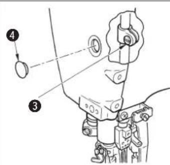
1) Loosen screw!
2) Move 2 forward or backward. The relation between the moving direction and the size of needle thread loop is as shown in the table below.
3) After the adjustment, securely tighten screw!
-
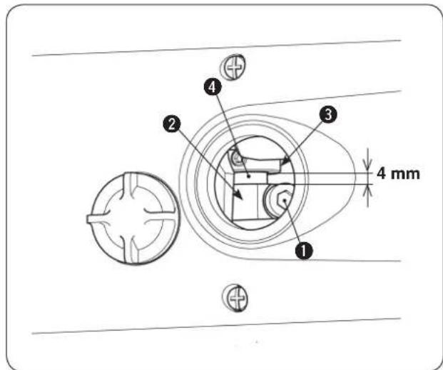
Clearance between crank ② and thrust collar ③ has been factory-adjusted to 4 mm at the time of delivery. (Engraved marker line on rocking thread take-up shaft ④ aligns with the edge of crank ②.
-
Size of needle thread loop
| Position of crank ➁ | Move forward | Move backward |
| In case of threading for standard seams | Loop becomes smaller. | Loop becomes larger. |
| In case of threading for soft seams | Loop becomes larger. | Loop becomes smaller. |
Note : The adjusting direction becomes reverse by way of threading. So, be careful.
- When screw
1 is loosened, the rocking thread take-up rotates due to the light weight. So, be careful. If

it rotates, refer to the item "Adjusting the rocking thread take-up".
- do not change the timing other than the aforementioned one since the sewing trouble will be caused.
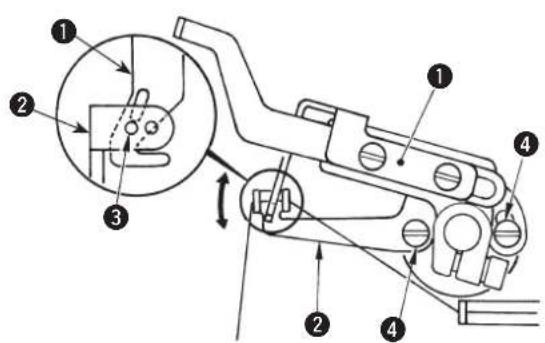
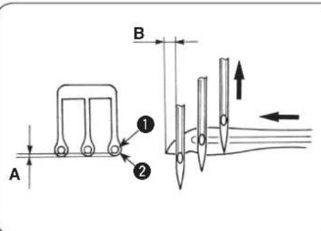
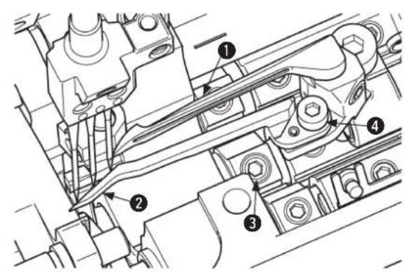
12. Adjusting the height of the feed dog

WARNING :
To protect against possible personal injury due to abrupt start of the machine, be sure to start the following work after turning the power off and ascertaining that the motor is at rest.
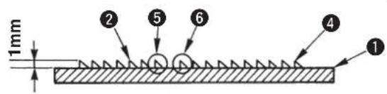
Adjust the height from the top surface of throat plate 1 to the rear end of main feed dog 2 to 1mm when the feed dog comes to its highest position and tighten setscrew 3 to fix the feed dog.
For the height of differential feed dog 4, adjust the height of front end 5 of main feed dog 2 to that of rear end 6 of differential feed dog 4, and tighten setscrew 7 to fix the differential feed dog.
It is the standard that throat plate 1 is flush with the feed dog when the feed dog is in its highest position.
13. Installing position of the spreader

WARNING :
To protect against possible personal injury due to abrupt start of the machine, be sure to start the following work after turning the power off and ascertaining that the motor is at rest.
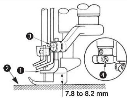
[Adjusting the height]
The height of spreader 1 is 7.8 to 8.2mm from the top surface of throat plate 2 to the bottom surface of the spreader.
Adjust the height with clamp screw 3 and fix the spreader.
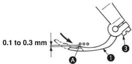
[Adjusting the longitudinal position]
Adjust so that the clearance between the spreader and left-hand needle is 0.1 to 0.3mm when spread - er 1 travels from the extreme left position to the right and section A comes to the front of left-hand needle. Then fix the spreader with clamp screw 3.
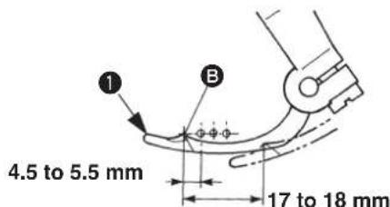
[Adjusting the lateral position]
Adjust so that the distance from the center of left-hand needle to section of the spreader 1 is 4.5 to 5.5mm when the spreader is in the extreme left position. Then fix the spreader with clamp screw 4.
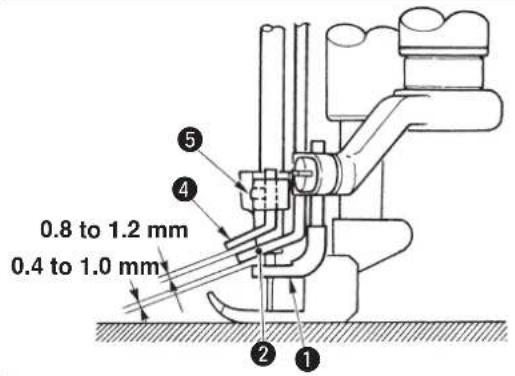
14. Adjusting the spreader thread guide and the needle clamp thread guide

WARNING :
To protect against possible personal injury due to abrupt start of the machine, be sure to start the following work after turning the power off and ascertaining that the motor is at rest.
[Spreader thread guide]
Adjust so that the clearance between spreader thread guide 2 and spreader 1 is 0.4 to 1.0mm . Then fix the spreader thread guide with setscrews 3.
- Adjust so that the center of slot A of spreader thread guide ② aligns with blade point B of spreader ① when spreader ① is in the extreme right position. In addition, allow the spreader thread guide ② to come near the needle clamp to such an extent that the spreader thread guide does not interfere with the needle clamp.
[Needle clamp thread guide]
Adjust so that the center of thread hole of needle clamp thread guide 4 aligns with center C of slot A when the needle is in the lowest position.
- At this time, adjust so that the clearance between needle clamp thread guide 4 and spreader thread guide 2 is 0.8 to 1.2 ~mm . Then fix the needle clamp thread guide with setscrew 5.
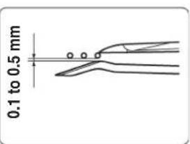
15. Adjusting the front needle guard

WARNING :
To protect against possible personal injury due to abrupt start of the machine, be sure to start the following work after turning the power off and ascertaining that the motor is at rest.
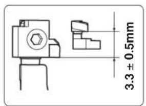
Adjust the height of front needle guard 2 with setscrew 4 so that it is higher by 3.3± 0.5 mm than the rear needle guard.
Adjust with setscrew 3 so that the clearance between the needle and front needle guard 2 is 0.1 to 0.5mm when looper 1 travels from the extreme right position to the left and passes the rear side of the respective needles.
- Allow front needle guard ② to come to the needle as near as possible within the range where needle thread smoothly passes in accordance with the kind or thickness of thread.
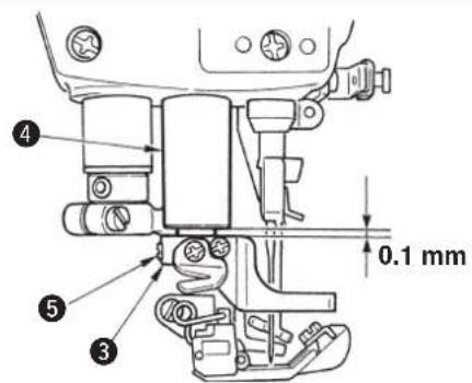
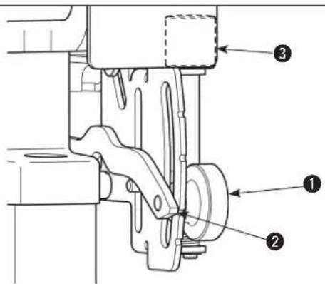
16. Adjusting the presser foot lift

WARNING:
To protect against possible personal injury due to abrupt start of the machine, be sure to start the following work after turning the power off and ascertaining that the motor is at rest.
1) To adjust the height of the presser foot, adjust the height of screw 1 so that the presser foot does not come in contact with other components and fix the presser foot with nut 2.
2) Adjust the position of the thrust collar so that the clearance between thrust collar 3 and presser bar bushing 4 is 0.1mm when the presser foot is lifted. Then fix the thrust collar with setscrew 5.
17. Adjusting the micro-lifter

WARNING:
To protect against possible personal injury due to abrupt start of the machine, be sure to start the following work after turning the power off and ascertaining that the motor is at rest.
When micro-lifter knob 1 is turned counterclockwise, micro-lifter stopper 2 lowers and comes in contact with presser lifting lever 3. Then the presser foot goes up. Adjust the height in accordance with the sewing conditions.

When the micro-lifter is not used, turn clockwise micro-lifter knob 1 and fix microlifter stopper 2 at the highest position.
VII. MAINTENANCE
1. Cleaning the sewing machine

WARNING:
To protect against possible personal injury due to abrupt start of the machine, be sure to start the following work after turning the power off and ascertaining that the motor is at rest.
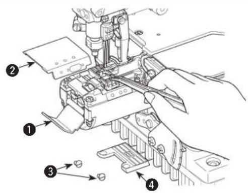
Open side cover 1 and cylinder cover, right 2. Remove screws 3 and then throat plate 4. Then, clean up the throat plate slits, feed dog teeth and the area surrounding them.
After cleaning, fix throat plate 4 with setscrews 3.
2. Replacing the lubricating oil

WARNING :
To protect against possible personal injury due to abrupt start of the machine, be sure to start the following work after turning the power off and ascertaining that the motor is at rest.
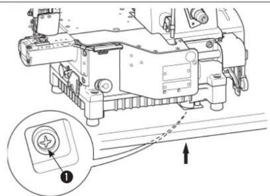
In case of the new sewing machine, replace the lubricating oil (JUKI MACHINE OIL 18) with new one after using it for approximately one month. Then replace the lubricating oil every six months.
1) Set a container to receive the lubricating oil under drain screw ①.
2) Remove drain screw. The lubrication oil is drained.
3) After the drain, wipe out the oil and attach the drain screw 1.
3. Inspecting and replacing the oil filter

WARNING :
To protect against possible personal injury due to abrupt start of the machine, be sure to start the following work after turning the power off and ascertaining that the motor is at rest.
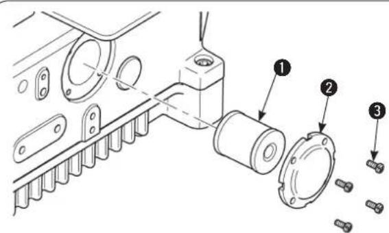
Normal lubrication cannot be performed if dust collects in oil filter 1. Inspect it every 6 months.
1) Remove oil filter cap 2, and draw out oil filter 1 to inspect it.
2) When oil filter 1 is clogged with dust, replace it with a new one.
3) After the replacement, fix the filter cap 2 with screws 3.

When removing the oil filter cap, lubricating oil collected in the filter will leak out. So, be careful.
DEUTSCH
A = Augmentation
= Diminution
A = Diminution B = Augmentation
[Position transversale]
OchOBhIe npedoctoPOXHOCTH
- Y6eHNTecb B TOM, YTO npOHTaNN HnCTpyKuHIO NO 3KcNpyataun I dpyrne NORCHIOUHe DOKyMeHTbI, NOCTABNEmBle C npHnAaNEXKHOCTMMAHNbI npExKe, YEM NaHETe NCNoB3OBaTb MaunHy. BepexHo xpaHIne HnCTpyKuHIO NO 3KcNpyataun I nOraChHOUIue DOkymeHTbI No6n3oCTOn OpaOchero Mecta Tnoro, YTO6bl MoXHO 6blIO 6blCTpo IN npOHTaB.
- Copepkahme 30t qachn Bknoaet nyhkb, KOTOpbHe He copepkatcB cneuufkaunx Baewero n3dennia.
- y6eintecb TOM, yTO HAdEN 3aunTHbIe OcKN, yTO6bI 3aunHTbcr OT HeCuaCTHO rO Cnyar, BblBaHHORo NONOMKOrnrrbl.
- Te, KTO HcnoIb3yET KapnIOCTMMyJrTOp, DoJIKhbI npHcTynaTb K pa6Ote Ha MaunHe nocTe KOHCytbTaun C BpaOH.
YcTpoIcTb6e3oNaChocTn npdynpeXdaOuune HakJeKn
- 6eHNTecb B TOM, YTO pncTynaete K pa6ote Ha MaunHe, H KOtopo OOno HIN HeckOJko yCTpoHCTB 6eONaCHOCTn PpABNJIbHO yCTAHOBNEHO HOPMaJIbHO pa6otaet, YTO6bl NpeD0TBpaTNb HeCAcTHbI CNYaH N3-3a OTCyTCTBnYCTPOHCTBa 6eONaCHOCTn.
- Ecnn KAKoe-To n3 yctpoiCTB 6eONACHOyDAnEHO, Y6eHNTcB TOM, YTO 3aMeHNn ERO N npOBepnN, YTO OHO HOpMaNBpa60TaET, YTO6bI PpeoTBPaHTb HecuacthBn Cnyuay, KOTOpB MoKET npBecTN K TpaBME Nm CmeTN.
- Y6eNTecb B TOM, YTO npdynpexkaIOUne HAKNeKN HADEXHO 3aKpeNNEbHa MaUNHe, INX XopoOo BVnHO, YTO6bI npedOTBpaTb HeCvAcTHbI CNyAan, KOTOpB MoKET pINBeCTN K TpaBMe Nn CmepTN. Ecn KaKa-TO n3 HAKneeK 3anaKaHa Nn OTKnEHNACb, Y6eNTecb B TOM, YTO 3aMeHnn ee HOBO.
PpimmeHHeHmOndnKaua
- HnKorda He nCnOJb3yIte MaunHy dny KaKHX-NHbIX cIeNe I CnOcOB MCNOJb3OBAHN KpOME Tx, YTO ONCAHB DaHHo IHCTpykUIN NO 3KcNlPyatauIN, YTO6bI ppeOTBpaNTb HecuaTHb CNyua, KOtOpbIM MOXET PnPBECTN K TpaBM He mCmeTn. JUKI He hecet OTBcTBeHHocTN 3a y6bITKn, TpaBM b INN CMeptb, ppon3oWeJHne H3-3a NcNoJIb3OBAHN MaunHbI He no Ha3NaueHIO.
- HnKOrHa He nepeDeIbIaIte H He MoDnHnIuPyIte MaunHy, YTO6bI npeOIBpaITb HeCuaTbH Cnya, KOTOpBIMoKeT npNBecTN K TpaBMe IIN CmeptN. JUKI He Hecet OTBcTBeHHocCTNa y6bIK, TpaBmI IN Cmeptb, pOn30weJwne N3-3a TORO, 7TO MaunHbI b6bIa NepeDenaHa II MOnDnHnIpObaHa.
ObueHne HtpenpoBkn
- T06bI npedotBpataHb HecacThbI cnyaH 3-3a IIOXoro 3HaHHMaHbI, Ha He dOnJxep HpaOtaTb TohkoTOT onepatopom, KOTOpbI 6bI OByeH N HATpeHnPOBaH paOToaTelem, KaK Be3oNacHO paOToaTb Ha MaunHe, pno6peN COOTBeTCTByIOme 3HaHH N HABIK paOToI. T0, paOToaTeJI DoJxKe YcTaHOBtB PAn H oByeHH N TpeHPOBOKdne onepaTOPOB IN obyaTH x3apaHe.
Cnyan, B KOTopbIX DOJNXHO 6bITb BByIKIOHcHc3NeKtpONHTaHHe MaINHBI
BbIKIOHHe He 3IeKTPoNTAHN: BbIKHOHTe BbIKIOUaTeJIb 3JIeKTPoNTAHN, a 3aTeM BbITaUNTE WtENCeJIb n3 PO3ETKn. 3To OTHOCITc K CNeDyUOUM CnyuAM.
- Y6eIITcB TOM, yTO BbIKIOUHIN 3JekTPoNTaHHe, ecN O6hApyKIne KaKoe-H6yDb OTKnOHeHne B pa6ote nn OTKa3 06OpYdoBaHn, INN B cnyae OTKIOUeHnE 3JekTPoNTaHnR, yTO6bI ppeDOrbpaTb HecuactHbI CnyaI, KOtOpBI MoKET npNBecTN K TpaBME INN CMEPTN.
- 206bl npedotbpaatnb hecacthb cnyauh n3-3a pe3koro 3anycka Maunnbl, y6eintecb B TOM, TTO BInonHnn Cneyooune onepaunnoocne BIKIOHcHn 3NEKTPoNTAHn. Jnmaunn, HmEOUnx MOTOP cuenneHn, B qACTHOCTN, y6eINTECB, TTO BInonHnn Cneyooune Oepaunn noCne BIKIOHcHn 3NEKTPoNTAHn N TO Maunna NONHOCTbO OCTAHOBINACb.
2-1. Hanpimep, npodebaHne HHTn Yepe3 TaKHe Yactn, KaK Nrrna, nTInTeNb, pa3dEnIeNb N T.D., Yepe3 KOtOpBle OHa DoJXKa 6bItb npoTeA, mnn 3aMeHa KAtyUKN.
2-2. HanpMep, 3aMeHa nn peryNipOBKa Bcex qacteMaunHbI.
2-3. Hanpimep, ocmatpmba, pemOHnpy, nCTMaunHy nIOCTabJMy MaunHy nocpe pa60tbl.
-
6eHTEcB TOM, 7TO H3BNeKaete WTeNceNB 3NEKTPoNTaHn H3 po3eTK, DEPKAcb 3a Hero, a He 3a Whyp, 7To6bl npedotBpaTHTb NOPaXeHHe 3NEKTPuYeCKM TOKOM, yTeKY TOKA NIN BO3rOpaHne.
-
6eIMTeCB B TOM,TOBbIKIOUHINN 3NEKTPoNTaHHe BCaKN pa3, KOrda octaBnreMaunHy B nepepbIbx Mekdy pa6oToi.
- 6eintecb TOM, yTO BbIKIOHIN 3NEKPTponHTAHne B cnyae npekpaueHn 3NEKTPoCH6KeHH, 706bl npedotBpATNB Hechacthbn cnuya, H3-3a noIOMKn 3NEKTPoo6OpyOBaHH.
Ipeodoctopoxhoctn, kotopbie cJeayet npedpinnHMaTb Ha pa3JNUHbIX cTaNx pa60tbi
TpaHcnpTnpOBka
- Y6eHNTecb B TOM, yTO NOHMAeTe n nepemaeTe MaunHy 63onacbIM cnocobom C yyeTOM BEa MaunHbI. O6paHTecb K HCTpyKnnn IO 3KcNpyatau nn IOnpeJeHnMaCCbl MaunHbI.
- Y6eHNTecb B TOM, yTO npEINPNHnIOOCTaTOUHbIe MEpbI NO oBcneHHeIO 63OnaCHOCTN, TTO6bI ppeoTbpATnTb naeHMeMaHNbI,do ee noDbema HnNE PepemeueHn, TTO6bI npEOTbpATnTb HeCuaCThBn CnyaA, KOTOpBm MoKET npNBecTN K TpaBMn cmeptn.
- Nocne toro, kac pacnakyete MaunHy, HNKOrda NoBToPHO He ynakobbIaIe ee dIra TpaHcnpTnpOBKn, YTO6bl 3auHTb MaunHy OT noNOMKn n3-3a HeoxkndHNO abapnn nn naDeHH.
Pacnakobka
- 6eIntecb B TOM, yTO pacnakobann MaunHy B npeHncanHom nopAke, T06bl npeoTbpaHTb HecacthBm cnyauK, KOTOpbIM MOKET npNBecTN K TpaMe Hn CmeptN. B clyae ecn MaunHa ynakOBaHa B RnK, Oco6eHNO y6eNTecb B TOM, 4TO TuaTeNb-HO npOBepnn HnHnue rBO3dei. IBO3n DoJXhb 6bIty daneHbl.
- Y6eNTecb B TOM, yTO npOBepnIpaCNoIOXeHHe zHTpa TjXeCTMaunHbI n AKKypaTHo 3BJeKnte ee n3 yNAKOBN, yTo6bl npedOTbpaTntb HechacthblcnyaH, KOtOpbl MoKET pNBECTN K TpabMe HJN CMEPTN.
YctaHObKa
(1) CToI n OCHOBaHnE CToIa
- Y6eIntecb B TOM, QTO hCnONb3yeTe opRnHaNbHbI CTJOL JUKI n OCHOBAHne CToJa, qTO6bl npEOTBpATNTb HecacThbI cnUyai, KOTOpBI MOXET npNBECTN K TpaBME NIN CMEPTN. EcII NCnONb30BaTb HeOpRnHaNbHbI CTJOL n OCHOBAHne CToJa, TO Bbl6epHTe CTJl N OCHOBAHne CToJa, KOTOpBIE B COCTOARNN BbldePkAaTb Bec MaunHbI CNUY IpOTNBodeiCTBn BO BpeMa pa6oTbI.
- Ecnn cTOnI opopydoan Koneckamn Ha HOKKax, y6eTeCb B Tom, yTO nCNOJIb3yeTe KonecKn C 6NOKnpOBOHyIM MEXAHINOM N 3a6NoKpyte INx, YTObl Oe3OanCTb MaunHy BO Bpem pa60tbl, oCnykBaHn, oCMOTpa n peMOHTa, YTObl npDoBbPAHTb Hecyacthbl cnuya, KOtOpbl MOKeT pInBeCTN K TpaBME nIN CmePTn.
(II) Ka6eJIb n 3JIeKTPoPnPoBOKa
- 86eintecb b TOM, yTO Ka6eIb He NOBepraetc qye3MepHOMy CINOBOMy BO3deNCTBNIO BO BpeMnCNOlb3OBAHn, YTO6bI npedotBpaNTb nopaxHe nEeKtpueckm Tokom, yTeky ToKa IINBOCNlAmeHeHne. Kpome TOrO, ecn Heo6xOIMo IpnoJXITb Ka6eJIb PdOM c pa6oTaIOUmm uactTm, TAKIMn kak KInHOBoi peMeHb, y6eINTecb B TOM, yTO oBeCneuINI pOmeKyToK He MeHee Yem B 30 MM Mekdy pa6oTaIOUmm uactTm n Ka6eIeM.
- 86eintecb TOM, yTO HET NCKPRAUx COEHNHEHNI, YTO6bl npeDoTbPAHTb NOPaXHeHne 3NEKTPuYeCKM TOKOM, yTeKY TOKa INN BOCIIAMEnHeHne.
- 6eHNTecb B TOM, 70 HADEXHO COEHNNN pa3bEmbl, 706bl npeoTbpATNTb npaXHe NJIeKTPuecknM TOKOM, yTeKY TOKa HIN BOcNlameHHeN. Kpome TOrO, 6eHNTecb B TOM, 70 ydAnreTe pa3bEm, depka erO 3a Kopnyc.
(III) 3a3eMJIeHne
- 86eHNTecb B TOM, YTO 3NEKTPNK yCTAHOBIN COOTBETCTBYUO uTENCENBHy BO NIKy, YTO6bI npeoTBPaTnTB HeceactHBn CnyaB, BB3BaHHb IYTEKOH TOKA HIN 3NEKTPNueCKN npo603NEKTPNueCKO npoHocTN dN3NEKTPKa. Kpome TOrO, y6eHN- TECb B TOM, YTO NOCDoeHNHNI WTeCNCEhByu BO NIKy C 3a3EmEHHbIM BixODOM K PO3ETKE C COOTBETCTBYUOM BBIXODOM 6e3 NCKIOUeHNI.
- 6eNTcB TOM, yTO pON3BEN 3a3emnHHe n C NMOUbO 3a3mNHOero Ka6en, YTO6bl PpeD0TbPAHTb HecuactHbI cny-ay, KOtOpBI MOKET 6bITb Bb13BAH yTeKoI TOka.
(IV) Motop
- 6eNTecb TOM, yTO nCnOJIb3ye Yeka3aHHbI MToP (opRnHaJIbHOe I3dEne JUKI), YTO6bl npedotBpATNB HechactHbI cnuyai, Bbl3BaHHbI neperopAHem MOTopa.
- Ecnn wipokoocTynhmOTOp cuenneHnncnoh, y6eHTbcB TOM, TTO BbIpaHmOTop, 06pyoBaHnKpbikkoiknKINBA dnppeDtbpaeHHa3nytbAHn, YTo6bl3aunTbero OT HamaTbIBAHNKNINHOBOPEMH
Ipeepnauonpa6bI
- 6eNTecb TOM, yTo pa3bEmbl KabeHn He noBpeKdEhbl, a KOHTaKbI He ocnaBn Npep BKnHouEHem 3JekTPoNTaHn, YTObI npedTbPaTb HecuaTbHcnyaH, npnbOdaun K TpaBMe nn Cmeptn.
- HnKorda He cyte pykB B DmXyuececAactMaunHbI, YTO6bl PpeoTbpaNTb Hecuacthbi Cnyaai, KOTOpbi MOKeT npBeCTN K TpaMe nIN Cmeptn.
Kpome toro, y6eHTecb, YTO HanpaBHeHne BpaueHna SKNBa COOTBeCTByet HAnpaBHeHIO, NOKa3bIBaEMOMy CTpeNKoHa
sKNBE. - Ecnn cTOnI 6OpyDobAH KONEcKAMn Ha HOxKax, y6eInTeCb B ToM, YTO HcNtB3yTe KONEcKN C 6NOKpOBoOHbIM MExaHIN-MOM INI peryJrTopAmn n 3abNOkpyIte Ix, YTO6bl IpeDoTbpaNTb HeCactHbI CnyaH N3-3a CnyaHORO DBNXEHN MaHIN-HbI BO BPEMa pa60tbl.
BoBpempa6oTbI
- CnEeHTe 3a Tem, YTO6bI BaaH naJIbCuI, BOJocB, OJekDa HIN YTO-To eHepacnoNaraoCbCNKOM 6n3Ko C DnKxuMnCRACTAMN, TAKIMN KAK MAXOBNK, pyHoi WKNB I MOTOP, KOrDa MaunHa pa6Otaet, YTO6bI PpeDtBpaTb HeCuaCTHBmCnyaH N3-3a 3aTARHBAHNA, YTO MOKeT pInBeCTN K TpaBMe HIN CMEPTN.
- He pacnojarate naIbci pIaOM c IRIOn IIN B KpbIekepeIyara HHTeHATKHO npCnOc6NeHn npB KJIIOueHn 3NEKTPonNTA HN KORda MaHHa pa6oTaET, YTO6bI npedOTbpaTb HeCuaCTb CnyaH, KOtOpBm MoXET npNBecTN K TpaBMe HIN CMEPTN.
-
Maunha pa6oatac C blicokon ckopocbH. HkOrda He BODntpe pykamn Okono DnBkyuXcxraacte, taNX kak netntntb, pacnpedentnb, nrobnua, kpoohn HOK dnoobpe3kn TKAHN BO BPempa6tbl, 106bl 3aunntb Baun pykn OTpabM. Kpome toro, y6dntecb B TOM, 10 To BBkIOUHIN 3NEKTponTahne, m Maunha NOnHOCTbO OCTaHOBNAcNbpexde, Ym MeHrtb HNTb.
4.CneiTe 3a Tem, TTo6bI nalbci Hnn dpynr Heacn BaWero TeHa He 6bln 3axaTb MeKdy MaunHOn n CTonom, npn nepemeue Hnn MaunHy nn npn 3ameHe ee Ha cTone, TTo6bI npedotBpaTb HecYactHbIn CnyaH, KOtOpBm MoXeT npnbecTN K TpaBMe Hnn Cmeptn. -
Y6eIntecb B TOM, yTO BBIKIOUHUN 3NEKTPoNHTaHne HTO MaUNHa MOTOP NOINOCbIO OCTAHOBUNcB npexde, Yem CHrTb KOxuyx peMHn KINHOBOI peMeHb, yTO6bI ppeD0TBpaNTb HeCuaCTbI CnyaI, Bbl3BaHHbI pe3KNM 3aNyCKOM MaUNHbI NIM MOTopa.
- Ecn Ha MaunHe Ncnonb3yETc CepBOMOTop, MOTOp He npOn3BOuNT Wm, KOrda MaunHa B NOKoe. Y6eDntecb TOM, YTO He 3a6bln BbIKIOUATb 3JeKTPoNHTAHne, YTO6bl IpeOToBpaTb HecVAcTHbI CNyAaH, Bb13BaHHbI pe3KNM 3AnycOM MOTopa.
- HnKOrda He nCnOJIb3yIte MaunHy C 3aKpbITbIM OxnaXdAIOUm OTBepCTHm E6JOKa NHTAHN MToPAp, YTO6bl IpeDoTbPaTb BocnnAmeneHHe n3-3a neperpeBa.
Cma3bBaHHe
- Y6eHNTecb B TOM, qTO nCnOJIb3yTe opRnHaIbHoe MacNo JUKI n opRnHaIbHyU Cma3Ky JUKI nraJyactei, KOTOpBie HxKHO CMA3aTb.
- EcIIMacno nonaTeB rna3a HnHa TeNo, HeMeJeHNO CMOte erO IToToro, YTO6bl IppeoTbpaTb BocJIaMeHeHne nn pa3dpaxKeHne.
- EcIn CnyaHb BInbete MacNo, HemeDHeHo 6paTncB K bpaY, YTO6bl IpEoTbPaTntb InapeO INP pBOy.
06cnykubahne
1.ПпгпрдьрашенинесчадыслуаeB,ИЗ-3a ПLOXORO 3HAHNA MaUNHbI,peMOHTOM pERYNIPOBKOДОЛKHbI 3AHIMatbCnEuaHNTbCEPNCHOHcnyK6bI,KOTOpBIE NOHOCTHBO3AOKOMBIcMaUNHOB PpeJenaxOblaCTN,ONpeJenEHNOB HnHCTpykunnoNo3KcNpyatau.Ny6eHntecbBTOM,YTO NcNoB3yeTe opRnHaJIbHbIe YactN JUKI,3aMeHryIIO6yUH3aCTeMaINHBJ.JUKI He Hecet OTBetCTBeHHocTN 3a IIO6oHecuACTHbI clyaH IN-3a HENpaBInhoro peMOHTa INn peryNipOBKn, INn INcNoJIb3OBAHNmII6bIX qacteKpOMEopRnHaJIbHbIX qacteJUKI.
2.Дпгпрдьрашенинесчадыхслуаь,И3-3aПNOXOrOЗHAHЯMaSHHbIИПОРALEHЯЗЕТРЧUECKMTOKOM,OBpaTNTecbК3NEKTPNkyCBOEKOMPahHHJUKIИПДСТРБЛOTOPBaBAWeMaHOHeДЯPEMOHTaNObcLNYKBAHY(BKNIOUAY3NEKTPponpoBDky)3NEKTPPueCEKHXKOMNOHETOB.
3. BbINOHRA peMOHT HNIO BCJyKINBaHNE MaunHbI, B KOTOPo NcNOB3yOITc NHEBMATNueCKne Yactn, TaKHe KAK NHEBOUNHdp, y6eINTecb Chaana B TOM, TTO ydaJIIN TPy6y NODaYu BO3dyX, TTO6bI ydaJIIN TB BO3dyX, OCTAOUHNcR B MaunHe, TTO6bl npedOTBpAHTb HeCuaCTbHn Cnyayn, BB13BaHHbI pe3KM 3anyckom NHEBMATNueCKnx YacteH.
4. y6eHTecb TOM, 4TO BNTbI N raiKn Xopo0o 3aTHyTbI NOcJIe 3aBepWeHn peMOHTa, peryIINpOBKn n 3aMeHbI qAcTn.
5. 86eHTecb B TOM, YTO MaUNHa nepNOUcheckn UcTCTCBO BPema ee dNITeBHO rONOBAHNA. 86eHTecb B TOM, YTO BIKIIOHN 3NEKTPoNTaHne I NOBepbTe, YTO MaUNHa N MOTOP OCTaHOINCb NOJHOCTbIO pexJe, YEM HAHTe UcCTNTb MAHNHy, YTO6bl PpeOdBpaTb HecCACTbHc CnyaA, Bb13BaHHb pe3Km 3anyCKOM MaUNHbI JINM MOTOpa.
6. 6yEInTeCB B TOM, yTo BbIKNoHnnn 3NeKtpOnHTaHne H npOBepnH, yTo MaunHa N MOTOP OCTaHOBNHcB NOINOCb NOHNOCb nepeB bInoJHeHem O6CnyXnBaHn, OCmOtpa HnI pEmOHTa MaunHbI. (DnA MaunHbI C DnRatEnEM CuENJIeHnM MOTOP 6yET npoDoJxKaTb pa6oTaTB HeKOTOpoe Bpem No HEPuN DaKe NoCne BbIKNoHvEHn 3NeKtpOnHTaHn. NoTOMy 6yDbTe OTOPOxKnbl.)
7. Ecnn Maunno HnB3n HopMaNBHO npaBnTb nocne peMOHTa nn perynpOBKN, HEmeDneHNO npeKpaTnte pa60ty nCBxNTEbc c npedctanBteJMM JUKI nn dnctpnbotopm B Baem paohoe nra peMOHTa, TTObI npedotbpaTntb Hecacthbi cnuyai, KOTOpB MoXET npBBeCTN K TpaBME nn CmePTn.
8. Ecnn nnaBkn npedoxpAHntenb croep, y6eDnTecb B TOM, 7TO BblKnIOUHIN 3NeKTPoNtAHne N yCTpaHNI npuHy cropaHn nnabKOrO npedoxpAHNTenr H3AmEHte cropeBHN npedoxpAHNTenb HOBBIM, YTO6bI npedOTbPAHTb HeCuaCTbI CNyayan, KOtobm MoKET pInBeCTn K TpaBMe HIN CmeTn.
9. NepnoDnueckn OuyuainTe Bo3dyx03a6OpHKn BeHTnIaTopa HOCmatpnaTe 6Naactb BOKpyr npoBOIOB, YTO6bl npeOToBpaNTb BOcIIaMeHeHne MoTopa.
YcnoBna 3Kcnnyataun
- Y6eHNTecb B TOM, yTO HcNoIb3yeTe MaunHy TaM, rHe He NCTOCHKOB CNJbHoro 7yMa (3NeKTpOMaHTNTHbIE BOHNbI), HAnPmep, BbICOKOaCTOTHOB CBAPKn, YTO6bl PpeD0TbPaTb HecVAcTbH CnyaM, Moryu nn pOn30nTu n3-3a c6oMaHNbI.
- HkOrda He pa6oTaHe Ha MaunHe B MecTx, rKe HapnpxKeHne KoneBnTeC BoNbue Yem Ha ±10 % No cpaBHeHIO C HOMHaJIbHbIM HApnxKeHEm, UTO6bI PpeDToBpAaTb HeCuaCTbHb CnyaH, Moryu npOn3OHTn N3-3a C6oar MaunHbI.
- PpOBeBpTe NHeBMATNueckne yCtpoHCTBa, HAnpHmep, NHeBMOUINHnDp, nYb6dntecb, YTO OH pa6oTaET npy yKa3aHOM daBNeHH BO3dyxa npExde, Yem NaHHTe NcNOJb3ObaTb erO, YTO6bl ppeDTbPArNTb HeCuaCTbI CNyau, MoryuIN npOn30TN 3-3a C60A MaunHbI.
- TTo6bI 6e3oNaCHO HcNoB3oBaTb MaunHy, y6eHInTeCb B TOM, YTO HcNoB3yete ee B Okpykaoue CpeDe, KOTOPaYyDobNetBOpRt CneDyUOUM ycNoBnA:
TemnepatypaokpykaoueroBo3dyxaBbpmra6oTb1OT 5°Cdo35°C
OTHOCHTBnaBnXHOCTb BO Bpempa60TbIOT 35%do 85%
-
KOndehcaunpo cnoMOT npOn3oTN, KOrda 6bICTPO pnpHecTe MaunHy nX OJOna B TEnNoe NOMEueHne. IOnToMy y6eHTecB B TOM, YTO He NOBnIOcB BOrHbIX KaneIeK, NDOxKdAB DOCTaOuHbI NpOMeKyTOK BpeMeHN, a 3aTe M yKe BKnIOuAte 3NeKTponNTAHne, YTO6bl PpeDfBpaTHb HecyactHBi CnyaB, Bb1BaHHbI NOLMOKII INN HENCnPaBHOCTbIO 3NEKTPnuecknx DetaleN.
-
Ppekpatte pa60ty, KOrHaHHeTc rpo3a C MoHHee padn 6e3oNaChOCTn H3BNeKTe WTeNCelbHyO BUNKy n3 po3ETKn, T06bl npedotbpaTntb Heecacthbl cIyaua, Bb13BaHHbl NOnOMKO nn HncnpaBHOCTbO 3JeKtpnuCecknx deTaanei.
- B 3aBnCmocTn OT ycNoBn paNocnHnla MaunHa MoKET npOn3BODntb NOMx nIra TeJeBnEHH na PaDn. Ecn 3to npOnCxOHT, pacnonaraTe Tne nn paOnonpneMnKn DoCTaTOHO daNEKO OT MaunHbl.
- 706bI rapaHTnpoBaTb pa6oyuO cpey, cneyuET co6nOaTb MecTHbI N HCTpyKcN B CtpaH, rde WBeHAR MaunHa yctanabnBaetc.
B cnyae ecn Hnoe6xOIM KOHTponb yMa, HyXHO Hocntb HayuHKn NIN dpyrne 3aunTHbIe npncnoc6JIeHn cornacho DeNCTBYUOM 3aKOHAM INHCTpykunm.
- HApnexaum Opa3oM ydaIyIe npOdykuHIO uynakOBky N o6paauTecb C nCNOJIb3OBAHHbIM MaclOM B COOTBeCTBm C deNCTByIOUIm 3aKHOdATEJIbCTBOM CTpaHb, B KOTOpO INcNoJIb3yeTcR WBeHAR MaUNHa.
I. TEXHUNECKNE XAPAKTEPNUKNI
Y6eHNTecb, YTO yCTaHOBNI KOxuy pEMHc. EcHn OH He yCTaHOBnE, eCt b ONaCHOCTb NOyueHn TpaBMbl, TaK Ka pyKn HnOdeXda MOrTy 6bItb 3aTHyTb B MaunHy Hn ONaCHOCTb NOpeXdEHn MaunHbl, TaK KAK WBeHbIe N3De- nMOrTy 6bItb 3aTHyTb B MaunHy.
YCTaHOBtE KOKxy pEMHra 3 KaK IOKa3aHo Ha pncyHke.
1N2-KpeKEnKHeBENHTbIJnKOxKyxapeMH3.
* 2 IMeet 6oJee KopoTkn CTepeKHe, HEM 1.
*Korda nCnoJb3yeTcra cTOnIaMaunHbIBnOynOrpyKeHHOM noNoXKeHN,KOxYx 5 He nCnoJb3yeTcra.
* Korda nCloNoJIb3yETcTcTOnIHaCToNBJHoi pa60TbI, yCTaHOBn -Te rOJOBky MaunHbI NocNe TOrO, KaK yCTaHOBtE KOxYx 5
6. YctaHOBka cenn

1)Pobecte KpOK ②eenn Ha pbyar noHmaoui nlaHKy npxKHMHOJANK
2) Pnpuenntdpuyno cstopohy e n K neaann.
7.YctahOBKa HHTeHaHpaBNTeTn
1) YctaHOBNTe HHTeHApabNTeNb No1 ①, NOCTaBJIeMbI B Ka-yeCTBe IpiHaJnEJXHOCTN, Ha KPOHHTeH MaINHbI C NOMOuBBOBHTOB 2
2) YcTaHOBInTe HInTeHaNpaBnTeInb 3 Ha HInTeHaNpaBnTeInb N21 C NOMOUsBO BNHTa 4.
IV.CMA3bIBAHNE IN CMA3KA
1.Cma30uHoeMacno
Korda ncoNob3yeTe WBeHnyo MaunHy BnepBbIe>
Cma30Hoe macno 6bIIO ydaJIeHO BO BpEm OTRpy3KN MaUNHbI.
Y6eINTEcB, YTO 3aIIIN CMA3OHOE macNo IpeXKe, YEM HaHHeTe
NCNOJb30BaTb WBeHHyMO MaHNHy BnepBbIe.
IcnoJb3yEmoe macnO:MaunHHe macNo JUKI 18

He nnoIb3yIte MacNo cdoabkamn, TAK KAK 3TO yxduaet KaueCTBO CMAOHO macna HIN npHBODNT K HenoJaKAM B pa6oTe MaunHbI.
YdJIHTe KOJIaHcK CMA3OuHOrO OTBepCTn 2,Ha KOTOpOM HAnCaHO "OIL"(MACJIO") n 3aONHInTe MacnHbI pe3epByap CMA3OuHbIM MaclOM Do ypOBH MeJy BepXHeN HIXKHeB BbIpaBupoBaHHbIMM MapKePbHMn JINHmN.
(1)CTaHdapTHoe npoDeBaHne HHTN
PpOeBaIte HHTbYepe3 rOIOBky MaunHbI cOrnaCHO cneDyUoM pncyHKaM.
IyHKTHnHbIe HHHKoRda NcNoB3yeTcpaCTaHTa HHTb.

Korda06mbouHAR HHTb 4pe3bHauHNO cna6nha=
KordaobuHbOuaHnHType3BbHaHNOcna6bHea daKe nocne nponyckahn3=
Korda 06WBOUHAR HHTbpe3BbHuHaHO HAryTa =
Korda hncnonb3yetc60onee pactaHTa HtB
3
Korda nncnolbyetc meHee pactaHTyTb HtB
4
IyHKTNHPA HINH KOrDa nCnOJb3yETc8 60one pactHyTAR HHTb.
4. Perynipobka dnnHbI cTeKka

IPEyIPEXJEHNE:
T06b3aunntbcnO B03MOXhBx TpABM N3-3a HeoKnaHHO 3anyka MaunHbI, y6eHNTecb, yTO npctynnn K cneyioe pa6ote nocle BblkIOueHn 3NEKTPoNHTAHn H, y6eNBWncb B TOM, yTO MOTOP OTKIOueH.
ДиHA CTeKKa MoKet 6bITb OTpeRyIuPObaHa B npomExyTke OT 0,8 MM Do 3,2 MM.
*ДиннафakTчeckn npoшntoro CTexka n3MeHЯETc8 B COOTBETCTBn C BNOM N TOJUHNO MaTePnana.
[KaH3MeHHb dHNY CTeKKa]
TObepHnTe KhoNkpyeRyIpOBKn noDaun No hacobO CTpeKe 1, TTo6bI yBEnuHTb DnHy CTexKa.
IIOBepHnTE ee npoTnB yacOBn CTpeJIKN, YTObI yMeHbIHTb DnHy CTexKa.
-ДeнадднHy CTexKa 3,2 MM mN 60lbue
Ocna6bTe BnHT 2 n nobepHnTe pyky peryInpOBKn noDaun no yacobon CTpeJIke
1,HTO6bIOTperpynnpoBaTbDmHcyTeXka.
ToIkaTe Wtnt 3 do ynpa n 3aФИKcpyIe erO c nOMOJIbIO BnHTa 2.
VcnoIb3yIte MaunHy B npedenax dnaana3oHa, rdeynopbl InN3MeHHeNCKOPOCTNI Odaun NmYynpDnN 3MeHHeNCKOPOCTNI Odaun INOrbHaN PAACTINKa He cOnpNKACAOTc DpyC dpYROM.
5. PerynipoBka cooTHoWeHnI dIepeHuaJIbHOJ noaun TkaHn
OcnabTe DnΦpepehenaIbHyIO CTOnOpHyIO raKy 1 n nepeBnHbTe pbyar 2 BBepx, yTo6b IyBeMnHTb COOTHOWeHne DnΦpepehenaJIbHOI NOaH TKAHN. 3aTe MnpoINBaEMBI MaTePnAN CoBpaETcR.
IpeBnBtepeHar 2BHN3, YTO6bI yMeHbNtB COOTHOWeHne IINΦΦepeHuaNbHOI NOaH NTKAH. 3aTeM npoWNBaem MyaepnA pactraNBaetc. ToHna peryInpOBKa COOTHOWeHn DnΦΦepeHuaNbHOI NOaH TKAH MoKet 6bITb BbINONHeHa C NOMOu bO pyKn dIa MKNp-PEpyInpOBKn 3.

Bcnyae, korga ynpbI Ira n3MeHHeNCKOPoCTn
noaun nnyn np Ira n3MeHHeNCKOPoCTn noaun n
HOrlbHaa IIaCTHHKa cOpNKacaiOTc dpyr C dpyrom C
nOMOsbU BbiyeNOMaHyToI peryInpOBKn corlacho
OTHOWeHN MExdy DnHOn CTexKa N COOTHOWeHNEM
dNΦepeHuaJIbHoN noaun TkaH. Po3Tomy 6yTe
OChb octopKhbI.
6. PerynipobKa daBneHn npnxHMo nnKu
YMeHbWHTe DaBHeHne npKHMHO JaKN HaCTOJbKO HAckoJIbKO BO3MOxHO Do TaKoi CTeENH, YTO6bl CTExKKn CTA6NJN3NpOBaJIncb.
TtO6bI OtperyunipOBaTB daBneHHe, ocna6bTe cToOnOpHyraKy
2 npyHKHHOro peryIaTOpa npKHMHOJANKN 1 nOBepHnTe npKHHbI peYIaTOp npKHMHOJANKN 1. Pocne peryInpobKn,3aTaNHTe CTOnOpHyIO raKy 1.
IbOpaHbAte ee no yacOBn CTpeJIke, YTObI yBENHtB daBHeHne. IobopaHbAte ee npOTNB acOBn CTpeJIKN, YTObI yMeHbHnTb daBHeHne.
7. PerynipobKa HataKeHnHnHTu
A=yBENMNUThb
B = yMeHbWHTb
OtperynpyTe HataxkeHHe HHTN C NOMOuCJIeDyUux Raek DnHaTxAKeHn HHTN.
1 Taika nla HatakeHnIroIbHOH HNTN
2 Raika nla HataxkeHn BepxHeo6uBouHn HHTN
3 Raika DnHatJKeHHa HHTN NeTInTeJIa
IobopaunBaIte no yacobou cTpeKe, YTObblyBENHtBuHaTKe HHe HHTN.
IOBopauHbAteIpoTbUacBOuCTpeKn,YTO6blyMeHbHHTb HATJXeHHe HNT.
VI. PEGYJINPOBKA LBEHON MALINHBI
1. Perynnpobka HntehanpaBteIeKpeMHneBOr KOHTeHepa

PENEYNPPEXDEHNE:
TObb 3aunntnBc0rTO B03MOXhBx TpABM N3-3a HeoHnDaHHO 3anycka MaunHb, y6eHTecb, yTO npctynnn K cnedyouen pa6Ote nocne BblKIOueHn 3NEKTPOnNTAHn H, y6eNBWncB B TOM, yTO MOTOP OTKIOueH.
KpaHHee npaBoe noNoXKeHne
1) Ocna6bTe yCTaHOBOUHbI BnHTbI 0 NTpepyuPyte TaK, YTO6bI paCCTOHe OT cHTpA yCTaHOBOUHOro BnHTa Ha BepxHcN CTOpOHe DO HXKeHrO KOHcA OTBepCTnI DnHHTcoCTaBnIO 10 MM.3aTeM 3aTnHtE yCTaHOBOUHbI BnHTbI 1, YTO6bI 3aФNKCuPoBaTb HnteHaPnPbNTbI.
2) Ocna6bTe yctaHOBOUHb BnHT 2 nOTpeYnpyIte noIOXeHne OT cHTpa BnHTOB 1 Do cHTpa CTEPKHr HnTeHa-npABNTeJI rIbI do KpaHero npaBOrO noIOxHeHr (43 MM). 3aTeM 3aTaNtE BnHT 2, YTO6bl 3aФHKCnPoBaTb CTEPKHeHb HnTeHApBNTeJI.
[Bokoboe noonokeHne]
OTHOJHHe MEXy 3a3OpOM A MEXy NeTInTeIeM 1 N CEHTPOM npABoN IJIbI n pacCTOHaHE MEXy INJaAMn TaKoe, KaK NOKa3aHO B Ta6JIne.
EdHHuBbN3MepeHnA:MM
| 2 Ильы 3 Ильы | |||
| pacstɔrочи мexду Игламп | Величина nobорота A | pacstɔrочи мexду Игламп | Величина nobорота A |
| 3,2 4,3 | |||
| 4,0 3,9 | |||
| 4,8 3,5 | |||
| 5,6 3,1 5,6 | 3,1 | ||
| 6,4 2,7 6,4 | 2,7 | ||
Ocna6bte 3axmmHOB BnHT 2 n C60ky OtperyynpyTe depkateIbNETINTEIA B COOTBETCTBmC TabInceI.
[pooJbHoe noJoxHeH]
OTperpynpyTe TaK, yTo6bI 3a3Op MeKdy BepuHHo KpOMKO 5 netnnten n CpeHne Hrno4 6bln O-0,05 MM, KOrda BepxH N KOHeC nTnnte Hndet OT KpaHero npaBOrO nIOxoKeHn DO CEHTPa CpeHne Hrbl. Pocne perynpOBKn 3aTaNHTe, 3axMHNO BnHT 2, yTo6bI 3aФNKCuPObaTb netnnteB.
BepHHaKpOMKa nTnTEnI npxOHT B cnpNKoCHOBHe C npAOI INIO, KOrDa 3aDnH npEdoXpaHITb INJIb 6 He paOtaET. NToTMy 6yTe octopoxHbI.
9. PerynipOBKa BbICOTbI NJIbl

PENEYNPPEXDEHNE:
T06b3aunnttbcraOT B03MOKhbix TpaBM H3-3a HeoKnDaHORO 3anycka MaunHb, y6eInTeCb, yTO npNCTytnnn K cnedyouen pa6ote nocne BbIKNoeyHnE 3NeKtpOnnTaHn H, y6eINBUnncb B TOM, yTO MOTOP OTKnIOyeH.
1)OINHAKOBOOTPERYJNpyTe3a3OpAMeKdYNrJaMn 1 NTBepCTNMAI INJIbI 2B INOJIbHOINACTIHKE.
2) Otperynpyte BicOTy IroBnU TaK, YTO6bI BepxHn KOHeOTBepCTNJIeBOI rBcObaIc CacTbIO HIXKHeRO KOHa NTeNTeR, KOrDa NTeNTeIb NDeT B KpaHn IpaBBi KOHeu, INBepxHn KOHeu B NTeNTeR BbcOBBaETc np6n3HTeBHO Ha 1,1 MM OT JEBORO KOHua NEBOI rBbI, ydaI NTpe3HHoBBI KOIIaOK 4 BO φpOHtaNbHO IIaCTnKe I 3aTHIne YCTaHOBOHyBbHNHT CKo6bI IROBnU bI 3, YTO6bI 3aΦHKcnpOBaTBIOhBu.
ПиMuMeaHHe: BbICota OT BepxHeN NOBepxHOCTn IroJIbHoI NaTINHK A DO BepxHErO KOHua JbeBOI INbl C, KOrJa INla HaxODITcR B BepxHeN MePTBoI TOUKe, TAKaK KAK NOKa3aHO B Ta6nue.
| 2 Иль 3 Иль | |||
| pacstomoné měký níglánni | Bícota leboi níglý, C | pacstomoné měký níglánni | Bícota leboi níglý, C |
| 3,2 8,9 | |||
| 4,0 8,6 | |||
| 4,8 8,1 | |||
| 5,6 7,8 5,6 | 7,8 | ||
| 6,4 7,3 6,4 | 7,3 | ||
10. PerynpoBka 3aHero npedoxpaHnteIy IJIbI

IPEyIPEXDEHNE:
T06b3aunnttbcrO TBO3MOXhBIX TpABM H3-3a HeoKDaHHO 3anycka MaunHbI, y6eDnTeCb, YTO npNCTynnK Cnedyoupe pa6ote nocLe BbIKNoeyHnE 3neKtpOnnTaHn I, y6eDnBmCb B TOM, YTO MOTOP OTKIOyeH.

Otperynpyte 60kOBoe noJoxKeHne 3aHero npedoxpaHnteIy INJIbI TAK, YTO6bl OH npHHMaI INrY B npeJeIax DnaIana3oHa B, KOrJa INrJa HaxOJTcB CBOEM CAMOM HN3KOM NOJoxKeHN.
1) Otperynpyte BicOTy c NOMOsbU yCTaHOBOuHOro BVHTa 2 Tak, YTO6bl paCtOHaHE A OT KpaEBoI INHn 3aHero npedoxpaHITeI rIbI 1 Do BExHrO KOHc npABoINrIbI 6bIIO 1,5 -2 MM, KOrDa BeXHn KOHeC 3NETInTeIeNIDET OT KpaHrO npABOrO KOHc DO ueHTpa npABoINrIbI.
2) CénaIe TaK, YTO6b 3aHm npEdoxpaHntB nRb1 ①, CnErKa cOpnkacanC c npaBoi nroTak, YTO6b 3a3Op MeKdy npaBoi nroH n BepXHM KOuOM ③ nETnTEnIe CoCTabJnO -0.05 MM, KOrDa BepXHm KOHeC ③ nETnTEnIe NDeT OT KpaHero npaBOrO KOHa do ceHTpa npaBOi nRbl.
Kpome TOrO, yCTaHOBnTe 3aHn HpeoXpaHHTen Bnbl 1, TaK YTO6bI OH CnERKa COnPnKacAnCc CO CpeHEn NrIoN TAk, YTO6bI 3a3Op MExNy CpeHEn NrIoN BepxHmKoHcO M ③ NETJIHTeNa CoCTaBnA0-0,05 MM, KOrDa BepxHn KoHeu ③ NETJIHTeNa IET Do ueHtpa CpeHEn NrBl. BbINOHNte peryJINPOBKn C NOMOuBu YCTaHOBOyHbIX BNHTOB 2 n 4.
11. OTHOweHne MeKdy CnHXPOH3aUeN KaayoUeROc HHTenpTnRNaBATEJN nNETJe NroBHOHHTy

PNEyNPPEXJEHNE:
YTO6bI 3aunHITbcrO TBO3MOXhBIX TpABM N3-3a HeoXnDaHHO 3anyCKa MaunHbI, y6eINTeCb, YTO npNCTyTNK CnEduoupe pa60te nocLe BbIKNoHEn 3neKtpOnHtAnHH, y6eINBmCb B TOM, YTO MOTOP OTKIOHe.
B cnyuae, ecn nponyck CTexkKa nI npbIB HnT npocxOaRt 3-3a CnUKOM 60nbou nI MaJIeHbKO nETJIN rONbHOH HNT, daKe KOrda npoDeBaTe HHT B cnuyae nCNOJb3OBAHnI paCTrNBaOHXcR Hnte I Nm MEHee pactrNBaOHXcR HNTe, ONCAHHIX B "CTaHdAPTHOM npoDeBAHn HnT", n3MeHInTE CNHXPOH3aUIO BBITrNBaHn I rONbHOH HNT KauAooeroCRA HNTepnPTraBATEN oTperynpyte pa3Mep netn INrOBHoH HNT.
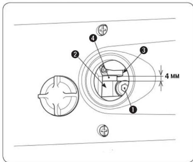
1)Ocna6bTe BnHT 1
2)Pepemecnte 2BpeepnHaHa3a.OTHOWeHneMeKny HAnpaBHeHmE DnXKeHn npa3Mepom nTIN IROJbHoHHTN NOKa3aHO B Ta6nue HnXe.
3) Pocne perynipOBKN, HadeXHO 3aTAHTE BNT
3a3op MeJy KpNBOUHOM 2n ynpbIM KOBuOM 36bln OTperynipobAH Ha 3aOe do 4 MM BO BpeM OTRpy3kn. (BblrpaBnPOBaHHa MapKePHa JINHn Ha oCn KaauoErcn HNTenpTnRaTeJI 4 COBnaJaET C Kpaem KpNBOUHnA 2.)
Pa3mep netnI INIOJIbHOH HHTN
PHONE:(81)42-357-2371
FAX:(81)42-357-2274
http://www.juki.com
Copyright © 2010-2013 JUKI CORPORATION
·本書の内容を無断で軸載、複写するとを禁止いたします。
All rights reserved throughout the world.
- Alle Rechte weltweit vorbehalten.
Tous droits réservés partout dans le monde.
- Reservados todosarethos en el mundo entero.
- Tutti i diritti sono riservati in tutto il mondo.
版权所有,严禁擅自转载、翻印本书的内容。
- Dünya genelinde tüm haklari saklidir.
Bce npaba ydepkaHb BCem Mnppe.
此製品的使方中不明点加有求之販店又当社常業所可合如
Please do not hesitate to contact our distributors or agents in your area for further information when necessary. * The description covered in this instruction manual is subject to change for improvement of the commodity without notice.