
LU1565N - Sewing machine JUKI - Free user manual and instructions
Find the device manual for free LU1565N JUKI in PDF.
Questions des utilisateurs sur LU1565N JUKI
0 question sur cet appareil. Repondez a celles que vous connaissez ou posez la votre.
Poser une nouvelle question sur cet appareil
Download the instructions for your Sewing machine in PDF format for free! Find your manual LU1565N - JUKI and take your electronic device back in hand. On this page are published all the documents necessary for the use of your device. LU1565N by JUKI.
USER MANUAL LU1565N JUKI
ミシン操作中、釜は高速で回転しています。手への損傷防止のため、運転中は釜付近 へ絶対に手を近づけないでください。また、ボビン交換の時は電源を切ってください。 7.不意の起動による事故防止のため、電源の切り忘れに注意してください。 8.本製品は精密機器のため、水や油をかけたり、落下させるなどの衝撃を与えないよ うに、取扱いには十分注意してください。 9.ミシンを倒す時、また元の位置へ戻す時、指等をはさまないよう両手で頭部上側を 持ち、静かに行ってください。vi For the sewing machine, automatic machine and ancillary devices (hereinafter collectively referred to as "machine"), it is inevitable to conduct sewing work near moving parts of the machine. This means that there is always a possibility of unintentionally coming in contact with the moving parts. Operators who actually operate the machine and maintenance personnel who are involved in maintenance and repair of the machine are strongly recommended to carefully read to fully understand the following SAFETY PRECAUTIONS before using/maintaining the machine. The content of the SAFETY PRECAUTIONS includes items which are not contained in the speci¿cations of your product. The risk indications are classi¿ed into the following three different categories to help understand the meaning of the labels. Be sure to fully understand the following description and strictly observe the instructions. Warning label
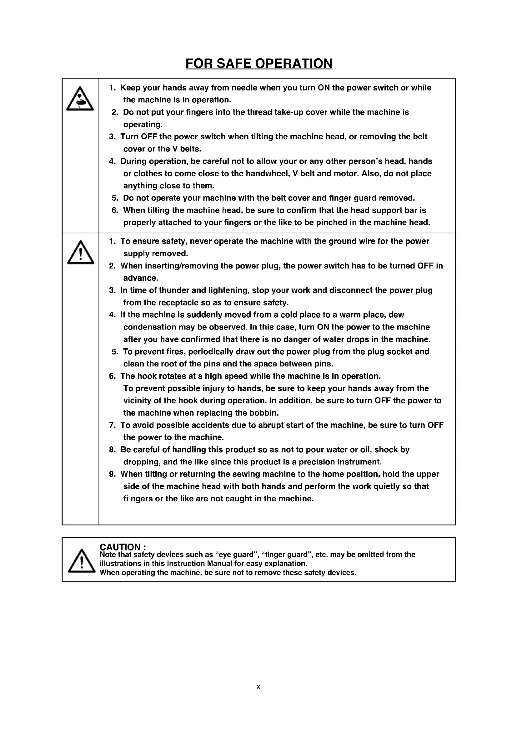
1. To ensure safety, never operate the machine with the ground wire for the power
2. When inserting/removing the power plug, the power switch has to be turned OFF in
3. In time of thunder and lightening, stop your work and disconnect the power plug
from the receptacle so as to ensure safety.
4. If the machine is suddenly moved from a cold place to a warm place, dew
condensation may be observed. In this case, turn ON the power to the machine after you have confi rmed that there is no danger of water drops in the machine.
5. To prevent fi res, periodically draw out the power plug from the plug socket and
clean the root of the pins and the space between pins.
6. The hook rotates at a high speed while the machine is in operation.
To prevent possible injury to hands, be sure to keep your hands away from the vicinity of the hook during operation. In addition, be sure to turn OFF the power to the machine when replacing the bobbin.
7. To avoid possible accidents due to abrupt start of the machine, be sure to turn OFF
the power to the machine.
8. Be careful of handling this product so as not to pour water or oil, shock by
dropping, and the like since this product is a precision instrument.
9. When tilting or returning the sewing machine to the home position, hold the upper
side of the machine head with both hands and perform the work quietly so that fi ngers or the like are not caught in the machine. CAUTION : Note that safety devices such as “eye guard”, “fi nger guard”, etc. may be omitted from the illustrations in this Instruction Manual for easy explanation. When operating the machine, be sure not to remove these safety devices.
1. Keep your hands away from needle when you turn ON the power switch or while
the machine is in operation.
2. Do not put your fi ngers into the thread take-up cover while the machine is
3. Turn OFF the power switch when tilting the machine head, or removing the belt
cover or the V belts.
4. During operation, be careful not to allow your or any other person’s head, hands
or clothes to come close to the handwheel, V belt and motor. Also, do not place anything close to them.
5. Do not operate your machine with the belt cover and fi nger guard removed.
6. When tilting the machine head, be sure to confi rm that the head support bar is
properly attached to your fi ngers or the like to be pinched in the machine head.xi ENGLISH DECLARATION OF INCORPORATION OF PARTLY COMPLETED MACHINERY We hereby declare that the sewing machine (sewing head) described below ;
1. Must not be put into service until the machinery to which it is incorporated has been declared in
conformity with the provisions of the Directive 2006/42/EC, and
2. Conforms to the essential requirements of the Directive 2006/42/EC, described in the technical
3. To be prepared with the above technical documentation compiled in accordance with part B of
4. Also to conform to the RoHS Directive 2011/65/EU
5. Relevant information on which should be transmitted in response to a reasoned request by the
national authorities, by the electronic method or other according to the request. Applied harmonized standards, in particular :
%HL%HUKUXQJHLQHVKHLHQ7HLOV
QDTXHKD\DVLGRPRGL¿FDGDRDOWHUDGD
7HPSHUDWXUDGHOODPELHQWHRSHUDWLYR GDL&DL&
! ᇖ࿏෯֤སఝ֬ןᆣ! ࢝ދഏҊ࢝ഏഽ֬ןᆣ
- Before you put the machine into operation for the fi rst time after the set-up, clean it thoroughly . Remove all dust gathering during transportation and oil it well.
- Confi rm that voltage has been correctly set. Confi rm that the power plug has been properly connected to the power supply.
- Never use the machine in the state where the voltage type is different from the designated one.
- The direction of normal rotation of the machine is counterclockwise as observed from the pulley side. Take care not to allow the machine to rotate in the reverse direction.
- When tilting the machine head, tilt it after removing knee lifter hook.
- Never operate the machine unless the head base has been fi lled with oil.
- For a test run, remove the bobbin and the needle thread.
- For the fi rst month, decrease the sewing speed and run the sewing machine at a speed of 1,600 sti/min or less.
- Operate the handwheel after the machine has totally stopped. CAUTION : Check the following so as to prevent maloperation of and damage to the machine.– 2 –
) at the workstation : A-weighted value of 86.5 dB ; (Includes K
A-weighted value of 91.5 dB; (Includes K
1) Carry the sewing machine with two persons.
(Caution) Do not hold the handwheel.
Do not put protruding articles such as the screwdriver and the like at the location where the sewing machine is placed.
3) Attaching the hinge seats and the support rubbers of the machine head
and the support rubbers
supplied with the machine on the table using nails
If the slide plate comes in contact with the table when opening it, place spacer rubbers
supplied with the machine under support rubbers
4) Attaching the oil pan
supplied with the machine by tighten- ing eight wood screws.
5) Attaching the oil reservoir
Fix the oil reservoir supplied with the machine on the four corners of the table using nails.
into the opening in the machine bed, and fi t the machine head to table rubber hinge before placing the machine head on rubber seats on the four corners.
to the oil pan. Attach packing
and fi x them with nut
7) After they are fi xed, screw in waste oil container
10) Adjust knee pad joint
and assemble these components.
11) Adjust the direction of the pad with setscrews
9) Securely attach head support rod
to the table until it goes no further.
to the screw hole in the arm.
Fix belt cover (right)
on the arm with screws
3) Fit belt cover (left)
of the belt cover (right).
4) Fix belt cover (left)
5) Fix belt cover auxiliary plate
at the position of 10 mm from the rear end with wood screws
when there is a clearance of 2.5 mm between the belt cover and the auxiliary plate.
and move the belt cover auxiliary plate in the direction of the arrow until it stops. Then, tilt the machine head. (Caution) After attaching the belt cover, confi rm whether or not the respective cords do not come in contact with the belt and the handwheel. Disconnection of the cords will result when they come in contact with one another.
Assemble the thread stand, set it up on the machine table using the installation hole in the table and tighten nut
with an appropriate amount of oil before operating the machine once a day. 2) Before you put the machine into operation for the fi rst time after the set-up, or after an extended period of disuse, fi ll the places shown with arrow marks with an appropriate amount of oil.
You can apply oil to the point marked with
after removing the rubber cap without removing the face plate. (Caution) If oil is fi lled more than required, oil leakage may result.
and fi ll the oil reservoir with oil so that the oil surface is higher by 1 mm than the upper surface of the sponge. Necessary amount of oil is approximately 500 cc. (Oil may overfl ow from the oil reservoir when it is poured at a time. So, be careful.)
4) Adjustment of the amount of oil in the hook is performed with oil amount adjustment screw
Turning the oil amount adjustment screw clockwise
will increase the amount of oil in the hook, or counterclockwise
5) The appropriate amount of oil, when a sheet of paper is placed near the periphery of the hook, is to such an extent
that splashes of oil from the hook appear in approximately fi ve seconds as shown in the fi gure.
1) Turn the handwheel to bring the needle bar to the
highest position of its stroke.
2) Loosen needle clamp screws
so that the long grooves in the needles come inside respectively.
deep into the needle clamp holes until they will go no further.
4) Tighten needle clamp screws
fi rmly. (Caution) When replacing the needle, check the clear- ance provided between the needle and the blade point of hook. (Refer to “17. NEEDLE-TO-HOOK RELA- TION” and “18. ADJUSTING THE HOOK NEEDLE GUARD”.) If there is no clearance, the needle and the hook will be damaged.
of hook, and take out the bobbin.
2) Put the bobbin into the shaft in the hook correctly and
release the latch. (Caution) Do not make the machine run idle with the bobbin (bobbin thread). The bobbin thread is caught in the hook. As a result, the hook may be damaged.
/ ATTACHING AND REMOVING THE BOBBIN /
1) Holding the bobbin so that the thread winds clockwise,
fi t it in the bobbin case.
2) Pass the thread in threading slit
in the bobbin case and draw it to route it under the tension spring.
3) Pass the thread drawn from under the tension spring in threading slit
, and further pass it in threading slit
5) Then, pass the thread through hole
to the top cover with setscrew
2) Adjust the position of the thread guide referring to “10.
into the machine arm.
1) Pass the thread in the order of
Then, wind it several turns round the bobbin.
and adjust the position of the ad- justing plate to wind a bobbin about 80 % of its capac- ity.
4) If the bobbin is wound unevenly, correct it by moving
back or forth. Then, tighten setscrews
automatically releases the bobbin and the bobbin winder stops running.
to the top cover with setscrew
2. Pass the left-hand needle thread in the order of
Pass the right-hand needle thread in the order of
as illustrated in the fi gure.
counterclockwise (clockwise) so that the number corresponding to the desired stitch length is brought to the top until the marking spot is reached. (1) Reverse feed stitching
1) Press down reverse feed control lever
2) Reverse feed stitches are made as long as you keep
pressing the lever down.
3) Release the lever, and the machine will run in the nor-
to in- crease the needle thread tension, or counterclockwise
to in- crease the bobbin thread tension, or counterclockwise
(1) To change the stroke of the thread take-up spring
1) For thread take-up spring
to the right or left.
2) For thread take-up spring
on the right-hand side, loosen stopper screw
to the right or left.
3) Move the stopper to the right to increase the stroke or to the left to decrease it.
(2) To change the tension of the thread take-up spring
1) For the thread take-up spring on the left-hand side, loosen nut
and turn spring shaft
counterclockwise to in- crease the tension of the thread take-up spring or clockwise to decrease it.
2) For the thread take-up spring on the right-hand side, loosen screw
and turn thread take-up spring peg
1) When you want to keep the presser foot in the lifted
position, lift hand lifter
in the direction of the arrow. This makes the presser foot rise 9 mm and stay at that position.
2) To make the presser foot come down to its home posi-
1) Turn presser spring regulating dial
increase the pressure of the presser foot, or counter- clockwise
to decrease it. (Note) Be sure to operate the sewing machine with the pressure of the presser foot minimized as long as the presser foot securely holds the material.
1) Set the stitch dial to 0 [zero].
, and give a turn to needle clamp
(adjustment amount : 0.6 mm), or remove spring shoe setscrew
and give a half turn to spring shoe
(adjustment amount : 0.3 mm) to adjust so that the distance from the upper end of needle eyelet of needle
of the hook is 2.8 mm when the needle bar is raised by 1.8 mm from the lowest position of its stroke.
in the screw gear (large) and turn the handwheel to make the needle bar ascend by 1.8 mm from the lowest position of its stroke.
in the hook driving shaft saddle and move the hook driving shaft saddle to the right or left until a clearance of 0.05 to 0.15 mm is provided between the blade point of the hook and the needle at the position where blade point
of the hook is almost aligned with the center of needle
. After the adjustment, tighten setscrews
5) Move the screw gear (large) to the right or left until blade point
of the hook is aligned with the center of needle
and tighten four setscrews
. However, fi t the setscrew No. 1 of setscrews
to the fl at section of the hook driving shaft and tighten it. (Note) When replacing the hook, tighten four setscrews
in the screw gear (small) fi rst. However, fi t the set- screw No. 1 which is “V” shaped at the top end of setscrews
to the “V” groove in the hook shaft and tighten it.
must push the side face of needle
to lean the needle by 0.1 to 0.2 mm away from its straight position. If not, adjust the hook needle guard by bending it.
1) To bend the hook needle guard inward, apply a screwdriver to the outside of the hook needle guard.
2) To bend the hook needle guard outward, apply a screwdriver to the inside of the hook needle guard.
1) Turn the handwheel in its normal rotational direction
to bring bobbin case opening lever
to its back end position.
in the direction of the arrow until bobbin case stopper
rests in the groove in throat plate
in the bobbin case opening lever and adjust so that a clearance of 0.1 to 0.3 mm is provided between the bobbin case opening lever and protruding section
upward in the range of the slot. To decrease it, move the upper feed arm downward. Then, tighten the nut
To change the lifting amount of the presser foot and that of the walking foot, loosen screw
in the upper feed arm, turn the handwheel to this side and tighten screw
when the bottom faces of the presser foot and the walking foot are fl ush at the top surface of the throat plate. Then, the lifting amount of the presser foot becomes more than that of the walking foot. Or, turn the handwheel in the reverse direction to increase the lifting amount of the walking foot more than that of the presser foot. You will fi nd upper feed arm
約 3mm Standard of the amount of alternate vertical movement Engraved marker line
Approx. 5 mm Engraved marker line
Approx. 4 mm Engraved marker line
4.8mm(3/16)〜9.5mm(3/8) 2,000sti/min 12.7mm(1/2) 2,000sti/min The maximum sewing speed has been specifi ed in accordance with sewing conditions as shown in the table below. Set the maximum sewing speed appropriately in accordance with the sewing conditions given taking care not to exceed the corresponding specifi ed value.
1) Maximum sewing speed in accordance with the amount of alternate vertical movement of the walking foot and
presser foot Amount of alternate vertical movement of the walking foot and presser foot Stitch length : 6 mm or less Stitch length : More than 6 mm and 9 mm or less Less than 4 mm 2,000 sti/min 2,000 sti/min 4 mm to less than 6.5 mm 1,600 sti/min 1,600 sti/min
2) Maximum sewing speed in accordance with the needle gauge
Needle gauge Max. sewing speed
4.8 mm (3/16) to 9.5 mm (3/8) 2,000 sti/min
戻っていることを確認してください。 The safety clutch functions when an excessive load is applied to the hook or the other components during sewing. At this time, the hook will never rotate even if turning the handwheel. When the safety clutch has functioned, remove the cause and reset the safety clutch as given in the following procedure.
located on the top surface of the machine bed, strongly turn the handwheel in the reverse direction of rotation.
2) The resetting procedure completes when the handwheel clicks.
(Caution) Turn the handwheel by hand, and confi rm that push button
1– 49 – (1) Stop of the needle bars (right and left) If change-over lever
to moved to position L, the left needle bar will stop. If the lever is moved to position R, the right needle bar will stop. (2) To restore the 2-needle operation Press change-over fi xing lever
will return to the 0 (zero) position to restore the 2-needle sewing mode. (Caution) 1. If you turn the sewing product on the machine to the left or the right for the corner sewing, do not turn it when the needle bar goes up 2 mm from the lowest position of its stroke. If your turn it there, stitch skipping will occur at the corner.
2. If the turning angle of the sewing product is 40° or less, the thread take-up amount of the bob-
Troubles Causes Corrective measures
(Thread frays or is worn out.) (Needle thread trails 2 to 3 cm from the wrong side of the fabric.)
Thread path, needle point, hook blade point or bobbin case resting groove on the throat plate has sharp edges or burrs.
Needle thread tension is too high.
Bobbin case opening lever provides an excessive clearance at the bobbin case.
Needle comes in contact with the blade point of hook.
Amount of oil in the hook is too small.
Needle thread tension is too low.
Thread take-up spring works excessively or the stroke of the spring is too small.
Timing between the needle and the hook is excessively advanced or retarded.
Decrease the needle thread tension.
Decrease the clearance provided be- tween the bobbin case opening lever and the bobbin. Refer to “19. ADJUSTING THE BOB- BIN CASE OPENING LEVER”.
Adjust the amount of oil in the hook properly. Refer to “5. LUBRICATION”.
Increase the needle thread tension.
Decrease the tension of the spring and increase the stroke of the spring.
Timing between the needle and the hook is excessively advanced or retarded.
Pressure of the presser foot is too low.
The clearance provided between the top end of the needle eyelet and the blade point of hook is not correct.
Hook needle guard is not functional.
Improper type of needle is used.
Tighten the presser spring regulator.
Replace the needle with one which is thicker than the current needle by one count.
Bobbin thread does not pass through the tension spring of the inner hook.
Thread path has been poorly fi nished.
Bobbin fails to move smoothly.
Bobbin case opening lever provides too much clearance at the bobbin.
Bobbin thread tension is too low.
Bobbin has been wound too tightly.
Thread the bobbin thread correctly.
Remove rough parts with a fi ne emery paper or buff it up.
Replace the bobbin or hook with a new one.
Refer to “19. ADJUSTING THE BOB- BIN CASE OPENING LEVER”.
Increase the bobbin thread tension.
Decrease the tension applied to the bobbin winder.– 53 –
- All rights reserved throughout the world.