MH484 - Sewing machine JUKI - Free user manual and instructions
Find the device manual for free MH484 JUKI in PDF.
| Product Type | Industrial Sewing Machine |
| Brand | JUKI |
| Model | MH484 |
| Stitch Type | Double Chainstitch, 1 Needle |
| Differential Feed | Yes |
| Maximum Sewing Speed | 5,500 sti/min |
| Stitch Length | 1 to 4 mm (main feed) |
| Differential Feed Ratio | Max extension stitch 1:0.5 / Max gathering stitch 1:3.0 / Standard 1:1.5 |
| Presser Foot Lift Height | Manual: 5 mm / Knee lifter: 10 mm |
| Needle Bar Stroke | 30 mm |
| Recommended Needle | TV ×7, No.9 to No.18 (Standard No.11) |
| Stitch Length Adjustment Method | Dial Type |
| Looper Mechanism | Inclined Crank Type |
| Looper Stroke | 21.5 mm |
| Lubrication System | Fully automatic, JUKI New Defrix Oil No.1 |
| Sound Pressure Level (LpA) | 88.5 dB(A) (KpA=2.5 dB) per ISO 10821 |
| Sound Power Level (LwA) | 94.0 dB(A) (KwA=2.5 dB) per ISO 10821 |
| Motor Power Supply | 400 W, three-phase, 50/60 Hz |
| Safety Devices | Belt cover, finger guard, emergency stop (switch) |
| Special Functions | Reverse stitching, automatic thread trimmer (models -4/-5), gathering stitching (with accessories S060/S061) |
| Maintenance | Regular cleaning of feed dogs, oil drain, oil level check |
| Operating Ambient Temperature | 5 to 35 °C |
| Operating Relative Humidity | 35 to 85% |
| Weight | Approx. 60 kg (machine only estimate) |
Frequently Asked Questions - MH484 JUKI
User questions about MH484 JUKI
0 question about this device. Answer the ones you know or ask your own.
Ask a new question about this device
Download the instructions for your Sewing machine in PDF format for free! Find your manual MH484 - JUKI and take your electronic device back in hand. On this page are published all the documents necessary for the use of your device. MH484 by JUKI.
USER MANUAL MH484 JUKI
TO ENSURE SAFE USE OF YOUR SEWING MACHINE
For the sewing machine, automatic machine and ancillary devices (hereinafter collectively referred to as "machine"), it is inevitable to conduct sewing work near moving parts of the machine. This means that there is always a possibility of unintentionally coming in contact with the moving parts. Operators who actually operate the machine and maintenance personnel who are involved in maintenance and repair of the machine are strongly recommended to carefully read to fully understand the following SAFETY PRECAUTIONS before using/maintaining the machine. The content of the SAFETY PRECAUTIONS includes items which are not contained in the specifications of your product.
The risk indications are classified into the following three different categories to help understand the meaning of the labels. Be sure to fully understand the following description and strictly observe the instructions.
( I ) Explanation of risk levels
| [D87X6] | DANGER:This indication is given where there is an immediate danger of death or serous injury if the person in charge or any third party mishandles the machine or does not avoid the dangerous situation when operating or maintaining the machine. |
 | WARNING:This indication is given where there is a potentiality for death or serious injury if the person in charge or any third party mishandles the machine or does not avoid the dangerous situation when operating or maintaining the machine. |
 | CAUTION:This indication is given where there is a danger of medium to minor injury if the person in charge or any third party mishandles the machine or does not avoid the dangerous situation when operating or maintaining the machine. |
 | Items requiring special attention. |
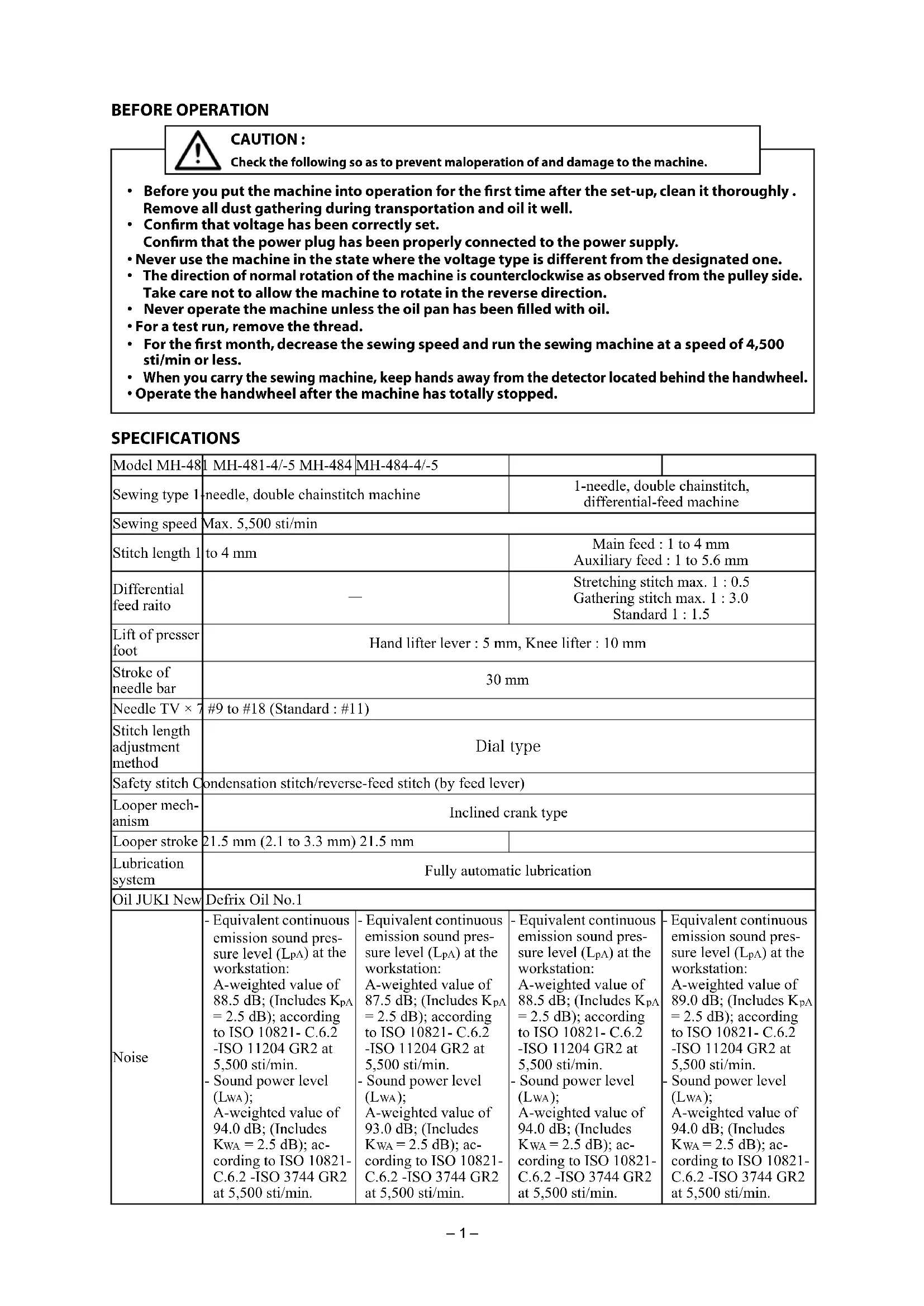
(II) Explanation of pictorial warning indications and warning labels
| Pictorial warning indication |  | There is a risk of injury if contact-ing a moving section. | Pictorial warning indication | Be aware that holding the sewing machine during operation can hurt your hands. | |
 | There is a risk of electrical shock if contacting a high-voltage section. | There is a risk of entanglement in the belt resulting in injury. | |||
 | There is a risk of a burn if contact-ing a high-temperature section. | There is a risk of injury if you touch the button carrier. | |||
 | Be aware that eye deficiency can be caused by looking directly at the laser beam. | Indication label | The correct direction is indicated. | ||
 | There is a risk of contact between your head and the sewing ma-chine. | Connection of a earth cable is indicated. |


1 • There is the possibility that slight to serious injury or death may be caused.
- There is the possibility that injury may be caused by touching moving part.
② • To perform sewing work with safety guard.
• To perform sewing work with safety cover.
- To perform sewing work with safety protection device.
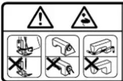
③ • Be sure to turn the power OFF before carrying out "machine-head threading", "needle changing", "bobbin changing" or "cleaning".


Hazardous voltage will cause injury.
Turn off main switch and unplug power cord and wait at least 5 minutes before opening this cover.

DANGER
- When it is necessary to open the control box containing electrical parts, be sure to turn the power off and wait for five minutes or more before opening the cover in order to prevent accident leading to electrical shock.

CAUTION
Basic precaution
- Be sure to read the instruction manual and other explanatory documents supplied with accessories of the machine before using the machine. Carefully keep the instruction manual and the explanatory documents at hand for quick reference.
- The content of this section includes items which are not contained in the specifications of your product.
- Be sure to wear safety goggles to protect against accident caused by needle breakage.
- Those who use a heart pacer have to use the machine after consultation with a medical specialist.
Safety devices and warning labels
- Be sure to operate the machine after verifying that safety device(s) is correctly installed in place and works normally in order to prevent accident caused by lack of the device(s).
- If any of the safety devices is removed, be sure to replace it and verify that it works normally in order to prevent accident that can result in personal injury or death.
- Be sure to keep the warning labels adhered on the machine clearly visible in order to prevent accident that can result in personal injury or death. If any of the labels has stained or come unstuck, be sure to change it with a new one.
Application and modification
- Never use the machine for any application other than its intended one and in any manner other than that prescribed in the instruction manual in order to prevent accident that can result in personal injury or death. JUKI assumes no responsibility for damages or personal injury or death resulting from the use of the machine for any application other than the intended one.
- Never modify and alter the machine in order to prevent accident that can result in personal injury or death. JUKI assumes no responsibility for damages or personal injury or death resulting from the machine which has been modified or altered.
Education and training
- In order to prevent accident resulting from unfamiliarity with the machine, the machine has to be used only by the operator who has been trained/educated by the employer with respect to the machine operation and how to operate the machine with safety to acquire adequate knowledge and operation skill. To ensure the above, the employer has to establish an education/training plan for the operators and educate/train them beforehand.
Items for which the power to the machine has to be turned off
Turning the power off: Turning the power switch off, then removing the power plug from the outlet. This applies to the following.
- Be sure to immediately turn the power off if any abnormality or failure is found or in the case of power failure in order to protect against accident that can result in personal injury or death.
- To protect against accident resulting from abrupt start of the machine, be sure to carry out the following operations after turning the power off. For the machine incorporating a clutch motor, in particular, be sure to carry out the following operations after turning the power off and verifying that the machine stops completely.
2-1. For example, threading the parts such as the needle, looper, spreader etc. which have to be threaded, or changing the bobbin.
2-2. For example, changing or adjusting all component parts of the machine.
2-3. For example, when inspecting, repairing or cleaning the machine or leaving the machine.
-
Be sure to remove the power plug by holding the plug section instead of the cord section in order to prevent electrical-shock, earth-leakage or fire accident.
-
Be sure to turn the power off whenever the machine is left unattended between works.
-
Be sure to turn the power off in the case of power failure in order to prevent accident resulting of breakage of electrical components.
PRECAUTIONS TO BE TAKEN IN VARIOUS OPERATION STAGES
Transportation
- Be sure to lift and move the machine in a safe manner taking the machine weight in consideration. Refer to the text of the instruction manual for the mass of the machine.
- Be sure to take sufficient safety measures to prevent falling or dropping before lifting or moving the machine in order to protect against accident that can result in personal injury or death.
- Once the machine has been unpacked, never re-pack it for transportation to protect the machine against breakage resulting from unexpected accident or dropping.
Unpacking
- Be sure to unpack the machine in the prescribed order in order to prevent accident that can result in personal injury or death. In the case the machine is crated, in particular, be sure to carefully check nails. The nails have to be removed.
- Be sure to check the machine for the position of its center of gravity and take it out from the package carefully in order to prevent accident that can result in personal injury or death.
Installation
(I) Table and table stand
- Be sure to use JUKI genuine table and table stand in order to prevent accident that can result in personal injury or death. If it is inevitable to use a table and table stand which are not JUKI genuine ones, select the table and table stand which are able to support the machine weight and reaction force during operation.
- If casters are fitted to the table stand, be sure to use the casters with a locking mechanism and lock them to secure the machine during the operation, maintenance, inspection and repair in order to prevent accident that can result in personal injury or death.
(II) Cable and wiring
- Be sure to prevent an extra force from being applied to the cable during the use in order to prevent electrical-shock, earth-leakage or fire accident. In addition, if it is necessary to cable near the operating section such as the V-belt, be sure to provide a space of 30 mm or more between the operating section and the cable.
- Be sure to avoid starburst connection in order to prevent electrical-shock, earth-leakage or fire accident.
- Be sure to securely connect the connectors in order to prevent electrical-shock, earth-leakage or fire accident. In addition, be sure to remove the connector while holding its connector section.
(III) Grounding
- Be sure to have an electrical expert install an appropriate power plug in order to prevent accident caused by earth-leakage or dielectric strength voltage fault. In addition, be sure to connect the power plug to the grounded outlet without exceptions.
- Be sure to ground the earth cable in order to prevent accident caused by earth leakage.
(IV) Motor
- Be sure to use the specified rated motor (JUKI genuine product) in order to prevent accident caused by burnout.
- If a commercially available clutch motor is used with the machine, be sure to select one with an entanglement preventive pulley cover in order to protect against being entangled by the V-belt.
Before operation
- Be sure to make sure that the connectors and cables are free from damage, dropout and looseness before turning the power on in order to prevent accident resulting in personal injury or death.
- Never put your hand into the moving sections of the machine in order to prevent accident that can result in personal injury or death. In addition, check to be sure that the direction of rotation of the pulley agrees with the arrow shown on pulley.
- If the table stand with casters is used, be sure to secure the table stand by locking the casters or with adjusters, if provided, in order to protect against accident caused by abrupt start of the machine.
During operation
- Be sure not to put your fingers, hair or clothing close to the moving sections such as the handwheel, hand pulley and motor or place something near those sections while the machine is in operation in order to prevent accident caused by entanglement that can result in personal injury or death.
- Be sure not to place your fingers near the surround area of the needle or inside the thread take-up lever cover when turning the power on or while the machine is in operation in order to prevent accident that can result in personal injury or death.
- The machine runs at a high speed. Never bring your hands near the moving sections such as looper, spreader, needle bar, hook and cloth trimming knife during operation in order to protect your hands against injury. In addition, be sure to turn the power off and check to be sure that the machine completely stops before changing the thread.
-
Be careful not to allow your fingers or any other parts of your body to be caught between the machine and table when removing the machine from or replacing it on the table in order to prevent accident that can result in personal injury or death.
-
Be sure to turn the power off and check to be sure that the machine and motor completely stop before removing the belt cover and V-belt in order to prevent accident caused by abrupt start of the machine or motor.
-
If a servomotor is used with the machine, the motor does not produce noise while the machine is at rest. Be sure not to forget to turn the power off in order to prevent accident caused by abrupt start of the motor.
-
Never use the machine with the cooling opening of the motor power box shielded in order to prevent fire accident by overheat.
Lubrication
- Be sure to use JUKI genuine oil and JUKI genuine grease to the parts to be lubricated.
- If the oil adheres on your eye or body, be sure to immediately wash it off in order to prevent inflammation or irritation.
- If the oil is swallowed unintentionally, be sure to immediately consult a medical doctor in order to prevent diarrhea or vomiting.
Maintenance
- In prevention of accident caused by unfamiliarity with the machine, repair and adjustment has to be carried out by a service technician who is thoroughly familiar with the machine within the scope defined in the instruction manual. Be sure to use JUKI genuine parts when replacing any of the machine parts. JUKI assumes no responsibility for any accident caused by improper repair or adjustment or the use of any part other than JUKI genuine one.
- In prevention of accident caused by unfamiliarity with the machine or electrical-shock accident, be sure to ask an electrical technician of your company or JUKI or distributor in your area for repair and maintenance (including wiring) of electrical components.
- When carrying out repair or maintenance of the machine which uses air-driven parts such as an air cylinder, be sure to remove the air supply pipe to expel air remaining in the machine beforehand, in order to prevent accident caused by abrupt start of the air-driven parts.
- Be sure to check that screws and nuts are free from looseness after completion of repair, adjustment and part replacement.
- Be sure to periodically clean up the machine during its duration of use. Be sure to turn the power off and verify that the machine and motor stop completely before cleaning the machine in order to prevent accident caused by abrupt start of the machine or motor.
- Be sure to turn the power off and verify that the machine and motor stop completely before carrying out maintenance, inspection or repair of the machine. (For the machine with a clutch motor, the motor will keep running for a while by inertia even after turning the power off. So, be careful.)
- If the machine cannot be normally operated after repair or adjustment, immediately stop operation and contact JUKI or the distributor in your area for repair in order to prevent accident that can result in personal injury or death.
- If the fuse has blown, be sure to turn the power off and eliminate the cause of blowing of the fuse and replace the blown fuse with a new one in order to prevent accident that can result in personal injury or death.
- Be sure to periodically clean up the air vent of the fan and inspect the area around the wiring in order to prevent fire accident of the motor.
Operating environment
- Be sure to use the machine under the environment which is not affected by strong noise source (electromagnetic waves) such as a high-frequency welder in order to prevent accident caused by malfunction of the machine.
- Never operate the machine in any place where the voltage fluctuates by more than "rated voltage ± 10% in order to prevent accident caused by malfunction of the machine.
- Be sure to verify that the air-driven device such as an air cylinder operates at the specified air pressure before using it in order to prevent accident caused by malfunction of the machine.
- To use the machine with safety, be sure to use it under the environment which satisfies the following conditions:
Ambient temperature during operation 5°C to 35°C
Relative humidity during operation 35 % to 85 %
- Dew condensation can occur if bringing the machine suddenly from a cold environment to a warm one. So, be sure to turn the power on after having waited for a sufficient period of time until there is no sign of water droplet in order to prevent accident caused by breakage or malfunction of the electrical components.
- Be sure to stop operation when lightning flashes for the sake of safety and remove the power plug in order to prevent accident caused by breakage or malfunction of the electrical components.
- Depending on the radio wave signal condition, the machine may generate noise in the TV or radio. If this occurs, use the TV or radio with kept well away from the machine.
- In order to ensure the work environment, local laws and regulations in the country where the sewing machine is installed shall be followed. In the case the noise control is necessary, an ear protector or other protective gear should be worn according to the applicable laws and regulations.
- Disposal of products and packages and treatment of used lubricating oil should be carried out properly according to the relevant laws of the country in which the sewing machine is used.
FOR SAFE OPERATION
 | 1. Keep your hands away from needle when you turn ON the power switch or while the machine is in operation.2. Do not put your fingers into the thread take-up cover while the machine is operating.3. Turn OFF the power switch when tilting the machine head, or removing the belt cover or the V belts.4. During operation, be careful not to allow your or any other person's head, hands or clothes to come close to the handwheel, V belt and motor. Also, do not place anything close to them.5. Do not operate your machine with the belt cover and finger guard removed.6. When tilting the machine head, be sure to confirm that the head support bar is properly attached to your machine head, and be careful not to allow your fingers or the like to be pinched in the machine head. |
 | 1. To ensure safety, never operate the machine with the ground wire for the power supply removed.2. When inserting/removing the power plug, the power switch has to be turned OFF in advance.3. In time of thunder and lightening, stop your work and disconnect the power plug from the receptacle so as to ensure safety.4. If the machine is suddenly moved from a cold place to a warm place, dew condensation may be observed. In this case, turn ON the power to the machine after you have confirmed that there is no danger of water drops in the machine.5. To prevent fires, periodically draw out the power plug from the plug socket and clean the root of the pins and the space between pins.6. The loopers oscillate at a high speed during operation.Be sure to keep your hands away from the vicinity of the loopers to protect hands from possible injury during operation. Turn the power OFF before threading the machine head.7. To avoid possible accidents due to abrupt start of the machine, be sure to turn OFF the power to the machine.8. Be careful of handling this product so as not to pour water or oil, shock by dropping, and the like since this product is a precision instrument.9. When tilting or returning the sewing machine to the home position, hold the upper side of the machine head with both hands and perform the work quietly so that fingers or the like are not caught in the machine. |

CAUTION :
Note that safety devices such as “belt cover”, “finger guard”, etc. may be omitted from the illustrations in this Instruction Manual for easy explanation.
When operating the machine, be sure not to remove these safety devices.
DECLARATION OF INCORPORATION OF PARTLY COMPLETED MACHINERY
We hereby declare that the sewing machine (sewing head) described below ;
- Must not be put into service until the machinery to which it is incorporated has been declared inconformity with the provisions of the Directive 2006/42/EC, and
- Conforms to the essential requirements of the Directive 2006/42/EC, described in the technical documentation, and
- To be prepared with the above technical documentation compiled in accordance with part B of Annex VII, and
- Relevant information on which should be transmitted in response to a reasoned request by the national authorities, by the electronic method or other according to the request.
Model MH-481, MH-481-4, MH-481-5
MH-484, MH-484-4, MH-484-5
Serial No
Description Industrial Sewing Machine
Function make stitches and sew
Applied harmonized standards, in particular :
EN ISO12100-1, EN ISO12100-2, EN ISO10821
Manufacturer :
JUKI CORPORATION
2-11-1, Tsurumaki, Tama-shi, Tokyo, Japan
CONTENTS
Check the following so as to prevent maloperation of and damage to the machine.
- Before you put the machine into operation for the first time after the set-up, clean it thoroughly. Remove all dust gathering during transportation and oil it well.
- Confirm that voltage has been correctly set. Confirm that the power plug has been properly connected to the power supply.
- Never use the machine in the state where the voltage type is different from the designated one.
- The direction of normal rotation of the machine is counterclockwise as observed from the pulley side. Take care not to allow the machine to rotate in the reverse direction.
- Never operate the machine unless the oil pan has been filled with oil.
- For a test run, remove the thread.
- For the first month, decrease the sewing speed and run the sewing machine at a speed of 4,500 sti/min or less.
- When you carry the sewing machine, keep hands away from the detector located behind the handwheel.
- Operate the handwheel after the machine has totally stopped.
SPECIFICATIONS
| Model MH-481 | MH-481-4/-5 MH-484 | MH-484-4/-5 | ||
| Sewing type 1 | -needle, double chainstitch machine | 1-needle, double chainstitch,differential-feed machine | ||
| Sewing speed | Max. 5,500 sti/min | |||
| Stitch length 1 | to 4 mm | Main feed: 1 to 4 mmAuxiliary feed: 1 to 5.6 mm | ||
| Differential feed raito | — | Stretching stitch max. 1: 0.5Gathering stitch max. 1: 3.0Standard 1: 1.5 | ||
| Lift of presser foot | Hand lifter lever: 5 mm, Knee lifter: 10 mm | |||
| Stroke of needle bar | 30 mm | |||
| Needle TV × 7 | #9 to #18 (Standard: #11) | |||
| Stitch length adjustment method | Dial type | |||
| Safety stitch | Condensation stitch/reverse-feed stitch (by feed lever) | |||
| Looper mech-anism | Inclined crank type | |||
| Looper stroke | 21.5 mm (2.1 to 3.3 mm) 21.5 mm | |||
| Lubrication system | Fully automatic lubrication | |||
| Oil JUKI New | Defrix Oil No.1 | |||
| Noise | -Equivalent continuous emission sound pressure level (LpA) at the workstation:A-weighted value of 88.5 dB; (Includes KpA=2.5 dB); according to ISO 10821-C.6.2-ISO 11204 GR2 at 5,500 sti/min.-Sound power level (LwA);A-weighted value of 94.0 dB; (Includes Kwa=2.5 dB); according to ISO 10821-C.6.2 -ISO 3744 GR2 at 5,500 sti/min. | -Equivalent continuous emission sound pressure level (LpA) at the workstation:A-weighted value of 87.5 dB; (Includes KpA=2.5 dB); according to ISO 10821-C.6.2-ISO 11204 GR2 at 5,500 sti/min.-Sound power level (LwA);A-weighted value of 93.0 dB; (Includes Kwa=2.5 dB); according to ISO 10821-C.6.2 -ISO 3744 GR2 at 5,500 sti/min. | -Equivalent continuous emission sound pressure level (LpA) at the workstation:A-weighted value of 88.5 dB; (Includes KpA=2.5 dB); according to ISO 10821-C.6.2-ISO 11204 GR2 at 5,500 sti/min.-Sound power level (LwA);A-weighted value of 94.0 dB; (Includes Kwa = 2.5 dB); according to ISO 10821-C.6.2 -ISO 3744 GR2 at 5,500 sti/min. | -Equivalent continuous emission sound pressure level (LpA) at the workstation:A-weighted value of 89.0 dB; (Includes KpA=2.5 dB); according to ISO 10821-C.6.2-ISO 11204 GR2 at 5,500 sti/min.-Sound power level (LwA);A-weighted value of 94.0 dB; (Includes Kwa = 2.5 dB); according to ISO 10821-C.6.2 -ISO 374 4 GR2 at 5,500 sti/min. |
1. INSTALLATION

1) Carry the sewing machine with two persons.
(Caution) Do not hold the handwheel.
2) Do not put protruding articles such as the screw-driver and the like at the location where the sewing machine is placed.
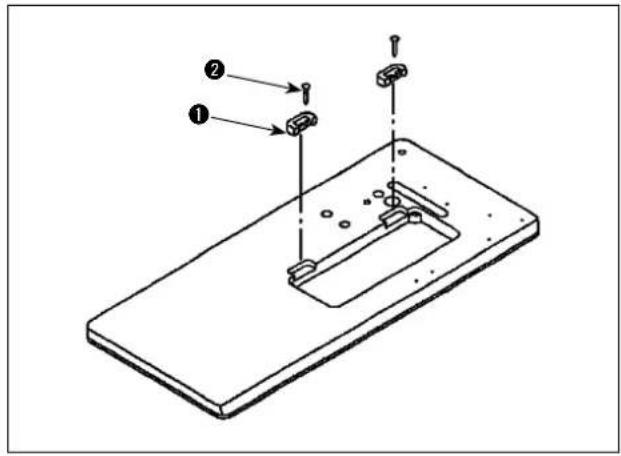
3) Attaching the hinge seats and the support rubbers of the machine head
Fix the hinge seats ① supplied with the machine on the table using nails ②.
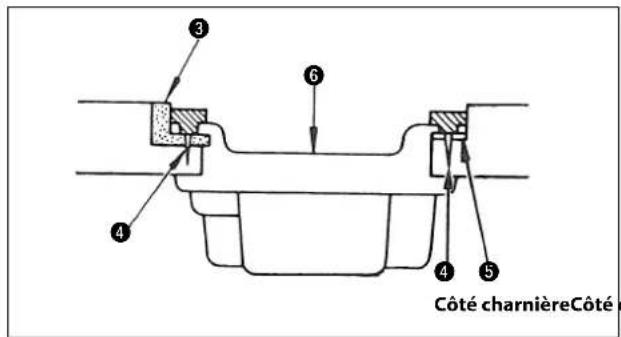
4) Attaching the oil pan
Install the oil reservoir ⑥ in the way that it is supported by four corners of the opening in the table. Nail two rubber cushions ③ to a protruded edge from the table opening at operator's side using nails ④ and also attach two head-rest cushions ⑤ to a protruded edge at the far end (hinge side) using nails ④, and the place oil reservoir ⑥ on the cushions.
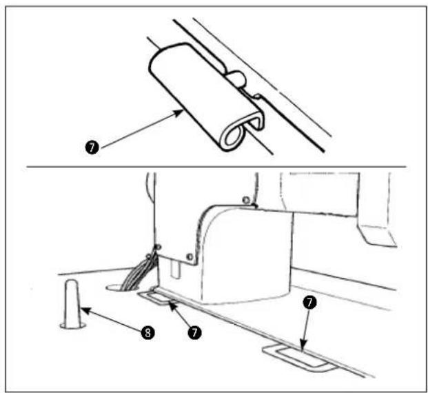
5) Fit hinge⑦ into the opening in the machine bed, and fi t the machine head to table rubber hinge before placing the machine head on rubber seats on the four corners.
6) Securely attach head support rod ⑧ to the table until it goes no further.
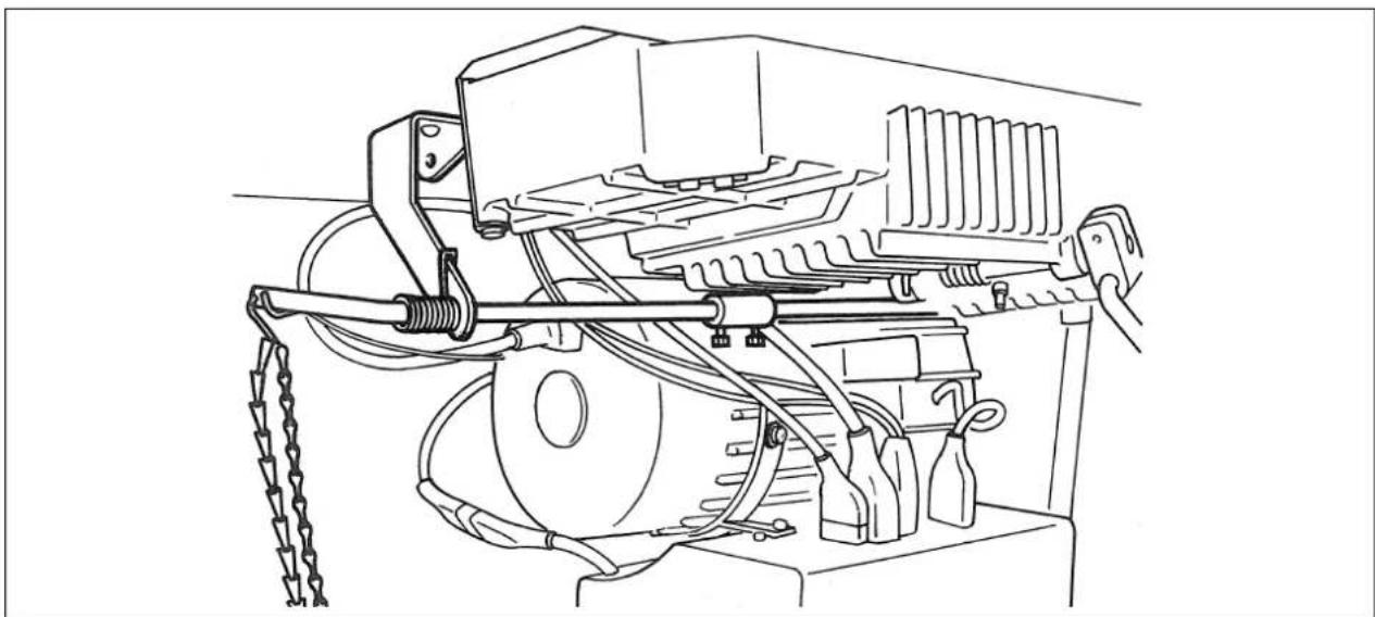
2. ADJUSTING THE BELT TENSION

WARNING :
To avoid possible personal injury due to abrupt start of the machine, turn off the power to the machine and check to be sure that the motor has totally stopped rotating in prior.
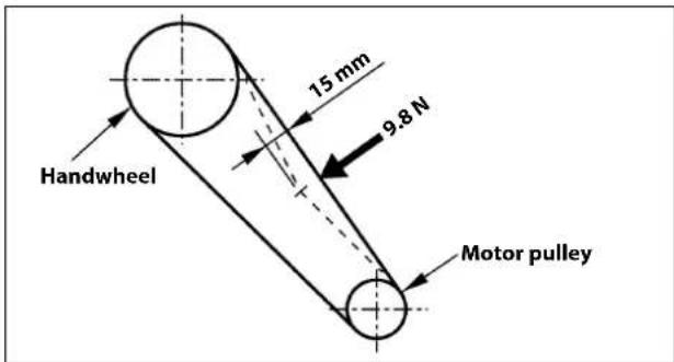
Adjust the belt tension with the height of the motor so that the belt sags 15 mm when the center of V belt is applied with a 9.8 N load.
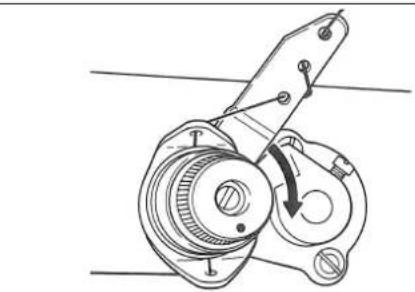
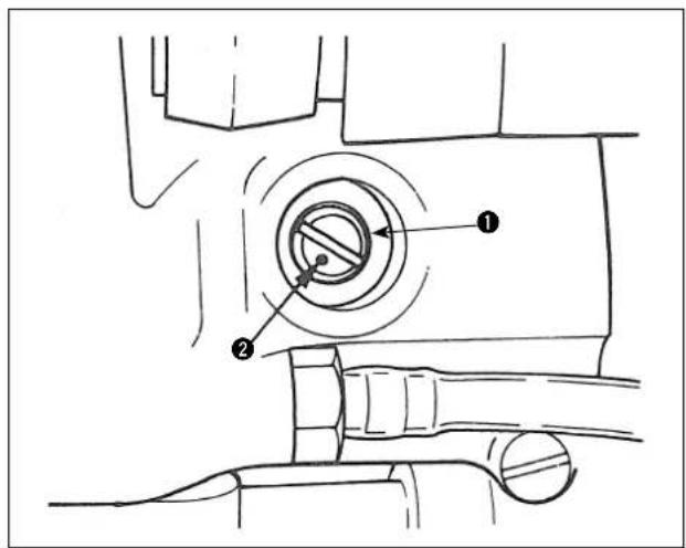
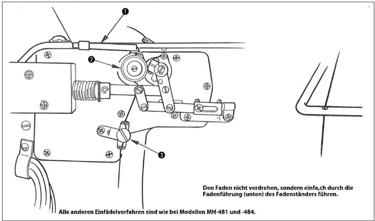
3. INSTALLING THE THREAD STAND
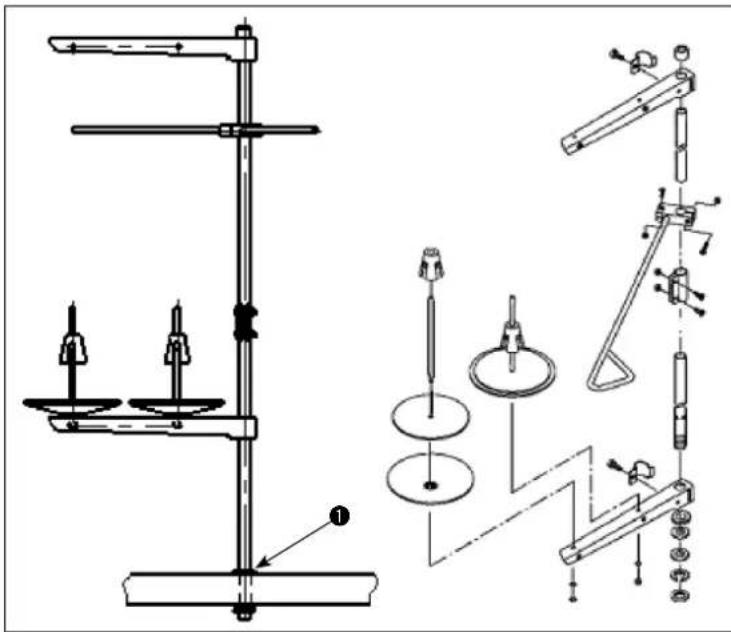
Assemble the thread stand, set it up on the machine table using the installation hole in the table and tighten nut ① gently.
4. LUBRICATION

WARNING : To avoid possible personal injury due to abrupt start of the machine, turn off the power to the machine and check to be sure that the motor has totally stopped rotating in prior.
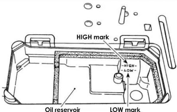
- Before operation, fill the oil reservoir with JUKI New Defrix Oil No.1 up to the HIGH mark.
- Whenever the oil level drops to the LOW mark, add more oil.
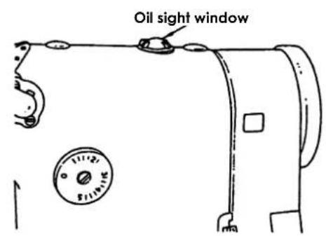
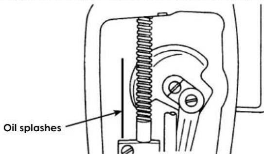
- When the sewing machine is run after the oil reservoir has been filled, oil can be seen splashing on the oil sight window. However, the amount of oil splash has no relation to the amount of oil in the reservoir so there is no need to worry.
- When the oil has become dirty, replace it with fresh oil. Unscrew the oil plug from the oil reservoir when draining.
- When using a new sewing machine or one that has not been used for a long time let it idle for about ten minutes at 3,500 to 4,000 sti/min to run it in.
(Caution) 1. Verify that the lubricating oil is properly circulating by watching it through the oil sight window.
- Remove any fiberous dust from the oil pump filter screen and the oil reservoir.
- When the lubrication oil has become dirty, drain it through the oil drain screw cap and fill it with new JUKI New Defrix Oil No.1.
- Verify that the oil level is above "LOW" mark.
- Clean up the oil reservoir magnet with a cloth.
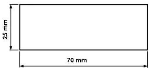
① Amount of oil (oil splashes) confirmation paper

② Position to confirm the amount of oil (oil splashes)
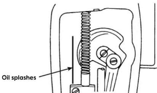
Confirmation of the amount of oil supplied to the face plate parts
1) If the machine has not been sufficiently warmed up for operation, make the machine run idle for approximately three minutes. (Moderate intermittent operation)
2) Place the amount of oil (oil spots) confirmation paper under the hook immediately after the machine stops running.
3) Confirm the height of the oil surface in the oil reservoir is within the range between "HIGH" and "LOW".
4) Confirmation of the amount of oil should be completed in five seconds. (Check the period of time with a watch.)
Minimum oil flow
Maximum oil flow
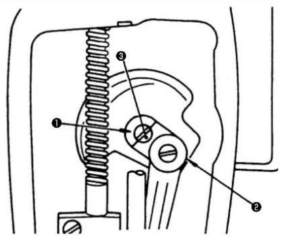
Adjustment of oil amount for the face plate components.
Amount of lubricating oil supplied to the face plate components such as needle bar crank ② is adjustable by turning adjusting pin ①: bring the dot mark ③ engraved on the adjusting pin close to needle bar crank ② to minimize or farthest from the needle bar crank ② to maximize the amount of oil maximize the amount of oil.
(Caution) The oil amount does not change immediately after adjustment, so have this in mind when adjusting the oil amount.
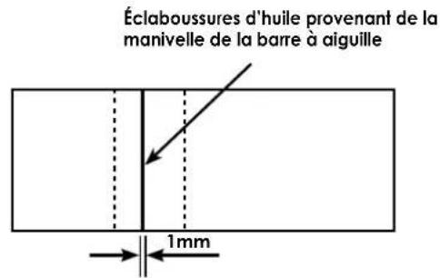
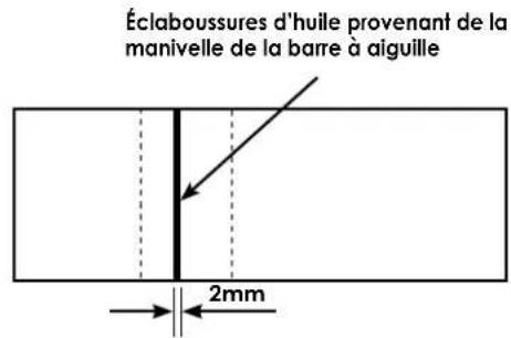
Appropriate amount of oil (small)
Appropriate amount of oil (large)
Oil splashing from the needle bar crank Oil splashing from the needle bar crank
Sample showing the appropriate amount of oil supplied to the face plate parts
1) The state given in the figure shows the appropriate amount of oil (oil splashes). It is necessary to finely adjust the amount of oil in accordance with the sewing processes. However, do not excessively increase/decrease the amount of oil in the hook. (If the amount of oil is too small, the face plate parts will be hot or seize. If the amount of oil is too much, the sewing product may be stained with oil.)
2) Adjust the amount of oil in the hook so that the oil amount (oil splashes) should not change while checking the oil amount three times (on the three sheets of paper).
5. ATTACHING THE BELT COVER

WARNING :
To avoid possible personal injury due to abrupt start of the machine, turn off the power to the machine and check to be sure that the motor has totally stopped rotating in prior.
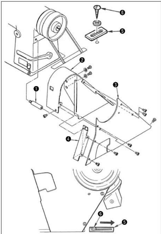
- Insert belt cover support ① into the tapped hole in the machine arm.
- Temporarily fix belt cove② on the machine head with screws.
- Slightly tilting the machine head, put rid ③ of the belt cover inside the outer pulley and fi x rid ③ with four screws.
- Fix rid③ on support ①.
- Loosen the screws in the belt cover, and adjust the position of belt cover ② properly. Then securely tighten the screws in the belt cover.
- Fix bobbin winder cover ④ with three screws.
- Fix belt cover auxiliary plate ⑤ as illustrated in the figure.
(Caution) 1. When tilting the machine, loosen wooden screw ⑥ in belt cover auxiliary plate ⑤ and move the auxiliary plate in the direction of the arrow to such an extent that it does not come in contact with the belt cover as shown in the figure.
- After you have raised the machine, return belt cover auxiliary plate ⑤ to the previous position.
6. ATTACHING THE NEEDLE

WARNING:
To avoid possible personal injury due to abrupt start of the machine, turn off the power to the machine and check to be sure that the motor has totally stopped rotating in prior.
flowchart
graph TD
    A["Circle A"] --> B["Circle B"]
    B --> C["Circle C"]
    style A fill:#fff,stroke:#000
    style B fill:#fff,stroke:#000
    style C fill:#fff,stroke:#000
    note1["Feed direction"] --> A
    note2["Arrow"] --> A
Use a TV×7 needle.
Different needle counts are applicable. However, select an appropriate one according to the thickness of thread and the type of material to be used. (#9 to #21)
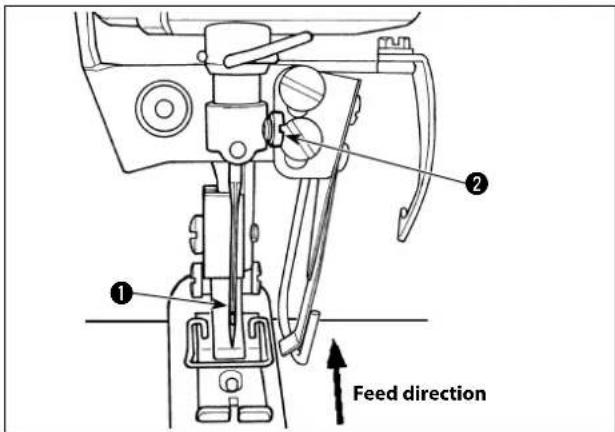
1) Turn the handwheel to bring the needle bar to the highest position of its stroke.
2) Loosen needle clamp screw ②. Hold needle ① so that its scarf faces toward the feeding direction of material.
3) Insert needle① fully into the needle clamp hole until it comes in contact with the deep end.
4) Firmly tighten needle clamp screw ②.
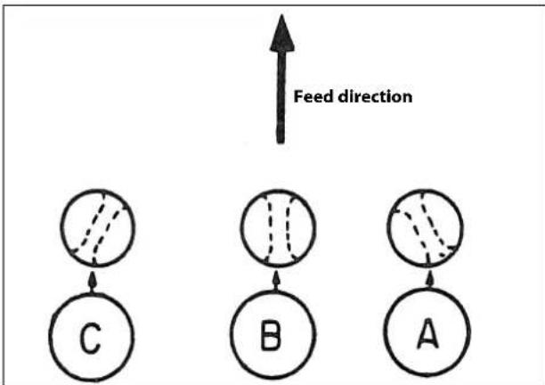
Attach the needle so that its eyelet faces toward A for filament thread, or B for cotton thread so as to prevent stitch skipping of needle thread.
To carry out reverse-feed stitching with consistency, do not allow the needle eyelet to face toward C.
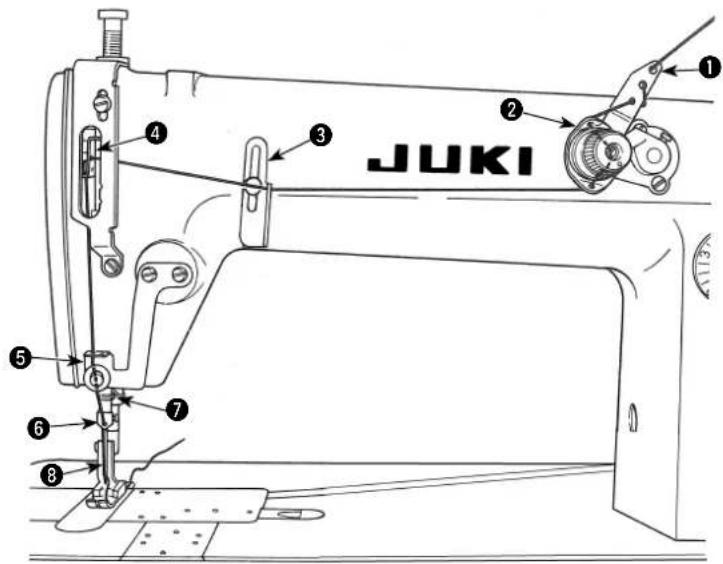
7. THREADING THE MACHINE HEAD

WARNING :
To avoid possible personal injury due to abrupt start of the machine, turn off the power to the machine and check to be sure that the motor has totally stopped rotating in prior.
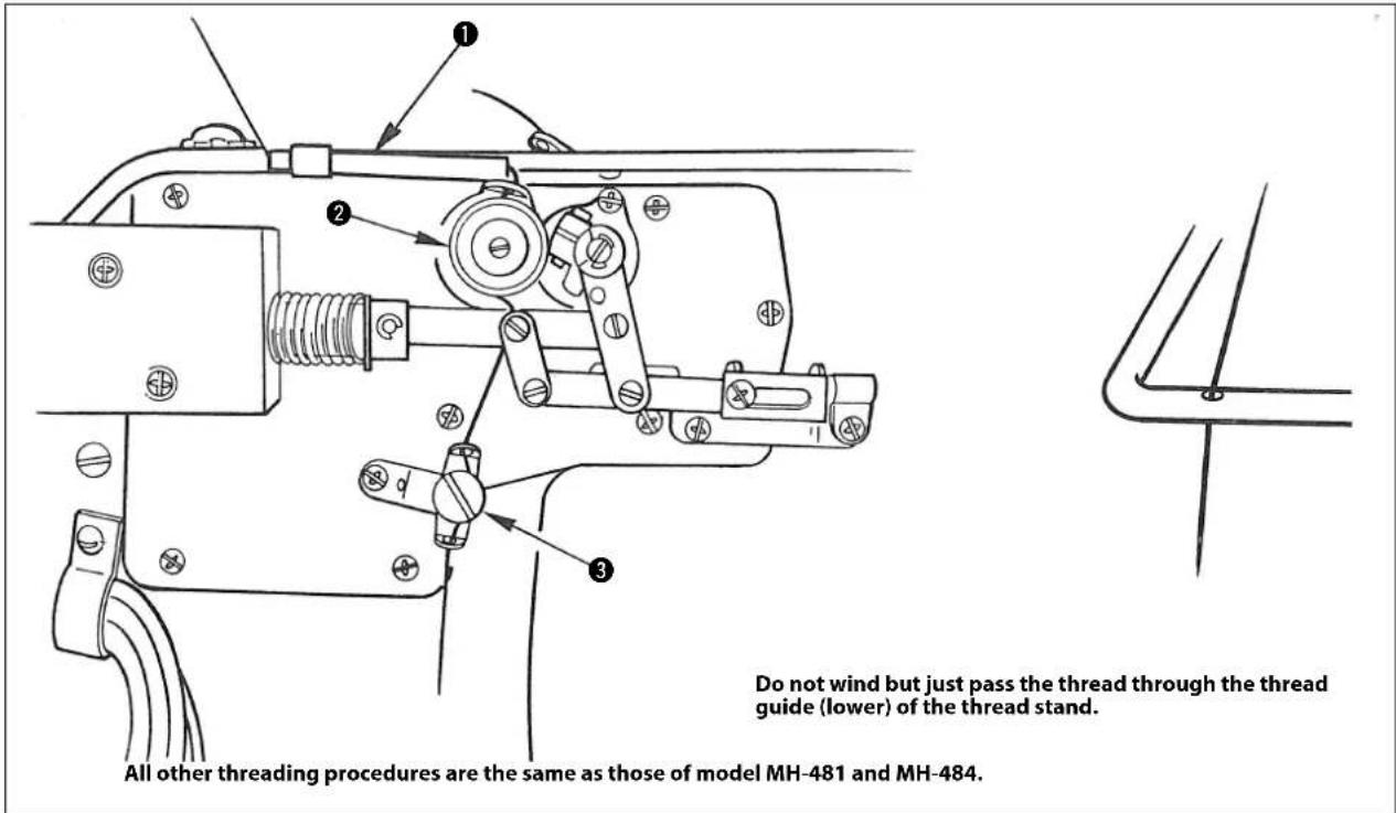
MH-481, MH-484

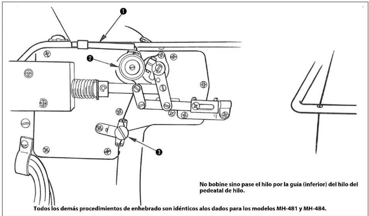
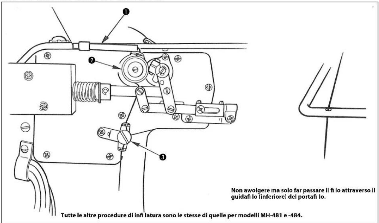
MH-481-4, MH-481-5, MH-484-4, MH-484-5
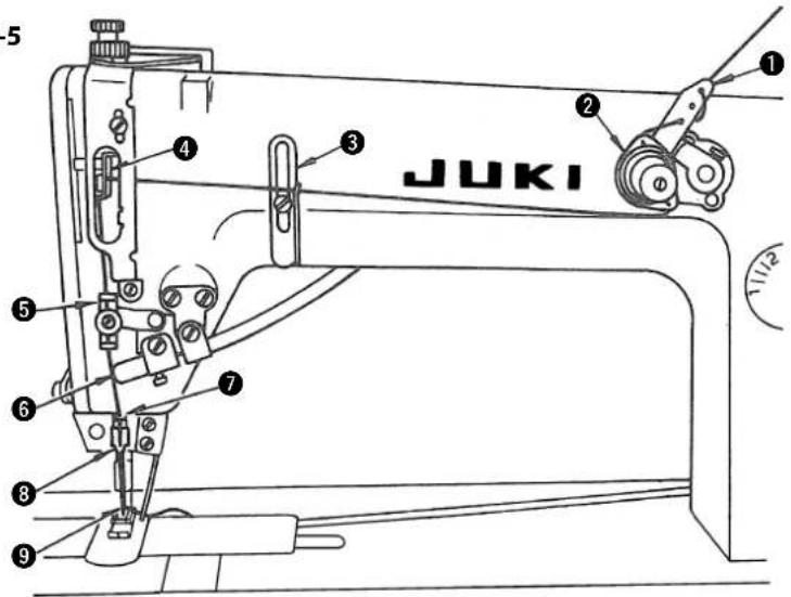
With the needle bar raised to its highest position, pass the thread in the order as shown in the figure.
- Pass the thread to the needle hole toward the opposite side of the operator from the operator side.
- Pull out the thread which was passed through the needle about 10 cm (4").
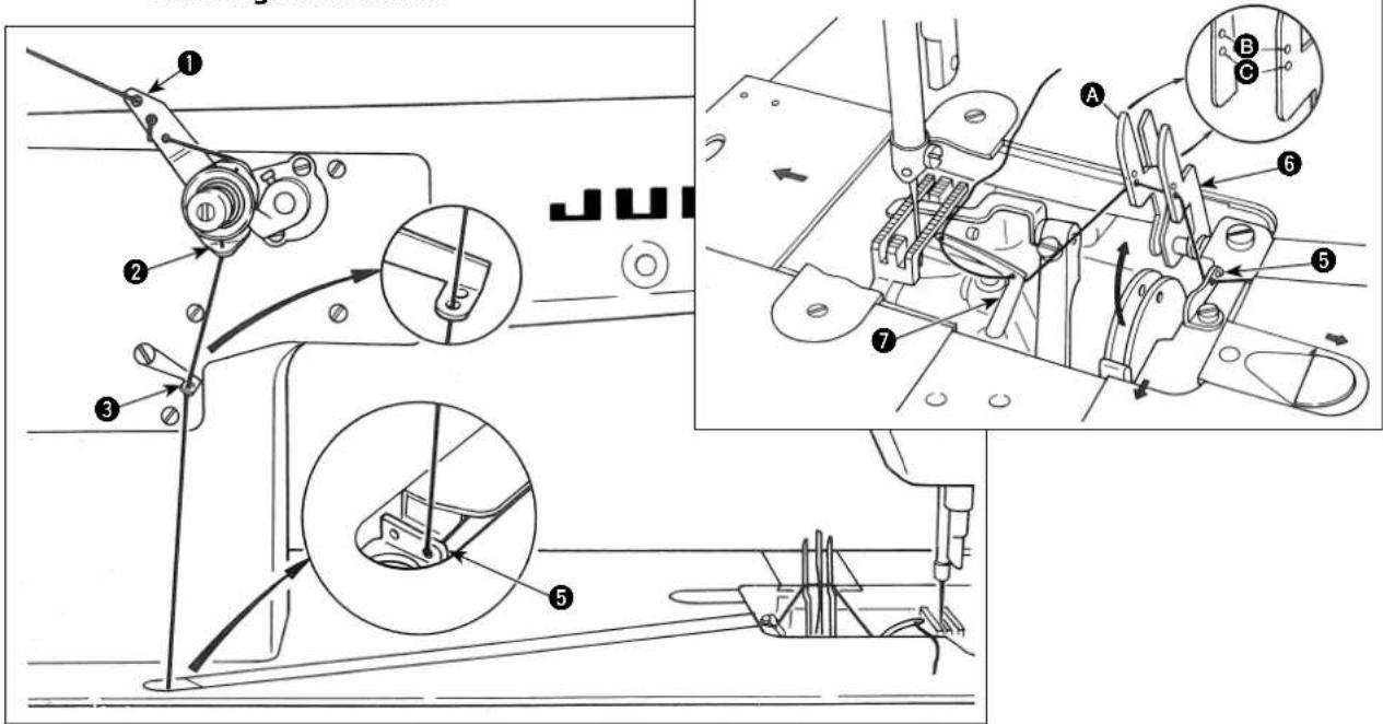
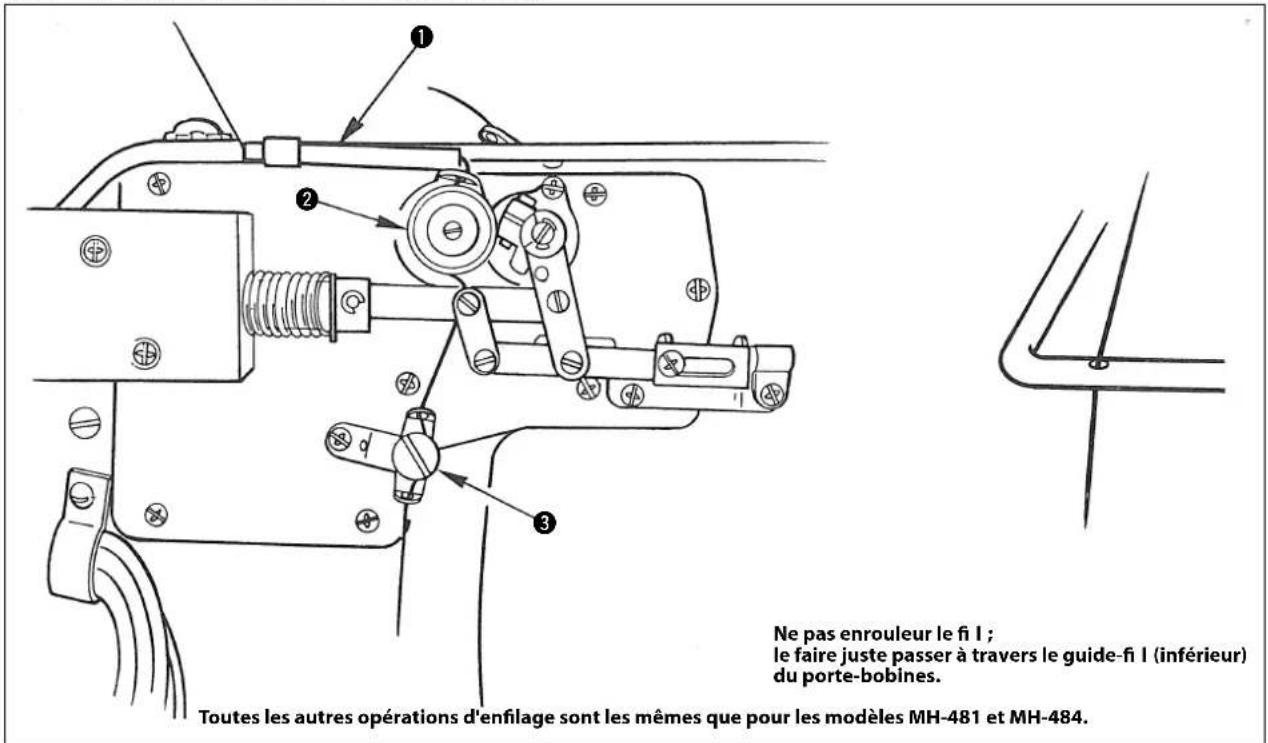
8. THREADING THE LOOPERS

WARNING :
To avoid possible personal injury due to abrupt start of the machine, turn off the power to the machine and check to be sure that the motor has totally stopped rotating in prior.
[MH-481, MH-484]
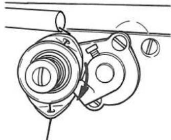
Pass the looper thread as shown in the fi gure.
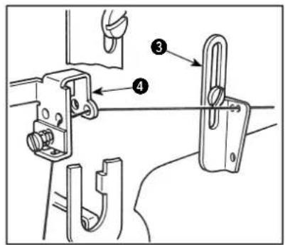
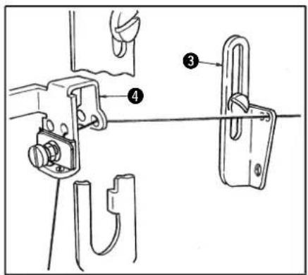
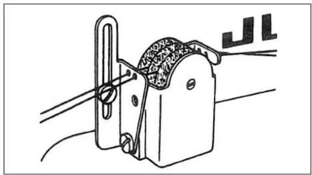
- Pass the looper thread through the looper thread guide plate as illustrated. When using a hard-twisted thread or when sewing with a large feed pitch, pass it through 2 holes to form a loop. When sewing fine materials which tend to pucker, pass the thread through only one hole in order to lessen the thread tension.
- Pull the plate spring in the direction of arrow as shown in the lower figure, and the thread guide A will come up. As the close-up figure shows, the thread guide A has two sets of thread holes; the holes B are used when a stitch is preferably formed with soft looper thread tension, a stretchable thread is used or stitch length is more than 3 mm (1/8"), and the holes C are used when a stitch having a normal thread tension is preferred.
- In passing the thread to the looper, use a tweezer in the accessory box and after passing, pull it out 5 cm (2") from the tip of the looper.
(Caution) Detach the throat plate, bed slide and cam cover and remove any dust from the teeth of the feed dog with a brush.
[MH-481-4, MH-481-5, MH-484-4, MH-484-5]
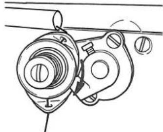
9. THREAD TENSION
natural_image
Mechanical assembly diagram showing a gear mechanism with no visible text or symbolsNeedle thread tension
Rotate to right to make the tension stronger.
[MH-481, MH-484]
natural_image
Technical line drawing of a mechanical assembly with no visible text or symbols[MH-481-4, MH-481-5, MH-484-4, MH-484-5]

natural_image
Technical line drawing of a mechanical assembly with no visible text or symbolsLooper thread tension
Rotate to right to make the tension stronger.
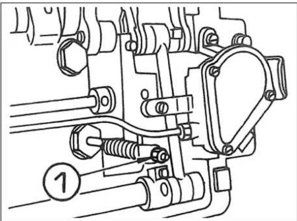
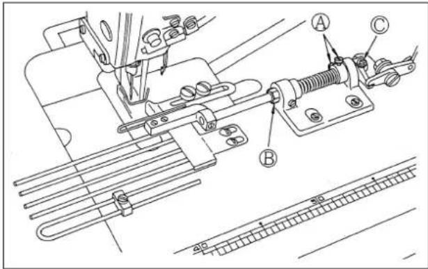
10. ADJUSTING THE REMAINING LENGTH OF TRIMMED THREAD (MH-481-4, MH-481-5, MH-484-4, MH-484-5)

WARNING :
To avoid possible personal injury due to abrupt start of the machine, turn off the power to the machine and check to be sure that the motor has totally stopped rotating in prior.
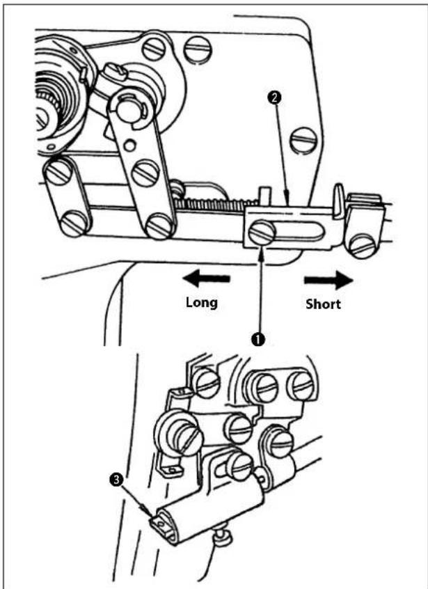
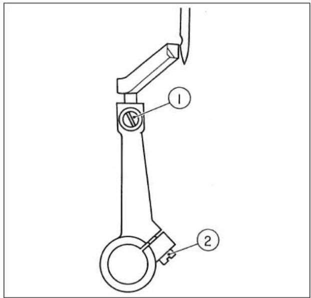
The length of the thread remaining on the needle after thread trimming signifi cantly affects the occurrence of stitch skipping at the beginning of sewing.
Loosen setscrew ① and move wire drawing link ② of the needle thread draw-out solenoid to the left to increase the thread take-up amount of draw-out pin ③. This increases the length of thread remaining at the bottom of the needle eyelet. On the contrary, moving the link to the right decreases it.
Reduce the length of thread remaining on the needle after thread trimming when using elastic thread such as Tetoron thread and nylon thread.
11. HOW TO INSTALL THE SILICON OIL LUBRICATING UNIT
natural_image
Technical line drawing of a mechanical clamp or bracket assembly with no visible text or symbolsMODEL MH-481 is provided with SILICON OIL LUBRICATING UNIT, which is available on an extra order, for sewing with synthetic or mixed synthetic thread. Separately place an order with us, if necessary.
As shown in the figure left, install the silicon oil lubrication unit into the frame thread eyelet.
12. ADJUSTING THE PRESSER FOOT
natural_image
Technical line drawing of a mechanical component with rotational arrow and base plate (no text or symbols)Adjusting the pressure of the presser foot
If the pressure adjusting screw is turned to right, the pressure becomes stronger and if it's turned to left, the pressure becomes weaker. The standard pressure is 5 kg.
natural_image
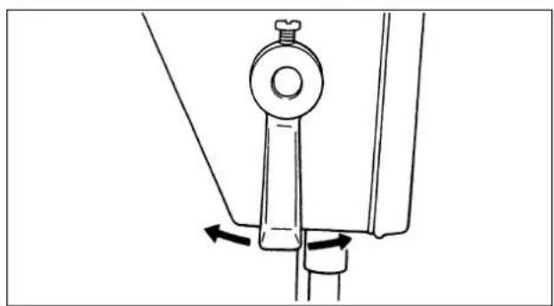
Mechanical assembly diagram showing a lever mechanism with directional arrows (no text or labels)Presser foot hand lifter
To stop the presser foot at the lifted position, rotate the presser foot hand lifter either to right or left.
To lower the presser foot, manipulate the knee lifter once and the presser foot will return to its original position.
natural_image
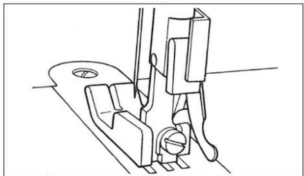
Technical line drawing of a mechanical assembly with no visible text or symbolsChain-off thread presser
(MH-481, MH-481-4, MH-481-5)
Irrespective of high speed or low speed sewing, a small chain-off thread presser is built-in in the MH-481 model so that the chain-off thread comes out easily. Conventional presser foot for general lock stitch can be used if no question is asked for chain-off thread.
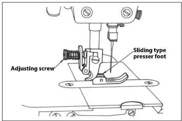
Sliding type presser foot
(MH-484, MH-484-4, MH-484-5)
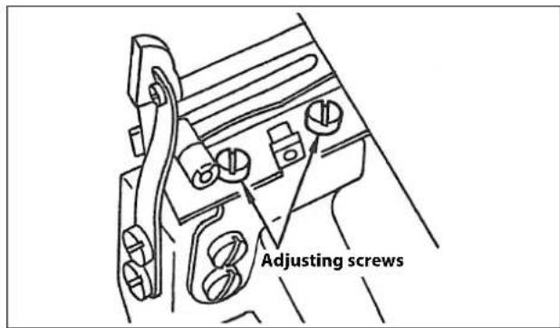
MH-484 has a sliding type presser foot. Adjust it as follows:
- Firmly tighten the presser spring regulator.
- Adjust for a proper sliding motion of the foot by tightening or loosening the adjusting screw on the presser foot; if the screw is too tight, the work will be slipped and if it is too loose, the work will not be fed or pucker.
13. ADJUSTING THE STITCH LENGTH

WARNING :
To avoid possible personal injury due to abrupt start of the machine, turn off the power to the machine and check to be sure that the motor has totally stopped rotating in prior.
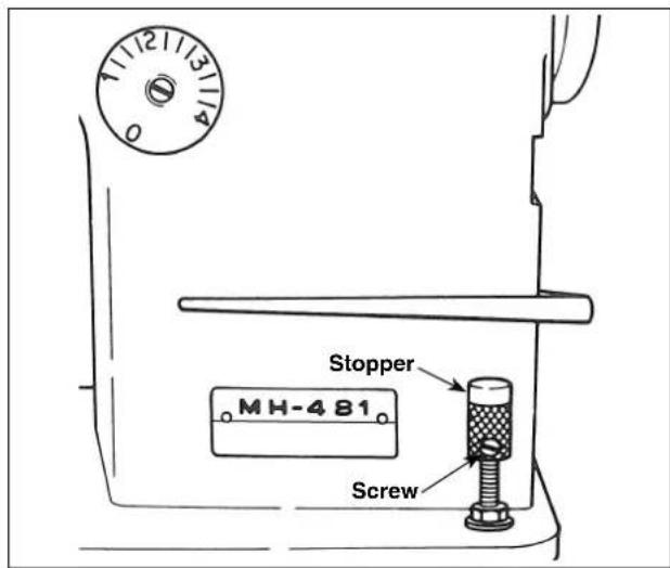
The stitch length of this model can be adjusted by rotating the feed adjusting dial on top of the feed lever.
The figures on the graduation scale is shown in millimeter (mm).
- Rotate the feed adjusting dial either to right or left and
- Match the wanted figure with the pin coming out from the frame.
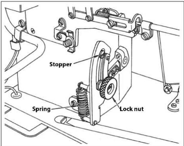
* The maximum stitch length is 4 mm (5/32"). - If the lever is pushed, it becomes reverse sewing with the standard pitch of 2 mm (5/64").
- If the position of the lever stopper is raised, the pitch of the reverse sewing becomes small.
- If the position of the lever stopper is raised up further (loosen the nut and pull the stopper up) and the lever is pushed, it is possible to sew with normal sewing with small stitch length.
Take advantage of this feature for bar-tacking at the start of sewing or end of sewing.
(Caution) This function is not applicable to thread trimming in the case of reverse-feed stitching.
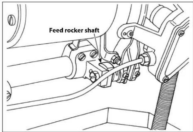
MH-484, MH-484-4, MH-484-5/S060
When feed rocker shaft shows a greater motion like MH-484/S060, the stitch length on the dial indicates one half of the actual stitch length.
14. DIFFERENTIAL FEED ADJUSTMENT (MH-484, MH-484-4, MH-484-5)

WARNING :
To avoid possible personal injury due to abrupt start of the machine, turn off the power to the machine and check to be sure that the motor has totally stopped rotating in prior.
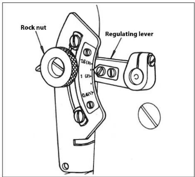
Loosen the lock nut of the regulating lever and adjust the lever angle; pull up the lever for gather stitch and push it down for stretch sewing.
The figures on the differential feed dial indicate the ratio of the auxiliary feed to the main feed.
(For example, "0.5" represents 0.9 mm of auxiliary feed when the main feed is 1.8 mm)
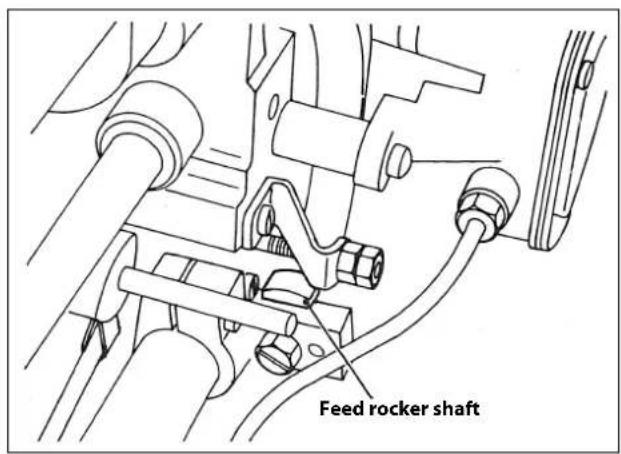
When a greater effect of gather stitch is required, provide the feed rocker shaft with a larger motion by increasing the radius of the arm.
For this purpose, use the figures in parenthesis on the dial.
(For example, "2.5" represents 4.5 mm of the auxiliary feed when the main feed is 1.8 mm) However, take care that the feed ratio will vary according to the difference in the tooth pitch between the main and differential feed dogs. Therefore, the indication on the dial must be used as just a reference value.
15. HEIGHT AND ANGLE OF THE PRESSER FOOT

WARNING :
To avoid possible personal injury due to abrupt start of the machine, turn off the power to the machine and check to be sure that the motor has totally stopped rotating in prior.
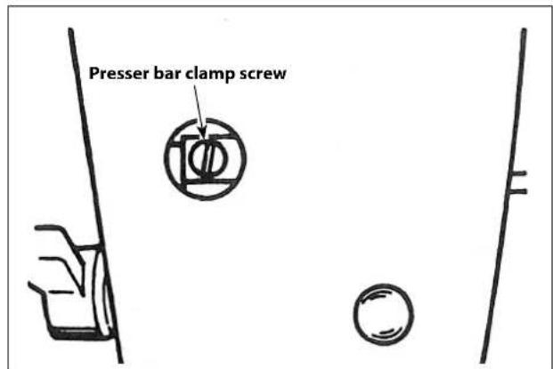
When the height or the direction of the presser bar is to be changed due to the exchange of presser foot:
- Remove the rubber plug of the face plate.
- From this hole, adjust by loosening the presser bar clamping screw.
- After the adjustment, securely tighten the set screw.
16. ATTACHING THE FEED DOG

WARNING :
To avoid possible personal injury due to abrupt start of the machine, turn off the power to the machine and check to be sure that the motor has totally stopped rotating in prior.
[MH-481, MH-481-4, MH-481-5]
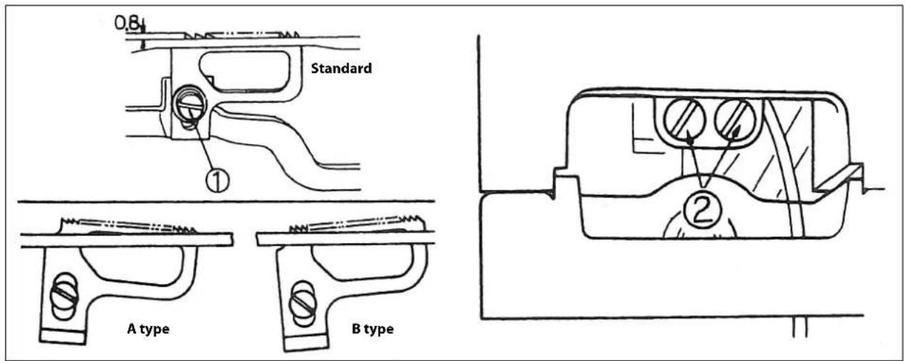
If the screw ② of figure is loosened, the slant of the feed dog can be adjusted either to A type or B type. The maximum protruding amount of the feed dog is 0.8 mm(1/32"). Adjust to this amount by screw ①.
[MH-484, MH-484-4, MH-484-5]
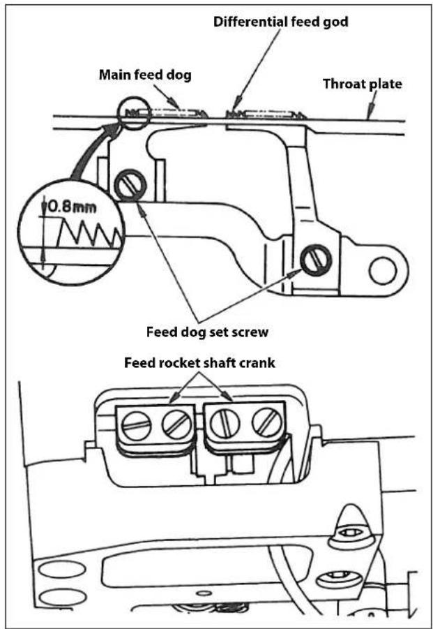
The standard height of the main feed dog is 0.8 mm (1/32") above the throat plate surface. At the highest point, the main feed dog must be in a front-up (down slope) posture and the differential feed dog must be in horizontal position as illustrated.
Also adjust the differential feed dog to sink in the throat plate simultaneously with the main feed dog.
These adjustment are made by means of the feed dog setscrews and the feed rocker shaft crank.
17. ADJUSTING THE FEED TIMING

WARNING:
To avoid possible personal injury due to abrupt start of the machine, turn off the power to the machine and check to be sure that the motor has totally stopped rotating in prior.
[MH-481, MH-481-4, MH-481-5]
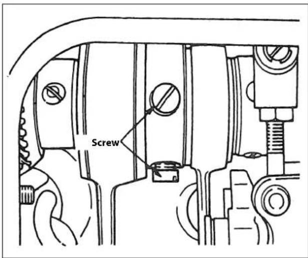
When the needle point has dropped to 3mm (1/8") bottom the surface of the throat plate, adjust the position of the feed dog by the screw of figure so that the feed dog sinks just below the lower surface of the throat plate.
[MH-484, MH-484-4, MH-484-5]
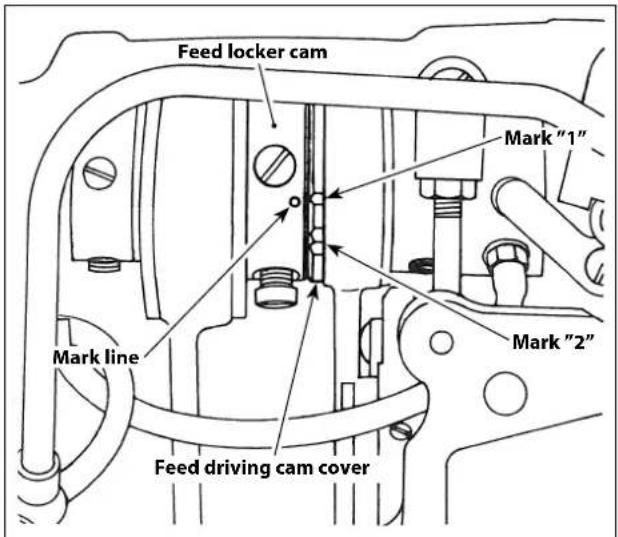
Timing of the feed rocker cam (trajectory of the feed dog) must be changed for stretch or gather sewing.
Remove the side plate located on the rear of the machine arm and loosen the feed rocker cam setscrew.
Adjust the mark line on the feed rocker cam to the marks "1" shown by the feed driving cam cover for stretch sewing and "2" for gather sewing.
After adjusting the feed rocker cam, tighten its setscrew. All machines have been set for stretch sewing (Mark "1") before shipment, excepting MH-484 and MH-484-4-S060 & S061 which have been set for gather sewing (Mark "2").
After changing the timing of feed rocker shaft cam, readjust the height of the feed dogs accordingly.
18. COUNTERFORCE OF THE FEED LEVER

WARNING :
To avoid possible personal injury due to abrupt start of the machine, turn off the power to the machine and check to be sure that the motor has totally stopped rotating in prior.
natural_image
Technical line drawing of a mechanical assembly with no visible text or symbolsThe reversing spring of the feed lever is strengthened somewhat so that at high speed sewing, no matter what kind of stitches are to be formed, the lever returns positively to the original position.
When you wants to lessen the pressing force for sewing with the smaller stitches or for operating the machine at a lower speed, you can adjust the counterforce by changing the position of spring shown in the illustration.
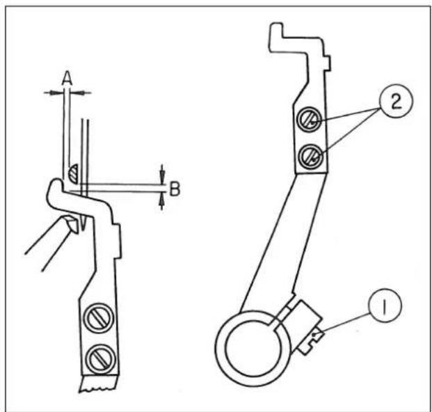
19. NEEDLE-TO-LOOPERRELATION

WARNING :
To avoid possible personal injury due to abrupt start of the machine, turn off the power to the machine and check to be sure that the motor has totally stopped rotating in prior.
natural_image
Simple line drawing of a vehicle with a circular head, a vertical pole, and a target symbol (no text or labels)Adjust the needle and the looper as described below:
- Turn the handwheel to bring the needle bar to the lowest position of its stroke. Loosen needle bar connection setscrew ①.
(Determining the needle bar height)
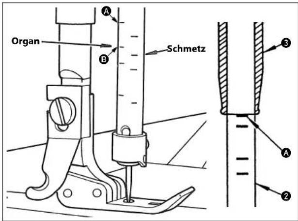
- Align first (uppermost) marker lin A on needle bar ② with the bottom end face of needle bar lower bushing ③. Tighten needle bar connection setscrew ①.
In the case ORGAN needle (TV×7) is used, use the marker lines on the left side of the needle bar. In the case Schmetz needle (such as UY-128GAS), use the marker lines on the right side of the needle bar.
(Determining the looper position)
-
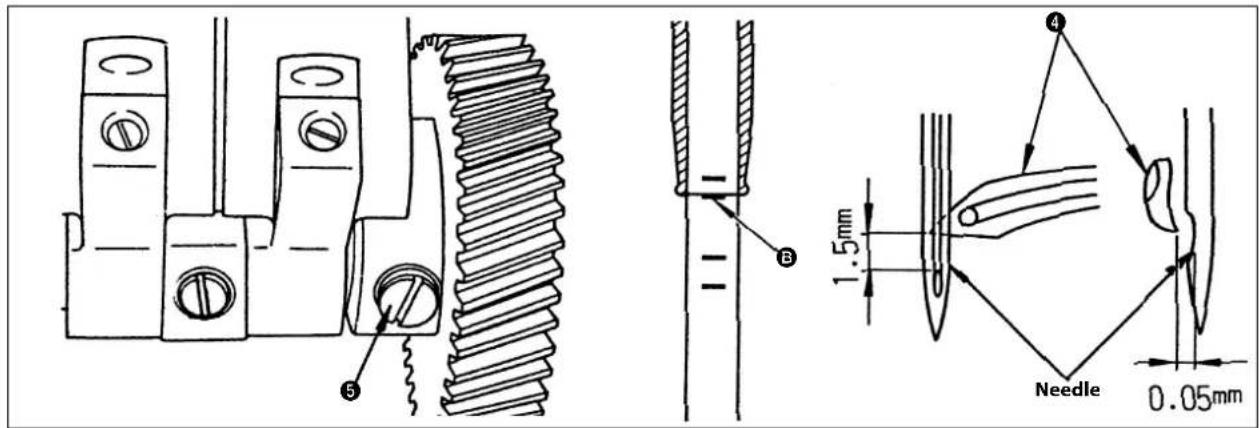
Loosen gear setscrew ⑤ to adjust so that looper ④ reaches its back end when the needle bar is at the lower point of its stroke.
-
Carry out adjustment so that the blade point of looper ④ aligns with the center of the needle, so that the former is spaced 1.5 mm from the upper end of needle eyelet and so that a clearance of 0.05 mm is provided between the looper and the needle when second marker line B on needle bar ② is aligned with the bottom end of needle bar lower bushing ③.
-
Loosen looper setscrew ⑥ and looper clamping screw ⑦ and carry out the adjustment.
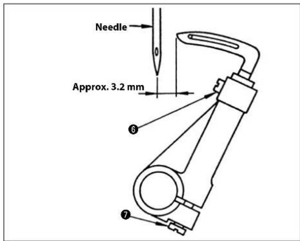
-
Check to be sure that a distance of approximately 3.2 mm is provided between the center of the needle and the blade point of the looper when the looper reaches its back end.
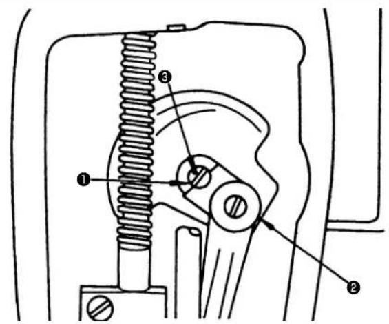
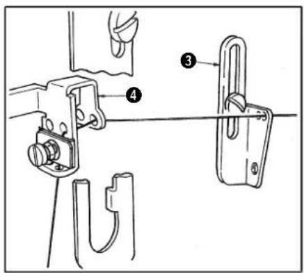
To avoid possible personal injury due to abrupt start of the machine, turn off the power to the machine and check to be sure that the motor has totally stopped rotating in prior.
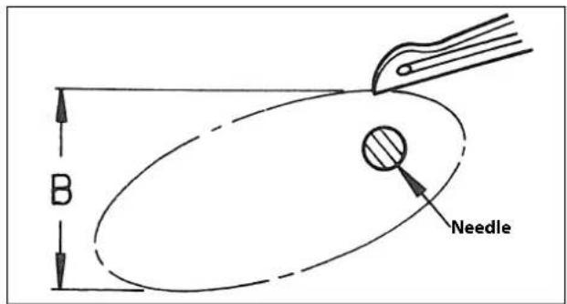
Within the oval movement of the looper, the dimension of B in the figure can be adjusted in the following order.
- Remove the rubber cap.
- Rotate the hand wheel with the hand.
- The heads of the plated adjusting screw ①, flat at top screw, clamp screw will appear in that order, so at first, loosen the 2 screws, flat top and clamp screw.
- If the punched mark ② of the adjusting screw ① is brought to right side, the dimension of B becomes bigger.
- Adjustment is made depending on the size number of the needle but normally it is adjusted to #11 needle.
- The adjustment should be made so that the looper goes as near the needle side as possible and returns. Then, after setting the position by tightening the fl at top screw, securely tighten the clamp screw.
21. THREADSPREADER

WARNING:
To avoid possible personal injury due to abrupt start of the machine, turn off the power to the machine and check to be sure that the motor has totally stopped rotating in prior.
Thread spreader is necessary in case of reverse sewing and at the same time it is very important to obtain stable stitches without skip-stitching in case of normal feed sewing.
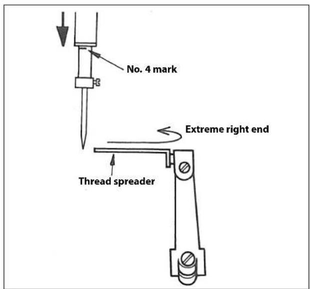
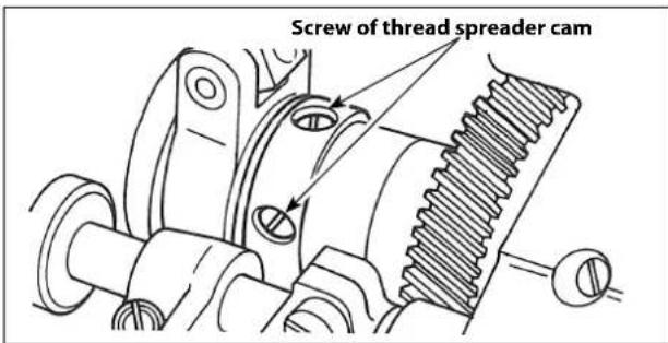
The timing of thread spreader against the needle
As shown in the figure, when the No.4 mark of the needle bar appears from the bottom of the needle bar lower bushing, set the thread spreader with the thread spreader cam set screw, as shown in the figure, so that the thread spreader comes to extreme right end.
MH-481, MH-484
Position of the thread spreader latch
When the pointed end of the descending needle arrives the level of upper surface of the looper, adjust the thread spreader to the position shown by the figure.
① The right and left direction should be such that the inside surface of the thread spreader should match with the center of the needle.
② Adjust so that the front and back dimension A should be 2 mm (5/64") with the screw 1.
③ The height should be adjusted so that the clearance between the bottom surface of the thread spreader and the upper surface of the looper to be 0.2 mm (1/100") with the screw ②.
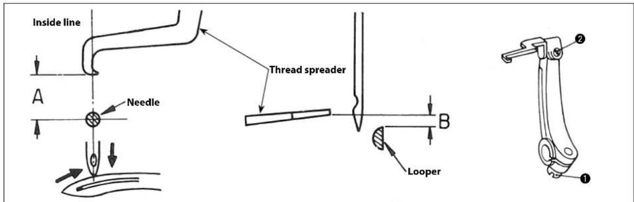
MH-481-4, MH-481-5, MH-484-4, MH-484-5
Lower the needle. Position the thread spreader as illustrated above.
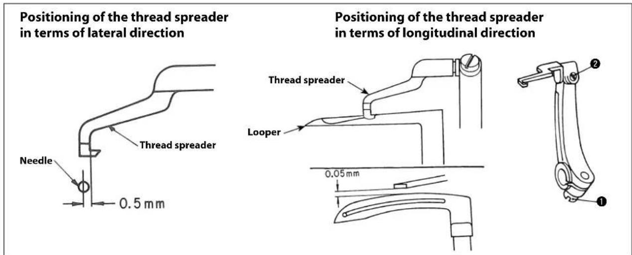
① For the lateral direction, adjust the position of the thread spreader so that a clearance of 0.5 mm is provided between the center line of the needle and the inner side line when the third marker line on the needle bar appears from the bottom end of the needle bar lower bushing.
② For the longitudinal direction, adjust the position of the thread spreader using screw ① so that the thread spreader aligns with the read surface of the looper.
③ Adjust the height of the thread spreader using screw ② so that a clearance of 0.05 mm is provided between the bottom face of the thread spreader and the top face of the looper when the needle bar is in its upper dead point.
MH-481, MH-484
MH-481-4, MH-481-5, MH-484-4, MH-484-5
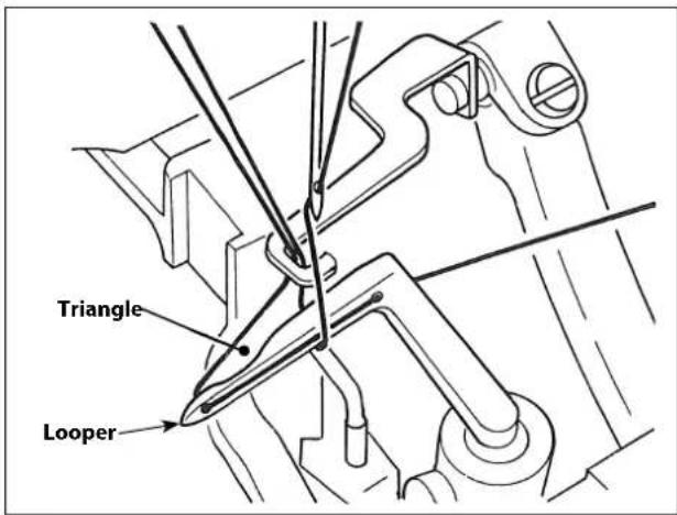
Method of thread spreader
① When the thread spreader latch returns, the tip of the thread spreader latch is positively grasping the looper thread and one side of the needle thread loop until the needle point enters the triangle of the thread.
② After the needle point has entered the triangle, the looper should release the thread.
Above are the thread spreader adjustments for both normal and reverse stitches to form correct stitches.
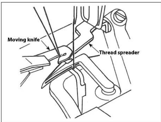
Function of the thread spreader (especially when the threads are trimmed).
The thread spreader firmly holds the looper thread and the needle thread at 2 places of a loop before the needle goes up to it's upper dead position to stop. Then, the tip of the moving knife comes to hook these 2 threads and trims them off.
22. MATCHING THE MOTION OF THE NEEDLE GUARDS WITH THE LOOP GUIDE

WARNING :
To avoid possible personal injury due to abrupt start of the machine, turn off the power to the machine and check to be sure that the motor has totally stopped rotating in prior.
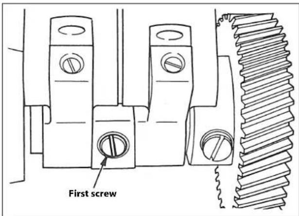
The timing of the needle guard
The timing of the needle guard is determined by matching the first screw of the figure with the flat part of the shaft.

Position of the needle guard
When the looper scoops up the needle thread, adjust so that the needle point lightly touches the needle guard. Set the height as high as possible to about cover the needle thread loop. Loosen set screws ① and ② for this adjustment.
Position of the looper guide
The looper guide should be installed as near the looper as possible so that it will not touch the looper. Adjust it so that the dimension of A will be about 0.2—0.5 mm (1/100"—1/64"), and of B to be about 0.5—1.0 mm (1/64"—3/64").
Dimension of A should be adjusted by loosening screw ① and of B loosen screw ②.
23. POSITIONING THE LOOPER THREAD TAKE-UP

WARNING :
To avoid possible personal injury due to abrupt start of the machine, turn off the power to the machine and check to be sure that the motor has totally stopped rotating in prior.
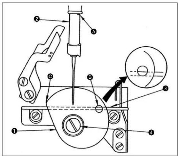
Loosen setscrew ④. Adjust the position of looper thread cam ① so that wire ③ is visible through guide hole B when third marker line A (third from the top) of the needle bar ② aligns with the bottom end face of the needle bar lower bushing.
After the adjustment, verify the following.
- When the looper thread moves off tip © of the looper thread cam, the needle tip fully enters the looper thread triangle.
- In the case puckering is particularly concerned, the bottom face of the wire aligns with the bottom end of guide hole Ⓑ slightly earlier than the normal timing.
24. POSITION OF THE THREAD TAKE-UP LEVER

WARNING :
To avoid possible personal injury due to abrupt start of the machine, turn off the power to the machine and check to be sure that the motor has totally stopped rotating in prior.
natural_image
Technical line drawing of a mechanical assembly with no visible text or symbolsA larger loop is formed by the needle thread and, at the same time, a formed loop is more tightened by adjusting the motion of the thread take-up lever in such a manner as to haul the needle thread, upwards, as shown in the illustration, when the needle bar has reached it's bottom dead point.
When a thin thread is used, you must bring the thread take-up lever down to the lowest position.
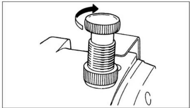
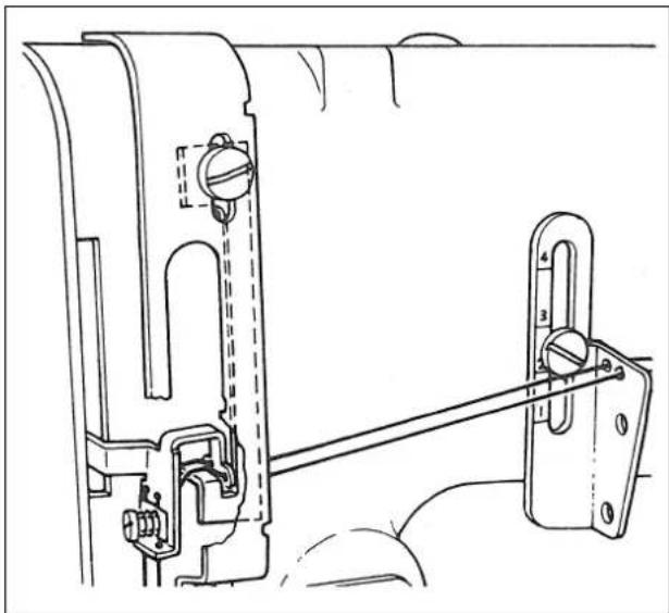
25. POSITION OF THE FRAME THREAD EYELET
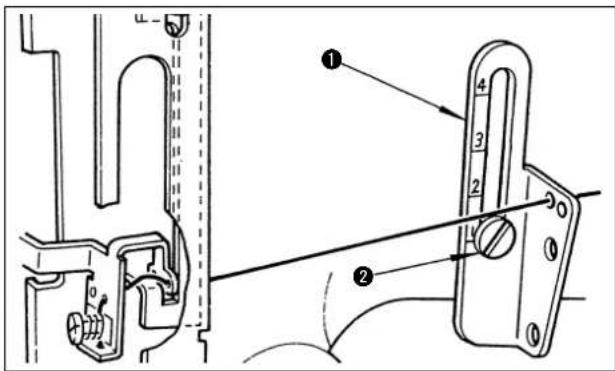
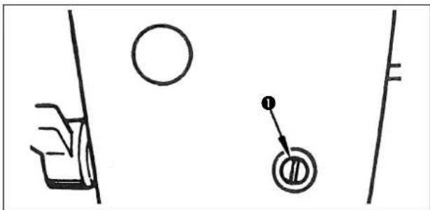
The thread tension changes by moving intermediate thread guide ① up and down.
The thread tension is increased by moving the intermediate thread guide upward, or decreased by moving it downward. In general, adjust the position of setscrew ② referring to the table below.
| Thread used | Scale on the intermediate thread guide | |
| Cotton thread | #80 to #50 | 2 to 3 |
| #30 to #20 | 3 to 4 | |
| Synthetic thread | #80 to #50 | 1 to 2 |
| #30 to #20 | 2 to 3 | |
26. THREAD TRIMMING (MH-481-4, MH-481-5, MH-484-4, MH-484-5)

WARNING :
To avoid possible personal injury due to abrupt start of the machine, turn off the power to the machine and check to be sure that the motor has totally stopped rotating in prior.
1. Moving knife mounting plate assembly
The preliminary test for thread trimming and thread clamping can be done independently on the moving knife mounting plate assembly.
(After the following adjustments have been completed, hook the threads manually with the recessed part of the moving knife, pull the moving knife into the counter knife to clamp the threads and the thread will be trimmed off.)
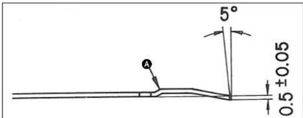
Dimensions of the counter knife
When sharpening the counter knife, correct it with the part A so as to finish it in the size of 0.5 ± 0.05 mm.
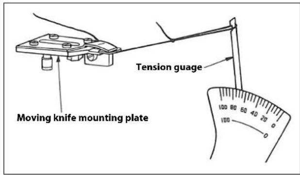
Adjustment of the clamping pressure
The looper thread clamping pressure applied by the thread clamping spring is always constant regardless of the type of sewing threads, which you need not to change. If the looper thread is not clamped correctly, you must replace the moving knife assembly. When a cotton thread No.60 is clamped and is pulled away as shown in the illustration, the correct tension is between 70 and 100g. The top end of the spring and the bottom surface of the moving knife must evenly engage with each other. Do not change the thread clamping pressure since it has been properly factory-adjusted at the time of delivery.
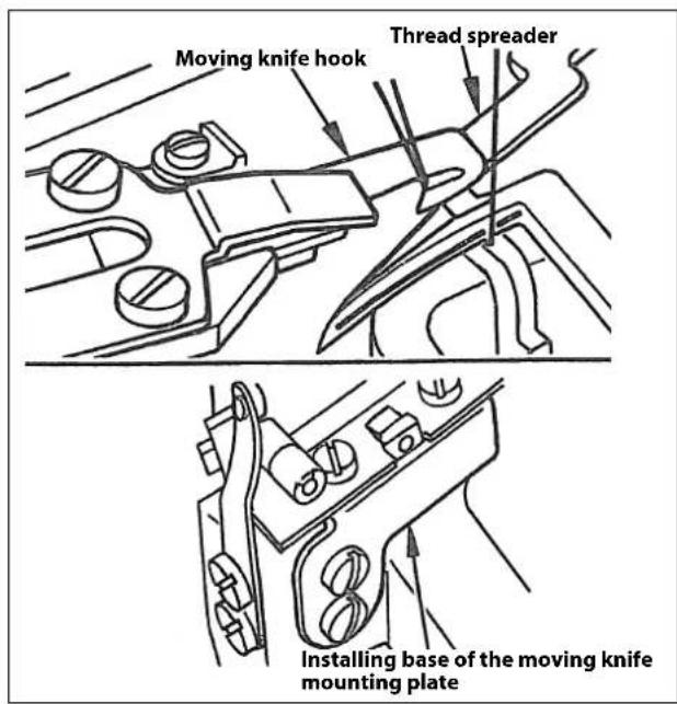
2. Positioning the moving knife
The position of the moving knife is determined by those of the moving knife base, moving knife base mounting plate and the stopper.
Lateral position of the moving knife base
Adjust it within a range provided by the oval screw holes.
If you move it to the right, the length of thread remaining on the needle is increased.
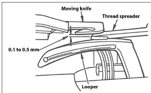
Longitudinal position of the moving knife base
Provide a clearance of 0.1 mm to 0.5 mm between the moving knife and the thread spreader so that the knife does not hit the spreader when the former approached to the latter.
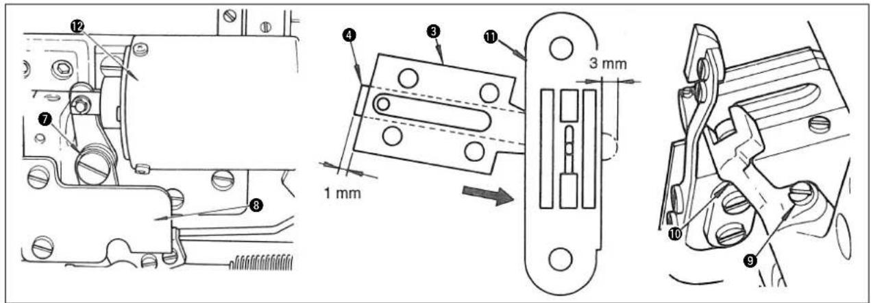
Stroke of the moving knife
Loosening screw ⑨, perform adjustment by knife driving fork ⑩ so that the rear end of moving knife ④ projects 1 mm from counter knife ③ with thread trimmer lever ⑦ in contact with stopper ⑧.
Then adjust the position of solenoid ⑫ to make moving knife ④ stop at 3 mm from throat plate ⑪ at when it is moved to its farthest point.
Longitudinal position of the moving knife
The moving knife must go back accompanying 2 threads which had been held by the thread spreader without fail. If not, adjust the longitudinal position of the moving knife by moving the mounting plate so that the knife hooks 2 of the thread being held by the spreader regardless of the stroke.
27. ADJUSTING THE WIPER (MH-481-4, MH-481-5, MH-484-4, MH-484-5)

WARNING :
To avoid possible personal injury due to abrupt start of the machine, turn off the power to the machine and check to be sure that the motor has totally stopped rotating in prior.
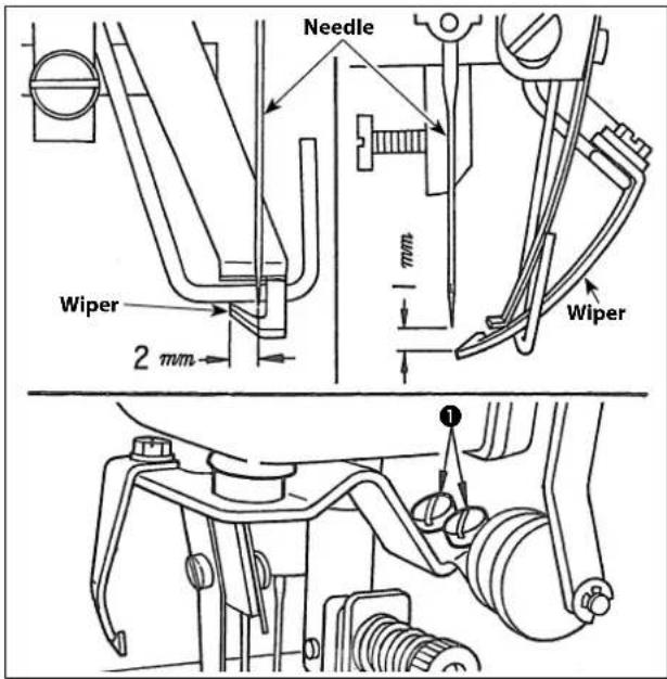
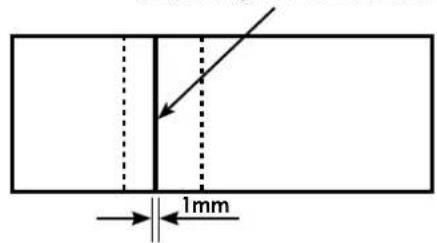
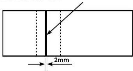
Position of the wiper against the needle
The vertical clearance between the wiper and the needle point must be 1 mm and the horizontal clearance with the needle center must be 2 mm. You can adjust it by loosening the screw on the wiper driving arm set screw ①.
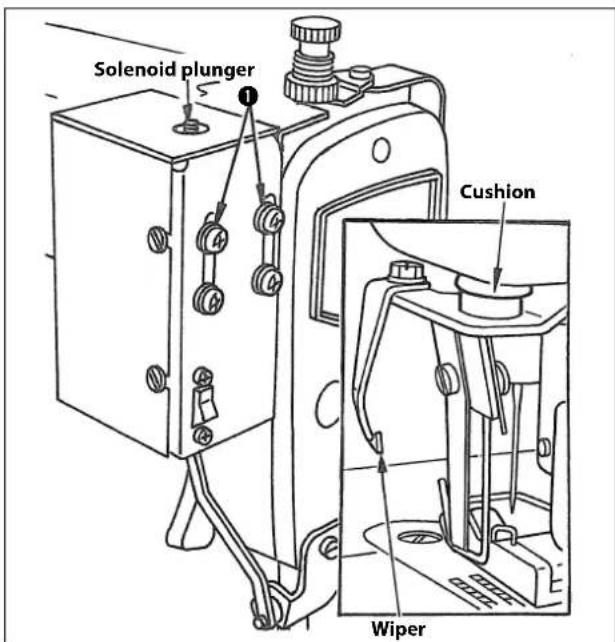
The most frontward position of the wiper
The most frontward position of the wiper is determined by the position of the wiper driving solenoid. Adjust the position of the solenoid by means of the screw ① so that the top end of the wiper reaches the left end of the presser foot when the solenoid plunger has gone up to it's highest position.
* After a proper position has been obtained, check that the wiper does not contact with the needle and also that the cushion attached to the wiper driving arm rests on the bottom surface of the arm when the wiper has been brought back. If the cushion does not rest on the arm surface, you must adjust the position of the solenoid, because the solenoid has been installed at a higher position or the stroke of the solenoid is shorter than the standard of 8.5 mm.
28. ADJUSTING THE NEEDLE THREAD CLAMPING ARM (MH-481-4, MH-481-5, MH-484-4, MH-484-5)

WARNING :
To avoid possible personal injury due to abrupt start of the machine, turn off the power to the machine and check to be sure that the motor has totally stopped rotating in prior.
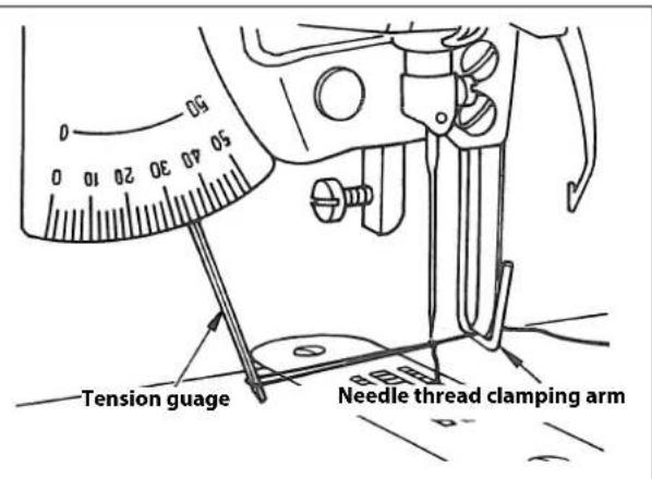
The function of the needle thread clamping arm is to clamp the needle thread which was handled by the wiper in order to prepare for the following sewing works. Adjust the tension of the spring so that the clamping pressure is in a range of 30 to 40 g when the cotton needle thread No. 60 is being pulled out. This pressure is common to all kinds of sewing threads. Therefore, you do not need to change the aforementioned pressure every time after a thread is replaced.
* Adjust it with care not to apply uneven pressure to the spring.
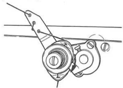
29. ADJUSTING THE DRAW-OUT AMOUNT OF THE LOOPER THREAD (MH-481-4, MH-481-5, MH-484-4, MH-484-5)

WARNING :
To avoid possible personal injury due to abrupt start of the machine, turn off the power to the machine and check to be sure that the motor has totally stopped rotating in prior.
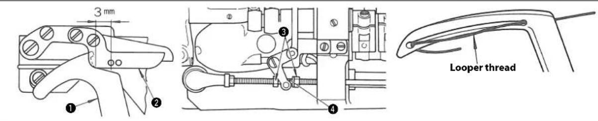
The standard amount of looper thread is drawn out when looper thread draw-out lever ① is spaced 3 mm from the thread path hole in cam thread guide ② immediately before the thread trimmer is actuated. Loosen nut ③ and make adjustment by moving cam thread tension release slide block ④ to the right or left.
For certain types of needle, the looper thread may slip off the looper. In such a case, make adjustment so that a longer thread is drawn out.
30. GATHER SEWING ATTACHMENT (MH-484, MH-484-4, MH-484-5)

WARNING :
To avoid possible personal injury due to abrupt start of the machine, turn off the power to the machine and check to be sure that the motor has totally stopped rotating in prior.
Attachments S060 and S061 are available for the model MH-484.
S060 (Gather sewing attachment)
With S060, you can gather only the bottom cloth.
S061 (Intermittent gather sewing attachment)
With S061 you can intermittently sew gathers as you wish by operating the pedal lever.
natural_image
Technical line drawing of a mechanical assembly with gears, springs, and housing (no text or symbols)Refer to the separate Instruction Book prepared for the S060, S061 for the details of adjustment.
31. MOTOR PULLEY AND SEWING SPEED (MH-481, MH-484)
1) Use the 3-phase 400 W AC clutch motor.
2) Use an M type V belt.
3) The following table shows the relationship among the motor pulley and the sewing speed.
| Model Sewing speed | Effective diameter of handwheel | Number of poles | Frequency | Rotational speed of motor | Effective diameter of motor pulley | |
| MH-481 MH-484 | 5,500 sti/min | 67.4 mm 2 | 50 Hz 2,8 | 65 rpm | 130 | |
| 60 Hz 3,4 | 30 rpm | 110 | ||||
| 5,000 sti/min | 50 Hz 2,8 | 65 rpm | 115 | |||
| 60 Hz 3,4 | 30 rpm | 100 | ||||
| 4,500 sti/min | 50 Hz 2,8 | 65 rpm | 105 | |||
| 60 Hz 3,4 | 30 rpm | 90 | ||||
(Caution) The effective diameter of the motor pulley is obtained by subtracting 5 mm from the outside diameter.
32. TROUBLES IN SEWING AND CORRECTIVE MEASURES
| Troubles Causes Corrective measures | ||
| 1. Thread breakage | 1 Thread quality is poor.2 Thread is too thick for the needle.3 Thread breakage due to the heated needle.4 Thread tension is too high.5 The thread path of needle, looper, throat plate, needle guard, looper guide and all other thread paths are bruised.6 Excessive thread is remained and hooked again. | ○ Use another thread of better quality.○ Change such thread or needle.○ This occurs on synthetic fi ber thread.Apply silicon oil lubricant (refer to “11. HOW TO INSTALL THE SILICON OIL LUBRICATION UNIT”) or reduce the sewing speed.○ Lessen the thread tension.Refer to “9. THREAD TENSION”.○ Make them smooth by means of oilstone or buffi ng.○ Activate the thread take-up tension lever.Refer to “24. POSITION OF THE THREAD TAKE-UP LEVER”. |
| 2. Skip-stitch | 1 Two consecutive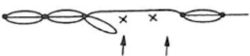 Stitches are skipped on the needle thread.(This trouble is caused when the looper failed to hook the needle thread.) Stitches are skipped on the needle thread.(This trouble is caused when the looper failed to hook the needle thread.)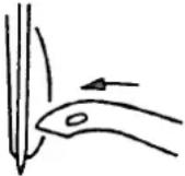 2 An independent seam is skipped on the looper thread. 2 An independent seam is skipped on the looper thread.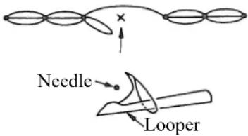 This trouble is caused when the needle failed to come down through a triangular loop formed by the looper thread. This trouble is caused when the needle failed to come down through a triangular loop formed by the looper thread. | ○ Verify the looper motion.Refer to “19. NEEDLE-TO-LOOPER RELATION”.○ Verify the clearance between the looper and the needle.Refer to “19. NEEDLE-TO-LOOPER RELATION”.○ Check the timing of the looper and the needle.Refer to “19. NEEDLE-TO-LOOPER RELATION”.○ Try to increase the tension of the thread take-up lever depending upon the type of thread.Refer to “24. POSITION OF THE THREAD TAKE-UP LEVER”.○ Verify the needle is attached correctly.Refer to “6. ATTACHING THE NEEDLE”.○ Check the position and the timing of the needle guard.Refer to “22. MATCHING THE MOTION OF THE NEEDLE GUARDS WITH THE LOOP GUIDE”.○ Verify the thread is correctly passed through.Refer to “7. THREADING THE MACHINE HEAD” and “8. THREADING THE LOOPERS”.○ Verify the looper motion.Verify the clearance between the looper and the needle.Refer to “19. NEEDLE-TO-LOOPER RELATION”.○ Check the timing of the looper thread take-up.Refer to “23. POSITIONING THE LOOPER THREAD TAKE-UP”.○ Adjust the position of the thread spreader hook.Refer to “21. THREAD SPREADER”.○ Increase the looper thread tension slightly.Refer to “9. THREAD TENSION”.○ Verify the thread is correctly passed through.Refer to “7. THREADING THE MACHINE HEAD” and “8. THREADING THE LOOPERS”. |
3 Seam is skipped on the needle thread due to insufficient interlooping.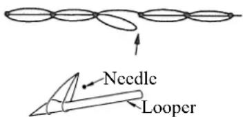 This trouble is caused when the needle thread is inclined extremely to the left.If it is caused in the use of a chemical fi ber thread.If it is caused in the use of a synthetic fi ber thread. This trouble is caused when the needle thread is inclined extremely to the left.If it is caused in the use of a chemical fi ber thread.If it is caused in the use of a synthetic fi ber thread. | ○ Verify the looper motion.Verify the clearance between the looper and the needle.Refer to “19. NEEDLE-TO-LOOPER RELATION”.○ Reduce the sewing speed.○ Apply silicon oil lubricant.Refer to “11. HOW TO INSTALL THE SILICON OIL LUBRICATING UNIT”.○ Use a needle for chemical fi ber threads.○ Make the scooping amount of looper greater.Refer to “19. NEEDLE-TO-LOOPER RELATION”.○ Reduce the sewing speed.○ Apply silicon oil lubricant.Refer to “11. HOW TO INSTALL THE SILICON OIL LUBRICATING UNIT”. | |
| 3. Inadequate tightness of stitches | 1 Needle thread tension is too low.2 Looper thread tension is too high.3 Looper thread take-up does not supply a sufficient length of thread.4 Thread is too thick for the needle size. | ○ Tighten the needle thread tension nut.Refer to “9. THREAD TENSION”.○ Loosen the looper thread tension nut.Refer to “9. THREAD TENSION”.○ Change the threading order in the looper thread guide.Refer to “23. POSITIONING THE LOOPER THREAD TAKE-UP”.○ Try to use a different needle.Refer to “6. ATTACHING THE NEEDLE”. |
| Troubles Causes | Corrective measures | |
| 5 Set position of the frame thread eyelet is not suitable.6 Position of the thread take-up lever is not suitable.7 Throat plate does not fi t. | ○ Try to lower the position.Refer to “25. POSITION OF THE FRAME THREAD EYELET”.○ Try to push it up.Refer to “24. POSITION OF THE THREAD TAKE-UP LEVER”.○ Replace it with other throat plate which has larger needle hole. | |
| 4. Needle breakage | 1 Needle is bent.2 The timing of the needle motion with that of needle is not correct.3 Position of the presser foot is wrong.4 Motion of the needle guard is not adequate.5 The tension of needle thread is too high.6 Thickness of the needle is not suitable. | ○ Replace it with a straight needle.Refer to “6. ATTACHING THE NEEDLE”.○ Adjust the timing.Refer to “17. ADJUSTING THE FEED TIM-ING”.○ See if the hole of presser foot, hole of throat plate and loop guide plate are placed in the center of needle.○ Check the position and timing of the motion of the needle guard.Refer to “22. MATCHING THE MOTION OF THE NEEDLE GUARDS WITH THE LOOP GUIDE”.○ Loosen the tension.Refer to “9. THREAD TENSION”.○ Replace it with a suitable needle in accordance with the quality and weight of the sewing material.Refer to “6. ATTACHING THE NEEDLE”. |
| 5. Puckering | 1 Thread tension is too high.2 Timing of the looper thread take-up is wrong.3 Thread paths are not smooth.4 Pressing force of the presser foot is too much5 Needle6 Throat plate. | ○ Reduce the thread tension, especially the looper thread.Refer to “9. THREAD TENSION”.○ Set the timing to a little earlier.Refer to “23. POSITIONING THE LOOPER THREAD TAKE-UP”.○ Polish the thread path with lapping agent on thick thread #8.○ Tighten the adjusting screw.Refer to “12. ADJUSTING THE PRESSER FOOT”.○ Use a fi ner needle.○ Use a throat plate designed for fi ne materials.○ Ratio of differential feed; Apply 1:0.7 ratio for gathering. |
| 6. Puckering | 1 Presser foot2 Pressure of presser foot | ○ Use a sliding type presser foot.Refer to “12. ADJUSTING THE PRESSER FOOT”.○ Reduce the pressure.Refer to “12. ADJUSTING THE PRESSER FOOT”. |
DEUTSCH
Hazardous voltage will cause injury.
Turn off main switch and unplug power cord and wait at least 5 minutes before opening this cover.

GEFAHR

Minimaler Ölfluss

Maximaler Öfluss
flowchart
graph TD
    A["A"] --> B["B"]
    B --> C["C"]
    C --> Transport["Transportrichtung"]
    Transport --> A
    Transport --> B
    Transport --> C

MH-481-4, MH-481-5, MH-484-4, MH-484-5

[MH-481-4, MH-481-5, MH-484-4, MH-484-5]
natural_image
Mechanical assembly diagram showing a gear mechanism with no visible text or symbolsnatural_image
Technical line drawing of a mechanical linkage or clamping mechanism (no text or symbols)[MH-481-4, MH-481-5, MH-484-4, MH-484-5]

natural_image
Technical line drawing of a mechanical assembly with no visible text or symbolsnatural_image
Technical line drawing of a mechanical clamp or bracket assembly with no visible text or symbolsnatural_image
Technical line drawing of a mechanical component with rotational arrow and base plate (no text or symbols)natural_image
Mechanical assembly diagram showing a lever mechanism with directional arrows (no text or labels)Nähfuß-Handheber
natural_image
Technical line drawing of a mechanical assembly with no visible text or symbolsKettelfadendrücker
(MH-481, MH-481-4, MH-481-5)
natural_image
Technical line drawing of a mechanical assembly with no visible text or symbolsnatural_image
Simple line drawing of a vehicle with a circular head, a vertical pole, and a target symbol (no text or labels)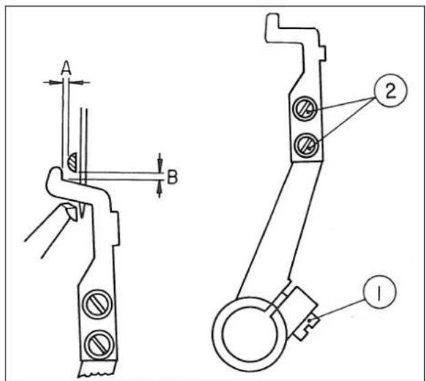
natural_image
Technical line drawing of a mechanical assembly with no visible text or symbolsnatural_image
Technical line drawing of a mechanical assembly with hoses, gears, and a motor (no text or symbols)Hazardous voltage will cause injury.
Turn off main switch and unplug power cord and wait at least 5 minutes before opening this cover.
PRÉCAUTIONS DE SÉCURITÉ
CARACTERISTIQUES....1
- INSTALLATION....2
- REGLAGE DE LA TENSION DE COURROIE....3
- POSE DU PORTE-BOBINES .... 3
- LUBRIFICATION......4
- POSE DU COUVRE-COURROIE ....6
- POSE DE L'AIGUILLE....6
- ENFILAGE DE LA TETE DE LA MACHINE ....7
- ENFILAGE DES BOUCLEURS....8
-
TENSION DES FILS 9
-
RÉGLAGE DE LA LONGUEUR RESTANTE DU FIL COUPÉ (MH-481-4, MH-481-5, MH-484-4, MH-484-5)....9
-
COMMENT INSTALLER LE DISPOSITIF DE LUBRIFICATION À HUILE SILICONE.... 10
-
RÉGLAGE DU PIED PRESSEUR....10
-
REGLAGE DE LA LONGUEUR DES POINTS....11
-
AJUSTEMENT DE L'ENTRAÎNEMENT DIFFÉRENTIEL (MH-484, MH-484-4, MH-484-5) .....12
-
HAUTEUR ET ANGLE DU PIED PRESSEUR....12
-
FIXATION DE LA GRIFFE D'ENTRAÎNEMENT .... 13
-
CALAGE DE L'ENTRAINEMENT .... 14
-
CONTRE-FORCE DU LEVIER D'ENTRAÎNEMENT....15
-
RELATION ENTRE L'AIGUILLE ET LE BOUCLEUR....15
-
RÉGLAGE DU MOUVEMENT D'ÉVITEMENT DU BOUCLEUR 17
-
ETENDEUR DE FIL....17
-
CORRESPONDANCE ENTRE LE MOUVEMENT DES GARDE-AIGUILLES ET DU GUIDE DU BOUCLEUR....19
-
POSITIONNEMENT DU RELEVEUR DE FIL DU BOUCLEUR 20
-
POSITION DU LEVIER RELEVEUR DE FILS....21
-
POSITION DE L'ŒILLET POUR FIL DU CADRE....21
-
COUPE DU FIL (MH-481-4, MH-481-5, MH-484-4, MH-484-5)....21
-
RÉGLAGE DU TIRE-FIL (MH-481-4, MH-481-5, MH-484-4, MH-484-5)....24
-
RÉGLAGE DU BRAS DE SERRAGE DE FIL D'AIGUILLE (MH-481-4, MH-481-5, MH-484-4, MH-484-5)....25
-
RÉGLAGE DU VOLUME DE TIRAGE DU FIL DU BOUCLEUR (MH-481-4, MH-481-5, MH-484-4, MH-484-5)....25
-
ACCESSOIRE POUR COUTURE FRONCÉE (MH-484, MH-484-4, MH-484-5)....26
-
POULIE DE MOTEUR ET VITESSES DE COUTUREL (MH-481, MH-484)....26
-
PROBLEMES DE COUTURE ET REMEDES....27

ATTENTION :
natural_image
Mechanical assembly diagram showing spring and housing components (no text or labels)Appropriate amount of oil (small)
Appropriate amount of oil (large)
MH-481-4, MH-481-5, MH-484-4, MH-484-5


[MH-481-4, MH-481-5, MH-484-4, MH-484-5]
natural_image
Mechanical assembly diagram showing a gear mechanism with no visible text or symbolsnatural_image
Technical line drawing of a mechanical linkage or clamping device (no text or symbols)[MH-481-4, MH-481-5, MH-484-4, MH-484-5]
natural_image
Technical line drawing of a mechanical assembly with no visible text or symbolsnatural_image
Technical line drawing of a mechanical clamp or bracket assembly with no visible text or symbolsnatural_image
Technical line drawing of a mechanical component with rotational arrow and base plate (no text or symbols)natural_image
Mechanical assembly diagram showing a lever mechanism with directional arrows (no text or labels)natural_image
Technical line drawing of a mechanical assembly with no visible text or symbolsnatural_image
Technical line drawing of a mechanical assembly with no visible text or symbolsnatural_image
Simple line drawing of a basketball court with an oval, a circular target, and a chair (no text or symbols)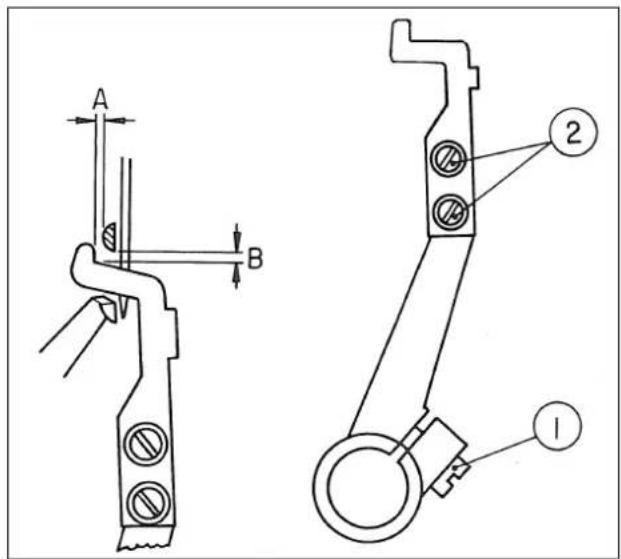
natural_image
Technical line drawing of a mechanical assembly with no visible text or symbolsnatural_image
Technical line drawing of a mechanical assembly with hoses, gears, and a motor (no text or symbols)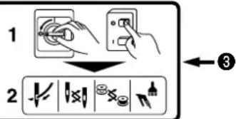
① Amount of oil (oil splashes) confirmation paper
② Position to confirm the amount of oil (oil splashes)

MH-481-4, MH-481-5, MH-484-4, MH-484-5


[MH-481-4, MH-481-5, MH-484-4, MH-484-5]
natural_image
Mechanical assembly diagram showing a clamping mechanism with no visible text or symbolsnatural_image
Technical line drawing of a mechanical assembly with no visible text or symbols[MH-481-4, MH-481-5, MH-484-4, MH-484-5]
natural_image
Technical line drawing of a mechanical assembly with no visible text or symbolsnatural_image
Technical line drawing of a mechanical clamp or bracket assembly with no visible text or symbolsnatural_image
Technical line drawing of a mechanical component with rotational arrow and base plate (no text or symbols)natural_image
Mechanical assembly diagram showing a lever mechanism with directional arrows (no text or labels)Elevador del pie-prensatela
natural_image
Technical line drawing of a mechanical assembly with no visible text or symbolsnatural_image
Technical line drawing of a mechanical assembly with no visible text or symbolsnatural_image
Simple line drawing of a basketball court with a ball, hoop, and target (no text or symbols)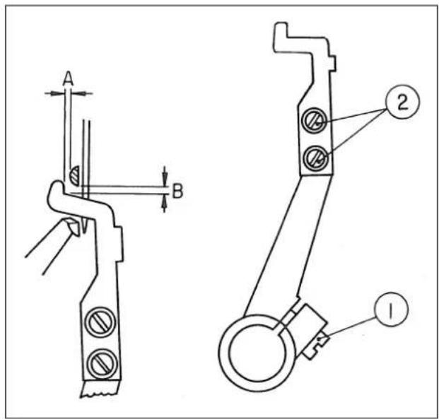
natural_image
Technical line drawing of a mechanical assembly with no visible text or symbolsS060 (Aditamento pára costuras recogidas)
natural_image
Technical line drawing of a mechanical assembly with hoses, gears, and housing (no text or symbols)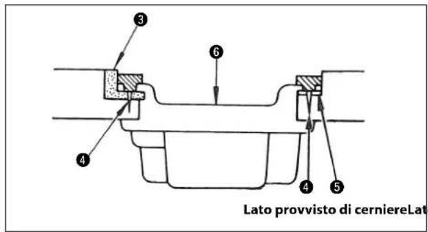
natural_image
Mechanical assembly diagram showing spring and housing components (no text or labels)
MH-481-4, MH-481-5, MH-484-4, MH-484-5


[MH-481-4, MH-481-5, MH-484-4, MH-484-5]
natural_image
Mechanical assembly diagram showing a gear mechanism with no visible text or symbolsnatural_image
Technical line drawing of a mechanical linkage or lifting device (no text or symbols)[MH-481-4, MH-481-5, MH-484-4, MH-484-5]

natural_image
Technical line drawing of a mechanical assembly with no visible text or symbolsnatural_image
Technical line drawing of a mechanical clamp or bracket assembly with no visible text or symbolsnatural_image
Technical line drawing of a mechanical component with rotational arrow and base plate (no text or symbols)natural_image
Mechanical assembly diagram showing a lever mechanism with directional arrows (no text or labels)Alzapiedino manuale
natural_image
Technical line drawing of a mechanical assembly with no visible text or symbolsPremicatenella
(MH-481, MH-481-4, MH-481-5)
natural_image
Technical line drawing of a mechanical assembly with no visible text or symbolsnatural_image
Simple line drawing of a vehicle with a circular head, a vertical pole, and a target symbol (no text or labels)