
LK-1941 - Sewing machine JUKI - Free user manual and instructions
Find the device manual for free LK-1941 JUKI in PDF.
| Product Type | Industrial Lockstitch Sewing Machine (Programmable) |
| Brand | Juki |
| Model | LK-1941 |
| Dimensions (with standard table) | 1200 mm (width) × 700 mm (length) × 1160 mm (height) |
| Total weight | Head: 46 kg, Control box: 16.5 kg, Heating element: 3.5 kg |
| Power supply | Rated voltage ±10%, 50/60 Hz, 600 W (single-phase or three-phase depending on version) |
| Maximum sewing speed | 2,200 stitches/min (with stitch length less than 3 mm) |
| Stitch length | 0.1 to 10.0 mm (adjustable in 0.1 mm increments) |
| Sewing area | X direction: 100 mm, Y direction: 60 mm |
| Needle bar stroke | 41.2 mm |
| Compatible needles | DP × 17, DP × 5 (DP × 17 installed at factory) |
| Hook | Full-rotary triple-capacity hook (lubricated) |
| Motor | Servo motor 550 W (direct drive) |
| Lubrication | New Defrix Oil No. 2 (daily filling by gauge) |
| Main functions | Storage of 99 patterns, X/Y scaling (20-200%), pause, thread break detection, piece and bobbin thread counter, built-in bobbin winder |
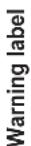
| Safety | Safety devices: motor cover, needle guard, eye guard cover, safety switch, warning labels |
| Maintenance and cleaning | Daily lubrication, filter cleaning, waste oil drain; always cut power before any intervention |
| Spare parts and repairability | Use exclusively JUKI parts; repairs by authorized technician |
| Operating environment | Temperature: 5 to 35 °C, Humidity: 35 to 85% (non-condensing) |
| Required air pressure | 0.5 to 0.55 MPa (for pneumatic options) |
Frequently Asked Questions - LK-1941 JUKI
User questions about LK-1941 JUKI
0 question about this device. Answer the ones you know or ask your own.
Ask a new question about this device
Download the instructions for your Sewing machine in PDF format for free! Find your manual LK-1941 - JUKI and take your electronic device back in hand. On this page are published all the documents necessary for the use of your device. LK-1941 by JUKI.
USER MANUAL LK-1941 JUKI
natural_image
Line drawing of a sewing machine on a workbench, no text or symbols present| NOTE: Read safety instructions carefully and understand them before using.Retain this Instruction Manual for future reference. |
| HINWEIS: Lesen Sie die Sicherheitsanweisungen aufmerksam durch, um sich mit ihnen vertraut zu machen, bevor Sie diese Maschine in Betrieb nehmen. Bewahren Sie diese Bedienungsanleitung für spätere Bezugnahme auf. |
| NOTE: Avant d’utiliser la machine, lire attentivement toutes les consignes de sécurité.Conserver ce manuel pour pouvior le consulter en cas de besoin. |
| NOTA: Antes de comenzar a usar esta máquina lea con detención hasta comprender todas las instrucciones de seguridad. Conserve este Manual de instrucciones a mano para futuras consultas. |
| NOTA: Leggere attentamente e compredere tutte le istruzioni per la sicurezza prima di inziare l’uso di questa macchina. Conservare questo Manuale d’Instruzioni per pronto riferimento. |
| 注意: 为了安全地使用,请您在使用之前一定阅读本使用说明书。另外,请您注意保管本使用说明书,以便随时查阅。 |
ENGLISH
TO ENSURE SAFE USE OF YOUR SEWING MACHINE
For the sewing machine, automatic machine and ancillary devices (hereinafter collectively referred to as "machine"), it is inevitable to conduct sewing work near moving parts of the machine. This means that there is always a possibility of unintentionally coming in contact with the moving parts. Operators who actually operate the machine and maintenance personnel who are involved in maintenance and repair of the machine are strongly recommended to carefully read to fully understand the following SAFETY PRECAUTIONS before using/maintaining the machine. The content of the SAFETY PRECAUTIONS includes items which are not contained in the specifications of your product.
The risk indications are classified into the following three different categories to help understand the meaning of the labels. Be sure to fully understand the following description and strictly observe the instructions.
( I ) Explanation of risk levels

DANGER :
This indication is given where there is an immediate danger of death or serous injury if the person in charge or any third party mishandles the machine or does not avoid the dangerous situation when operating or maintaining the machine.

WARNING :
This indication is given where there is a potentiality for death or serious injury if the person in charge or any third party mishandles the machine or does not avoid the dangerous situation when operating or maintaining the machine.

CAUTION :
This indication is given where there is a danger of medium to minor injury if the person in charge or any third party mishandles the machine or does not avoid the dangerous situation when operating or maintaining the machine.

Items requiring special attention.
(II) Explanation of pictorial warning indications and warning labels
| Pictorial warning indication |  | There is a risk of injury if contact-ing a moving section. | Pictorial warning indication | Be aware that holding the sewing machine during operation can hurt your hands. | |
 | There is a risk of electrical shock if contacting a high-voltage section. | There is a risk of entanglement in the belt resulting in injury. | |||
 | There is a risk of a burn if contact-ing a high-temperature section. | There is a risk of injury if you touch the button carrier. | |||
 | Be aware that eye deficiency can be caused by looking directly at the laser beam. | Indication label | The correct direction is indicated. | ||
 | There is a risk of contact between your head and the sewing ma-chine. | Connection of a earth cable is indicated. |


- There is the possibility that slight to serious injury or death may be caused.
- There is the possibility that injury may be caused by touching moving part.
② • To perform sewing work with safety guard. • To perform sewing work with safety cover. • To perform sewing work with safety protection device.
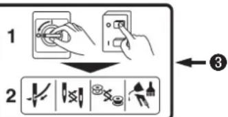
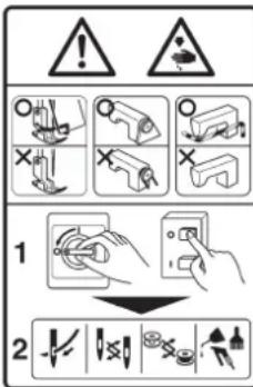
3 • Be sure to turn the power OFF before carrying out "machine-head threading", "needle changing", "bobbin changing" or "oiling and cleaning".
- When it is necessary to open the control box containing electrical parts, be sure to turn the power off and wait for five minutes or more before opening the cover in order to prevent accident leading to electrical shock.

CAUTION
Basic precaution
- Be sure to read the instruction manual and other explanatory documents supplied with accessories of the machine before using the machine. Carefully keep the instruction manual and the explanatory documents at hand for quick reference.
- The content of this section includes items which are not contained in the specifications of your product.
- Be sure to wear safety goggles to protect against accident caused by needle breakage.
- Those who use a heart pacer have to use the machine after consultation with a medical specialist.
Safety devices and warning labels
- Be sure to operate the machine after verifying that safety device(s) is correctly installed in place and works normally in order to prevent accident caused by lack of the device(s).
- If any of the safety devices is removed, be sure to replace it and verify that it works normally in order to prevent accident that can result in personal injury or death.
- Be sure to keep the warning labels adhered on the machine clearly visible in order to prevent accident that can result in personal injury or death. If any of the labels has stained or come unstuck, be sure to change it with a new one.
Application and modification
- Never use the machine for any application other than its intended one and in any manner other than that prescribed in the instruction manual in order to prevent accident that can result in personal injury or death. JUKI assumes no responsibility for damages or personal injury or death resulting from the use of the machine for any application other than the intended one.
- Never modify and alter the machine in order to prevent accident that can result in personal injury or death. JUKI assumes no responsibility for damages or personal injury or death resulting from the machine which has been modified or altered.
Education and training
- In order to prevent accident resulting from unfamiliarity with the machine, the machine has to be used only by the operator who has been trained/educated by the employer with respect to the machine operation and how to operate the machine with safety to acquire adequate knowledge and operation skill. To ensure the above, the employer has to establish an education/training plan for the operators and educate/train them beforehand.
Items for which the power to the machine has to be turned off
Turning the power off: Turning the power switch off, then removing the power plug from the outlet. This applies to the following.
- Be sure to immediately turn the power off if any abnormality or failure is found or in the case of power failure in order to protect against accident that can result in personal injury or death.
- To protect against accident resulting from abrupt start of the machine, be sure to carry out the following operations after turning the power off. For the machine incorporating a clutch motor, in particular, be sure to carry out the following operations after turning the power off and verifying that the machine stops completely.
2-1. For example, threading the parts such as the needle, looper, spreader etc. which have to be threaded, or changing the bobbin.
2-2. For example, changing or adjusting all component parts of the machine.
2-3. For example, when inspecting, repairing or cleaning the machine or leaving the machine.
-
Be sure to remove the power plug by holding the plug section instead of the cord section in order to prevent electrical-shock, earth-leakage or fire accident.
-
Be sure to turn the power off whenever the machine is left unattended between works.
-
Be sure to turn the power off in the case of power failure in order to prevent accident resulting of breakage of electrical components.
PRECAUTIONS TO BE TAKEN IN VARIOUS OPERATION STAGES
Transportation
- Be sure to lift and move the machine in a safe manner taking the machine weight in consideration. Refer to the text of the instruction manual for the mass of the machine.
- Be sure to take sufficient safety measures to prevent falling or dropping before lifting or moving the machine in order to protect against accident that can result in personal injury or death.
- Once the machine has been unpacked, never re-pack it for transportation to protect the machine against breakage resulting from unexpected accident or dropping.
Unpacking
- Be sure to unpack the machine in the prescribed order in order to prevent accident that can result in personal injury or death. In the case the machine is crated, in particular, be sure to carefully check nails. The nails have to be removed.
- Be sure to check the machine for the position of its center of gravity and take it out from the package carefully in order to prevent accident that can result in personal injury or death.
Installation
(I) Table and table stand
- Be sure to use JUKI genuine table and table stand in order to prevent accident that can result in personal injury or death. If it is inevitable to use a table and table stand which are not JUKI genuine ones, select the table and table stand which are able to support the machine weight and reaction force during operation.
- If casters are fitted to the table stand, be sure to use the casters with a locking mechanism and lock them to secure the machine during the operation, maintenance, inspection and repair in order to prevent accident that can result in personal injury or death.
(II) Cable and wiring
- Be sure to prevent an extra force from being applied to the cable during the use in order to prevent electrical-shock, earth-leakage or fire accident. In addition, if it is necessary to cable near the operating section such as the V-belt, be sure to provide a space of 30 mm or more between the operating section and the cable.
- Be sure to avoid starburst connection in order to prevent electrical-shock, earth-leakage or fire accident.
- Be sure to securely connect the connectors in order to prevent electrical-shock, earth-leakage or fire accident. In addition, be sure to remove the connector while holding its connector section.
(III) Grounding
- Be sure to have an electrical expert install an appropriate power plug in order to prevent accident caused by earth-leakage or dielectric strength voltage fault. In addition, be sure to connect the power plug to the grounded outlet without exceptions.
- Be sure to ground the earth cable in order to prevent accident caused by earth leakage.
(IV) Motor
- Be sure to use the specified rated motor (JUKI genuine product) in order to prevent accident caused by burnout.
- If a commercially available clutch motor is used with the machine, be sure to select one with an entanglement preventive pulley cover in order to protect against being entangled by the V-belt.
Before operation
- Be sure to make sure that the connectors and cables are free from damage, dropout and looseness before turning the power on in order to prevent accident resulting in personal injury or death.
- Never put your hand into the moving sections of the machine in order to prevent accident that can result in personal injury or death.
In addition, check to be sure that the direction of rotation of the pulley agrees with the arrow shown on pulley. - If the table stand with casters is used, be sure to secure the table stand by locking the casters or with adjusters, if provided, in order to protect against accident caused by abrupt start of the machine.
During operation
- Be sure not to put your fingers, hair or clothing close to the moving sections such as the handwheel, hand pulley and motor or place something near those sections while the machine is in operation in order to prevent accident caused by entanglement that can result in personal injury or death.
- Be sure not to place your fingers near the surround area of the needle or inside the thread take-up lever cover when turning the power on or while the machine is in operation in order to prevent accident that can result in personal injury or death.
- The machine runs at a high speed. Never bring your hands near the moving sections such as looper, spreader, needle bar, hook and cloth trimming knife during operation in order to protect your hands against injury. In addition, be sure to turn the power off and check to be sure that the machine completely stops before changing the thread.
-
Be careful not to allow your fingers or any other parts of your body to be caught between the machine and table when removing the machine from or replacing it on the table in order to prevent accident that can result in personal injury or death.
-
Be sure to turn the power off and check to be sure that the machine and motor completely stop before removing the belt cover and V-belt in order to prevent accident caused by abrupt start of the machine or motor.
- If a servomotor is used with the machine, the motor does not produce noise while the machine is at rest. Be sure not to forget to turn the power off in order to prevent accident caused by abrupt start of the motor.
- Never use the machine with the cooling opening of the motor power box shielded in order to prevent fire accident by overheat.
Lubrication
- Be sure to use JUKI genuine oil and JUKI genuine grease to the parts to be lubricated.
- If the oil adheres on your eye or body, be sure to immediately wash it off in order to prevent inflammation or irritation.
- If the oil is swallowed unintentionally, be sure to immediately consult a medical doctor in order to prevent diarrhea or vomiting.
Maintenance
- In prevention of accident caused by unfamiliarity with the machine, repair and adjustment has to be carried out by a service technician who is thoroughly familiar with the machine within the scope defined in the instruction manual. Be sure to use JUKI genuine parts when replacing any of the machine parts. JUKI assumes no responsibility for any accident caused by improper repair or adjustment or the use of any part other than JUKI genuine one.
- In prevention of accident caused by unfamiliarity with the machine or electrical-shock accident, be sure to ask an electrical technician of your company or JUKI or distributor in your area for repair and maintenance (including wiring) of electrical components.
- When carrying out repair or maintenance of the machine which uses air-driven parts such as an air cylinder, be sure to remove the air supply pipe to expel air remaining in the machine beforehand, in order to prevent accident caused by abrupt start of the air-driven parts.
- Be sure to check that screws and nuts are free from looseness after completion of repair, adjustment and part replacement.
- Be sure to periodically clean up the machine during its duration of use. Be sure to turn the power off and verify that the machine and motor stop completely before cleaning the machine in order to prevent accident caused by abrupt start of the machine or motor.
- Be sure to turn the power off and verify that the machine and motor stop completely before carrying out maintenance, inspection or repair of the machine. (For the machine with a clutch motor, the motor will keep running for a while by inertia even after turning the power off. So, be careful.)
- If the machine cannot be normally operated after repair or adjustment, immediately stop operation and contact JUKI or the distributor in your area for repair in order to prevent accident that can result in personal injury or death.
- If the fuse has blown, be sure to turn the power off and eliminate the cause of blowing of the fuse and replace the blown fuse with a new one in order to prevent accident that can result in personal injury or death.
- Be sure to periodically clean up the air vent of the fan and inspect the area around the wiring in order to prevent fire accident of the motor.
Operating environment
- Be sure to use the machine under the environment which is not affected by strong noise source (electromagnetic waves) such as a high-frequency welder in order to prevent accident caused by malfunction of the machine.
- Never operate the machine in any place where the voltage fluctuates by more than "rated voltage ± 10% in order to prevent accident caused by malfunction of the machine.
- Be sure to verify that the air-driven device such as an air cylinder operates at the specified air pressure before using it in order to prevent accident caused by malfunction of the machine.
- To use the machine with safety, be sure to use it under the environment which satisfies the following conditions:
Ambient temperature during operation 5°C to 35°C
Relative humidity during operation 35 % to 85 %
- Dew condensation can occur if bringing the machine suddenly from a cold environment to a warm one. So, be sure to turn the power on after having waited for a sufficient period of time until there is no sign of water droplet in order to prevent accident caused by breakage or malfunction of the electrical components.
- Be sure to stop operation when lightning flashes for the sake of safety and remove the power plug in order to prevent accident caused by breakage or malfunction of the electrical components.
- Depending on the radio wave signal condition, the machine may generate noise in the TV or radio. If this occurs, use the TV or radio with kept well away from the machine.
- In order to ensure the work environment, local laws and regulations in the country where the sewing machine is installed shall be followed. In the case the noise control is necessary, an ear protector or other protective gear should be worn according to the applicable laws and regulations.
- Disposal of products and packages and treatment of used lubricating oil should be carried out properly according to the relevant laws of the country in which the sewing machine is used.
Precautions to be taken so as to use the LK-1941, LK-1942 more safely
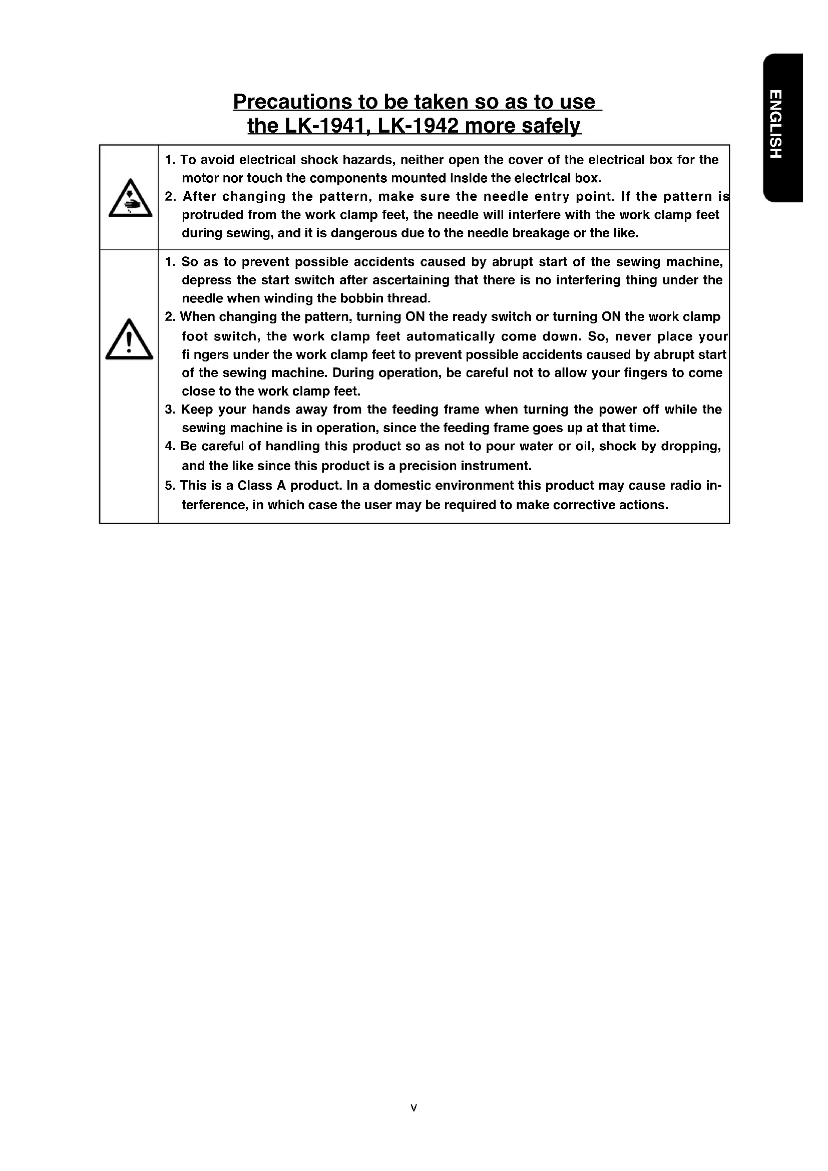
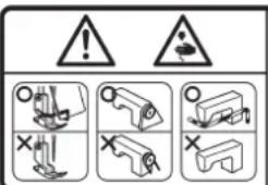
| 1. To avoid electrical shock hazards, neither open the cover of the electrical box for the motor nor touch the components mounted inside the electrical box.2. After changing the pattern, make sure the needle entry point. If the pattern is protruded from the work clamp feet, the needle will interfere with the work clamp feet during sewing, and it is dangerous due to the needle breakage or the like. | |
| 1. So as to prevent possible accidents caused by abrupt start of the sewing machine, depress the start switch after ascertaining that there is no interfering thing under the needle when winding the bobbin thread.2. When changing the pattern, turning ON the ready switch or turning ON the work clamp foot switch, the work clamp feet automatically come down. So, never place your fingers under the work clamp feet to prevent possible accidents caused by abrupt start of the sewing machine. During operation, be careful not to allow your fingers to come close to the work clamp feet.3. Keep your hands away from the feeding frame when turning the power off while the sewing machine is in operation, since the feeding frame goes up at that time.4. Be careful of handling this product so as not to pour water or oil, shock by dropping, and the like since this product is a precision instrument.5. This is a Class A product. In a domestic environment this product may cause radio interference, in which case the user may be required to make corrective actions. |
Safety devices and warning labels

CAUTION
In addition, be aware that the safety devices such as the "eye protection cover" and "finger guard" are sometimes omitted in the sketches, illustrations and figures included in the Instruction Manual for the explanation's sake. In the practical use, never remove those safety devices.
DECLARATION OF INCORPORATION OF PARTLY COMPLETED MACHINERY
We hereby declare that the sewing machine (sewing head) described below ;
- Must not be put into service until the machinery to which it is incorporated has been declared in conformity with the provisions of the Directive 2006/42/EC, and
- Conforms to the essential requirements of the Directive 2006/42/EC, described in the technical documentation, and
- To be prepared with the above technical documentation compiled in accordance with part B of Annex VII, and
- Also to conform to the RoHS Directive 2011/65/EU
- Relevant information on which should be transmitted in response to a reasoned request by the national authorities, by the electronic method or other according to the request.
Model LK-1941, LK-1942
Description Industrial Sewing Machine
Function make stitches and sew
Applied harmonized standards, in particular :
EN ISO12100, EN 60204-31, EN ISO10821, EN 50581
Manufacturer :
JUKI CORPORATION
2-11-1, Tsurumaki, Tama-shi, Tokyo, Japan
CONTENTS
I. SPECIFICATIONS....1
II. CONFIGURATION 2
- Names of main unit .... 2
- Names of switches on the control box .... 3
III. INSTALLATION 4
IV. OPERATION OF THE SEWING MACHINE.... 18
- Lubrication.... 18
- Attaching the needle 19
- Threading the machine head 20
- Installing and removing the bobbin case .... 21
- Installing the bobbin 21
- Adjusting the thread tension 22
- Adjusting the thread take-up spring 22
- Adjusting the height of the intermediate presser (for LK-1942 only) 23
- Adjusting the intermediate presser stroke (for LK-1942 only) 23
V. OPERATION OF THE SEWING MACHINE (BASIC) 25
- Item data setting 25
- Checking the contour of a sewing pattern 27
- Sewing 28
- Change to the other sewing pattern 29
- Temporarily stopping the sewing machine 29
- Winding the bobbin thread 30
- Cautions in operation 31
VI. OPERATION OF THE SEWING MACHINE (ADVANCED) 32
- Performing sewing using the pattern keys ( P1 , P2 and P3 keys) 32
- Performing sewing using the combination function 34
- Performing sewing using the "bobbin thread counter" 36
- How to take out the sewing products when the thread cutting failure has occurred (for Z type only) .... 37
VII. MAINTENANCE 38
- Adjusting the height of the needle bar 38
- Adjusting the needle-to-shuttle relation 38
- Adjusting the height of the feeding frame 41
- Adjusting the rising amount of the thread tension disk 41
- The moving knife and counter knife 42
- Thread breakage detector plate 44
- Adjusting the amount of oil in the hook 45
- Cleaning the filter 46
- Draining waste oil 46
- Replacing the fuse 47
VIII. HOW TO USE THE MEMORY SWITCH 48
- Starting the memory switch 48
- Example of the memory switch setting 48
- Table of functions of the memory switch 50
IX. OTHERS 52
- Sewing pattern 52
- Setting the DIP switch 54
- Connection of the optional pedal 55
- Table of error indication .... 57
- Troubles and corrective measures (sewing conditions) 58
- The optional parts .... 59
- Table of the gauge parts 62
- Drawing of the table 63
I. SPECIFICATIONS
1) Sewing area : X (lateral) direction 100 mm Y (longitudinal) direction 60 mm
2) Max. sewing speed : * 2,200 sti/min (When sewing pitch is less than 3 mm.)
3) Stitch length : 0.1 to 10.0 mm (adjustable in 0.1 mm step)
4) Feed motion of work clamp foot : Intermittent feed (2-shaft drive by stepping motor)
5) Needle bar stroke : 41.2 mm
6) Needle : DP x 17, DP x 5 (DP x 17 is attached at the time of delivery.)
7) Lift of feeding frame : 18 mm (standard) Max. 25 mm
8) Hook : Full-rotary three-fold capacity hook
9) Intermediate presser stroke : 4 mm (standard) (Adjustable in the range of 0 and 4 to 10 mm) (For LK-1942 only)
10) Lift of intermediate presser : 18 mm (For LK-1942 only)
11) Lubricating oil : New Defrix Oil No. 2 (supplied by oiler)
12) Data recording : EEP-ROM (32k byte)
13) Enlarging/Reducing facility : Allows a pattern to be enlarged or reduced on the X axis and Y axis independently when sewing a pattern
Scale : 20% to 200% (1% step)
14) Enlarging/Reducing method : Pattern enlargement / reduction can be done by increasing/decreasing the stitch length
15) Temporary stop function : Used to stop machine operation during a stitching cycle.
16) Thread breakage detection function : Used to detect needle thread breakage to automatically stop machine.
17) Max. sewing speed limitation : The max. sewing speed can be set limited to any value within a range of 200 to 2,200 sti/min using the up/down key. (100 sti/min steps)
18) Pattern selection : 1 to 99 patterns can be selected by specifying the desired pattern Nos.
19) Bobbin thread counter : Tells the time to replace the bobbin by the bobbin thread counter. (Max. 9,999 pcs.)
20) Production counter : Displays the number of pieces of production by the production counter. (Max. 9,999 pcs.)
21) Memory back-up : In case of a power interruption, the pattern being used will automatically be stored in memory.
22) Sewing machine motor : 550W servo motor (Direct-drive)
23) Dimensions : W : 1,200 mm L : 700 mm H : 1,160 mm (Use the standard table and stand.)
24) Weight : Machine head 46 kg, Control box 16.5 kg, Heater unit 3.5 kg
25) Power consumption : 600 W
26) Operating temperature range : 5 °C to 35 °C
27) Operating humidity range : 35% to 85% (No dew condensation)
28) Line voltage : Rated voltage ± 10% 50/60 HZ
29) Air pressure used : 0.5 to 0.55 MPa {5 to 5.5 kgf/cm ^2 }
30) Air consumption : 1.3 ℓ /min
31) Needle bar reverse rotation stop function : After the completion of sewing, the needle can be stopped in its upper position by rotating the needle bar in the reverse direction.
* Reduce the max. sewing speed in accordance with the sewing conditions.
* To select and use either the bobbin thread counter or the production counter.
32) Noise : - Equivalent continuous emission sound pressure level ( L_pA ) at the workstation :
A-weighted value of 79.5 dB; (Includes K_pA = 2.5 dB); according to ISO 10821-C.6.3-ISO 11204 GR2 at 2,200 sti/min.
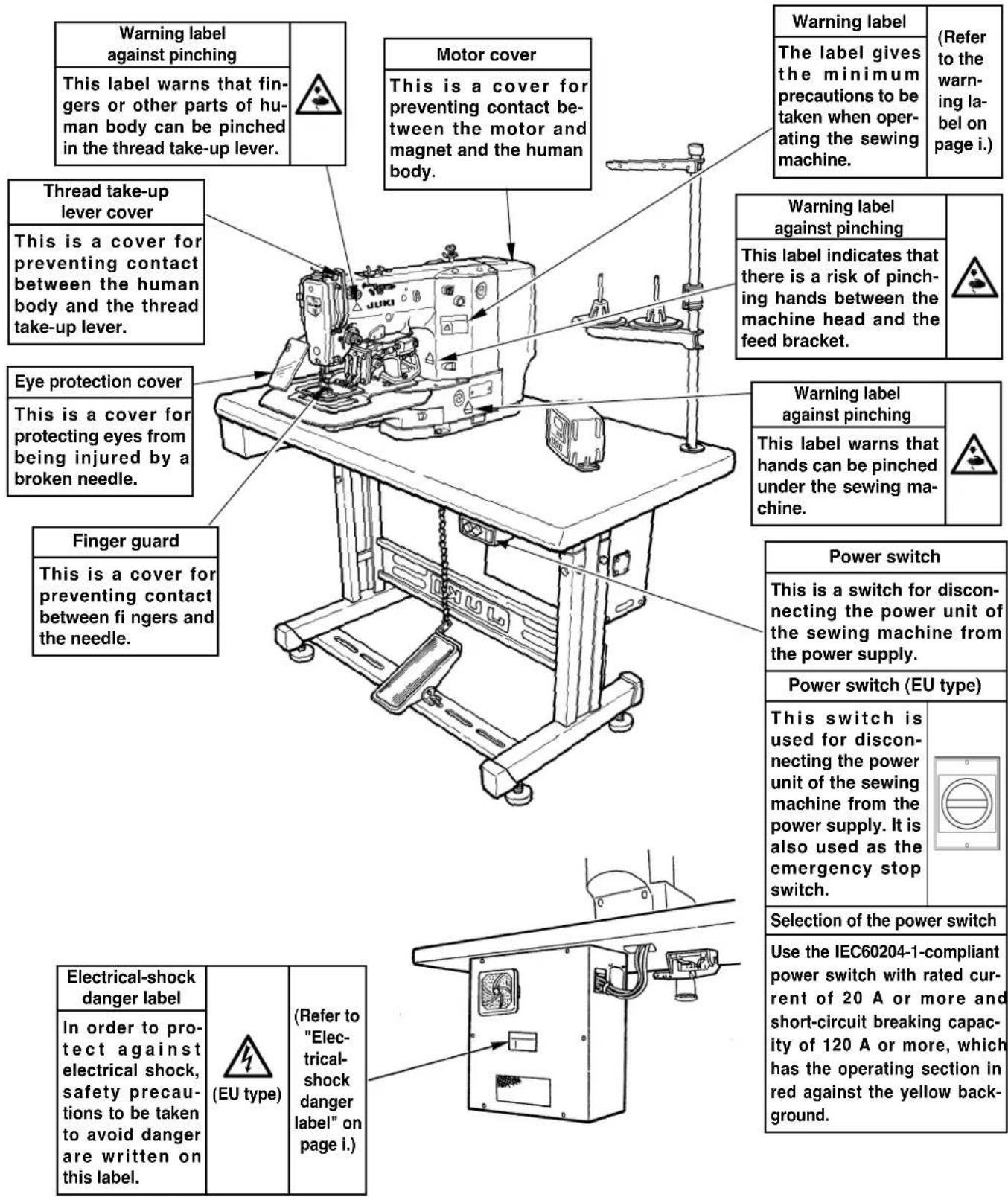
II. CONFIGURATION
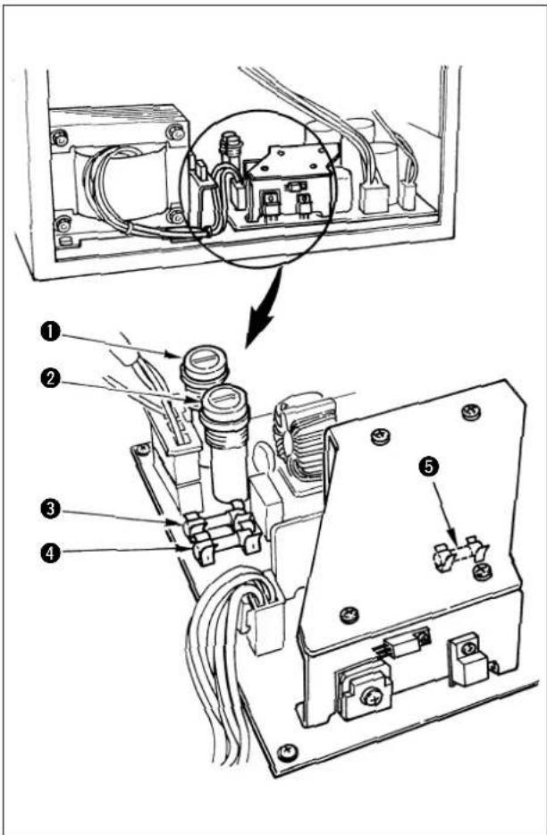
1. Names of main unit
Air regulator
natural_image
Technical line drawing showing a mechanical assembly with wiring and a close-up view of a component (no text or symbols)2. Names of switches on the control box
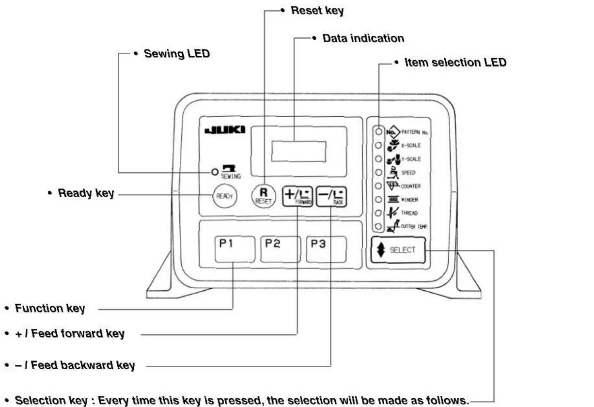
- Pattern No. → X Scale → Y Scale → Speed → Counter → Bobbin winder → Threading → Heat cutter temperature (For Z type only)
III. INSTALLATION

WARNING :
To prevent possible accidents caused by the fall of the sewing machine, perform the work by two persons or more when the machine is moved.
(1) Set-up of the table
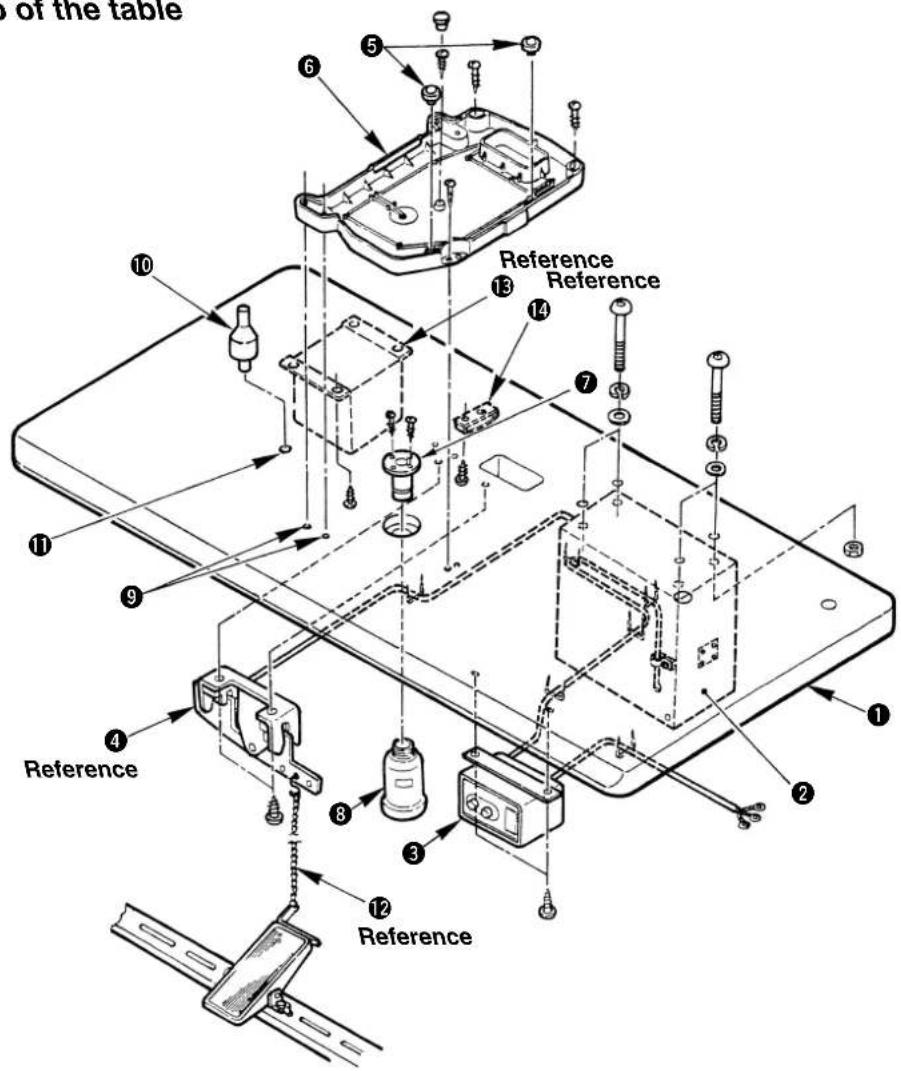
1) Securely install control box ②, power switch ③, pedal switch ④, heater unit ⑬ and cable clamp ⑭ on table (14117519) ①.
2) Connect the pedal with ④ the pedal switch using the chain ⑫.
3) Securely fix the respective power cables with the staples.
4) Securely fix oil drain ⑦ on the table ①, and screw oil receiver ⑧.
5) Set cushion rubber ⑤ on oil pan ⑥, and fit oil pan ⑥ to the holes of the table hinges (4 places) ⑨. Then fix oil pan ⑥ at 4 places with wood screws.
6) Close the center portion of oil pan ⑥ with the rubber plug after screwing it.
7) Strike head support bar ⑩ in the hole of table ⑪.

-
Installation of ④ and ⑫ is for 1-pedal type only.
-
Installation of ⑬ and ⑭ is for Z type only.
(2) Connecting the power source cord
• Voltage specifications
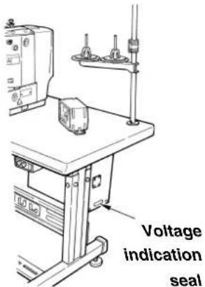
Power source specifications are indicated on the voltage indication seal. Connect the cord in accordance with the specifications.
| Specification Voltage | Indication Seal | Voltage indication seal | |
| Three phase 200V | 3ø 200V | Three phase 220V | 3ø 220V |
| Three phase 240V | 3ø 240V | Single phase 200V | 1ø 200V |
| Three phase 380V | 3ø 380V | Single phase 220V | 1ø 220V |
| Three phase 400V | 3ø 400V | Single phase 230V/240V | 1ø 240V |
| Three phase 415V | 3ø 415V |
- Connecting single phase 200V, 220V, 230V and 240V
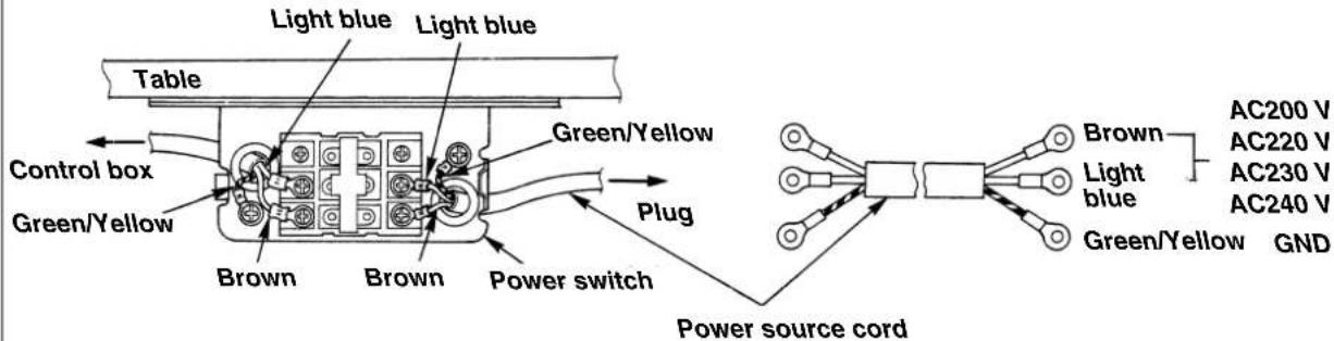
- Connecting three phase 200V, 220V, 240V, 380V, 400V and 415V
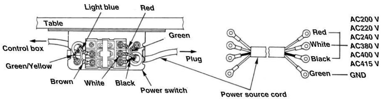
WARNING :
- Never use under the wrong voltage and phase.
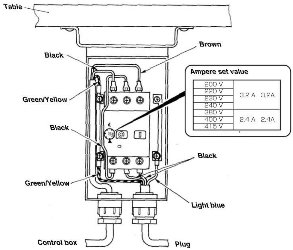
- When changing the voltage to be used :
Refer to the item "Changing the voltage between 100 and 240V" for the following specifications.
1 ∅200V, 1 ∅220V, 1 ∅240V,
3 0200V, 3 0220V and 3 0240V
Refer to the item "Changing the voltage between 220 and 415V" for the following specifications.
3 ∅220V, 3 ∅240V, 3 ∅380V, 3 ∅400V, and 3 ∅415V

(3) Power switch
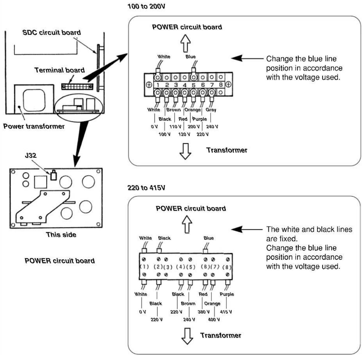
(4) Changing the voltage
Changing the voltage between 100 and 240V
When the voltage of 100V or 200V is supplied, following voltages can be used by changing the terminal board.
| Line color (White) Line color (Blue) Input voltage Remarks | |||
| Terminal board No. | |||
| 1 2 100 | |||
| 1 3 110 With | J32 connector | ||
| 1 4 120 | |||
| 1 5 200 | |||
| 1 6 220 Without J32 connector | |||
| 1 7 230/240 | |||

Voltage change : 100V ←→ 200V
When voltage of 100V, 110V or 120V is used, it is necessary to connect the voltage change cord (Part No. M90215800A0) to J32 connector mounted on the POWER circuit board.
When voltage of 200V, 220V, 230V or 240V is used, do not install J32 connector. If the setting of J32 connector is mistaken, the control box is likely to be broken.
Changing the voltage between 220V and 415V
When the voltage from 220V to 415V is supplied, following voltages can be used by changing the terminal board.
| Line color (White) Line color (Black) Line color (Blue) Input voltage | |||
| Terminal board No. | |||
| 1 2 4 220 | |||
| 1 2 5 230/240 | |||
| 1 2 6 380 | |||
| 1 2 7 400 | |||
| 1 2 8 415 | |||
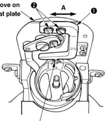
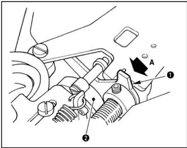
(5) Fixing the sewing machine main unit
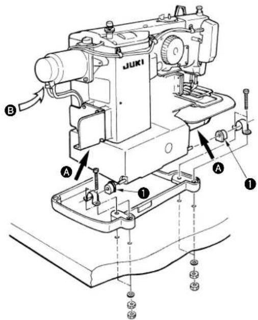
Fit hinge rubber ① to the hinge shaft, and fix the sewing machine main unit.

Hold section A when moving the sewing machine.
In addition, do not hold motor portion B.

WARNING :
To prevent possible accidents caused by the fall of the sewing machine, perform the work by two persons or more when the machine is moved.
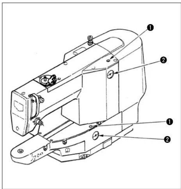
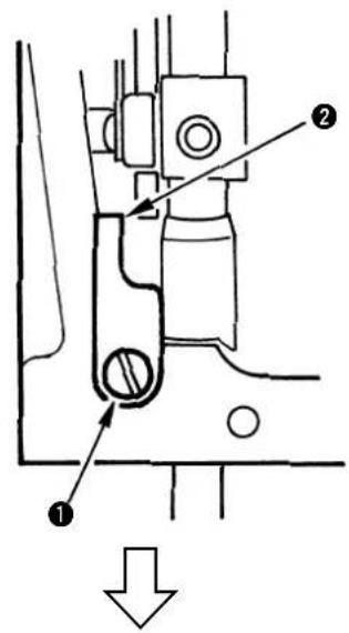
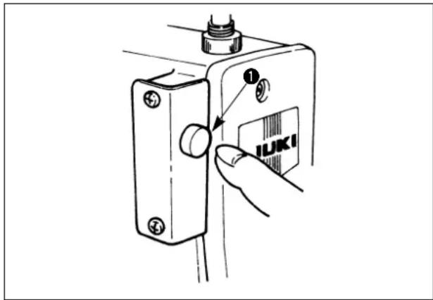
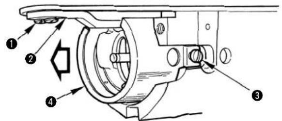
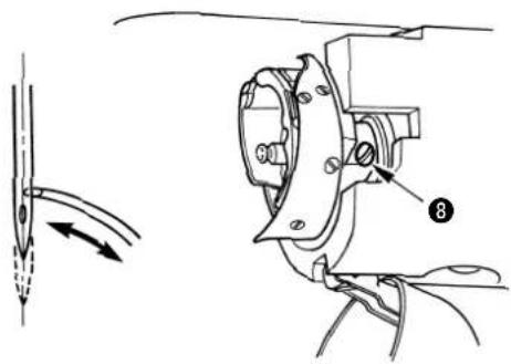
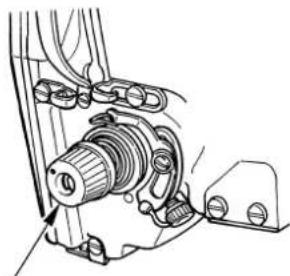
(6) Setting the safety switch
The safety switch is provided so that the sewing machine does not rotate when it is tilted for maintenance or inspection.
Properly set the switch at the correct position when installing the sewing machine.
(If the switch is not set to the correct position, the sewing machine cannot be operated.)
1) Loosen two setscrews ①.
2) Lower safety switch ② to the bottom.
3) Tighten two setscrews ①.
(7) Installing the motor cover
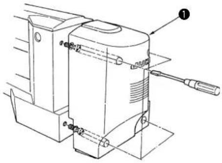
Install motor cover ① to the sewing machine main unit using the screws set in the cover.
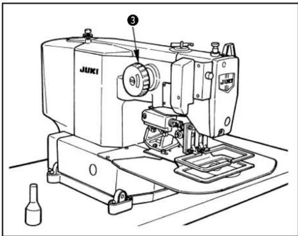
(8) Installing the operation box
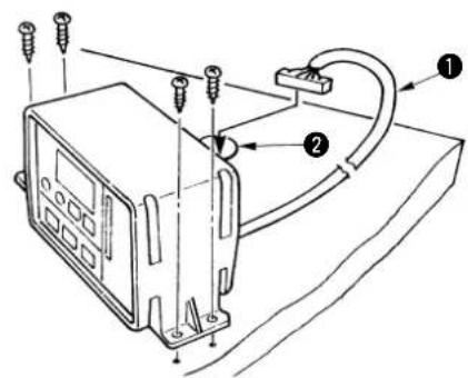
Pass operation box cable ① into table hole ②, and fix the operation box.
(9) Pedal switch
• 1-pedal
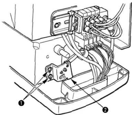
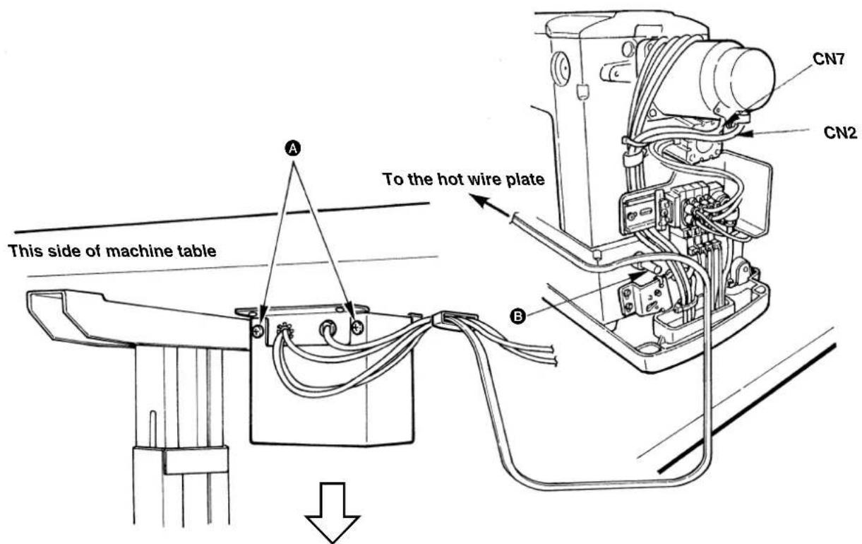
(10) Connecting the cords
Perform the connection of the cords as shown in the figure below.
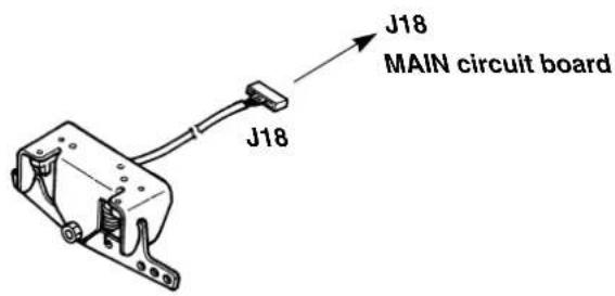
Bundle CN2 and CN7 together with other cords using cable band B so that they do not come in contact with Y feed shaft A. Pass the cords of J12, 14, 15, 59 and through the cord clamp A located on the upper side of the inside of the control box and the cords of J17, 18 and (26) through the cord clamp B. Bundle J2, 8 and FG using the cable band.
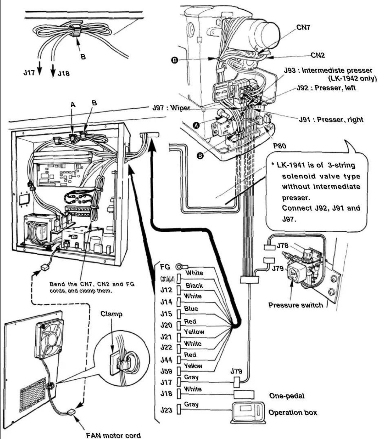

-
Bend and clamp J17 and J18 cords as shown in the figure above.
-
Remove the fan motor cord from the clamp when opening the cover.
In addition, wind the cord on the clamp when attaching the cover.
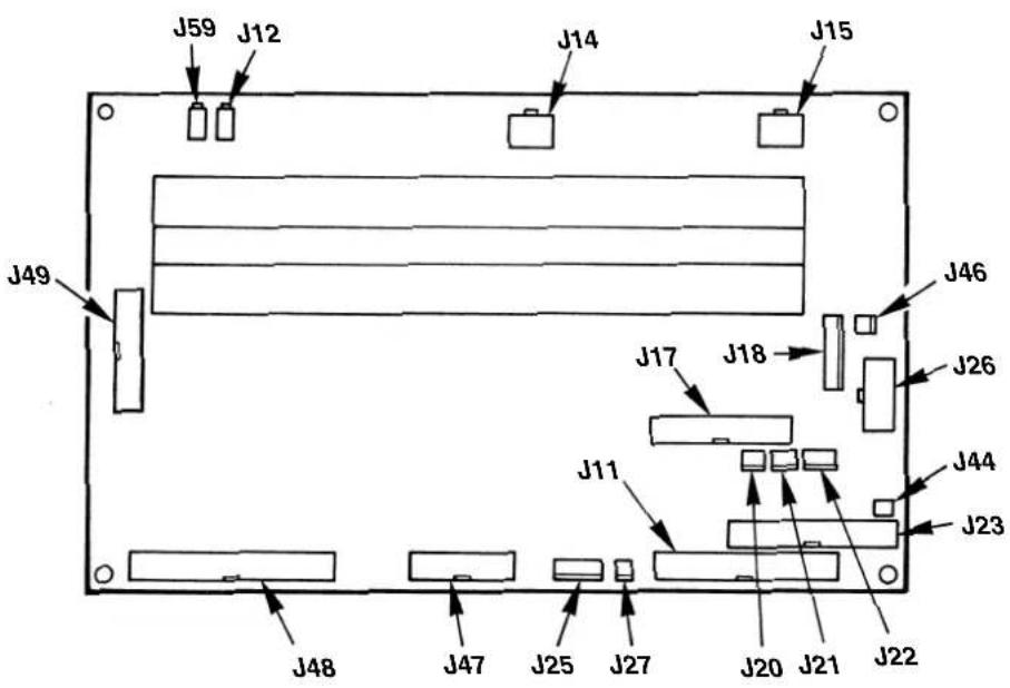
○ Position of MAIN circuit board connectors
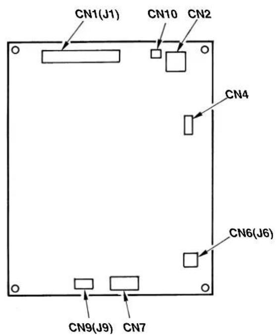
○ Position of SDC circuit board connectors
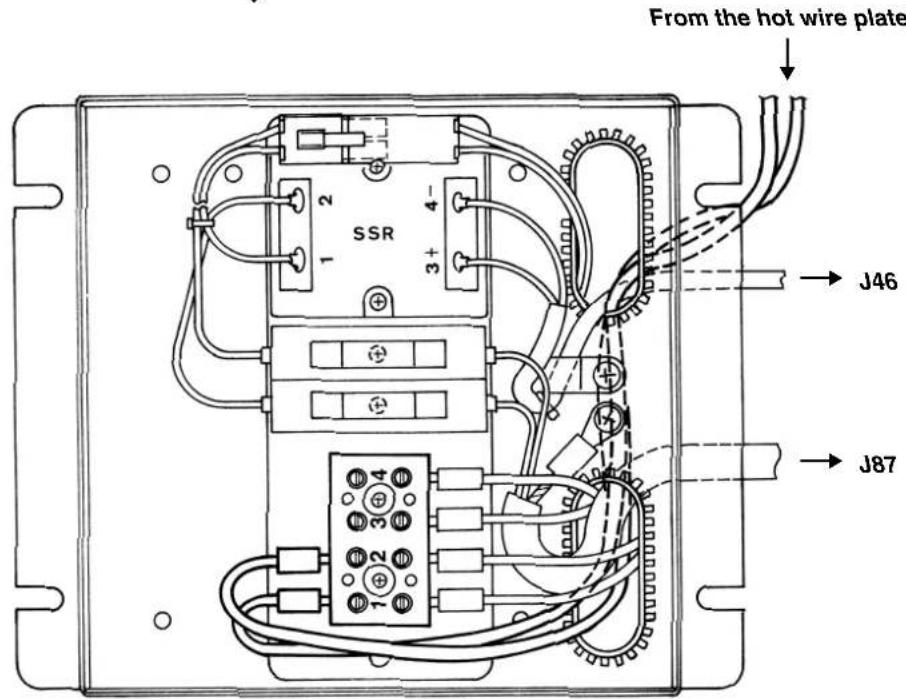
(11) Connecting the heater unit (For Z type only)
1) Remove four screws Ⓐ and remove the heater unit cover.
2) Pass the cables and connect them to terminal board 1 and 2 as shown in the figure below.
(Be careful that the cable does not come in contact with Y feed shaft B.)
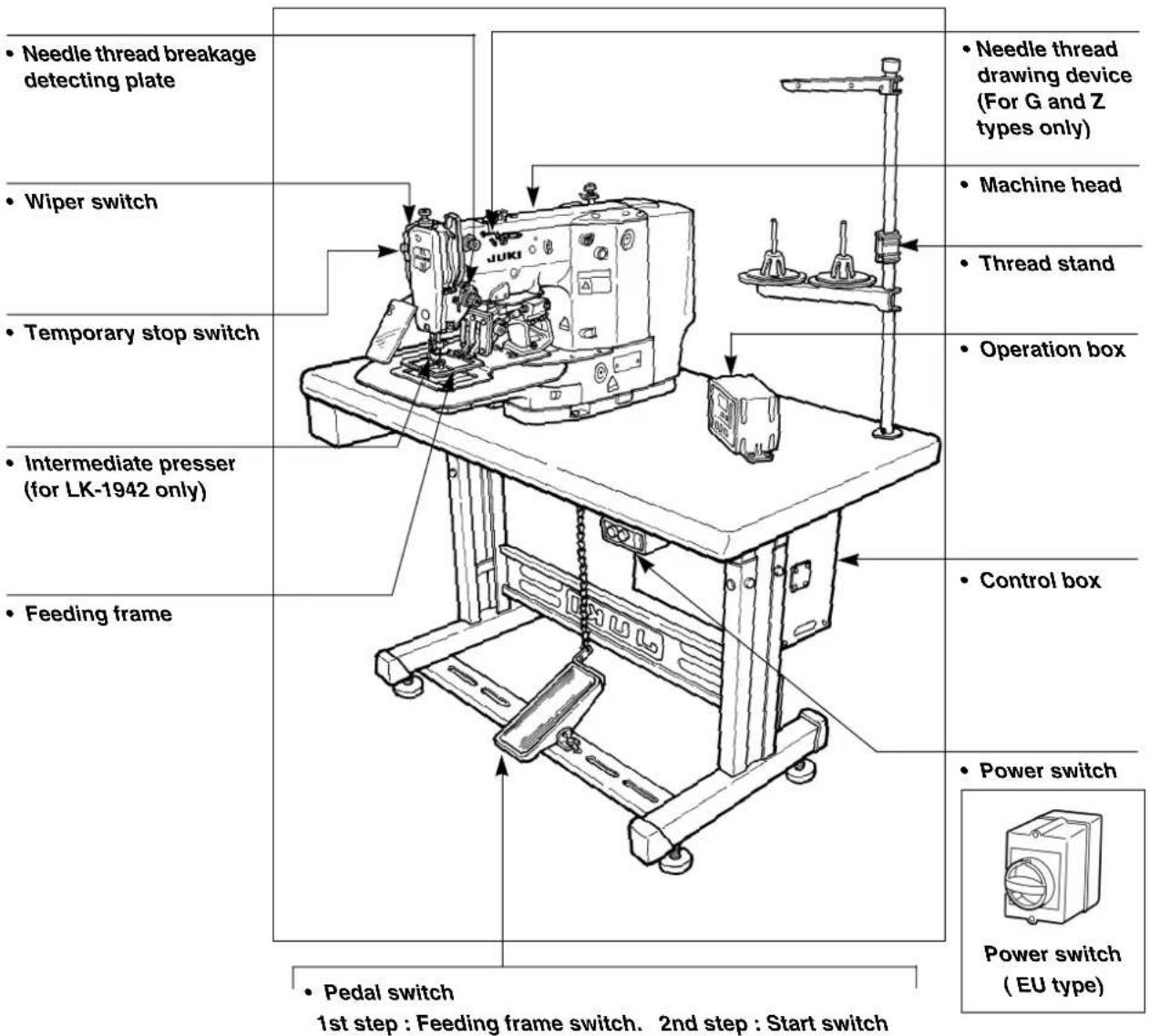
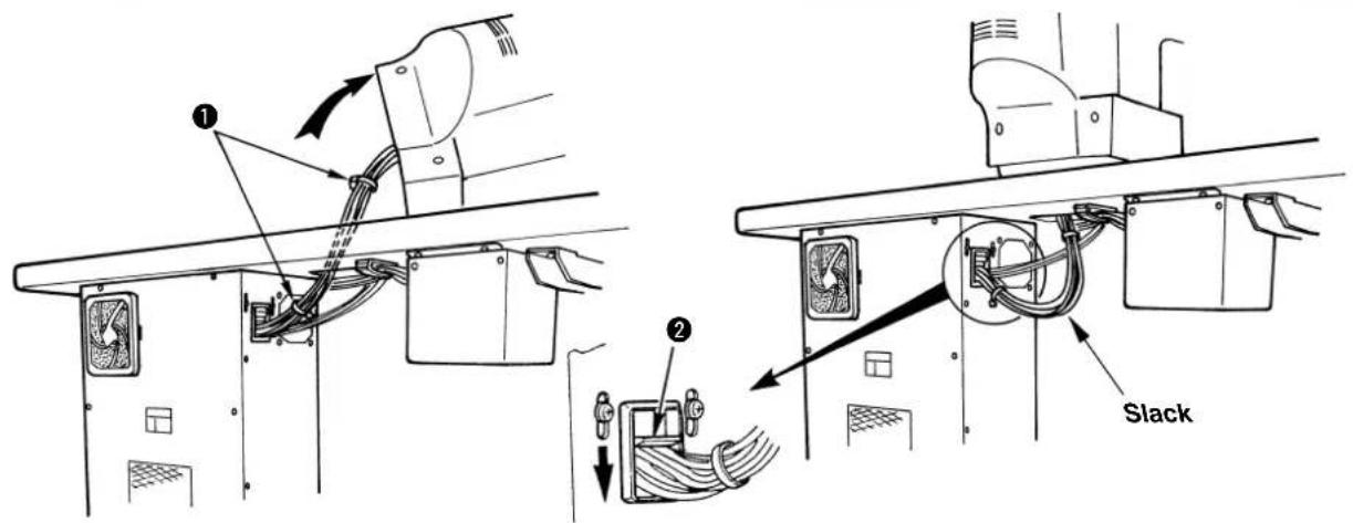
(12) Managing the cord
1) In the state that the sewing machine is tilted, connect the cords, and bundle them with clip band ① as shown in the figure.
2) Fix the cords with cords setting plate ② in the state that the cords slacken as shown in the figure.

When you tilt the sewing machine, make sure that the sewing machine head support bar is placed on the table.
(13) Connecting the air hose
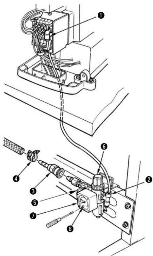
1) Cut the air tube supplied with the machine in an appropriate length, and connect solenoid vsalve ① with air regulator ②.
2) Connect the air source hose using one-touch joint ③ and hose band ④ supplied with the machine.
3) Open air cock ⑤ and adjust the air pressure to 0.5 to 0.55 MPa {5 to 5.5 kgf/cm²} by pulling up and turning adjustment knob ⑥ of the air regulator while observing air pressure gauge ⑦.
4) Turn knob ⑧ located in front of the air regulator using a small screwdriver and adjust the pressure switch to 0.4 MPa 4kgf/cm^2 .
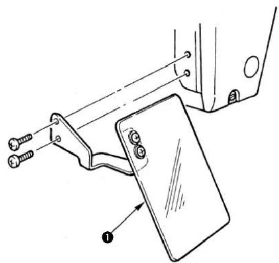
(14) Installing the eye protection cover

WARNING :
Be sure to attach this cover to protect the eyes from the disperse of needle breakage.
natural_image
Technical line drawing of a mechanical assembly with labeled parts (no text or symbols present)Be sure to install and use eye protection cover ①.
(15) Installing the thread stand
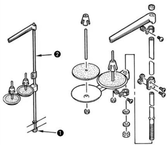
1) Assemble the thread stand, and set it in the hole in the top right corner of the machine table.
2) Tighten locknut ① to fix the thread stand.
3) When ceiling wiring is possible, pass the power cord through spool rest rod ②.
(16) Installing the auxiliary throat plate cover
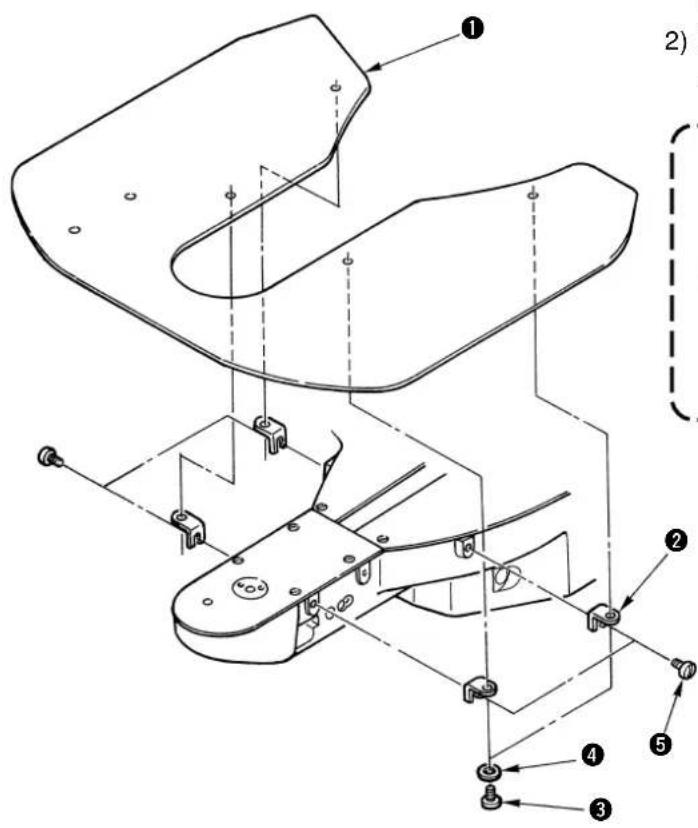
1) Install the auxiliary throat plate cover support ② to auxiliary throat plate cover ① using setscrew ③ (L=6) and washer ④.
2) Install the cover on the machine arm using attaching screw ⑤(L=8).

Adjust so that the auxiliary throat plate cover should be almost levelled with the throat plate. If there is a difference in height, the feed plate may be caught with the auxiliary throat plate cover.
(17) Attaching the bolt for transportation
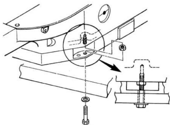
When transporting the sewing machine, fix the sewing machine main unit with the bolt for transportation.
(18) Tilting the sewing machine head

WARNING :
When tilting/raising the sewing machine head, perform the work so as not to allow your fingers to be caught in the machine. In addition, to avoid possible accidents caused by abrupt start of the machine, turn OFF the power to the machine before starting the work.
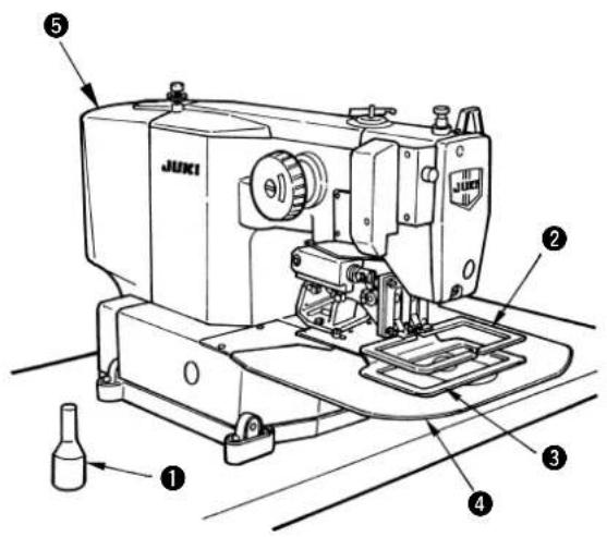
When tilting the sewing machine head, tilt the head gently until head support rod ① comes in contact with the head.

-
Make sure that head support rod ① is attached to the machine table before tilting the sewing machine head.
-
When the sewing machine head is tilted, feeding frame ② moves to the left side by itself and interferes with the intermediate presser or the like. As a result, it will be the cause of breakage. Remove the aforementioned component in advance, or fix feed plate ③ to throat plate support cover ④ with tape or the like, and tilt the sewing machine head.
-
When tilting the sewing machine head while holding motor cover ⑤ and throat plate support cover ④, the covers may be bent. Be sure to tilt the sewing machine head while holding the main unit of the sewing machine.
-
Be sure to tilt the sewing machine head on a flat place to prevent it from falling.
IV. OPERATION OF THE SEWING MACHINE
1. Lubrication

WARNING :
Turn OFF the power before starting the work so as to prevent accidents caused by abrupt start of the sewing machine.
1) Once a day, fill oil from oil hole ① on the machine head up to the red mark in the center of oil gauge ②.
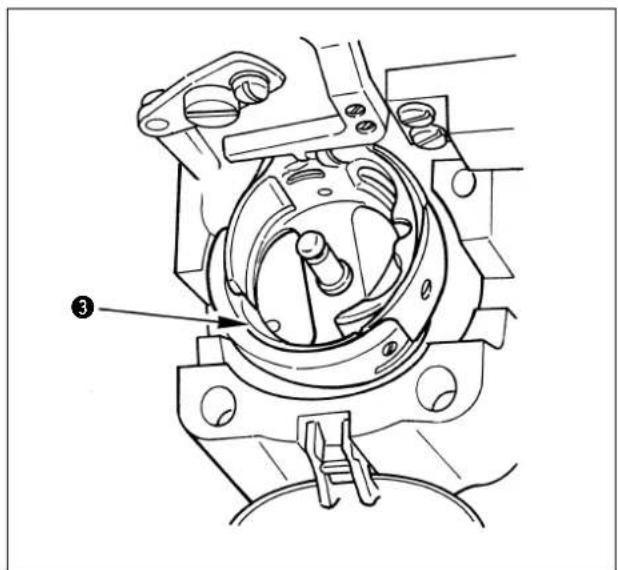
2) Apply one drop of oil to hook race ③ part to spread on it.
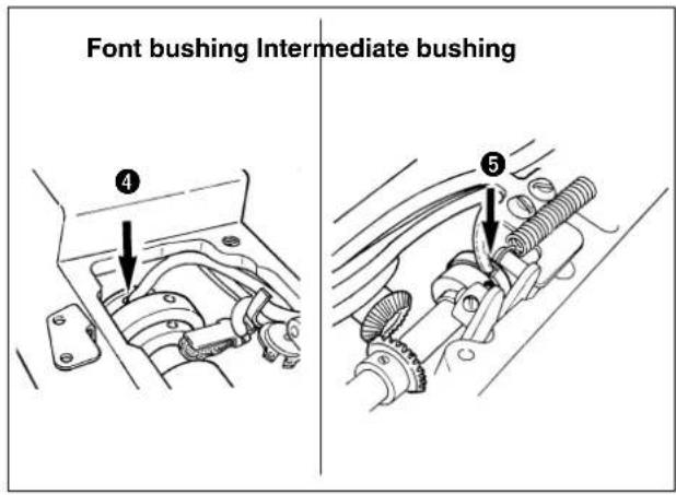
3) Remove the top cover, and apply oil to front bushing ④ and intermediate bushing ⑤.

Be sure to perform the above 2) and 3) steps when the machine is first installed, or when it is run after a long period of disuse.
2. Attaching the needle

WARNING :
Turn OFF the power before starting the work so as to prevent accidents caused by abrupt start of the sewing machine.
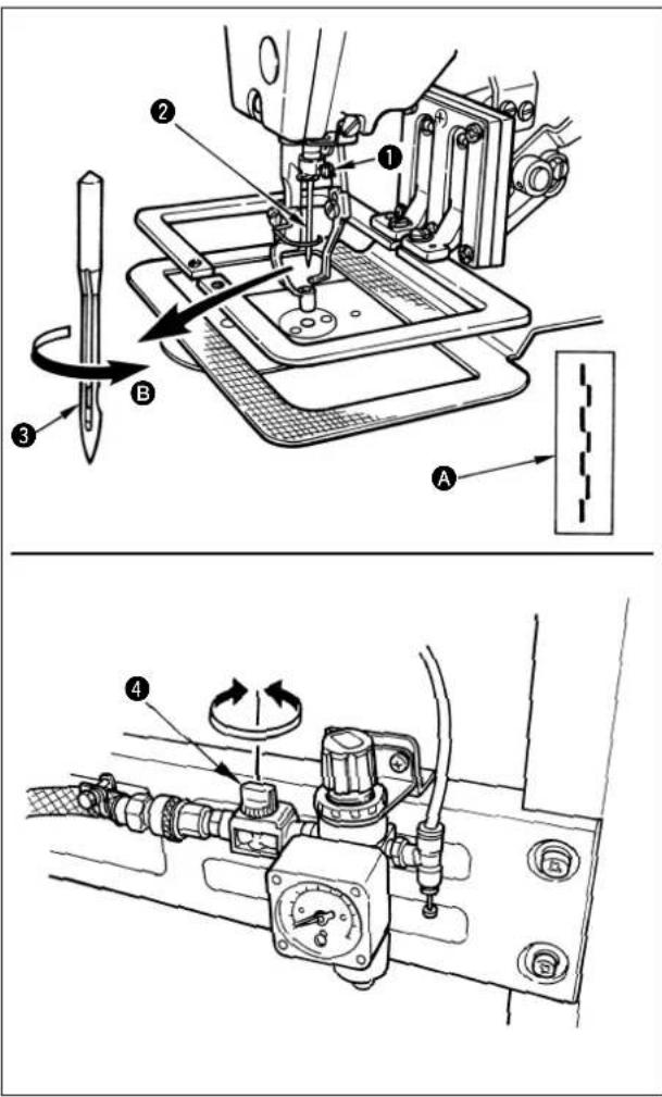
Loosen setscrew ① and hold needle ② with the long groove facing toward you. Then fully insert it into the hole in the needle bar, and tighten setscrew ①.

-
If the stitches are made as shown in Ⓐ, attach the needle facing to the direction Ⓑ to a small extent.
-
If the wiper interferes with the needle, turn the hand pulley and slightly lower the needle bar, or turn the air cock ④ of the filter regulator and expel the air.

When using the needle other than the one supplied at the time of delivery, it may be necessary to replace the hook. See the table of the gauge parts on P62.
3. Threading the machine head

WARNING :
Do not place your fingers or any thing under the presser since there is a danger of damage of your fingers or hands caused by being caught in the presser, needle, etc.
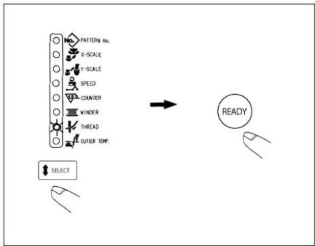
When threading through the needle, perform following operation to lower the intermediate presser and the feeding frame.
1) Press key on the operation box to light up the threading LED.
2) Press key and the intermediate presser and the feeding frame come down.
3) After threading through the needle, press again key, and the intermediate presser and the feeding frame return to their home positions.
Pull out the thread by approximately 4 cm from the needle after threading through the needle.
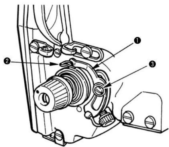
4. Installing and removing the bobbin case

WARNING :
Turn OFF the power before starting the work so as to prevent accidents caused by abrupt start of the sewing machine.
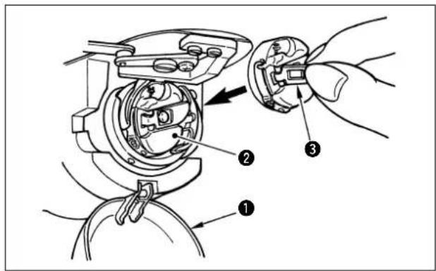
1) Open hook cover ①.
2) Raise latch ③ of bobbin case ②, and remove the bobbin case.
3) When installing the bobbin case, fully insert it into the shuttle shaft, and close the latch.

If it is not fully inserted, bobbin case ② may slip off during sewing.
5. Installing the bobbin
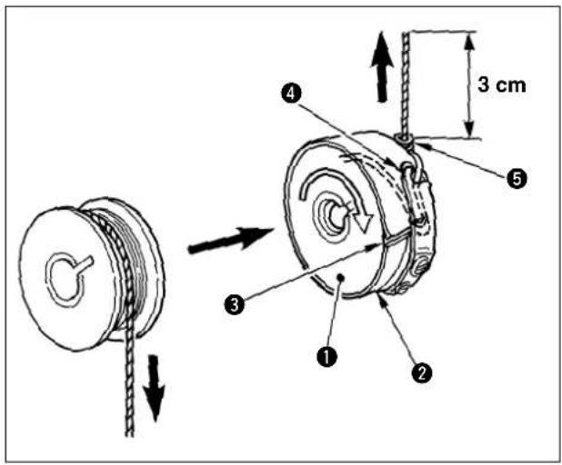
1) Set the bobbin ① into bobbin case ② in the direction shown in the figure.
2) Pass the thread through thread slit ③ of bobbin case ②, and pull the thread as it is. By so doing, the thread will pass under the tension spring and be pulled out from thread hole ④.
3) Pass the thread through bobbin thread guide ⑤, and pull out the thread by 3 cm from the bobbin thread guide.

If the bobbin is installed in the bobbin case orienting the reverse direction, the bobbin thread pulling out will result in an inconsistent state.
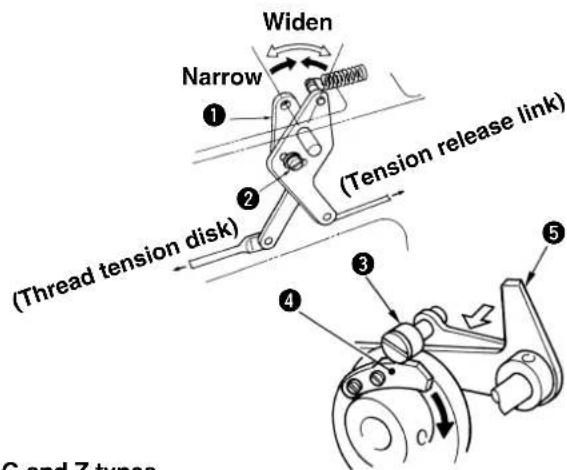
6. Adjusting the thread tension
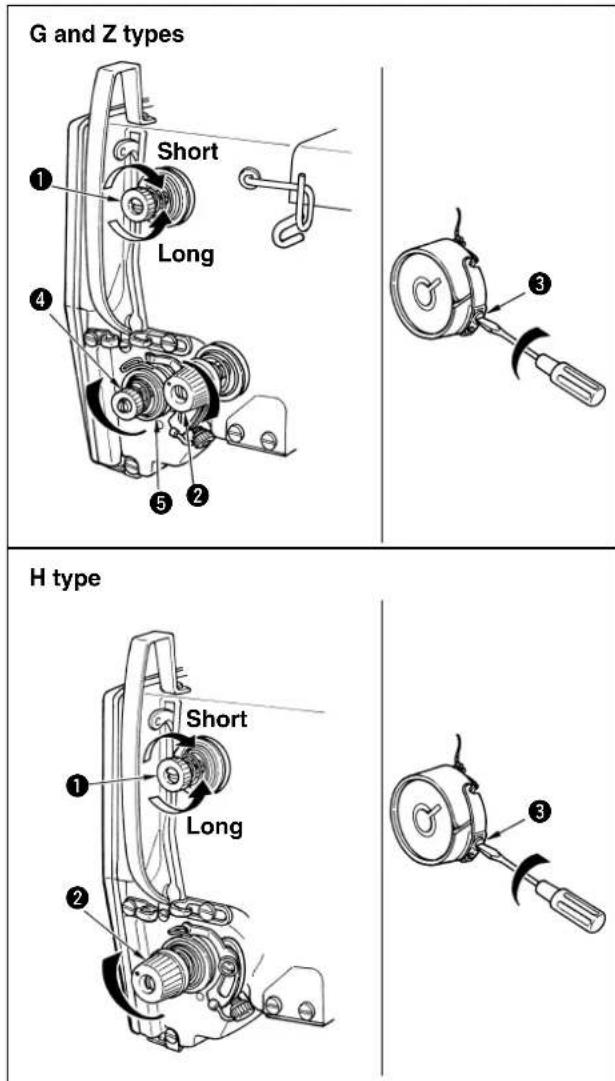
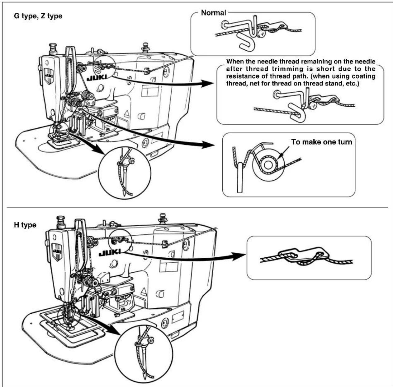
If thread tension controller No. 1 ① is turned clockwise, the length of remaining thread on the needle after thread trimming will be shorter. If it is turned counterclockwise, the length will be longer.
Shorten the length to such an extent that the thread is not slipped off.
Adjust the needle thread tension with thread tension controller No. 2 ②, and bobbin thread with ③.
It is not necessary to normally adjust auxiliary thread tension ④ attached to G and Z types. However, turn it counterclockwise to decrease the thread tension when needle thread slips out of thread guide wheel ⑤ and the thread guide wheel does not stably turn.
7. Adjusting the thread take-up spring
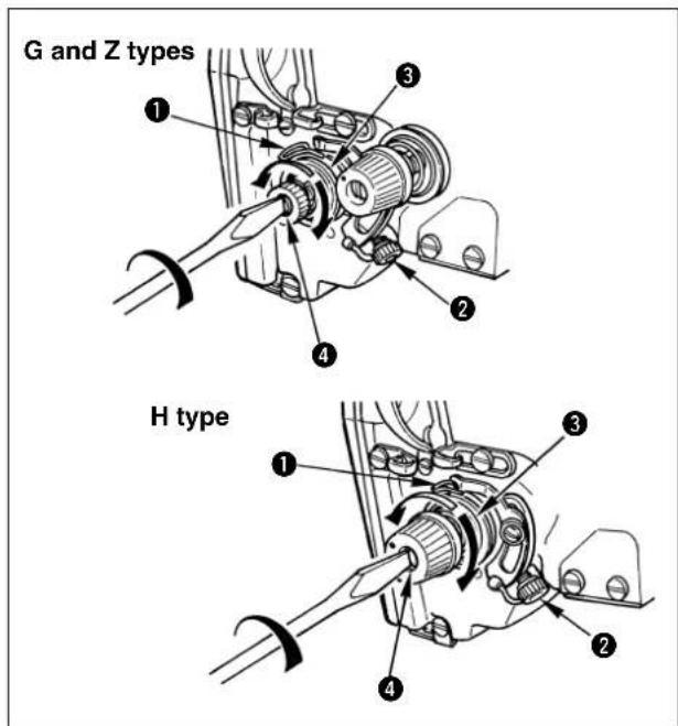
The standard stroke of thread take-up spring ① is 6 to 8 mm, and adjust the tension in accordance with needle thread tension.
1) Adjusting the stroke Loosen setscrew ②, and turn the whole of thread tension ③.
2) Adjusting the pressure Insert a screwdriver into the slit of thread tension rod ④ and turn it while setscrew ② is held tightened.
3) When the stroke of thread take-up spring is changed, adjust the thread breakage detector plate referring to Page 43.
8. Adjusting the height of the intermediate presser (for LK-1942 only)
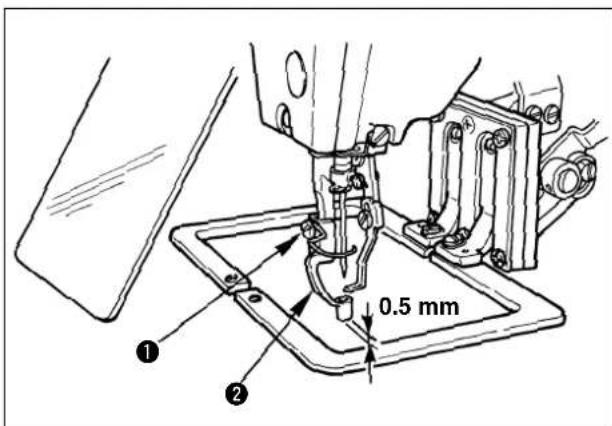
1) Lower the intermediate presser ②. (Refer to "3. Threading the machine head".)
2) Turn the handwheel to lower intermediate presser ② to its lowest position.
3) Loosen setscrew ① and adjust the height of intermediate presser ② so that the clearance provided between the intermediate presser and the cloth is approximately 0.5 mm.
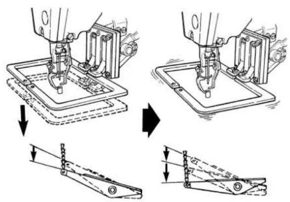
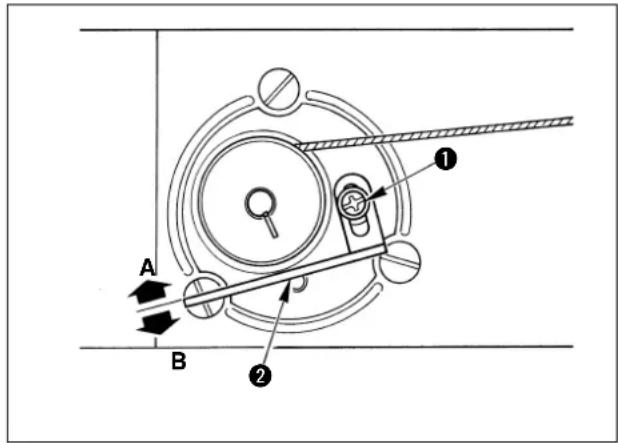
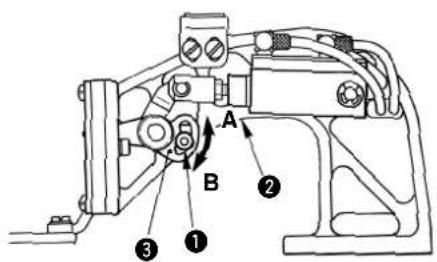
9. Adjusting the intermediate presser stroke (for LK-1942 only)
9-1. Adjusting the intermediate presser stroke to 4 to 10 mm
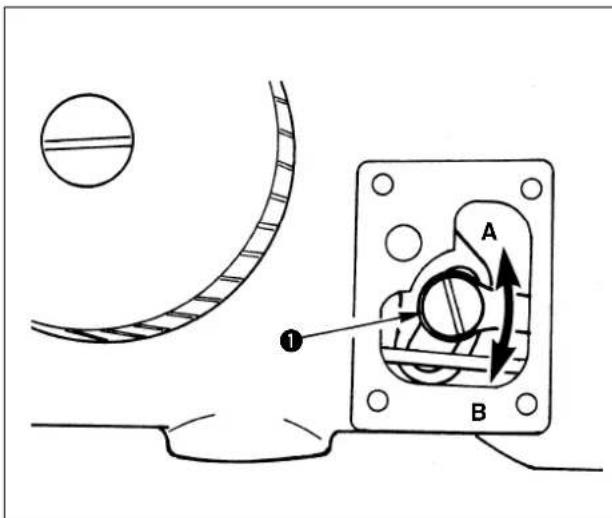
1) Remove the machine arm side cover.
2) Loosen setscrew ① and move it in the direction of arrow for adjustment.
3) If moving in the direction of A, the stroke will be decreased. (Min. 4 mm)
If moving in the direction of B, the stroke will be increased. (Max. 10 mm)

The nut may be removed if setscrew ① is excessively loosened. So, be careful. Loosen setscrew ① by a half turn to properly adjust the stroke.
9-2. Adjusting the intermediate presser stroke to 0 mm
1) Set the intermediate presser stroke to the minimum (4 mm). (See 9-1, p.23.)
2) Remove the face plate.
3) Remove setscrew ①, invert intermediate presser stopper ②, and attach it again with setscrew ①.
natural_image
Technical line drawing of a mechanical assembly with no visible text or symbolsV. OPERATION OF THE SEWING MACHINE (BASIC)
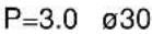
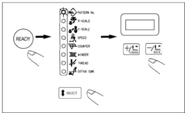
1. Item data setting
Set each item following the procedure described below.

Switch design on the control box may be different from each other in accordance with the models.
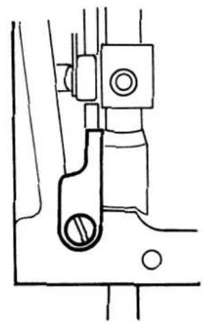
flowchart
graph LR
    A["Setting of the pattern No."] --> B["Setting of the X scale"]
    B --> C["Setting of the Y scale"]
    C --> D["Setting of the max. sewing speed limitation"]
    D --> E["Setting of the heat cutter temperature (For Z type only)"]
(1) Turn ON the power switch
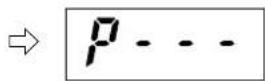
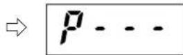
Pattern No. of the item selection lights up, and the pattern No. is indicated on the data display.
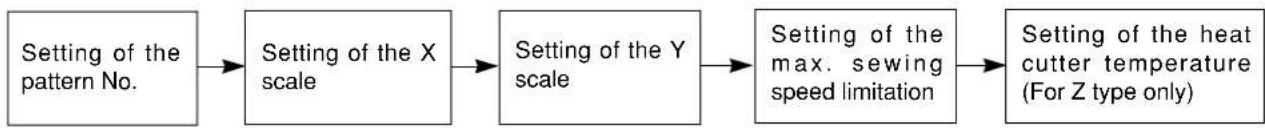
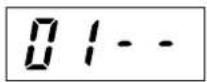
(2) Setting of the pattern No.
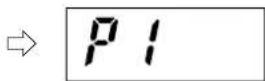
1) Press the key to indicate the item "Pattern NO".
2) Press the or L+ key to indicate Pattern No.
1 to 99 on the display.
In case the pattern is not prepared, indicate the service pattern No. 51 to 53 inputted beforehand at the time of delivery. For LK-1941, the intermediate presser is not provided. Prepare the presser in accordance with the sewing pattern.
| Service pattern No. | Shape | |
 | 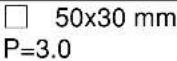 |  |
 |  |  |
 |  |  |
 |  |  |
 | Sewing cannot be performed since this No. is for the pattern for adjusting the amount of oil in the hook. (See P. 45.) | |
(3) Setting of the scale
Setting of the X scale
1) Press the Key to indicate the item "X Scale".
2) Press the +/-L or -key to set the scale in the range of 20% to 200%.
Setting of the Y scale
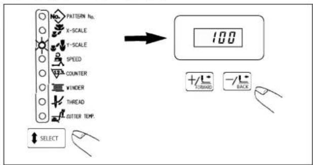
1) Press the Key to indicate the item "Y Scale".
2) Press the of key to set the scale in the range of 20% to 200%.

Enlargement/reduction is a mode of enlargement/reduction of stitch length. When enlargement/reduction is performed, the number of stitches is fixed and the stitch length varies.
(4) Setting of the max. sewing speed limitation

1) Press the key to indicate the item "Speed".
2) Press the orl-key to indicate " " on 400
the display. (Setting of 400 sti/min)
(5) Setting of the heat cutter temperature (For Z type only)
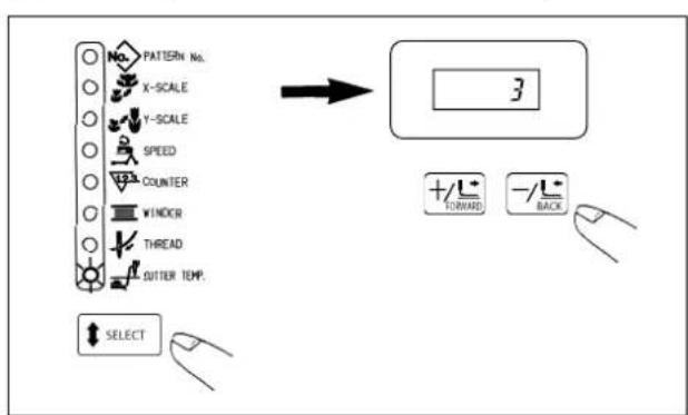
1) Press the key to indicate the item "Cutter TEMP.".
2) Press the +of- key to indicate the item "3" on the display. (Setting of level 3)

- Hot wire plate is a consumable part. - Level “3” of the heat cutter temperature is the standard set value. The higher the level is raised, the more the thread trimming performance is improved. However, when the level is raised more than necessary, damage or deterioration of the service life of the hot wire plate may occur. When thread trimming failure occurs at the standard setting value, perform the proper action referring to “X-5. Troubles and corrective measures (sewing conditions)”.
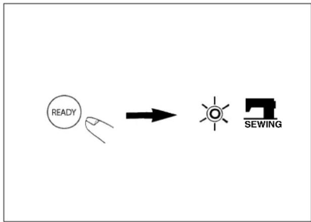
(6) Finish of setting
flowchart
graph LR
    A["READY"] --> B[" Sunset Icon"]
    B --> C["SEWING"]
1) Press the key.
2) The feeding frame comes down and moves. Then, after it has been raised, the sewing LED lights up, and the sewing is ready.
※ If the SELECT key is pressed, you can make sure the set value of the respective items again.

Use after checking the pattern No. Press the sewing ready switch while No. other than the service pattern is indicated on the display, and the error No. E-1 will be shown. At this time, set again the pattern No. which has been registered.
2. Checking the contour of a sewing pattern

WARNING :
- Make sure without fail of the contour of the sewing pattern after selection of the sewing pattern.
If the sewing pattern extends outside the work clamp feet, the needle will interfere with the work clamp feet during sewing, causing dangerous troubles including needle breakage. - When checking the sewing pattern, do not depress the pedal switch up to the second step.
Sewing starts if the pedal switch is depressed up the second step.
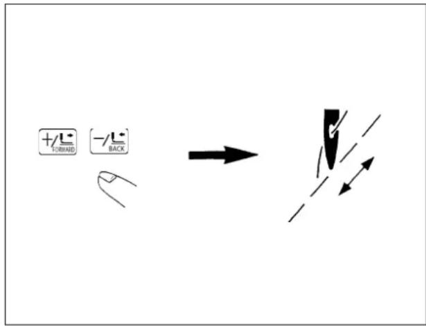
1) Depress the pedal switch to the first step to descend the feeding frame.
2) Every press on the ☐ or ☐ key, the ☐ feeding frame will move by one stitch. Keeping the key held pressed, the feeding frame will move continuously.
3) If the key is pressed, the needle point will return to the starting position, and the feeding frame will go up.

If the feed is fed by one stitch, detach your foot from the pedal.
3. Sewing
For without AW device
1-pedal type
1-pedal type
1) Set a workpiece on the feeding frame section.
2) Depress the pedal switch up to the first step, and the feeding frame will come down. If you detach your foot from the pedal switch, the feeding frame will go up.
3) Depress the pedal switch up to the second step after lowering the feeding frame, and the sewing machine will start the sewing.
4) After the sewing machine completes the sewing, the feeding frame will return to the home place, and go up.
For with AW device
When 2-step PK pedal is used
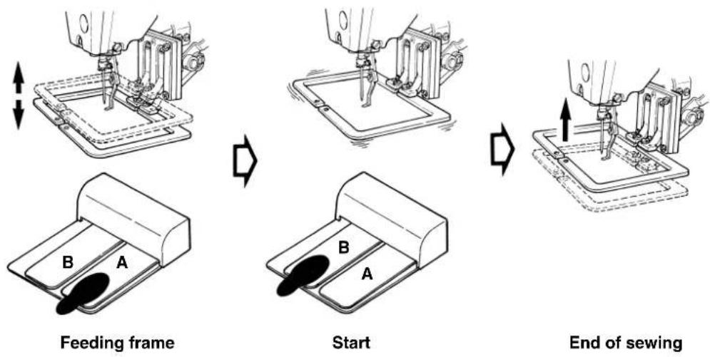
2-step PK pedal
1) Set a workpiece on the feeding frame section.
2) Depress the pedal A, the feeding frame will come down. If depressing the pedal again, the feeding frame will go up.
3) Depress the pedal B, and the sewing machine will start sewing.
4) After the sewing machine completes the sewing, the feeding frame will return to the home place, and go up.

In case of the Z type, the feeding frame performs the movement which is not commanded by the pattern data when trimming thread. However, it is not abnormal.
4. CHANGE TO THE OTHER SEWING PATTERN
flowchart
graph TD
    A["READY"] --> B["PATTERN No."]
    B --> C["X-SCALE"]
    B --> D["Y-SCALE"]
    B --> E["SPEED"]
    B --> F["COUNTER"]
    B --> G["WINDER"]
    B --> H["THREAD"]
    B --> I["CUTTER TEMP."]
    J["+/-/− FORNING"] --> K["BACK"]
    L["SELECT"] --> M["Hand icon"]
1) Press the key. (The sewing LED will go off.)
2) Press the to indicate the item "Pattern No.".
3) Set the items of 1-(2) to (5). For further steps, return to the steps of "2. Checking the contour of a sewing pattern".
5. Temporarily stopping the sewing machine
You can temporarily stop the sewing machine during sewing or sewing pattern shape checking procedure.
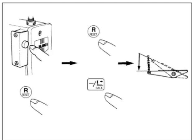
5-1 How to temporarily stop the sewing machine
Press temporary stop switch ① while the sewing machine is running.
The sewing machine stops, and "E5" will be indicated on the operation box.
5-2. Re-starting (re-sewing)

WARNING :
The sewing machine makes a revolution and the needle goes up and comes down. So, never place your fingers or any other thing under the needle.
flowchart
graph TD
    A["Switch"] --> B["R RESET"]
    B --> C["-L-Back"]
    C --> D["Switch"]
    style A fill:#f9f,stroke:#333
    style B fill:#ccf,stroke:#333
    style C fill:#cfc,stroke:#333
    style D fill:#fcc,stroke:#333
1) Press the temporary stop switch twice or press key to make the thread trimming.
( It is not necessary to do so when the needle thread is not tied with the cloth such as jump feed or the like, or continuing the sewing as it is.)
2) Press key to return the needle point to the starting position or desired position.
( It is not necessary to do so when re-starting the sewing from the same position.)
3) Re-starting can be made by depressing the pedal switch.
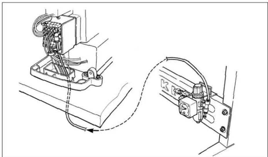
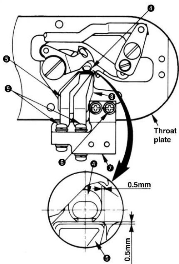
6. Winding the bobbin thread
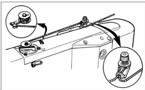
6-1. To wind a bobbin while the sewing machine is performing sewing
natural_image
Technical diagram of a mechanical assembly with two circular insets showing close-up views of components (no text or symbols)Thread the bobbin winder and wind the thread onto the bobbin as illustrated in the figure.
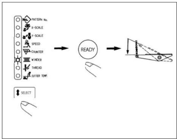
6-2. To wind a bobbin independently

WARNING :
While the bobbin winder winds a bobbin, the feeding frame does not move but the needle bar moves, So, do not place your fingers or any obstacle under the needle.
flowchart
graph LR
    A["PATTERN No."] --> B["READY"]
    C["X-SCALE"] --> B
    D["Y-SCALE"] --> B
    E["SPEED"] --> B
    F["COUNTER"] --> B
    G["VINDER"] --> B
    H["THREAD"] --> B
    I["OUTPER TEM."] --> B
    J["SELECT"] --> B
1) Press the key to select the item "Bobbin winder".

If the "Sewing LED" is lit up, the selection cannot be made.
2) Press the ⏻key, and the feeding frame come down.

Immediately after the power is ON, READY key is not valid. Press REkey after setting the pattern once.
3) Depress the start switch, and the bobbin winder will start to wind the bobbin.
4) Press the temporary stop switch, depress again the start switch, or press any one of the switches on the operation box, and the bobbin winder will stop.
5) Press the key to release it.
6-3. Adjustment of the bobbin thread winder components

WARNING :
Turn OFF the power before starting the work so as to prevent accidents caused by abrupt start of the sewing machine.
(1) Adjusting the bobbin winder thread tension
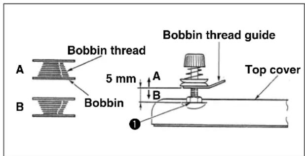
1) Loosen nut ①, and adjust the height so that the clearance between the bobbin thread guide and the top cover should be approximately 5 mm.
2) If the bobbin thread is wound like A, the height should be higher than 5 mm. If it is like B, the height should be lower than 5 mm.
(2) Adjusting the winding amount of the bobbin thread
1) If the winding amount of the bobbin thread is excessive, loosen setscrew ①, and move bobbin thread winder lever ② in the direction A. Then fix it.
2) If the winding amount of the bobbin thread is small, loosen setscrew①, and move bobbin thread winder lever ② in the direction B. Then fix it.
7. Cautions in operation
Reference for the sewing speed to be applied
| Sewing speed (sti/min) | |
| Denim 8 pcs. 2,000 to 2,200 | |
| Denim 12 pcs. 1,500 to 1,800 | |
| Synthetic leather 1,500 to 1,800 | |
| Leather 1,500 to 1,800 | |
| Seat belt 1,000 to 1,200 | |
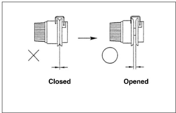
(1) When threading and the sewing machine is switched ON, in case the thread tension disk is closed, sew the desired sewing pattern. After thread trimming, the thread tension disk will open.
(2) When the error indicator lamp lights up, be sure to check the cause of trouble and take a proper corrective measure.
(3) Do not draw, by hand, the material being sewn during sewing. Doing so will cause the needle shift from the correct position. If the needle moves from the correct position, press the key two times. This will return the needle to the normal origin.
※ To prevent the thread breakage due to the needle heat, set the sewing speed referring to the left-hand table in accordance with the sewing conditions.
VI. OPERATION OF THE SEWING MACHINE (ADVANCED)
1. Performing sewing using the pattern keys (P1, P2 and P3 keys)
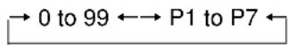
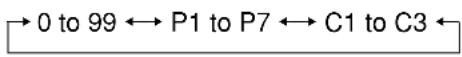
If the patterns (No. 1 to 99) which have been already registered are registered in P1 to P7, the pattern calling can be made by one-touch without performing the selection by the pattern No. scrolling.
※ When selecting P4, P5, P6 or P7, the selection can be made by the combination of ^P1 to ^P3 keys.
P1 : Press the P1 key. P4 : Simultaneously press the P1 and P2 keys.
P2 : Press the 2 key. P5 : Simultaneously press the 1 and 3 keys.
P3 : Press the 3 key. P6 : Simultaneously press the 2 and 3 keys.
P7 : Simultaneously press the 1 , 2 and 3 keys.
(1) Registration to the pattern key
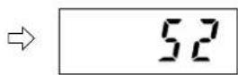
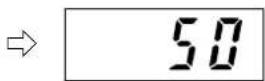
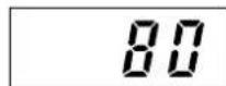
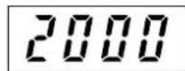
Setting example : Register following setting to the P1.
Pattern No. 52
X Scale rate : 50%
Y Scale rate : 80%
Max. sewing speed limitation : 2,000 sti/min.
1) Pressing the key, turn ON the power switch.
2) Press the P1 key.
3) Press the Key to indicate the Pattern No. Set the pattern No. to Pattern No. "5" using the or+/key. -/L-BACK
4) Performing the same operation as that in the step 3), set X Scale rate to "50%", Y Scale rate to "80%" and Max. sewing speed limitation to "2,000 sti/min".
5) Press the key to finalize the registration.
※ If you desire to register in P2 to P7, press the ^P2 to ^P7 keys at the step 2), and perform the steps 3) to 5).
6) When the registration has been completed, turn OFF the power switch, and again turn ON the power switch. Then, the sewing machine can be used as usual.
(2) Sewing operation
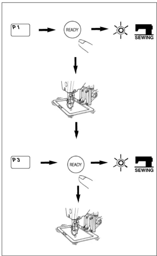
Operation example : After performing sewing with the contents of the registered P1, perform sewing with the contents of P3.
flowchart
graph TD
    A["P 1"] --> B["READY"]
    B --> C["SEWING"]
    B --> D["↓"]
    D --> E["Machine with sewing machine"]
    E --> F["↓"]
    F --> G["READY"]
    G --> H["SEWING"]
    G --> I["↓"]
    I --> J["Machine with sewing machine"]
    J --> K["↓"]
    K --> L["P 3"]
1) Turn ON the power switch.
2) Press the 1 key.
3) Press the key, and when the sewing LED lights up, the work clamp foot goes up after it has moved.
4) Check the contour of the sewing pattern.
(Refer to the item "Checking the contour of a sewing pattern".)
5) If the contour of the sewing pattern is acceptable, the sewing can be made.
6) After the completion of sewing, press the 3 key. Then the work clamp foot will move to the sewing start point after the origin retrieval. (The P keys can operate the pattern chage by one-touch even when the sewing LED is lighting up.)
7) Perform the above items 4) and 5).
※ The P1 to P7 can be indicated on the display when selecting the pattern by pressing the ☐☐☐ ☐☐☐ ☐☐☐ ☐☐☐ ☐☐☐ ☐☐☐ ☐☐☐ ☐☐☐ ☐☐☐ ☐☐☐ ☐☐☐ ☐☐☐ ☐☐☐ ☐☐☐ ☐☐☐ ☐☐☐ ☐☐☐ ☐☐☐ ☐☐☐ ☐☐☐ ☐☐☐ ☐☐☐ ☐☐☐ ☐☐☐ ☐☐☐ ☐☐☑ ☐☐☑ ☐☐☑ ☐☐☑ ☐☐☑ ☐☐☑ ☐☐☑ ☐☐☑ ☐☐☑ ☐☐☑ ☐☐☑ ☐☐☑ ☐☐☑ ☐☐☑ ☐☐☑ ☐☐☑ ☐☐☑ ☐☐☑ ☐☐☑ ☐☐☑ ☐☐☑ ☐☐☑ ☐☐☑ ☐☐☑ ☐☐☑ ☐☐□
P1 to P7 which have not been registered are not indicated.
2. Performing sewing using the combination function
By arranging in the order of use of the pattern keys (P1 to P7) which have been already registered and registering in the C1, C2 and C3, the sewing pattern will change in the order every time the sewing machine finishes the sewing.
※ The maximum 15 pattern combinations of P1 to P7 can be registered in the C1, C2 or C3.
(1) Registration of the combination
Setting example : Combine in the order of P1, P2, P3, and register them in the C1.
1) Pressing the P1 and keys, turn ON the power switch.
→ [1…
2) Press the Key. Then press the P1 key.
1-P1
3) Press the Key. Then press the P2 key.
2-92
4) Press the Key. Then press the P3 key.
3-P3
5) Press the key to finalize the registration.
[1]
6) Turn OFF the power switch, and again turn ON the power switch. The sewing machine can be used as usual.
※ 1. At the operation of the step 1), if the power switch is ON, pressing the P2 or P3 key and the ↑ SELECT key, in case of the P2 key, the registration can be made in the C2. In case of the P3 key, the registration can be made in the C3.
※ 2. Simultaneously press the P1 to P3 keys to set the P4 to P7.
※ 3. 10 to 15 showing the order will be indicated A to F.

The sewing patterns which have not been registered in the pattern keys (P1 to P7) can not be combined.
(2) Sewing operation
Operation example : Perform sewing with the contents of the registered C1.
flowchart
graph TD
    A["Pattern No. X-SCALE Y-SCALE SPEED COUNTER WINDER THREAD CUTTER TEMP."] --> B["1-1"]
    B --> C["READY"]
    C --> D["SEWING"]
    E["FORWARD BACK"] --> F["1-1"]
    F --> G["1-2"]
    G --> H["1-F"]
    H --> I["1-F"]
    I --> J["1-1"]
    J --> K["1-2"]
    K --> L["+/- FORWARD -/+ BACK"]
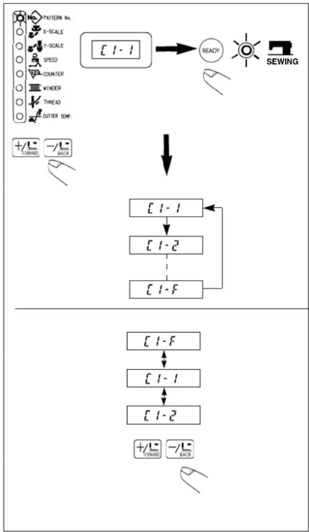
1) Turn ON the power switch.
2) Set the pattern No. to "using the or

Scroll as follows :

※ P1 to P7 and C1 to C3 which have not been registered are not indicated.
3) Press the key. When the sewing LED lights up, the feeding frame will go up after having moved.
4) If the contour of the pattern is acceptable, the sewing can be made.
5) Every time the sewing is finished, the step is made according to the combination. After completing one cycle of sewing, the step returns to the first step. The sewing can be made repeatedly.
※ 1. When you desire to return the pattern to the previous one or step to the next one during sewing, press the -ot key in a state that the sewing LED lights up.
The indication of the pattern No. will change, and the feeding frame will move to the sewing start point.
※ 2. If the contents of P1 to P7 are changed after registration of C1 to C3, the contents of P1 to P7 used in C1 to C3 will change. So, be careful.
※ 3. Make sure of the contour of the pattern for each of the patterns.
(Refer to the item "V-2. Checking the contour of a sewing pattern".)
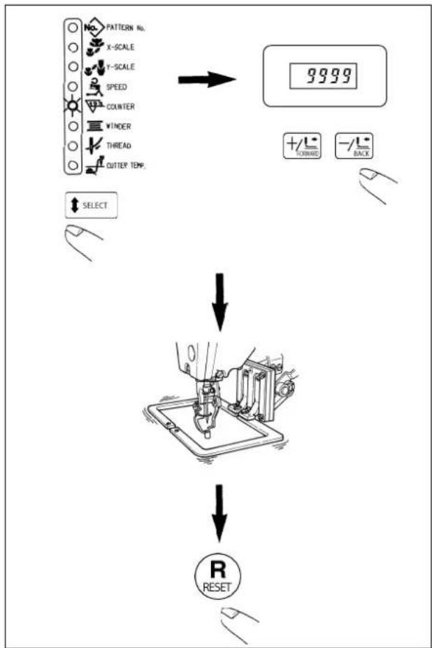
3. Performing sewing using the "bobbin thread counter"
The production counter can be used as the bobbin thread counter. In case a same sewing pattern is sewn in repetition, the sewing machine will stop sewing when the number of times (the specified number) that can be sewn with a bobbin is reached. The bobbin thread counter is of the subtracting method.

The counter at the time of delivery is set to the production counter (adding method). If it is used as the bobbin thread counter, it is necessary to change the memory switch. AW-2 type cannot function.
(Refer to the item "VIII. HOW TO USE THE MEMORY SWITCH".)
flowchart
graph TD
    A["PATTERN NO.<br>X-SCALE<br>Y-SCALE<br>SPEED<br>COUNTER<br>VINDER<br>THREAD<br>CUTTER TEMP."] --> B["9999"]
    B --> C["+/-/COINAR +/-/BACK"]
    D["SELECT"] --> E["↓"]
    E --> F["↓"]
    F --> G["R RESET"]
1) While the sewing LED goes off, press the key to indicate the "Counter".
2) Then press the + key/and set the specified number of times that can be sewn with a bobbin.
3) Every time the sewing machine finishes a sewing cycle, counting-down is made by one.
4) When the sewing machine finishes the specified number of times, the sewing machine does not start even if depressing the pedal.
5) Replace the bobbin with a new one, and press the R key.
6) Repeat the steps of procedure from the steps 3) to 5).
4. How to take out the sewing products when the thread cutting failure has occurred (for Z type only)
Thread is cut and the sewing product can be taken out by reheating the hot wire plate when needle thread or bobbin thread is not cut at the time of completion of sewing.

Thread is not cut even when the hot wire plate is reheated according to the cause of thread cutting failure.
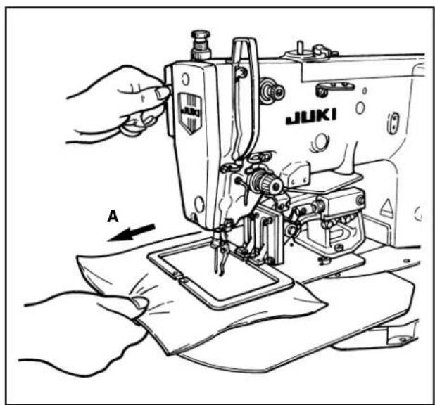
1) Pull the sewing product in the direction of A and take the slack of the thread in the state of completion of sewing (state that the sewing LED is lit up and the feeding frame is raised).
2) When the temporary stop switch is pressed, the hot wire plate is heated and the thread is cut.

Once the operation is performed, re-operation cannot be performed for five seconds.
VII. MAINTENANCE
1. Adjusting the height of the needle bar

WARNING :
Turn OFF the power before starting the work so as to prevent accidents caused by abrupt start of the sewing machine.
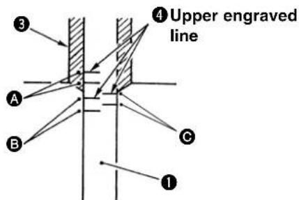
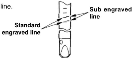
A : Engraved line for DP x 5
B : Engraved line for DP x 17 #18 to #25
© : Engraved line for DP x 17 #26
Bring needle bar ① to the lowest position of its stroke. Loosen needle bar connection screw ② and adjust so that upper marker line ④ engraved on the needle bar aligns with the bottom end of needle bar bushing, lower ③.

After the adjustment, make sure that there is no uneven torque.
※ When stitch skipping occurs in accordance with the sewing conditions, adjust the height of the needle bar so as to lower it by 0.5 to 1 mm from the needle bar engraved line ④.
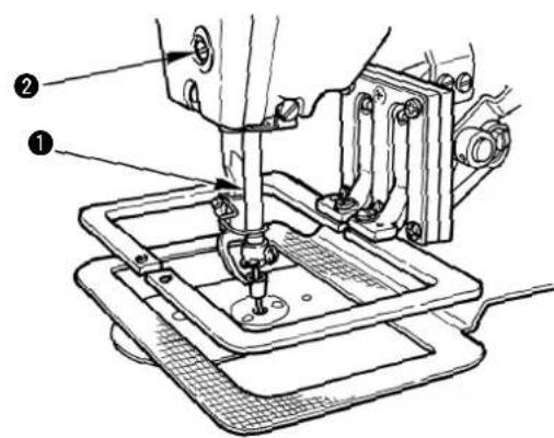
2. Adjusting the needle-to-shuttle relation

WARNING :
Turn OFF the power before starting the work so as to prevent accidents caused by abrupt start of the sewing machine.
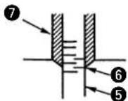
2) Remove setscrew ① and remove inner hook stopper ②. Further, loosen right and left setscrews ③ and remove oil shield plate ④.
At this time, do not try to forcibly remove the oil shield plate. Turn the handwheel and remove it at the position near to the up-stop position of the handwheel.
Relation between needle and engraved lines
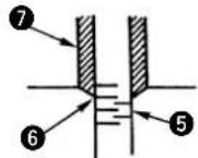
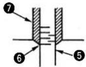
When DPx5 is used.
When DPx17 #18 to #25 is used.
When DPx17 #26 is used.
1) Turn the handwheel by hand in the direction of normal rotation. When needle bar ⑤ has gone up, adjust so that lower marker line ⑥ engraved on the needle bar aligns with the bottom end of the needle bar bushing ⑦, lower.

Turn the needle guard section of the inner hook to the lower side so that the inner hook does not come in contact with the needle.
natural_image
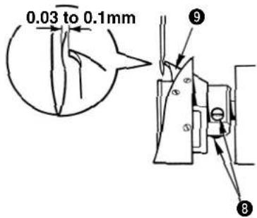
Technical diagram showing mechanical assembly with arrows indicating motion, no readable text or symbols present3) Loosen setscrew 8 and move the hook to adjust so that the blade point of the hook is aligned with the center of the needle.
Adjusting the clearance provided between the needle and the hook (Perform this adjustment together with the aforementioned adjustment.)
Installing the inner hook stopper
Groove on throat plate
Groove on inner hook
Turn the handwheel and loosen setscrew ⑧ to adjust so that the clearance of 0.03 to 0.1 mm is provided between the needle and blade point ⑨ of the hook when the blade point of the hook is aligned with the center of the needle.
1) Fit the projection at the top end of inner hook stopper ① to the groove on the inner hook, and install setscrews ②.
2) There is a slight play between inner hook stopper ① and setscrews ② in the direction of arrow mark A (lateral direction). Making the projection of inner hook stopper ① come in contact with the groove on the throat plate, fix the inner hook stopper with setscrews ② so that the setscrews are positioned approximately in the center of the play.
Kinds and application of the hook
There are four kinds of hooks for LK-1940 Series. It is necessary to use the hook properly in accordance with the needle size and sewing conditions.
Use a suitable hook referring to "Correspondence table of needle size" and "Correspondence table of sewing conditions" described below.
In addition, the needle sticking (needle stuck into needle thread or needle stuck into bobbin thread) occurs due to the kind of thread or stitching direction. Then "hangnail", "thread breakage", or "stitch skipping", may occur. In this case, such problem can be solved by making the needle tip round as an emergency measure.
However, when replacing the needle with the ball-point one, refer to the table below since the needle guard amount may be changed.
[Correspondence table of needle size]
(Symbols, H, G, and Z in the table denote the combination of the types at the time of delivery.)
ORGAN needle (standard needle point)
| Needle sizeKind of hook | #18 #19 | #20 #21 | #22 #23 | #24 #25 | #26 | |||||
| Lubricating hook A (14436554) | H ○ | ○ | ○ | |||||||
| Lubricating hook B (14436703) | ● | ○ | ○ | ○ | ||||||
| Lubricating hook C (14436307) | ● | ○ | ○ | G ○ | ||||||
| Lubricating hook D (14436158) | ● | ● | ○ | Z Domestic ○ | Z Export ● |
ORGAN needle (ball-point)
| Needle sizeKind of hook | #18 #19 | #20 #21 | #22 #23 | #24 #25 | ||||
| Lubricating hook A (14436554) | ○ | ○ | ○ | |||||
| Lubricating hook B (14436703)Lubricating hook C (14436307) | ● | ○ | ○ | ○ | ||||
| Lubricating hook D (14436158) | ● | ● | ○ | ○ |
SCHMETZ needle (standard needle point)
| Needle sizeKind of hook | #110 (18) | #120( 19) | #125 (20) # | 130 (21) #1 | 40 (22) #1 | 60 (23) #18 | 80 (24) #20 | 00 (25) |
| Lubricating hook A (14436554) | ○ | ○ | ○ | ○ | ○ | ○ | ||
| Lubricating hook B (14436703)Lubricating hook C (14436307) | ● | ● | ● | ○ | ||||
| Lubricating hook D (14436158) | ● |
○ : Perform the hook adjustment with the standard engraved line.
● : Perform the hook adjustment with the sub engraved line.
[Correspondence table of the sewing conditions]
| Feature of hook | Sewing conditions | |
| Lubrication hook A (14436554)Lubrication hook B (14436703) | Thread path presser is long. | When balloon stitches frequently occur due to violent movement of thread at the time of passing the hook in case of thin thread or cotton thread. |
| Lubrication hook C (14436307)Lubrication hook D (14436158) | Thread path presser is short. | When thick thread is used and thread tightness is required. |
![JUKI LK-1941 - [Correspondence table of needle size] - 2](/content/2026/04/638765/images/4cd0c192a9356d9f6345e4cb71c31944fa408c2f9e2c221ca002b930d49aca93.jpg)
The combination of the different kinds of outer and inner hooks can be used under the special sewing conditions.
(Example) Baloon stitch occurs when the lubricating hook D is used under the conditions of ORGAN needle #24 + (plus) cotton thread -> Use the outer hook only of lubricating hook A or B.
3. Adjusting the height of the feeding frame

WARNING :
Turn OFF the power before starting the work so as to prevent accidents caused by abrupt start of the sewing machine.
1) Loosen setscrew ② located in feed bracket ①. Move cloth presser hook ③ in the direction B to increase the height.
2) After adjusting the height, securely tighten setscrews ②.
4. Adjusting the rising amount of the thread tension disk

WARNING :
Turn OFF the power before starting the work so as to prevent accidents caused by abrupt start of the sewing machine.
G and Z types
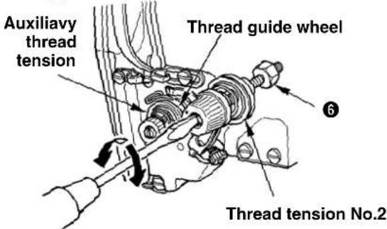
H type
natural_image
Mechanical assembly diagram showing a shaft and housing component (no text or labels)Thread tension No.2
1) Remove the top cover. Make sure that tension release pin ③ rides on tension release notch ④.
2) If the pin does not ride on the notch, push cam follower ⑤ by hand to the direction, and rotate the main shaft in the correct direction to make a state as illustrated in the figure.
3) Under the state as illustrated in the figure, loosen setscrew ② in the tension release adjusting arm. By moving tension release adjusting arm ① to the left or right the rising amount of the thread tension disk will change.
H type : Adjust the rising amount of the thread tension No. 2 to 0.8 to 1.0 mm.
G and Z types : Adjust the rising amount of the auxiliary thread tension so that the thread guide wheel is lightly turned by hand.
4) For the G and Z types, further, adjust the rising amount of the thread tension No. 2. Loosen nut ⑥ and turn clockwise the whole thread tension to increase the amount and counterclockwise to decrease the amount. Adjust the rising amount to 1.0 mm to 1.2 mm.

If the rising amount is insufficient, the length of the remaining thread after thread trimming will be not stable. If the rising amount is excessive, after releasing the rising of the thread tension disk, the disk closing will be defective.
5. The moving knife and counter knife

WARNING :
Turn OFF the power before starting the work so as to prevent accidents caused by abrupt start of the sewing machine.
(1) Position of the moving knife (Common to H, G and hot wire types)
1) Remove the arm cover, and push cam follower ① in the direction of the arrow mark A to enter it into thread trimmer cam ②.
2) Turn hand pulley ③ to rotate the main shaft in the direction of normal rotation and move moving knife ④ to the front end of its travel while cam follower ① is entered into thread trimmer cam ②.
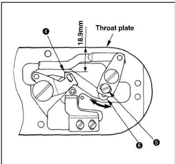
3) Loosen adjustment screw ⑤ and move thread trimming lever (small) ⑥ in the direction of the arrow mark to adjust so that the distance from the left end of the throat plate to the top end of moving knife ④ is 18.9 mm.

In case of the hot wire type, when the aforementioned dimension is larger than specified one, the length of needle thread remaining on the needle after thread trimming may be excessively short.
(2) Position of the counter knife
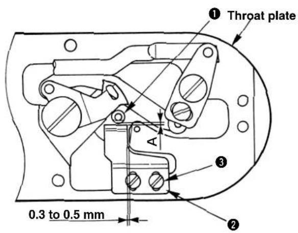
Adsjusting procedure for H type and G type
1) Select dimension A, clearance provided between needle hole guide ① and counter knife ② from the table below in accordance with the type you desire, loosen setscrews ③ and move counter knife ② to djust the position. At this time, provide a clearance of 0.3 to 0.5 mm between the throat plate and counter knife ②.
| H type G type | ||
| Dimension A 0 | 0.8 to 1 mm 1.4 to 1.6 | mm |

If dimension A is small, needle thread or bobbin thread may be too short.
2) Dimension B, difference in height between the counter knife and needle hole guide ① is as shown in the table below. When this dimension is not proper, bend the top end of the counter knife to adjust the dimension.
| H type G type | ||
| Dimension B | 0.25 to 0.35 mm 0.5 to | 0.6 mm |

If dimension B is large, needle thread or bobbin thread may be too short.
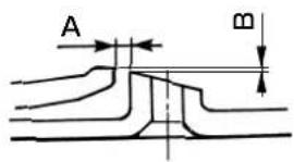
Adjusting procedure for the hot wire type
1) Loosen setscrew ⑥ and move hot wire base ⑦ to adjust so that a clearance of 0.5 mm is provided between needle hole guide ④ and hot wire plate ⑤ both in the longitudinal and lateral directions.
2) Check whether hot wire plate ⑤ and insulation sheet ⑧ come in close contact with each other. If not, loosen setscrews ⑨ and move hot wire plate ⑤ to adjust. (When setscrews ⑨ are loosened, perform again the work of step 1).)
- After adjusting the clearance, check with the tester or the like that there is no electrical continuity in hot wire plate ⑤, needle hole guide ④ and the throat plate. If there is an electrical continuity, temperature will not rise and deterioration of sharpness or cause of trouble will result.
- Adjust the tightening torque of setscrew ⑥ to 98 to 147 N·cm (10 to 15 kgf·cm).
- Adjust the tightening torque of setscrews⑨ to 48 to 98 N·cm (5 to 10 kgf·cm).
6. Thread breakage detector plate

WARNING :
Turn OFF the power before starting the work so as to prevent accidents caused by abrupt start of the sewing machine.
1) Adjust so that thread breakage detector plate ① is always in contact with thread take-up spring ② in the absence of needle thread. (Slack: approx. 0.5 mm)
2) Whenever the stroke of thread take-up spring ② has been changed, be sure to readjust thread breakage detector plate ①. To make this adjustment, loosen screw ③.

Adjust so that thread breakage detector plate ① does not touch any adjacent metallic parts other than thread take-up spring ②.
7. Adjusting the amount of oil in the hook
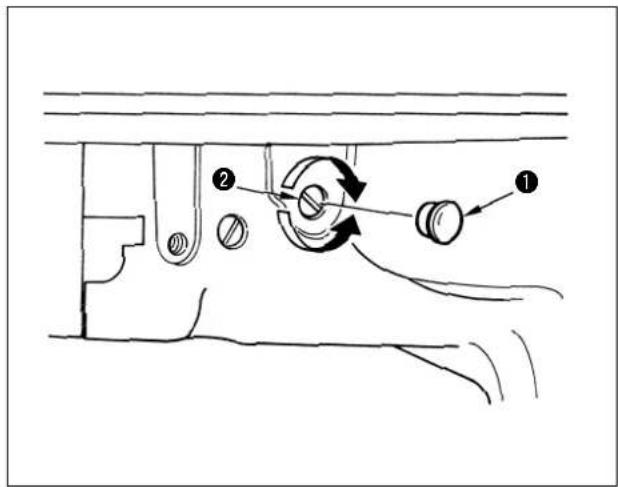
Remove rubber cap ①, turn clockwise adjustment screw ② to decrease the amount of oil in the hook, and counterclockwise to increase the amount of oil in the hook.
Adjust the amount of oil when the followings occur.
a. Decrease the amount of oil in the hook when oil in the oil tank on the machine bed side decreases quickly.
b. Decrease the amount of oil in the hook when oil splashes from the hook are many and oil leaks from the hook cover.
c. Increase the amount of oil in the hook when the hook noise is large.
d. Increase the amount of oil in the hook when pulling up of needle thread is deteriorated due to the shortage of lubrication.
After performing the adjustment, be sure to operate the sewing machine with the pattern No. 60 for checking the amount of oil in the hook to check the amount of oil.
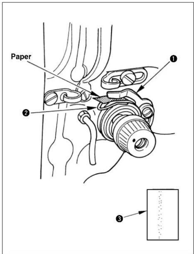
1) Remove oil shield plate. (See p.38.)
2) Remove the needle.
3) Insert a sheet of paper between thread breakage detector plate ① and thread take-up spring ② for insulation.
4) Allow a sheet of paper in approximate 30 mm square to come near the position of approximately 10 mm in the side direction of the hook, and operate the sewing machine with the pattern No. 60. (Set the number of rotations to the maximum one.)
5) After performing operation of one cycle, confirm the amount of oil through the oil mark adhered to the paper③.

The amount of oil in the hook does not change immediately after the adjustment. Be sure to check the amount after operating the sewing machine for approximately 10 minutes.
8. Cleaning the filter

WARNING :
Turn OFF the power before starting the work so as to prevent accidents caused by abrupt start of the sewing machine.
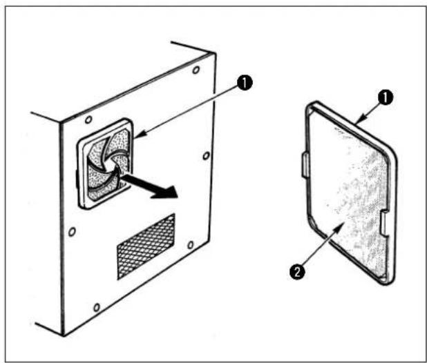
Clean the filter ② of the control box fan once every week.
1) Pull the screen kit ① in the direction of the arrow to remove it.
2) Wash the filter ② under running water.
3) Reinstall the filter ② and the screen kit ①.
9. Draining waste oil

WARNING :
Turn OFF the power before starting the work so as to prevent accidents caused by abrupt start of the sewing machine.
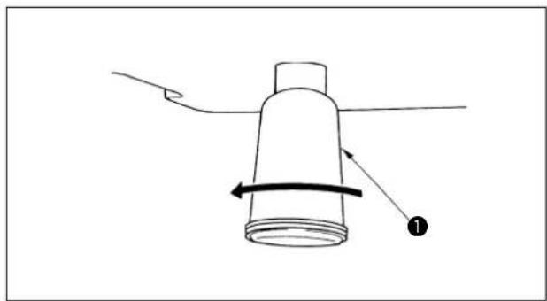
natural_image
Simple line drawing of a cylindrical object with a curved arrow indicating rotation, no text or symbols presentWhen polyethylene oiler ① becomes filled with oil, remove it and drain the oil.
10. Replacing the fuse

WARNING :
To prevent possible accidents caused by electric shock, turn OFF the power, open the control box cover after a lapse of five minutes, and replace the fuse with a new one with the specified capacity.
The machine uses the following five fuses :
①, ②For servo motor power supply protection 10A each (standard melting fuse)
③For solenoid power supply protection 10A (time-lag fuse)
④For stepping motor (X and Y) protection 8A (standard melting fuse)
⑤For 5V power supply protection 3A (standard melting fuse)
VIII. HOW TO USE THE MEMORY SWITCH
1. Starting the memory switch
Pressing Ⓗ key and Ⓗ key, turn ON the power switch. The display gives the indication of the memory switch and the sewing machine operation can be changed.

2. Example of the memory switch setting
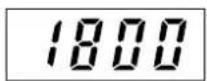
(1) Setting of max. sewing speed limitation
Example of setting : Setting the max. sewing speed limitation to 1,800 sti/min.
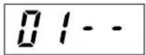
1) After the memory switch has started, press the key to indicate " the display.

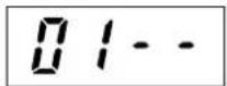
2) Press the key to light up the sewing LED.


3) Indicate "1800" using the key

4) After setting, register using the key.

(2) Setting the soft start speed at the sewing start
The speed of the first stitch to the fifth stitch at the sewing start can be changed in a unit of 100 sti/min.
| State when delivered Setting range | |
| 1st stitch 200 200 to 900 | |
| 2nd stitch 600 200 to 2,200 | |
| 3rd stitch 1,000 200 to 2,200 | |
| 4th stitch 2,200 200 to 2,200 | |
| 5th stitch 2,200 200 to 2,200 |
Unit [sti/min]

For the max. sewing speed, the memory switch NO. 01 (setting the sewing speed limitation) has priority.
Example of setting : The speed is changed as follows :
1st stitch 200 → 400 sti/min, 2nd stitch 600 → 900 sti/min
1) After the memory switch has started, press the key indicate "0" on the display.

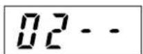
2) Press the key to light up the sewing LED.

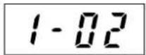
(The 1st stitch, 200 sti/min, will be indicated.)

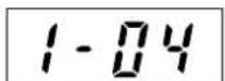
3) Press the key to indicate " . 1 - 04

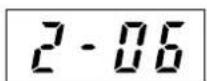
(400 sti/min is set.)

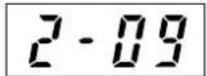
4) Press the Key:

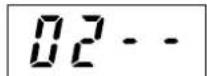
(The 2nd stitch, 600 sti/min will be indicated.)
5) Press the key to indicate “”. 2-09
(900 sti/min is set.)
6) After setting, register using the key.
(3) Setting the counter operation
Example of setting : The production counter (adding method) can be changed to the bobbin thread counter (subtracting counter).
1) After the memory switch has started, press the on the display.
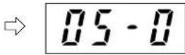
2) Press the key to light up the sewing LED.
3) Press the keV to indicate “”. 05 - 1 Indication on A section 0 : Production counter 1 : Bobbin thread counter
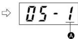
4) After setting, register using the key.
(4) Setting the pedal specifications
This function is set when changing the pedal specification is changed.
Example of setting : the standard 1-pedal specification is changed to the 2-step pedal (optional) specification.
1) After the memory switch has started, press the key indicate "10 on the display.
2) Press the key to light up the sewing LED.
3) Press the key to indicate “”. 10 - 1 Indication on A section
0 : 1-pedal 1 : 2-step pedal, 2-step PK pedal 2 : PK-57 3 : 3-step pedal, 3-step PK pedal (priority to the right) 4 : 3-step pedal, 3-step PK pedal (priority to the left) 5 : 3-step pedal, 3-step PK pedal (no priority)
4) After setting, register using the key.
※ After setting the memory switch, turn OFF the power switch once, and turn ON again. Then, the sewing machine starts running in accordance with the setting made by the memory switches.
3. Table of functions of the memory switch
Note) Contents of the memory switch may vary in accordance with the system ROM revision. (The following contents are in case of "005D".)
| Display Remarks | Function | Setting range | State when delivered | |
 | Setting of the max. sewing speed limitation (in a unit of 100 sti/min) | 200 to 2,200 sti/min | 2,200 sti/min | |
 | Starting speed of 1st to 5th stitch at the sewing start is set in a unit of 100 sti/min | 1st stitch : 200 to 9002nd stitch : 200 to 2,2003rd stitch : 200 to 2,2004th stitch : 200 to 2,2005th stitch : 200 to 2,200 | 1 : 200 sti/min2 : 600 sti/min3 : 1000 sti/min4 : 2,200 sti/min5 : 2,200 sti/min | |
 | This function sets whether or not the calling of the service pattern data is acceptable. | Pattern Nos. 1 to 64 can be set individually.0 : Calling ineffective1 : Calling effective | No. 51 : 1 No. 60 : 1No. 52 : 1No. 53 : 1No. 54 : 1 | Nos. 1 to 30 mount the bartacking patterns of LK-1900. |
 | This function sets the indication of change of pattern No, X/Y scale rate, max. sewing speed limitation and heat cutter temperature, and whether or not the change is acceptable. (Prevention of maloperation) | 0 : OFF1 : ON (key-lock) | 0 | |
 | Setting of the counter operationProduction counter : Adding counterBobbin thread counter : Subtracting counter | 0 : Adding1 : Subtracting | 0 | |
 | This function sets the needle bar stop position. Under the needle-up stop mode, the machine rotates in the reverse direction from the upper stop position and stops. | 0 : Upper stop positionH, G types 53°Z type 40°1 : Upper dead point stop 22° | 0 | |
 | This function sets the base point of enlargement/reduction. | 0 : Origin1 : Sewing start point | 0 | |
 | This function selects whether or not to execute the origin retrieval after the completion of the sewing. (When performing sewing with the normal pattern No. or P1 to P7.) | 0 : Ineffective1 : Effective | 0 | |
 | This function selects whether or not to execute the origin retrieval after the completion of the sewing. (When performing sewing with the combined pattern.) | 0 : Ineffective1 : Effective | 0 | |
 | This function selects the pedal specifications. | 0 : 1-pedal1 : 2-step pedal2 : 1-pedal (PK-57)3 : 3-step pedal(priority to the right)4 : 3-step pedal(priority to the left)5 : 3-step pedal (no priority) | 0 | |
 | This function selects whether or not the wiper operates. | 0 : Ineffective1 : Effective | 1 | |
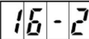 | This function selects the temporary stop switch input. (When the panel reset is selected, temporary stop input is effective only during sewing operation. | 0 : Ineffective1 : Panel reset key2 : Switch on the machine head | 2 | |
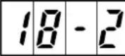 NOTE) NOTE) | This function selects the feed timing. Setting to 1 or 0 will be more effective when the thread is not well-tightened. | 0 : 161° Slow1 : 149°2 : 137°3 : 125°4 : 113°5 : 101° Fast | 2 | Start of feed can be set by the angle of main shaft. |
 | This function selects whether or not the thread breakage detection function is provided. (This function detects at 8 stitches of the start of sewing, and at 3 stitches on the way.) | 0 : Ineffective1 : Effective2 : Not adjusted | 1 | Do not use the setting "2". |
Note) When material is excessively thick, there is a danger of needle breakage if the timing is slow, So, be careful.
| Display | Function | Setting range | State when delivered | Remarks |
 | Wiper sweeping position is set. | 0: Wiper sweeps above the intermediate presser.1: Wiper sweeps below the intermediate presser. | 0 | For LK-1942 only |
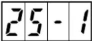 | This function selects whether or not the air pressure detection is provided. | 0: Ineffective1: Effective | 1 | |
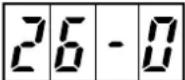 | When the work clamp foot of AMS-206, the origin is compensated. | 0: Without compensation1: With compensation | 0 | Automatic shift of Y=-12 mm imme-diately after the origin retrieval |
 | This function selects the basting mode.Pattern sewing data is read to "jump feed" and curved point to "sewing" respectively and the function is actuated. | 0: Normal1: Basting | 0 | When performing basting, optional thread tension disk raising solenoid is required.(Setting of memory switch No. 28-1: for H type only) |
 | This function selects whether or not thread tension disk No. 2 rising function (optional for H type) or thread drawing function (G and Z types) is provided. | 0: Ineffective1: Disk rising2: Thread drawing | 2 | In either case, connect to J59 of MAIN circuit board. (Cannot be used simultaneously) |
 | This function selects the thread tension controller No. 3.This function selects whether all inverting commands of the pattern data are effective or optional inverting points only are effective. | 0: Ineffective1: All inverting points2: Optional inverting points only | 1 | Setting 1:P95 output Setting 2:P99 output(See the table corresponding to solenoid valve of the optional parts list.) |
 | This function selects timing of presser lifting after completion of sewing. | 0: Presser goes up after thread trimming and returning to the origin.1: Presser goes up immediately after thread trimming. | 0 | When it is set to "1", the cloth can be taken out instantly since the presser goes up immediately after the thread trimming. |
 | This function is not used with LK-1941/42.Do not change the setting. | - | 0 | |
 | This function selects whether or not the needle cooler output is provided. | 0: Ineffective1: Effective | 1 | |
 | This function selects whether or not the thread trimming command control of the pattern data is effective. | 0: Effective1: Ineffective | 0 | Even when it is set to ineffective, it is effective at the time of temporary stop or the like. |
 | This function selects whether or not the thread trimming device control is effective. | 0: Thread trimming is enabled.1: Thread trimming is prohibited. | 0 | |
 | This function sets the control of the delay timing from heat cutter output OFF to wiper ON. Set the value to a larger one whenever the thick thread is used.(Setting is possible in a unit of 50 ms.) | 250 to 950ms | 700 | For heat cutter type only |
 | This function selects whether or not the optional thread clamp device control is effective. | 0: Ineffective1: Effective | 0 | |
 | This function sets the guide cylinder OFF timing of the optional thread clamp device by the number of stitches from the start of sewing. | 2 to 5 stitches | 2 | |
 | This function selects the speed of revolution of the bobbin winder. | 0: High speed (1600 sti/min)1: Low speed (800 sti/min) | 0 | |
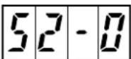 | Selection of the return route to the sewing start point When the effective is set, the machine returns to the sewing start point through the route tracing reversely the sewing pattern. | 0: Ineffective1: Effective | 0 | Set toe the effective when the straight line movement is not possible due to the limitation of the shape of presser or the like. |
IX. OTHERS
1. Sewing pattern
(1) Pattern input device
Pattern can be inputted by using the handy programming device, PGM-7, or PGM-20.
(2) Data ROM for sewing pattern
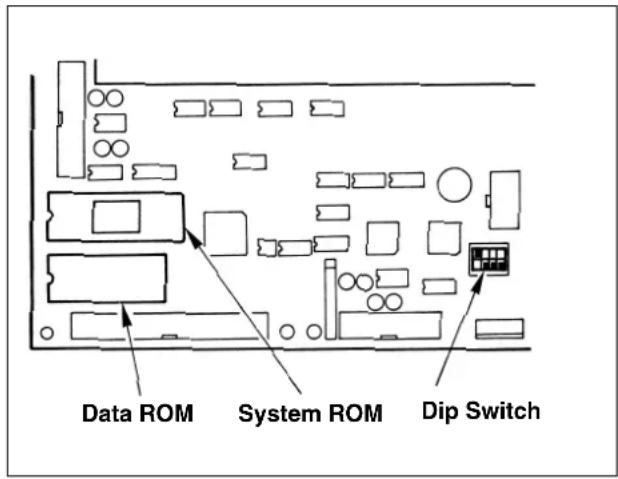

Turn OFF the power before inserting/drawing out the ROM or changing-over the switch.
1) Data ROM is incorporated in U32 on the MAIN circuit board.
When creating a pattern with the PGM-7, confirm that this ROM is incorporated. (The pattern which has been created is recorded in this ROM.) ROM part No.: HLO11940000
(EEP-ROM 58C256)
Write in this ROM as well when creating a pattern with the PGM-20.
2) When using the Data ROM (EEP-ROM 58C65) for AMS-206, turn OFF DIP switch SW1-1.
In addition, when using the presser of AMS-206, change the setting of the memory switch No. 26 to adjust the sewing position.

Be sure to check the setting of DIP switch when replacing the Data ROM. If the setting is mistaken, correct data could not be read and E-1, E-2, or E-8 may appear.
(3) Table of interchangeability of Data ROM (part) of LK-1941/42
| Kind of ROM Usable/not usable | ||
| For LK-1900 27C256 | Not usable | |
| For Ik-1910/20 58C256 | 6 Usable | |
| For AMS-206 58C65 | Usable | |
(4) Making the sewing pattern
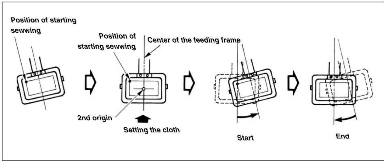
flowchart
graph LR
    A["Start"] --> B["Setting the cloth"]
    B --> C["Position of starting sewwing"]
    C --> D["Position of starting sewwing"]
    D --> E["Center of the feeding frame"]
    E --> F["End"]
1) Receding position of the feeding frame (application of the 2nd origin)
Therer is a case where the feeding frame is slanted and the material is hard to be set in accordance with the material. In this case, it is easier to set the material if the 2nd origin is set to near-by the center of the feeding frame.
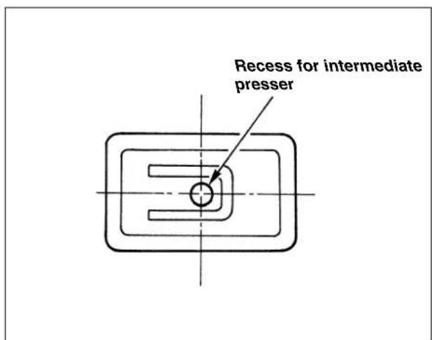
2) When using the feeding frame blank
In case where the lift of the feeding frame is high, the feeding frame is likely to come in contact with the intermediate presser. In this case, it is recommended to set receding position of the presser (2nd origin) described in item 1) and to make a recess for the intermediate presser in the feeding frame blank.
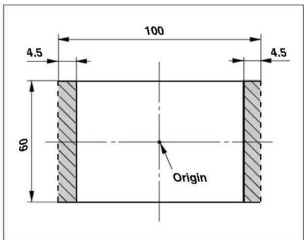
3) Position of the thread trimming
1) Do not enter the thread trimming data in the slant section if possible. There may be a case where the thread is not trimmed.
2) When entering the thread trimming control, set the pitch of the last stitch to 2 mm or more.

The input device is necessary when creating the sewing pattern.
2. Setting the DIP switch
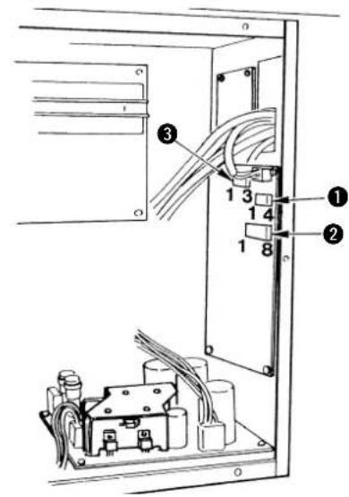
By changing DIP SW1 ①, DIP SW2 ②, and SLIDE SW3 ③ mounted on the control box, the setting can be changed as described in the following table.

- Perform the change of the DIP SW and SLIDE SW after turning OFF the power switch. - Do not turn ON the switch not used yet.
①DIP SW1
| Function | Change of needle bar stop height (It is possible to set ±7 stages by combination of the set value of DIP SW1-1 to -3 and the code setting of DIP SW2-1.) | ||||
| SW1-1 SW1-2 SW1-3 | SW1-4(unused) | Set value | Needle tip height at the time of UP stop | ||
| OFF OFF | OFF OFF | 0(State of delivery) | The height depends on the set value of DIP switch SW2-1 2.DIP SW2-1ON/Needle stop position - highOFF/Needle stop position - low | ||
| ON OFF | OFF OFF 1 | ||||
| OFF ON | OFF OFF 2 | ||||
| ON ON | OFF OFF 3 | ||||
| OFF OFF | ON OFF 4 | ||||
| ON OFF | ON OFF 5 | ||||
| OFF ON | ON OFF 6 | ||||
| ON ON | ON OFF 7 | ||||
②DIP SW2
| Function ON OFF | State of delivery | |||
| SW2-1 | Selection of needle bar UP stop position code | High Low OFF | ||
| SW2-2 | Thread trimming speed setting | 250sti/min 400sti/min ON | ||
| SW2-3 Unused - | - | OFF | ||
| SW2-4 Unused - | - | OFF | ||
| SW2-5 Unused - | - | OFF | ||
| SW2-6 Unused - | - | OFF | ||
| SW2-7 Unused - | - | OFF | ||
| SW2-8 Unused - | - | OFF | ||
③ SLIDE SW3
| Function | State of delivery |
| Unused | 3 side ON |
3. Connection of the optional pedal
※ When using the optional pedal, refer to2-(4) Setting the pedal specifications" described in the item of "Ⅷ. HOW TO USE THE MEMORY SWITCH".
(1) Connection of the 2-step pedal
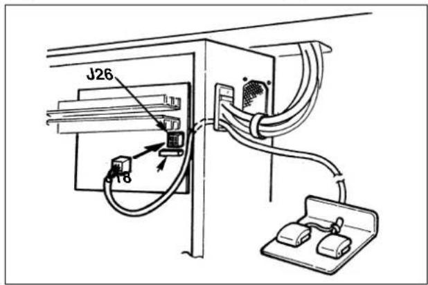
(2) Connection of the PK-57
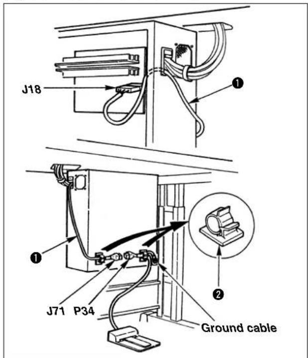
(3) Connection of the 2-step PK pedal
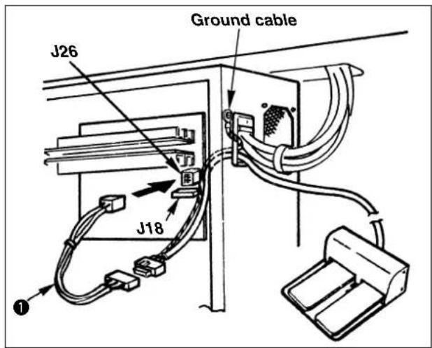
1) Remove the standard pedal cord from J18 connector on the MAIN circuit board.
2) Enter the 2-step pedal cord into the control box and connect it with J26 connector on the MAIN circuit board.
2-step pedal : Part No. M85205800A0
* Memory switch No. 10-1
1) Remove the standard pedal cord from J18 connector on the MAIN circuit board, and connect PK-57 change cable ①.
2) Connect the cord of PK-57 with J71 of PK-57 change cable ① at the rear face of the control box. Then, clamp two places with adhesive clamp ②. Also, tighten with a screw the PK-57 ground cable as illustrated in the figure.
PK-57 : Part No. GPK570010B0
PK-57 change cable : Part No. M90135900A0
Adhesive clamp : Part No. E96076030000
(2 pcs.)
* Memory switch No. 10-2
1) Remove the standard pedal cord from J18 connector on the MAIN circuit board.
2) Enter the 2-step PK pedal cord into the control box, connect it with the 2-step pedal connecting cord asm.①, and connect it with J26 connector on the MAIN circuit board.
Tighten with a screw the ground cable as illustrated in the figure.
2-step PK pedal : Part No. M85905130AA
2-step pedal
connecting cord asm.: Part No. M90315800A0
* Memory switch No. 10-1
(4) Connection of the 3-step pedal
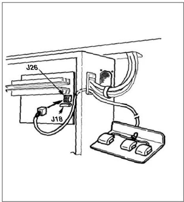
1) Remove the standard pedal cord from J18 connector on the MAIN circuit board.
2) Insert the 3-step pedal cord into the control box and connect it to J26 connector of the MAIN circuit board.
3-step pedal : Part No. M85215800A0
* Memory switch Nos. 10-3 to -5
(5) Connection of the 3-step PK pedal
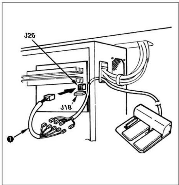
1) Remove the standard pedal cord from J18 connector on the MAIN circuit board.
2) Enter the 3-step PK pedal cord into the control box, connect it with change cable asm. ①, and connect it with J26 connector on the MAIN circuit board. (Refer to the table below for the connection.)
3-step PK pedal : Part No. GPK470010AB
Change cable : Part No. M90255800A0
* Memory switch Nos. 10-3 to 5
| PK-47 Relay cord Signal name | |
| P1 P101 Feeding frame 1 | |
| P2 P102 Feeding frame 2 | |
| P3 P103 Feeding frame 3 | |
| - P104 Not used | |
| P4 P105 Start | |

Either J18 or J26 of MAIN circuit board can be used for the pedal.
Be careful when the optional pedal is used since the machine may fail to work if both connectors are simultaneously connected.
- Table of error indication
| Error indication | Name of error | Description | Corrective measure | Remarks |
| E 1 | Pattern No. error | The specified pattern No. has not been registered in the data ROM. | Check the pattern No. | The service pattern is registered in SYSTEM ROM. |
| E 2 | Enlargement errorPattern reading error | · The sewing pitch is beyond 10 mm.· Data ROM which is used is different from setting of DIP switch. | · Check the scale rate and sewing pitch.· Make sure of setting of SW1-1. | If the setting of SW1-1 is different from Data ROM, reading becomes unstable. |
| E 3 | Needle bar upper position error | The needle bar is shifted from the upper position. | Turn the hand pulley, and return the needle bar to the upper position. | |
| E 4 | Sewing area over | The sewing area is beyond the limit. | Press the reset switch and check the pattern and scale rate. | |
| E 5 | Stop on the way | Stop on the way while the sewing machine is running. | · Re-sewing by retreat of the feed → start· Thread trimming action using the temporary stop switch or reset· Return-to-origin action by reset after thread trimming action | |
| E 6 | Safety switch error | Safety switch is turned OFF.(When the sewing machine head is tilted or the like.) | · Turn OFF the power switch and raise the machine head.· Check the safety switch. | |
| E 7 | Machine lock errorAbnormal voltage error | The main shaft of the sewing machine does not rotate due to some troubles. | · Turn OFF the power switch, and remove the cause of trouble.· Check the power source voltage. | |
| E 8 | Pattern data error | The pattern data reading from the data ROM cannot be made. | · Turn OFF the power switch and remove the cause.· Check the mounting of EEP-ROM(contact failure, direction of mounting, etc.).· Check the setting of SW1-1. | If the setting of SW1-1 is different from Data ROM, reading becomes unstable. |
| E 9 | Needle thread breakage detection error | The needle thread has been broken during sewing. | · Retreat of the feed after threading and re-sewing· Return-to-origin action by reset | |
| E 10 | PGM-7 communication error | Communication with the PGM-7 cannot be performed due to some troubles. | · Turn OFF the power switch and remove the cause.(Contact failure, disconnection of cord, or trouble of circuit board is considered.) | |
| E RR | Air pressure drop error | The air pressure is dropped. | Turn OFF the power switch, and check the air pressure. | |
| E EE | Memory write-in error | The data writing to the memory for the back-up cannot be made. | · Turn OFF the power switch.· Defective memory (Replace the MAIN circuit board.) | |
| E | Time-out error | MAIN circuit board is uncontrollable due to some troubles. | · Turn OFF the power switch.· Defective MAIN circuit board(Replace the MAIN circuit board.) | |
| E H | Overheat error | Temperature in the control box is abnormally high. | Turn OFF the power switch, and check whether the fan filter is clogged, and the power source voltage. Turn ON the power after the temperature has dropped properly. |
Caution : Refer to the Instruction Manual for AW-2D when any error other than the aforementioned ones is displayed with the sewing machine provided with AW-2D.
- Troubles and corrective measures (sewing conditions)
| Trouble | Cause | Corrective measures | Page |
| 1. The needle thread slips off at the start of bar-tacking. | 1Stitches are slipped at the start. | ○Adjust the clearance between the needle and the shuttle to 0.05 to 0.1 mm.○Set soft-start sewing at the start of bartacking.○Change the pitch at the start of sewing. (Increase or decrease.) | 3948 |
| 2The needle thread remaining on the needle after thread trimming is too short. | ○Increase the rising amount of the disk of thread tension controller No. 2.○Increase the rising amount of the disk of auxiliary thread tension.○Increase the tension of the thread take-up spring, or decrease the tension of the thread tension controller No. 1.○Increase the clearance between the needle hole guide and the counter knife. (Knife type)○Lower the counter knife. (Knife type)○Adjust the position of the moving knife. (Hot wire type) | 414122434342 | |
| 3The bobbin thread is too short. | ○Decrease the tension of the bobbin thread.○Increase the clearance between the needle hole guide and the counter knife. (Knife type)○Lower the counter knife. (Knife type) | 224343 | |
| 2. Thread often breaks or synthetic fiber thread splits finely. | 1The hook or the inner hook stopper has scratches. | ○Take it out and remove the scratches using a fine whetstone or buff. | |
| 2The needle hole guide has scratches. | ○Buff or replace it. | ||
| 3Partial catch of thread by hook due to needle deflection | ○Use a hook suitable for the needle count number. | 62 | |
| 4The needle thread tension is too high. | ○Reduce the needle thread tension. | 22 | |
| 5The tension of the thread take-up spring is too high. | ○Reduce the tension. | 22 | |
| 6The synthetic fiber thread melts due to heat generated on the needle. | ○Use silicone oil. | 59 | |
| 7Thread breakage due to partial catch of thread by hook when sewing seat belt | ○Use the needle cooler.○Use an oval needle hole guide. | 6062 | |
| 8Needle stitches in fabric yarn. | ○Use the ball-point needle. | ||
| 3. The needle often breaks. | 1The needle is bent. | ○Replace the bent needle. | |
| 2The needle is too thin for the material. | ○Replace it with a thicker needle according to the material. | ||
| 3Feed timming is excessively slow. | ○Make the feeding timing fast. | 48,50 | |
| 4. Treads are not trimmed. | 1Position of thread trimming is improper. | ○Enter thread trimming at the proper position. | 53 |
| 2The moving knife has been improperly positioned. | ○Correct the position of the moving knife. | 42 | |
| 3The last stitch is skipped. | ○Correct the timing between the needle and the shuttle. | 39 | |
| 4Pitch at the last stitch is too small. | ○Increase the pitch of the last stitch. | ||
| (Knife type)1The counter knife is dull. | ○Replace the counter knife. | ||
| 2The difference in level between the needle hole guide and the counter knife is not enough. | ○Increase the bend of the counter knife. | 43 | |
| (Hot wire type)1Temperature setting is too low. | ○Make the setting high. | 26 | |
| 2The hot wire plate comes in contact with the needle hole guide. | ○Adjust the position of the hot wire plate. | 43 | |
| 5. Stitch skipping often occurs. | 1The motions of the needle and shuttle are not properly synchronized. | ○Correct the positions of the needle and shuttle. | 39 |
| 2The clearance between the needle and shuttle is too large. | ○Correct the positions of the needle and shuttle. | 39 | |
| 3The needle is bent. | ○Replace the bent needle. | ||
| 6. The needle thread comes out on the wrong side of the material. | 1The needle thread tension is not high enough. | ○Increase the needle thread tension.○Delay the feed timing. | 2248,50 |
| 2The needle thread after thread trimming is too long. | ○Increase the tension of the thread tension controller No. 1. | 22 | |
| 7. When synthetic fiber thread is used, at the start or end of sewing, needle thread rises or remaining of needle thread is excessive. | 1In case of synthetic fiber thread, the thread is harder than other threads and penetration resistance to material is small. | ○When making a pattern, set the sewing pitch at the start and end of sewing to 1 mm or less. |
6. The optional parts
| Name of Parts | Type | Part No. | Remarks |
Feed plate blank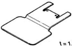 2 2 | Without knurl/Without processed | 14224109 | |
| With knurl/Without processed | 14224000 | ||
Feeding frame blank   | Solid type feeding frame/with knurl | B2553210D0A | |
| Solid type feeding frame/without knurl | B2553210D0B | ||
| Separate type feeding frame/without knurl | B2554210D0A | ||
| Separate type feeding frame/with knurl | B2554210D0B | ||
| Separate type feeding frame/with knurl | B2554210D0C | ||
Silicon tank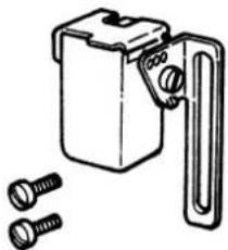 | B92118500A0SS7110840SPx 2B1131850000C | ||
| Name of Parts Type | Part No. | Remarks | |
Needle cooler asm.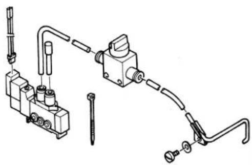 | 14225056 | ||
Thread tension controller No. 3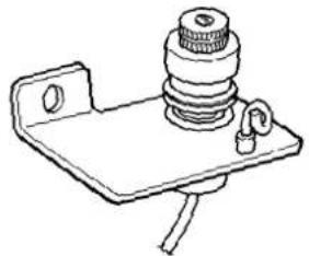 | B50192220B0PV150209000PX50001400014204754 | ||
Thread clamp device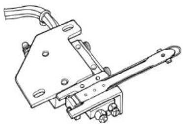 | 14445050 | Effective to prevent stitch skipping at the start of sewing. |
Table corresponding to the solenoid valve output
In csse of the optional device for which the solenoid valve is used, connect the solenoid valve to MAIN circuit board referring to the figure on the right side.

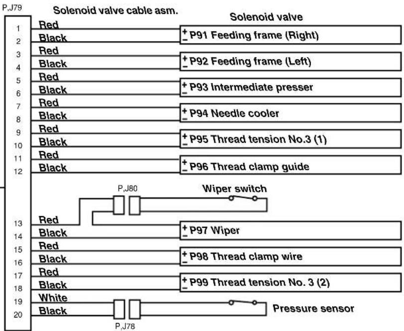
flowchart
graph TD
    A["Solenoid valve cable asm. Red"] --> B["Black"]
    B --> C["P91 Feeding frame (Right)"]
    C --> D["Red"]
    D --> E["Black"]
    E --> F["P92 Feeding frame (Left)"]
    F --> G["Red"]
    G --> H["Black"]
    H --> I["P93 Intermediate presser"]
    I --> J["Red"]
    J --> K["Black"]
    K --> L["P94 Needle cooler"]
    L --> M["Red"]
    M --> N["Black"]
    N --> O["P95 Thread tension No.3 (1)"]
    O --> P["Red"]
    P --> Q["Black"]
    Q --> R["P96 Thread clamp guide"]
    R --> S["White"]
    S --> T["Black"]
    T --> U["PJ78"]
    U --> V["Pressure sensor"]
| Name of Parts | Type | Part No. | Remarks |
Solid type work clamp foot compl.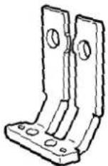 | 14437255 | ||
Feed plate blank for belt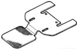 t=1.2 t=1.2 | With knurl/Without processed | 14444202 | Knurl is coarser than that of the normal feed plate blank and effective for preventing materials from slipping. In addition, positioning of belt can be performed by using the feed plate guide. This is the guide for determining the position when sewing belt. |
Feed plate guide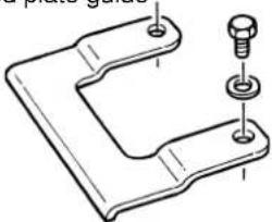 | 14444301SM9040603SC x2 WP0450826SC x2 | This guide is used as a set together with 14444202, feed plate blank for belt and feeding frame blanks for belt (14444004 and 14444103). | |
Feeding frame blank for belt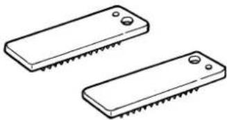 | Separate type feeding frame, right/with knurl/without processed | 14444004 | Knurl is coarser than that of the normal feeding frame blank and effective for preventing materials from slipping. |
| Separate type feeding frame, left/with knurl/without processed | 14444103 | ||
Wiper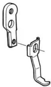 | Reverse sweeping wiper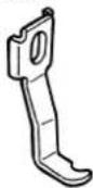 | 14446009 | Wiper waiting position is reverse to the normal position. This is used when the sewing product interferes with the wiper. (It is necessary to change connection in the air piping drawing.) |
Wiper for retaining thread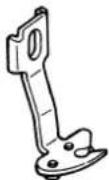 | 14446157 | This wiper lightly retains needle thread in order to prevent needle thread at the start of sewing from being caught under the presser. | |
Wiper base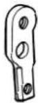 | 14445902 | Be sure to replace the wiper base as a set when using the reverse sweeping wiper or the wiper for retaining thread. |
7. Table of the gauge parts
| Name of Parts Type | Part No. | Remarks | |
Needle hole guide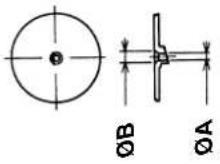 | A=3.0 B=4.0For knife type thread trimming | 14439608 | Standard for H type |
| A=4.0 B=5.0For knife type thread trimming | 14439707 | Standard for G type | |
| A=3 x 4.4 Oval B=5.0For hot wire type thread trimming | 14440002 | For Z type (for seat belt) | |
| A=2.0 B=3.0For knife type thread trimming | 14439400 | ||
| A=2.3 B=3.3For knife type thread trimming | 14439509 | ||
| A=3 x 4.4 Oval B=5.0For knife type thread trimming | 14440101 | for seat belt | |
| A=3.0 B=4.0For hot wire type thread trimming | 14439806 | ||
| A=4.0 B=5.0For hot wire thread trimming | 14439905 | ||
Intermediate presser (For LK-1942 only)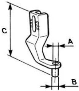 | A=3.5 B=5.5C=39.0 | 14433601 | Standard for G type |
| A=2.2 B=3.6C=39.0 | B160122000J | Standard for H type | |
Hook | Lubricating hook AHook gib is long. | 14436554 | Standard for H typeCan be used up to needle size #18 to #20.(In case of ORGAN needle) |
| Lubricating hook BHook gib is long. | 14436703 | OptionalCan be used up to needle size #21 to #23.(In case of ORGAN needle) | |
 | Lubricating hook CHook gib is short. | 14436307 | Standard for G typeCan be used up to needle size #21 to #23.(In case of ORGAN needle) |
| Lubricating hook DHook gib is short. | 14436158 | Standard for Z typeCan be used up to needle size #24 to #26.(In case of ORGAN needle) |
8. Drawing of the table
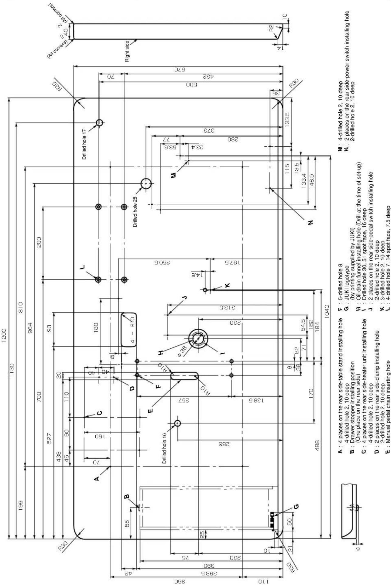
Table for the machine provided with AW device
* Dimensions and specifications which are not indicated are the same as those of the drawing of table on the previous page.
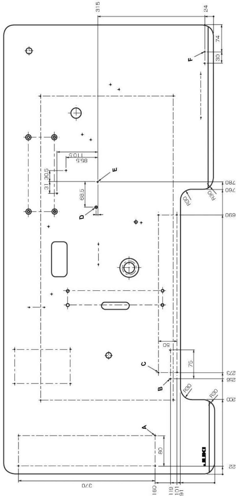
A:4-03.2 on the bottom surface, depth 15
B:2-03.2 on the bottom surface, depth 15
C:4-03.2, depth 15
D:6.5, penetration
E:3-03.2, depth 15
F:2-03.2 on the bottom surface, depth 15
DEUTSCH
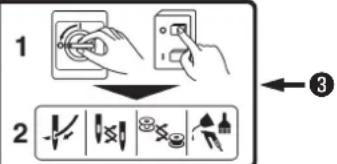


Hazardous voltage will cause injury.
Turn off main switch and unplug power cord and wait at least 5 minutes before opening this cover.

GEFAHR
natural_image
Technical line drawing of a mechanical or electrical cabinet with fans and control panel (no text or symbols)
Vorsicht
natural_image
Technical line drawing of a mechanical assembly with wiring and mounting bracket (no text or symbols)natural_image
Technical diagram of a mechanical assembly with bolted components and a magnified inset showing a circular component (no text or labels)flowchart
graph LR
    A["READY"] --> B["Target Symbol"]
    B --> C["SEWING"]
1-Pedal-Typ
natural_image
Technical diagram of a mechanical device with two circular insets showing close-ups of components (no text or symbols)flowchart
graph TD
    A["P 1"] --> B["READY"]
    B --> C["SEWING"]
    B --> D["↓"]
    D --> E["Machine with sewing machine"]
    E --> F["↓"]
    F --> G["READY"]
    G --> H["SEWING"]
    G --> I["↓"]
    I --> J["Machine with sewing machine"]
    J --> K["↓"]
    K --> L["Machine with sewing machine"]
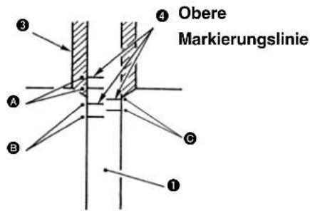
natural_image
Simple line drawing of a test tube with arrows indicating direction, no text or symbols presentnatural_image
Simple line drawing of a cylindrical object with a curved arrow indicating rotation, no text or symbols present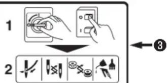
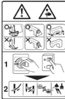


Hazardous voltage will cause injury.
Turn off main switch and unplug power cord and wait at least 5 minutes before opening this cover.

DANGER
natural_image
Technical line drawing of a mechanical assembly with wiring and a close-up view (no text or symbols)Type à 1 pédale
natural_image
Technical diagram of a mechanical assembly with two circular insets showing close-up views of components (no text or labels)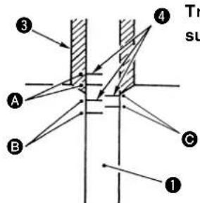
natural_image
Technical diagram showing mechanical assembly with tool and component (no text or symbols)natural_image
Simple line drawing of a test tube with arrows indicating direction (no text or symbols)natural_image
Mechanical assembly diagram showing a shaft and housing component (no text or labels)Bloc-tension n° 2
natural_image
Simple line drawing of a cylindrical object with a curved arrow indicating rotation, no text or symbols present
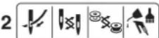

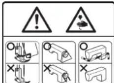

natural_image
Technical line drawing of a mechanical assembly with wiring and mounting bracket (no text or symbols)(13) Modo de conectar la manguera de aire
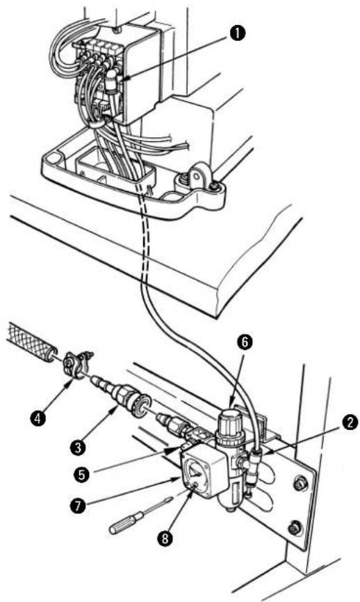
natural_image
Technical line drawing of a mechanical clamp or bracket assembly with a smartphone mounted on a base (no text or symbols present)natural_image
Technical diagram of a mechanical assembly with bolted components and a magnified inset showing internal components (no text or labels)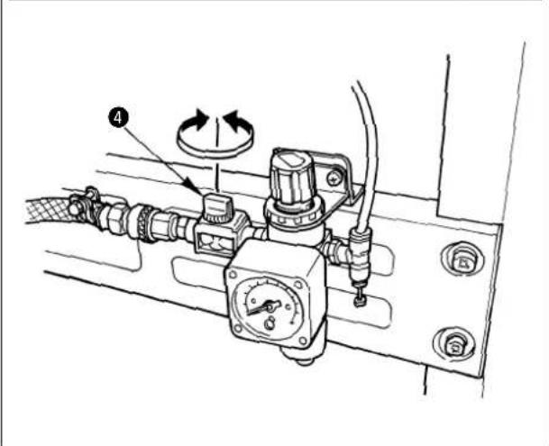
1) Pulse la tecla
Tipo de 1-pedal
natural_image
Technical diagram of a mechanical assembly with two circular insets showing close-up views of components (no text or symbols)flowchart
graph TD
    A["P 1"] --> B["READY"]
    B --> C["SEWING"]
    B --> D["↓"]
    D --> E["Machine with sewing machine"]
    E --> F["↓"]
    F --> G["READY"]
    G --> H["SEWING"]
    G --> I["↓"]
    I --> J["Machine with sewing machine"]
    J --> K["↓"]
    K --> L["P 3"]
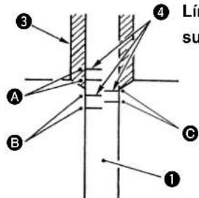
natural_image
Simple line drawing of a test tube with arrows indicating light direction (no text or symbols)Línea subgrayada
natural_image
Simple line drawing of a cylindrical object with an arrow indicating rotation, no text or symbols present4) After setting, register using the Ⓞ key.
①Interruptor DIP SW1
②Interruptor DIP SW2
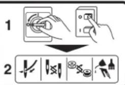

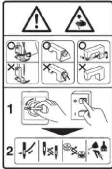


natural_image
Technical line drawing showing a mechanical assembly with wiring and a close-up of a component (no text or symbols present)natural_image
Technical diagram of a mechanical assembly with no visible text or symbols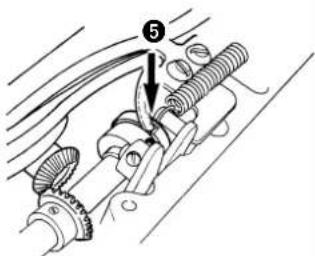
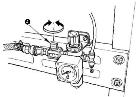
Tipo a 1 pedale
natural_image
Technical diagram of a mechanical assembly with two circular insets showing close-up views of components (no text or labels)natural_image
Technical line drawing of a mechanical assembly with directional arrows and labeled component (no text or symbols)natural_image
Mechanical assembly diagram showing a shaft and housing component (no text or labels)natural_image
Simple line drawing of a mechanical component with directional arrows indicating motion (no text or symbols)natural_image
Technical line drawing showing a mechanical assembly with wiring and a close-up view of a component (no text or symbols present)2. 操作箱开关的名称
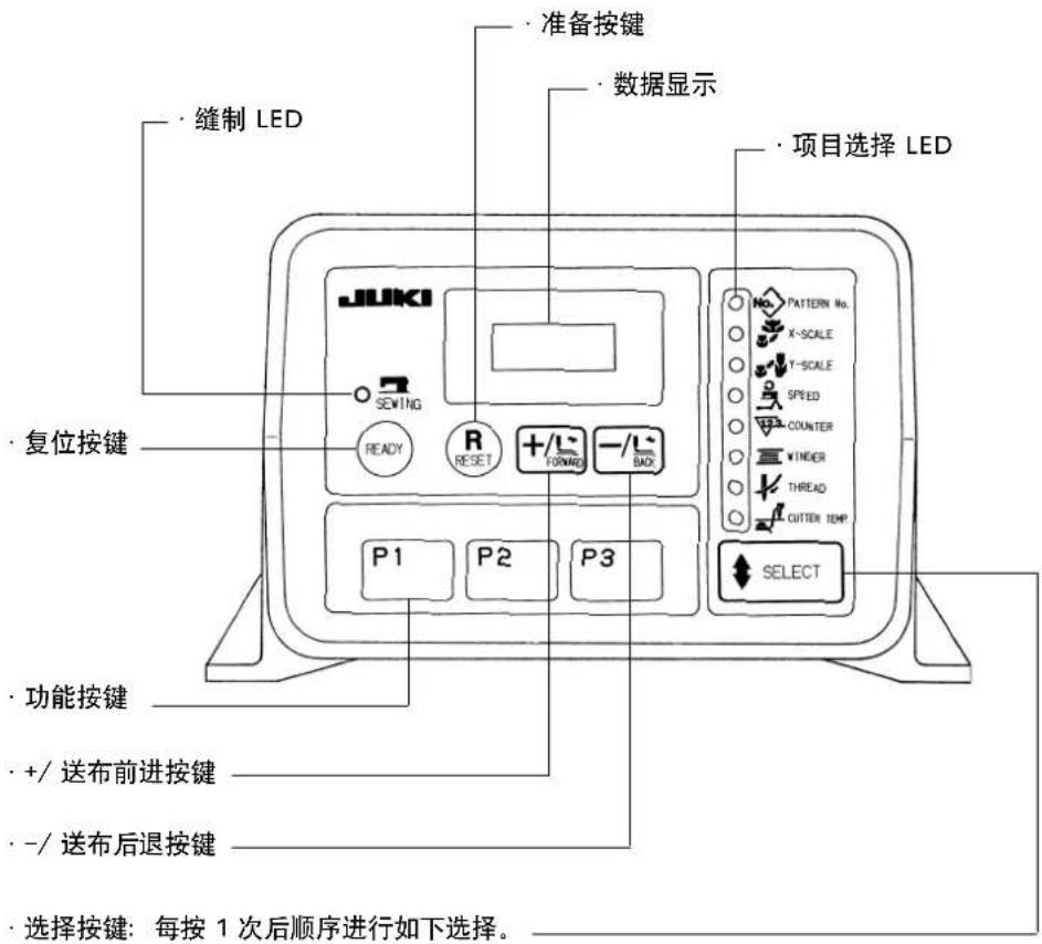
natural_image
Technical line drawing of an electrical enclosure with wiring and a tool inserted (no text or symbols)natural_image
Technical line drawing of a mechanical assembly with a smartphone mounted on a bracket (no text or symbols)请一定安装眼睛保护罩①后使用缝纫机。
(15) 线架装置的安装
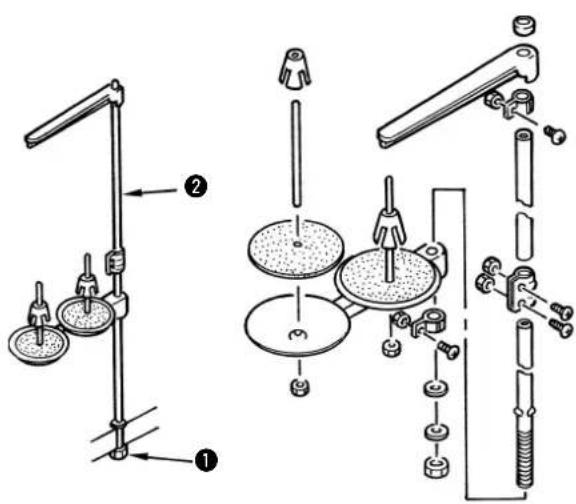
natural_image
Technical diagram of a mechanical assembly with bolted components and a magnified inset showing internal components (no text or labels)2)请往旋梭轴面③上滴一滴机油。
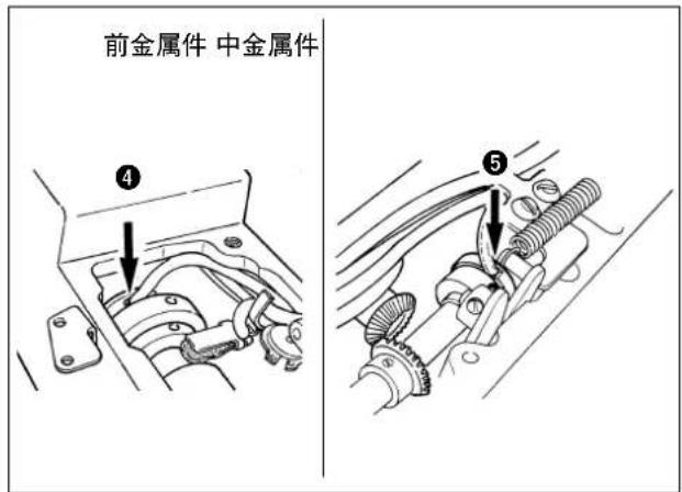
3. 上线的穿线方法
注意
有因被夹针等把手指、手弄伤的危险,请不要把手指等伸到压脚的下边。
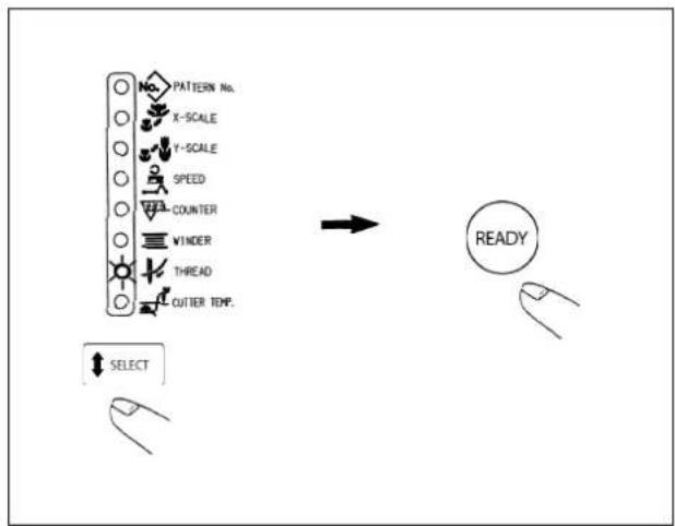
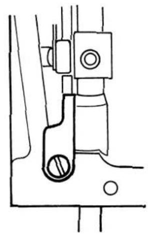
natural_image
Technical line drawing of a mechanical assembly with no visible text or symbolsflowchart
graph LR
    A["READY"] --> B[" Sunset Icon"]
    B --> C["SEWING"]
单踏板
natural_image
Technical line drawing showing a sewing machine and its corresponding mechanical component labeled A and B (no text or symbols beyond labels)压脚
D
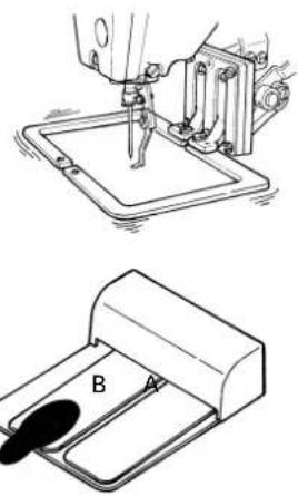
natural_image
Technical line drawing showing a sewing machine and a mechanical device with labeled component B (no text or symbols present)起动
D
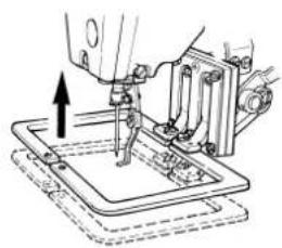
natural_image
Technical line drawing of a sewing machine needle stitching a flat base (no text or symbols)缝制结束
双联PK踏板
natural_image
Technical diagram of a mechanical device with two views showing internal components (no text or symbols present)如图所示进行穿线,卷绕底线。
6-2. 只卷绕底线时
注意
natural_image
Line drawing of a sewing machine needle stitching fabric, with hands operating the machine (no text or symbols visible)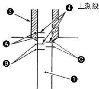
natural_image
Technical diagram showing mechanical assembly with tool and component (no text or symbols)请每周清扫控制箱风扇的滤清器②。
natural_image
Simple line drawing of a cylindrical object with an arrow indicating rotation or movement, no text or symbols present.使用 5 根保险丝。
natural_image
Pure electrical circuit lines without any symbols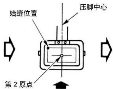
起动

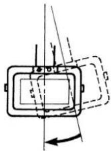
natural_image
Pure technical diagram of a mechanical component with no visible text, numbers, or symbols结束
1)压脚躲避位置(第二原点的灵活运用)
SEWING MACHINERY BUSINESS UNIT
2-11-1, TSURUMAKI, TAMA-SHI,
Copyright © 2011-2013 JUKI CORPORATION
- All rights reserved throughout the world.
- Alle Rechte weltweit vorbehalten.
- Tous droits réservés partout dans le monde.
- Reservados todos derechos en el mundo entero.
• Tutti i diritti sono riservati in tutto il mondo.
· 版权所有,严禁擅自转载、翻印本书的内容。
Please do not hesitate to contact our distributors or agents in your area for further information when necessary.
* The description covered in this instruction manual is subject to change for improvement of the commodity without notice.
Bitte wenden Sie sich an unsere Händler oder Vertreter in Ihrer Nähe, wenn Sie weitere Informationen benötigen.
* Änderungen der in dieser Betriebsanleitung enthaltenen Beschreibungen, die der Verbesserung des Produktes dienen, bleiben vorbehalten.
Pour plus d'information, n'hésitez pas à consulter nos distributeurs ou agents dans votre région.
* Les spécifi cations données dans le présent Manuel d'utilisation sont sujettes à modifi cation sans préavis.
Sirvase ponerse en contacto con nuestros distribuidores o agentes en su área siempre que necesite alguna información más detallada.
* La descripción que se de en este manual de instrucciones está sujeta a cambio sin previo aviso por razones de mejora de la mercancía.
Per ulteriore informazione, si prega di non esitare a mettersi in contatto con nostri distributori o agenti vostra area quando necessario.
* Le descrizioni contenute in questo manuale d'istruzioni sono soggette a modifi che senza alcun preavviso.
对本产品如有不明之处,请向代理店或本公司营业部门询问。
※ 本使用说明书中的规格因改良而发生变更,请订货时确认。