
LK-1930 - Sewing machine JUKI - Free user manual and instructions
Find the device manual for free LK-1930 JUKI in PDF.

| Product Type | Industrial electronic zigzag sewing machine |
| Brand | JUKI |
| Model | LK-1930 |
| Dimensions (W×D×H) | 1,200 mm × 700 mm × 1,160 mm (with standard table and stand) |
| Weight | Head: 46 kg, Control box: 18 kg |
| Power Supply | Mains voltage ±10%, 50/60 Hz, consumption 600 W |
| Max Sewing Speed | 2,500 stitches/min (with stitch length ≤ 3 mm) |
| Stitch Length | 0.1 to 12.7 mm (adjustable in 0.1 mm steps) |
| Needle | DP×5, DP×17 |
| Hook | Folding semi-rotary hook (oil wick lubrication) |
| Sewing Area (X×Y) | 100 mm × 60 mm |
| Memory Support | 3.5-inch micro floppy disk (2DD/2HD) or EEP-ROM (32 KB) |
| Main Functions | Read/write configuration, enlargement/reduction (1–400%), bobbin thread counter, temporary stop, thread break detection, second origin, needle up stop |
| Motor | Servo motor 550 W |
| Air Pressure (pneumatic type) | 0.5 to 0.55 MPa |
| Lubrication | JUKI New Defrix Oil No. 2; drain oil from crankcase |
| Maintenance | Weekly cleaning of fan filter, periodic lubrication, cable inspection |
| Safety | Eye guard, needle guard, belt cover, emergency stop, mandatory grounding |
| Operating Temperature | 5 to 35 °C, relative humidity 35–85% (non-condensing) |
| Optional Accessories | Silicone oil reservoir, tension disc opening device, needle cooler, drive frame blanks |
Frequently Asked Questions - LK-1930 JUKI
User questions about LK-1930 JUKI
0 question about this device. Answer the ones you know or ask your own.
Ask a new question about this device
Download the instructions for your Sewing machine in PDF format for free! Find your manual LK-1930 - JUKI and take your electronic device back in hand. On this page are published all the documents necessary for the use of your device. LK-1930 by JUKI.
USER MANUAL LK-1930 JUKI
TO ENSURE SAFE USE OF YOUR SEWING MACHINE
For the sewing machine, automatic machine and ancillary devices (hereinafter collectively referred to as "machine"), it is inevitable to conduct sewing work near moving parts of the machine. This means that there is always a possibility of unintentionally coming in contact with the moving parts. Operators who actually operate the machine and maintenance personnel who are involved in maintenance and repair of the machine are strongly recommended to carefully read to fully understand the following SAFETY PRECAUTIONS before using/maintaining the machine. The content of the SAFETY PRECAUTIONS includes items which are not contained in the specifications of your product.
The risk indications are classified into the following three different categories to help understand the meaning of the labels. Be sure to fully understand the following description and strictly observe the instructions.
(I) Explanation of risk levels
| DANGER :This indication is given where there is an immediate danger of death or serous injury if the person in charge or any third party mishandles the machine or does not avoid the dangerous situation when operating or maintaining the machine. |
| WARNING :This indication is given where there is a potentiality for death or serious injury if the person in charge or any third party mishandles the machine or does not avoid the dangerous situation when operating or maintaining the machine. |
| CAUTION :This indication is given where there is a danger of medium to minor injury if the person in charge or any third party mishandles the machine or does not avoid the dangerous situation when operating or maintaining the machine. |
| Items requiring special attention. |
(II) Explanation of pictorial warning indications and warning labels
| Pictorial warning indication | There is a risk of injury if contacting a moving section. | Pictorial warning indication | Be aware that holding the sewing machine during operation can hurt your hands. | ||
| There is a risk of electrical shock if contacting a high-voltage section. | There is a risk of entanglement in the belt resulting in injury. | ||||
| There is a risk of a burn if contacting a high-temperature section. | There is a risk of injury if you touch the button carrier. | ||||
| Be aware that eye deficiency can be caused by looking directly at the laser beam. | Indication label | The correct direction is indicated. | |||
| There is a risk of contact between your head and the sewing machine. | Connection of a earth cable is indicated. | ||||
| Warning label | 1→2→3 1·There is the possibility that slight to serious injury or death may be caused. ·There is the possibility that injury may be caused by touching moving part. 2·To perform sewing work with safety guard. ·To perform sewing work with safety cover. ·To perform sewing work with safety protection device. 3·Be sure to turn the power OFF before carrying out "machine-head threading", "needle changing", "bobbin changing" or "olling and cleaning". | ←1 ←2 ←3 | |||
| Electrical-shock danger label | 危险 高电压部分以触电、火灾等为 电源切口、5分以上加到500V以下为止。 | Hazardous voltage will cause injury. Turn off main switch and unplug power cord and wait at least 5 minutes before opening this cover. | |||

DANGER
- When it is necessary to open the control box containing electrical parts, be sure to turn the power off and wait for five minutes or more before opening the cover in order to prevent accident leading to electrical shock.

CAUTION
Basic precaution
- Be sure to read the instruction manual and other explanatory documents supplied with accessories of the machine before using the machine. Carefully keep the instruction manual and the explanatory documents at hand for quick reference.
- The content of this section includes items which are not contained in the specifications of your product.
- Be sure to wear safety goggles to protect against accident caused by needle breakage.
- Those who use a heart pacer have to use the machine after consultation with a medical specialist.
Safety devices and warning labels
- Be sure to operate the machine after verifying that safety device(s) is correctly installed in place and works normally in order to prevent accident caused by lack of the device(s).
- If any of the safety devices is removed, be sure to replace it and verify that it works normally in order to prevent accident that can result in personal injury or death.
- Be sure to keep the warning labels adhered on the machine clearly visible in order to prevent accident that can result in personal injury or death. If any of the labels has stained or come unstuck, be sure to change it with a new one.
Application and modification
- Never use the machine for any application other than its intended one and in any manner other than that prescribed in the instruction manual in order to prevent accident that can result in personal injury or death. JUKI assumes no responsibility for damages or personal injury or death resulting from the use of the machine for any application other than the intended one.
- Never modify and alter the machine in order to prevent accident that can result in personal injury or death. JUKI assumes no responsibility for damages or personal injury or death resulting from the machine which has been modified or altered.
Education and training
- In order to prevent accident resulting from unfamiliarity with the machine, the machine has to be used only by the operator who has been trained/educated by the employer with respect to the machine operation and how to operate the machine with safety to acquire adequate knowledge and operation skill. To ensure the above, the employer has to establish an education/training plan for the operators and educate/train them beforehand.
Items for which the power to the machine has to be turned off
Turning the power off: Turning the power switch off, then removing the power plug from the outlet. This applies to the following.
- Be sure to immediately turn the power off if any abnormality or failure is found or in the case of power failure in order to protect against accident that can result in personal injury or death.
- To protect against accident resulting from abrupt start of the machine, be sure to carry out the following operations after turning the power off. For the machine incorporating a clutch motor, in particular, be sure to carry out the following operations after turning the power off and verifying that the machine stops completely.
2-1. For example, threading the parts such as the needle, looper, spreader etc. which have to be threaded, or changing the bobbin.
2-2. For example, changing or adjusting all component parts of the machine.
2-3. For example, when inspecting, repairing or cleaning the machine or leaving the machine.
- Be sure to remove the power plug by holding the plug section instead of the cord section in order to prevent electrical-shock, earth-leakage or fire accident.
- Be sure to turn the power off whenever the machine is left unattended between works.
- Be sure to turn the power off in the case of power failure in order to prevent accident resulting of breakage of electrical components.
PRECAUTIONS TO BE TAKEN IN VARIOUS OPERATION STAGES
Transportation
- Be sure to lift and move the machine in a safe manner taking the machine weight in consideration. Refer to the text of the instruction manual for the mass of the machine.
- Be sure to take sufficient safety measures to prevent falling or dropping before lifting or moving the machine in order to protect against accident that can result in personal injury or death.
- Once the machine has been unpacked, never re-pack it for transportation to protect the machine against breakage resulting from unexpected accident or dropping.
Unpacking
- Be sure to unpack the machine in the prescribed order in order to prevent accident that can result in personal injury or death. In the case the machine is crated, in particular, be sure to carefully check nails. The nails have to be removed.
- Be sure to check the machine for the position of its center of gravity and take it out from the package carefully in order to prevent accident that can result in personal injury or death.
Installation
(I) Table and table stand
- Be sure to use JUKI genuine table and table stand in order to prevent accident that can result in personal injury or death. If it is inevitable to use a table and table stand which are not JUKI genuine ones, select the table and table stand which are able to support the machine weight and reaction force during operation.
- If casters are fitted to the table stand, be sure to use the casters with a locking mechanism and lock them to secure the machine during the operation, maintenance, inspection and repair in order to prevent accident that can result in personal injury or death.
(II) Cable and wiring
- Be sure to prevent an extra force from being applied to the cable during the use in order to prevent electrical-shock, earth-leakage or fire accident. In addition, if it is necessary to cable near the operating section such as the V-belt, be sure to provide a space of 30mm or more between the operating section and the cable.
- Be sure to avoid starburst connection in order to prevent electrical-shock, earth-leakage or fire accident.
- Be sure to securely connect the connectors in order to prevent electrical-shock, earth-leakage or fire accident. In addition, be sure to remove the connector while holding its connector section.
(III) Grounding
- Be sure to have an electrical expert install an appropriate power plug in order to prevent accident caused by earth-leakage or dielectric strength voltage fault. In addition, be sure to connect the power plug to the grounded outlet without exceptions.
- Be sure to ground the earth cable in order to prevent accident caused by earth leakage.
(IV) Motor
- Be sure to use the specified rated motor (JUKI genuine product) in order to prevent accident caused by burnout.
- If a commercially available clutch motor is used with the machine, be sure to select one with an entanglement preventive pulley cover in order to protect against being entangled by the V-belt.
Before operation
- Be sure to make sure that the connectors and cables are free from damage, dropout and looseness before turning the power on in order to prevent accident resulting in personal injury or death.
- Never put your hand into the moving sections of the machine in order to prevent accident that can result in personal injury or death. In addition, check to be sure that the direction of rotation of the pulley agrees with the arrow shown on pulley.
- If the table stand with casters is used, be sure to secure the table stand by locking the casters or with adjusters, if provided, in order to protect against accident caused by abrupt start of the machine.
During operation
- Be sure not to put your fingers, hair or clothing close to the moving sections such as the handwheel, hand pulley and motor or place something near those sections while the machine is in operation in order to prevent accident caused by entanglement that can result in personal injury or death.
- Be sure not to place your fingers near the surround area of the needle or inside the thread take-up lever cover when turning the power on or while the machine is in operation in order to prevent accident that can result in personal injury or death.
- The machine runs at a high speed. Never bring your hands near the moving sections such as looper, spreader, needle bar, hook and cloth trimming knife during operation in order to protect your hands against injury. In addition, be sure to turn the power off and check to be sure that the machine completely stops before changing the thread.
-
Be careful not to allow your fingers or any other parts of your body to be caught between the machine and table when removing the machine from or replacing it on the table in order to prevent accident that can result in personal injury or death.
-
Be sure to turn the power off and check to be sure that the machine and motor completely stop before removing the belt cover and V-belt in order to prevent accident caused by abrupt start of the machine or motor.
- If a servomotor is used with the machine, the motor does not produce noise while the machine is at rest. Be sure not to forget to turn the power off in order to prevent accident caused by abrupt start of the motor.
- Never use the machine with the cooling opening of the motor power box shielded in order to prevent fire accident by overheat.
Lubrication
- Be sure to use JUKI genuine oil and JUKI genuine grease to the parts to be lubricated.
- If the oil adheres on your eye or body, be sure to immediately wash it off in order to prevent inflammation or irritation.
- If the oil is swallowed unintentionally, be sure to immediately consult a medical doctor in order to prevent diarrhea or vomiting.
Maintenance
- In prevention of accident caused by unfamiliarity with the machine, repair and adjustment has to be carried out by a service technician who is thoroughly familiar with the machine within the scope defined in the instruction manual. Be sure to use JUKI genuine parts when replacing any of the machine parts. JUKI assumes no responsibility for any accident caused by improper repair or adjustment or the use of any part other than JUKI genuine one.
- In prevention of accident caused by unfamiliarity with the machine or electrical-shock accident, be sure to ask an electrical technician of your company or JUKI or distributor in your area for repair and maintenance (including wiring) of electrical components.
- When carrying out repair or maintenance of the machine which uses air-driven parts such as an air cylinder, be sure to remove the air supply pipe to expel air remaining in the machine beforehand, in order to prevent accident caused by abrupt start of the air-driven parts.
- Be sure to check that screws and nuts are free from looseness after completion of repair, adjustment and part replacement.
- Be sure to periodically clean up the machine during its duration of use. Be sure to turn the power off and verify that the machine and motor stop completely before cleaning the machine in order to prevent accident caused by abrupt start of the machine or motor.
- Be sure to turn the power off and verify that the machine and motor stop completely before carrying out maintenance, inspection or repair of the machine. (For the machine with a clutch motor, the motor will keep running for a while by inertia even after turning the power off. So, be careful.)
- If the machine cannot be normally operated after repair or adjustment, immediately stop operation and contact JUKI or the distributor in your area for repair in order to prevent accident that can result in personal injury or death.
- If the fuse has blown, be sure to turn the power off and eliminate the cause of blowing of the fuse and replace the blown fuse with a new one in order to prevent accident that can result in personal injury or death.
- Be sure to periodically clean up the air vent of the fan and inspect the area around the wiring in order to prevent fire accident of the motor.
Operating environment
- Be sure to use the machine under the environment which is not affected by strong noise source (electromagnetic waves) such as a high-frequency welder in order to prevent accident caused by malfunction of the machine.
- Never operate the machine in any place where the voltage fluctuates by more than "rated voltage ± 10% " in order to prevent accident caused by malfunction of the machine.
- Be sure to verify that the air-driven device such as an air cylinder operates at the specified air pressure before using it in order to prevent accident caused by malfunction of the machine.
- To use the machine with safety, be sure to use it under the environment which satisfies the following conditions:
Ambient temperature during operation 5^ to 35^
Relative humidity during operation 35% to 85%
- Dew condensation can occur if bringing the machine suddenly from a cold environment to a warm one. So, be sure to turn the power on after having waited for a sufficient period of time until there is no sign of water droplet in order to prevent accident caused by breakage or malfunction of the electrical components.
- Be sure to stop operation when lightning flashes for the sake of safety and remove the power plug in order to prevent accident caused by breakage or malfunction of the electrical components.
- Depending on the radio wave signal condition, the machine may generate noise in the TV or radio. If this occurs, use the TV or radio with kept well away from the machine.
- In order to ensure the work environment, local laws and regulations in the country where the sewing machine is installed shall be followed.
In the case the noise control is necessary, an ear protector or other protective gear should be worn according to the applicable laws and regulations.
- Disposal of products and packages and treatment of used lubricating oil should be carried out properly according to the relevant laws of the country in which the sewing machine is used.
Precautions to be taken so as to use the LK-1930 more safely
| 1. To avoid electrical shock hazards, neither open the cover of the electrical box for the motor nor touch the components mounted inside the electrical box. 2. After changing the pattern, make sure the needle entry point. If the pattern is protruded from the work clamp feet, the needle will interfere with the work clamp feet during sewing, and it is dangerous due to the needle breakage or the like. | |
| 1. So as to prevent possible accidents caused by abrupt start of the sewing machine, depress the start switch after ascertaining that there is no interfering thing under the needle when winding the bobbin thread. 2. So as to prevent possible accidents caused by abrupt start of the sewing machine, never place your fingers under the feeding frame since the feeding frame automatically comes down when the pattern is changed, the needle threading switch is ON, the bobbin thread winding switch is ON or the feeding frame switch is ON. 3. Be aware that the feeding frame will go up if you turn OFF the power while the sewing machine is in operation. So, do not place your hands near the presser foot. 4. Be careful of handling this product so as not to pour water or oil, shock by dropping, and the like since this product is a precision instrument. 5. This is a Class A product. In a domestic environment this product may cause radio interference, in which case the user may be required to make corrective actions. |
Safety devices and warning labels
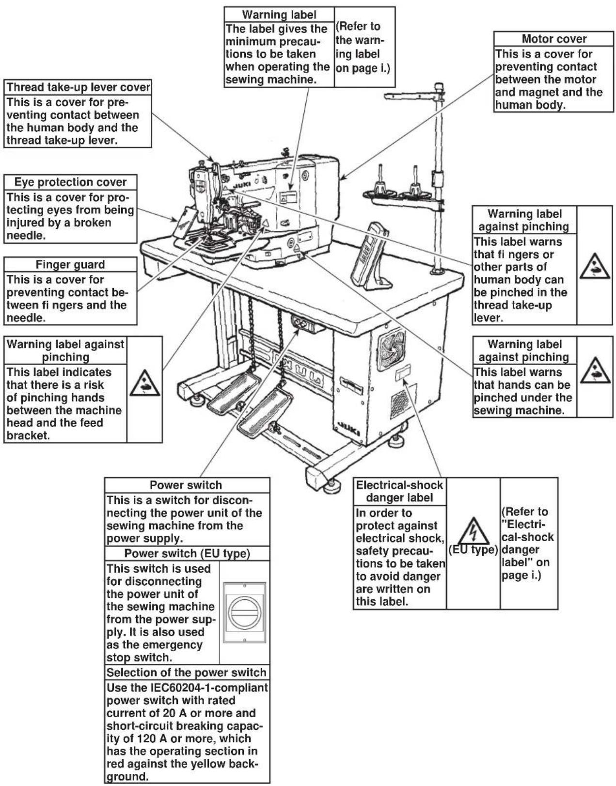

CAUTION
In addition, be aware that the safety devices such as the "eye protection cover" and "finger guard" are sometimes omitted in the sketches, illustrations and figures included in the Instruction Manual for the explanation's sake. In the practical use, never remove those safety devices.
DECLARATION OF INCORPORATION OF PARTLY COMPLETED MACHINERY
We hereby declare that the sewing machine (sewing head) described below;
- Must not be put into service until the machinery to which it is incorporated has been declared in conformity with the provisions of the Directive 2006/42/EC, and
- Conforms to the essential requirements of the Directive 2006/42/EC, described in the technical documentation, and
- To be prepared with the above technical documentation compiled in accordance with part B of Annex VII, and
- Also to conform to the RoHS Directive 2011/65/EU
- Relevant information on which should be transmitted in response to a reasoned request by the national authorities, by the electronic method or other according to the request.
Model LK-1910, LK-1920, LK-1930
Description Industrial Sewing Machine
Function make stitches and sew
Applied harmonized standards, in particular :
EN ISO12100, EN 60204-31, EN ISO10821, EN 50581
Manufacturer :
JUKI CORPORATION
2-11-1, Tsurumaki, Tama-shi, Tokyo, Japan
- Names of main unit 6
- Names of the switches for the sewing machine operation 7
- Names of display indications 8
Ⅲ. INSTALLATION 9
IV. OPERATION OF THE SEWING MACHINE 27
- Lubrication 27
- Attaching the needle 28
- Threading the machine head 29
- Installing and removing the bobbin case 30
5.Installing the bobbin 31 - Adjusting the thread tension 31
- Adjusting the thread take-up spring 32
- Adjusting the height of the intermediate presser 33
- Adjusting the intermediate presser stroke 34
V. OPERATION OF THE SEWING MACHINE (BASIC) 36
- Reading a sewing pattern data in the sewing machine 36
- Checking the contour of a sewing pattern 38
- Sewing 39
- Change to the other sewing pattern 41
- Temporarily stopping the sewing machine 42
6.Winding a bobbin 44
VI. OPERATION OF THE SEWING MACHINE (ADVANCED) 47
- Performing sewing by means of the "bobbin thread counting function" 47
- Performing sewing be means of "Pattern enlarging / reducing function" 49
- If a workpiece cannot be set on the sewing machine because of the interruption by the needle point... 51
4.Cautions in operation 53
VII. MAINTENANCE 57
- Adjusting the height of the needle bar 57
- Adjusting the needle-to-shuttle relation 58
- Adjusting the lift of the work clamp foot 60
- Adjusting the rising amount of the thread tension disk 61
- The moving knife and counter knife 63
- Thread breakage detector plate 64
- Cleaning the filter 65
- Draining waste oil 65
- Replacing the fuse 66
VII. HOW TO USE THE MEMORY SWITCH 67
- Starting the memory switch 67
- Example of the memory switch setting 67
- Basis operation 70
IX. INPUT MODE 76
- Names of the switches for input mode 76
- Operation of input mode 77
- Example 1 of pattern input (Disk format) 80
- Example 2 of pattern input 83
- Example 3 of pattern input 101
- Example of the change of sewing speed 116
- Example 4 of pattern input (Automatic back tuck). 123
- Beisiel 5 der Mustereingabe (Verdichtungsstiche) 136
- Example 6 of pattern input (Double-stitching) 146
- Example 7 of pattern input (Overlapping stitching) 156
- Example 8 of pattern input (Inversion pattern) 167
- Listing of functions under the input mode 182
X. OTHERS 195
- Sewing pattern 195
- Setting the DIP switch 197
- Connection of the optional pedal 200
- Error message table 204
- Troubles and corrective measures (Sewing conditions) 214
- The optional parts 219
- Drawing of the table 225
INHALT
(When sewing pitch is less than 3mm .)
3)Stitch length
: 0.1 to 12.7 mm (adjustable in 0.1 mm step)
4) Feed motion of work clamp foot
: Intermittent feed (2-shaft drive by stepping motor)
5) Needle bar stroke
:41.2mm
6) Needle
:DPx5,DPx17
7) Lift of feeding frame
: 18 mm (standard) Max. 22 mm (Pneumatic type : max. 25 mm)
8) Hook
: 2-fold semi-rotary hook (oil wick lubrication)
9) Intermediate pressor stroke
: 4 mm (standard) (Adjustable in the range of 0 and 4 to 10mm )
10) Lift of intermediate presser
:18mm
11) Lubricating oil
: New Defrix Oil No. 2 (supplied by oiler)
12) Memory medium
: 3.5 inch micro floppy disk (2DD, 2HD)
Memory pattern : 44 to 691 pattern / cassette
EEP-ROM (32k byte) can be used.
13) Enlarging / Reducing facility
: Allows a pattern to be enlarged or reduced on the X axis and Y axis independently when.
sewing a pattern.
Scale
:1to 400% unit:0.1%)
14) Temporary stop function
: Used to stop machine operation during a stitching cycle.
15) Thread breakage detection function
Used to detect needle thread breakage to automatically stop machine.
16) Enlarging / Reducing method
: Pattern enlargement / reduction can be done by increasing / decreasing either stitch length or the number of stitches.
17) Max. sewing speed limitation
: The maximum sewing speed can be set limited to any value within a range of 200 to 2,500 sti/min, using the external control knob.
18) Pattern selection
: 1 to 999 patterns can be selected by specifying the desired pattern Nos. (1 to 99 patterns can be selected in case of EEP-ROM.)
19) Bobbin thread counter
: Tells the time to replace the bobbin by the bobbin thread counter.
20) Memory back-up
In case of a power interruption, the pattern being used will automatically be stored in memory.
21) 2nd origin setting facility
: Using jog keys, a 2nd origin (needle position after asewing cycle) can be set in the desired position within the sewing area. The set 2nd origin is also stored in memory.
22) Needle-up stop facility
: When the needle does not stop in its upper position, the needle can be brought up to the upper position by turning again the needle threading switch.
26) Power consumption
:600W
27) Operating temperature range
:5°Cto35°C
28) Operating humidity range
: 35% to 85% (No dew condensation)
29) Line voltage
: Rated voltage ± 10% 50 / 60 HZ
30) Air pressure used
0.5 to 0.55 MPa
31) Air consumption
:1.3/ min
32) Needle bar reverse rotation stop function
After the completion of sewing, the needle can be stopped in its upper position by rotating the needle bar in the reverse direction.
※ Reduce the max. sewing speed in accordance with the sewing conditions.
33) Noise
: - Equivalent continuous emission sound pressure level () at the workstation : A-weighted value of 77.5 dB; (Includes KPA = 2.5 dB); according to ISO 10821- C.6.3-ISO 11204 GR2 at 2,500 sti/min.
I. TECHNISCHE DATEN
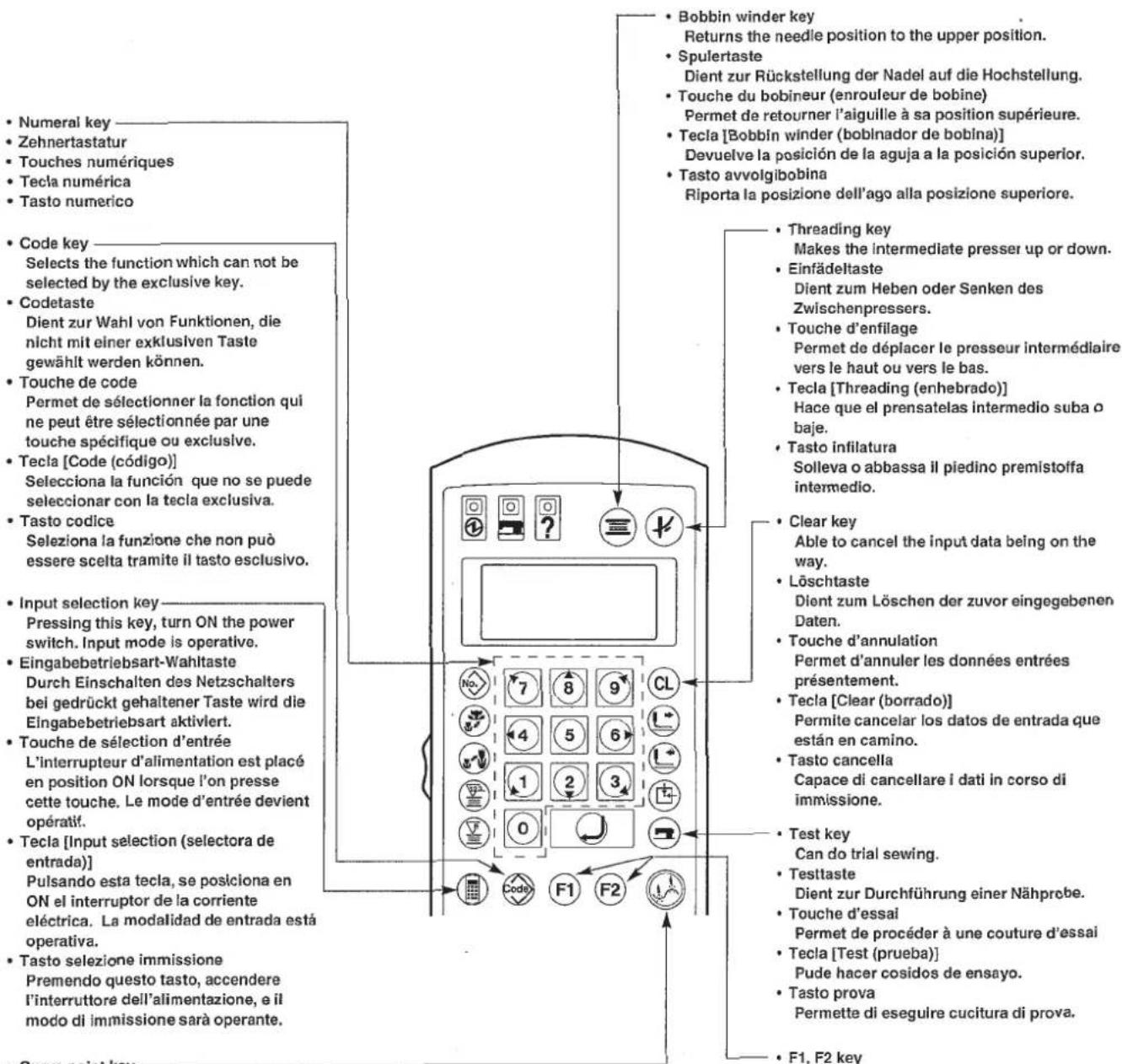
Indication of Pattern No.: Can be changed by No. key and Numerical key.
2,3 Enlargement / reduction indication : Indication of 1000 shows 100%.
· X(Y) - :100% fixed.
- X (Y) P : Enlargement / reduction can be made by increasing / decreasing the pitch.
X (Y) S : Enlargement / reduction can be made by increasing / decreasing the number of stitches.
Bobbin thread counter : Set by key and numerical key.
Production counter : By pressing 已 key, push 已 key to clear the counter to 0000.
To prevent possible accidents caused by the fall of the sewing machine, perform the work by two persons or more when the machine is moved.
WARNING :
1) Securely install control box 2, power switch 3 and pedal switch 4 on table (14222301) 1.
2) Connect the pedal with 4 the pedal switch using the chain 1.
3) Securely fix the respective power cables with the staples.
4) Securely fix oil drain 7 on the table 1, and screw oil receiver 8.
5) Set cushion rubber on oil pan, and fit oil pan to the holes of the table hinges (4 places). Then fix oil pan at 4 places with wood screws.
6) Close the center portion of oil pan ⑥ with the rubber plug after screwing it.
7) Strike head support bar in the hole of table 1.
8) Connect the pedal with manual pedal link A (machine head side) using chain supplied with the machine.
- For pneumatic type, it is not necessary to install 4 , 12 and 13 .
Power source specifications are indicated on the voltage indication seal.
Connect the cord in accordance with the specifications.
- Never use under the wrong voltage and phase.
- When changing the voltage to be used :
Refer to the item "Changing the voltage between 100 and 240V " for the following specifications.
10100V, 10110V, 10120V, 10200V, 10220V, 10230V, and 10240V
Refer to the item "Changing the voltage between 200 and 415V " for the following specifications.
30200V,30220V,30230V,30240V,30380V,30400V,and 30415V
(Attention)
100V,110V,120V,200V,220V,230V,e1240V
When the voltage of 100V or 200V is supplied, following voltages can be used by changing the terminal board.
When voltage of 100V, 110V or 120V is used, it is necessary to connect the voltage change cord (Part No. M90215800A0) to J32 connector mounted on the POWER circuit board.
When voltage of 200V, 220V, 230V or 240V is used, remove J32 connector.
If the setting of J32 connector is mistaken, the control box is likely to be broken.
Changing the voltage between 220V and 415V
When the voltage from 220V to 415V is supplied, following voltages can be used by changing the terminal board.
To prevent possible accidents caused by the fall of the sewing machine, perform the work by two persons or more when the machine is moved.
WARNING :
Fit hinge rubber to the hinge shaft, and fix the sewing machine main unit.
(Caution)
Hold section A when moving the sewing machine. In addition, donot hold motor portion B.
- Attaching the pedal chain (For solenoid type only)
Connect the manual pedal link 2 and manual pedal with chain 3.
Install motor cover 1 to the sewing machine main unit using the screws set in the cover.
Fix operation box attaching plate 1 on the table with woodscrew 2 and pass the cable through hole 3 in the table.
Remove vinyl coated on the surface of sheet.
(Caution) Either J19 or J20 of MAIN circuit board can be used for the pedal.
Remove the pedal which is not used since the machine may fail to work if both pedals are simultaneously connected.
Perform the connection of the cords as shown in the figure below.
Bund CN2 and CN7 together with other cords using clip band so that they do not come in contact with Y feed shaft A.
Pass the cords of J19, 20 through the cord clamp A and the cords of J14 through the cord clamp B located on the upper side of the inside of the control box.
After performing the connection of the cords, fix the cords under the table as shown in the figure.
(Caution) Connect the cords in a state that the sewing machine is tilted, bundle the cords with cable clip band, and fix them with cable clamp as shown in the figure.
For the pneumatic type, connect the air hose.
1) Cut the air tube supplied with the machine in an appropriate length, and connect solenoid valve 1 with air regulator 2.
2) Adjust the air pressure to 0.5 to 0.55MPa (5 to 5.5kgf/cm^2 ) by pulling up and turning knob 1 of the air regulator while observing air pressure gauge 4.
Turn knob 5 located in front of the air regulator using a small screwdriver and adjust the pressure switch to 0.4Mpa (4kgf/cm^2)
Be sure to attach this cover to protect the eyes from the disperse of needle breakage.
WARNING :
Be sure to install and use eye protection cover 1.
1) Assemble the thread stand, and set it in the hole in the top right corner of the machine table.
2) Tighten locknut to fix the thread stand.
3) When ceiling wiring is possible, pass the power cord through spool rest rod
(1) Den Garnständer zusammenbauen und in das Loch in der oberen rechten Ecke der Tischplatte einsetzen.
2) Die Gegenmutter 1 anziehen, so daß der Gamständer einwandfrei befestigt ist.
3) Wenn Deckenverkabelung möglich ist, kann das Netzkabel durch die Spulenhaltestange Ⓒ geführt werden.
1) Assembler le porte-bobines et le poser sur l'orifice du coin supérieur droit de la table.
2) Serrer le contre-écrou 1 pour fixer le porte-bobines.
3) Lorsqu'une alimentation électricque par le plafond est possible, faire passer le cordon d'alimentation dans la tige du porte-bobines 2.
1) Ensamble el pedestal de hilos, y fíjelo en el agujero en la esquina tope de la derecha de la mesa de laquina.
2) Apriete la contratuerca 1 para fjjar el pedestal de hilos
3) Cuando sea possible la instalacion del alambrado en el techo, pase el cable de alimentacion por la varilla en que descansa el carrete.
1) Montare il portafilo e insertiro nel foro nell'angolo in alto a destra del tavolo della macchina.
2) Stringere controdado per fissare il portafilo.
(3) Per il cabaggio ad una presa di alimentazione aerea far passare il cavo di alimentazioneattraverso l'asta portarocchetto 2.
(13) Attaching and removing the bolt for transportation Anbringen und Entfernen der Transportschraube Pose et retrait du boulon de transport Mode de poner y quitar el perno para el transporte Installazione e rimozione del bullone per trasporto
(When transporting the sewing machine)
When transporting the sewing machine, fix the sewing machine main unit and table with the bolt for transportation.
When operating the sewing machine, remove the bolt. If the machine is operated with the bolt fixed, vibration of the machine head is transmitted to the table. As a result, feed movement may be badly affected or the element inside the control box may be damaged.
1) Install the auxiliary throat plate cover support 2 to auxiliary throat plate cover 1 using setscrew 3 (L=6) and washer 4.
2) Install the cover on the machine arm using attaching screw ⑤ (L = 8)
(Caution)
Adjust so that the auxiliary throat plate cover should be almost levelled with the throat plate. If there is a difference in height, the feed plate may be caught with the auxiliary throat plate cover.
When tilting/raising the sewing machine head, perform the work so as not to allow your fingers to be caught in the machine. In addition, to avoid possible accidents caused by abrupt start of the machine, turn OFF the power to the machine before starting the work.
WARNING:
When tilting the sewing machine head, tilt the head gently until head support rod comes in contact with the head.
(Caution)
- Make sure that head support rod 0 is attached to the machine table before tilting the sewing machine head.
- When the sewing machine head is tilted, feeding frame ② moves to the left side by itself and interferes with the intermediate presser or the like. As a result, it will be the cause of breakage.
Remove the aforementioned component in advance, or fix feed plate to throat plate support cover with tape or the like, and tilt the sewing machine head.
- When tilting the sewing machine head while holding motor cover ⑤ and throat plate support cover ①, the covers may be bent. Be sure to tilt the sewing machine head while holding the main unit of the sewing machine.
- Be sure to tilt the sewing machine head on a flat place to prevent it from falling.
Turn OFF the power before starting the work so as to prevent accidents caused by abrupt start of the sewing machine. If you don't use the machine for a long time, lubricate it to protect against rust gathering.
When you restart up the machine after disuse for a long time, lubricate it to protect against seizure and abrasion.
WARNING:
(Caution) Be sure to perform the above 2) and 3) steps when the machine is first installed, or when it is run after a long period of disuse.
Loosen setscrew ① and hold needle ② with the long groove facing toward you. Then fully insert it into the hole in the needle bar, and tighten setscrew ①.
(Caution) If the stitches are made as shown in A, attach the needle facing to the direction 6 to a small extent.
Do not place your fingers or any thing under the presser since there is a danger of damage of your fingers or hands caused by being caught in the presser, needle, etc.
WARNING :

When passing thread through the needle, perform following operations to lower the intermediate presser and the feeding frame.
1) Press the key on the operation box.
2) After passing thread through the needle, press again the key and the intermediate presser and the feeding frame go up.
Pull out the thread by approximately 4cm from the needle after threading through the needle.
1) Open hook cover 0.
2) Raise latch 3 of bobbin case 2, and remove the bobbin case.
3) When installing the bobbin case, fully insert it into the shuttle shaft, and close the latch.
(Caution)
If it is not fully inserted, bobbin case ② may slip off during sewing.
1) Set the bobbin into bobbin case in the direction shown in the figure.
2) Pass the thread through thread slit 3 of bobbin case 4, and pull the thread as it is. By so doing, the thread will pass under the tension spring and be pulled out from thread hole 4.
3) Pass the thread through thread hole of the horn section, and pull out the thread by 2.5cm from the thread hole.
(Caution)
If the bobbin is installed in the bobbin case orienting the reverse direction, the bobbin thread pulling out will result in an inconsistent state.
If thread tension controller No. 1 is turned clockwise, the length of remaining thread on the needle after thread trimming will be shorter. If it is turned counterclockwise, the length will be longer.
Shorten the length to an extent that the thread is not slipped off.
Adjust the needle thread tension with 2 , and bobbin thread tension with 3 .
The standard stroke of thread take-up spring 1 is 6 to 8mm and the pressure at the start is 0.3 to 0.5N.
1) Adjusting the stroke Loosen setscrew 2, and turn thread tension asm. 3
2) Adjusting the pressure Insert a screwdriver into the slit of thread tension rod 4, and turn it.
3) When the stoke of thread take-up spring is changed, adjust the thread breakage detector plate referring to Page 64.
8. Adjusting the height of the intermediate presser /
1) Lower the intermediate presser. (Refer to "3. Threading the machine head".
When the intermediate presser is in the lowest position of its stroke, adjust so that the clearance between the intermediate presser and the cloth is approximately 0.5mm
2) Turn the handwheel to lower the needle to its lowest position.
3) Loosen setscrew 1 and adjust the height of intermediate presser 2.
1) Remove the machine arm side cover.
2) Loosen setscrew 1 and move it in the direction of arrow for adjustment.
3) If moving in the direction of A, the stroke will be decreased. (Min. 4 mm) If moving in the direction of B, the stroke will be increased. (Max. 10 mm)
(Caution)
The nut may be removed if setscrew is excessively loosened. So, be careful. Loosen setscrew by a half turn to properly adjust the stroke.
1) Remove the top cover.
2) Loosen two setscrews in the intermediate presser cam and slide the cam in the direction of B by 7 to 10mm . Then, tighten setscrews
3) When returning the cam to its home position again, loosen setscrews ① , slide the cam in the direction of C, strike the end face of the intermediate presser cam against the intermediate presser cam stopper, and align the engraved marker dots A. Then, tighten setscrews ① .
- Reading a sewing pattern data in the sewing machine /
Never place your fingers or any other thing under the feeding frame as the feeding frame automatically comes down after the completion of computing a pattern.
WARNING:
As an example, read a sewing pattern using a service pattern.
1) Turn ON the power switch.
2) Insert a floppy disk.
3)Push the key.
4) Input a pattern No. of three figure number pressing the numerical key. Input 5 0 0 in the service pattern.
5)Push the key.
When the pattern reading procedure completes, the feeding frame comes down once. Then the machine will retrieve the origin and the sewing LED ① will light up. Now, it is ready to start sewing.
- Make sure without fail of the contour of the sewing pattern after selection of the sewing pattern.
If the sewing pattern extends outside the work clamp feet, the needle will interfere with the work clamp feet during sewing, causing dangerous troubles including needle breakage. - When checking the sewing pattern, for the solenoid type, do not depress the pedal switch up to the second step, and for the pneumatic type, do not depress the start pedal. If doing so, the sewing machine starts sewing.
WARNING :
1) For the solenoid type, depress the pedal switch to the first step to descend the feeding frame.
For the pneumatic type, depress the presser pedal to descend the feeding frame.
2) Every press on the key or the key will move the needle point by one stitch. Keeping the key held pressed, the needle will move continuously.
3) After you have checked the contour of the sewing pattern, press the key. This will return the needle point to the start position and the feeding frame will go up.
If you keep pressing the key or the key for more than a certain time, the feed will continue even if you detach the key. Press the key again to stop the feed.
(Caution)
For the solenoid type, detach the foot from the pedal after one stitch is fed by the feed.
1) Set a workpiece on the work clamp foot section.
2) Depress the pedal switch to the first step, and the work clamp feet will come down. If you detach your foot from the pedal switch, the work clamp feet will go up.
3) Depress the pedal switch to the second step after descending the work clamp feet, and the sewing machine will start sewing.
4) After the sewing machine completes the sewing, the work clamp feet will return to the home place, and go up.
Magnetspulentyp
1) Set the sewing material to the portion of work clamp feet.
2) Depress the pedal A, and the right-hand work clamp foot will come down. If depressing the pedal again, the work clamp foot will go up.
3) Depress the pedal B, and the left-hand work clamp foot will come down. If depressing the pedal again, the work clamp foot will go up.
4) Depress the pedal C, and the sewing machine will start sewing.
5) After the sewing machine completes sewing, the work clamp feet will return to the home place, and go up.
(Note) When the 3-step PK pedal is used, start the start pedal shifting to the left direction.
1) Press the key. (the sewing LED will go off.)
2) Press the key.
3) Input the pattern number.
In case of the service pattern, input
4) Press the key. (the sewing LED will light up.)
Now, the sewing is ready.
For further steps, refer to "2. Checking the contour of a sewing pattern" (Refer to the previous page).
You can temporarily stop the sewing machine during sewing or sewing pattern shape checking procedure.
Press temporary stop switch 1 while the sewing machine is running. This will temporarily stop the sewing machine.
The sewing machine makes a revolution and the needle goes up and comes down. So, never place your fingers or any other thing under the needle.
WARNING :
1) As "Stopkey Accepted" is shown on the operation panel, press again the temporary stop switch and actuate the thread trimmer.
(It is not necessary to press the temporary stop switch again when the needle thread and needle are not tied together such as on the way of jump feed or the like, or when continuing the sewing as it is.)
(Caution)
If the main shaft is not in the upper resting position, ON/OFF the needle threading switch will first make the main shaft return to the upper resting position.
2) Pressing the key, key or key will make the needle point return to the initial position.
3) Press the pedal switch for re-starting. (Pedal switch for the pneumatic type is different from the figure on the left.)
1) Wenn "Stopkey Accepted" auf der Bedienungstafel angezeigt wird, die Pausentaste erneut drücken und den Fadenabschneider ausliesen. (Dieser Schritt erbrigt sich, wenn der Nadelfaden nicht mit dem Nahgut verknüpf ist, z.B. bei Sprungvorschub, oder wenn der Nähvorgang unverändert fortgesetzt wird.)
(Vorsicht) Falls sich die Hauptwelle nicht in der oberen Ruhestellung befindet, wird sie durch Ein- und Ausschalten des Nadeleinfadelschalters in die obere Ruhestellung gebracht.
2) Durch Drücken der Taste, oder wird die Nadelspitze auf die Ausgangsstellung zurückgeführnt.
3) Zum erneuten Starten des Nährvorgangs den Pedalschalter niederrücken. (Der Pedalschalter fur den Drucklufttyp ist anders als der in der linken Abbildung gezeigte.)
1) Lorsque "Stopkey Accepted" s'affiche sur le panneau de commande, appuyer à nouveau sur le bouton de pause et actionner le coupe-fil. (Il n'est pas nécessaire d'appuyer à nouveau sur le bouton de pause lorsque le fil d'aiguille n'est pas noué avec le tissu comme, par exemple, lors d'un entrainment sans couture ou pour continuer à coudre.)
(Attention) Si I'arbre principal ne se fouve pas sur la position de repos supérieure, appuyer sur I'interrupteur d'enfilage de I'aiguille pour I'y ramener.
2) Lorsqu'on appuie sur la touche (ou l'aiguille revient sur sa position initiale.
3) Pour reprendre la couture, appuyer sur la pédale. (La pédale pour le type pneumatique est différente de la pédale représentée sur la figure ci-contre.)
1) Como en el panel de operacion se visualiza "Stopkey Accepted" (se acaeta tecla de parada), pulse Nuevoamente el interruptor de parada temporal y actuará el cortahilo. (No es necessario pulsarNuevoamente el interruptor de parada temporal cuando el hilo de agua y la agua no está atados entre si como en el transporte de salto o casa semejante, o cuando se continua el cosido tal como está.)
(Precaún) Si el eje principal no descansa en la posicón superior, posicionando en ON/OFF el interruptor de enhebrado de aguja para que el eje principal returne primero a la posicón de descanso superior.
2) Pulsando la tecla, la tecla o la tecla la punta de la aguja vuelte a la posicjion inicial.
3) La reanudacion de la operacion de inicio se hace presionando el interruptor de pedal. (El interruptor de pedal para el tipo neumatico es differente del de la figura.)
1) Quando Stopkey Accepted "Tasto di Arresto Accettato" è molto su pannello operativo, premere nuovamente linteruttore di arrestotemporaneo e fare funzionare il rasafilo. (Non è necessario premere nuovamente linteruttore di arresto temporaneo quando il filo dellago e la stoffa non sono legati insieme come durante lo spostamento o cose simili, o quando si continua la cucitura così come.)
(Attenzione) Se la bilero principale non è nella posizione superiore, accendendo/spegnendo linterruttore di infilatura ago, prima di tutto la bilero principale sarea riportato alla posizione superiore.
2) Premendo il tasto 日 il tasto o il tasto, la punta dellago sare riportata alla posizione iniziale.
3) Riavvio puo assere fatto premendo lnterruttore a pedale. (lnterruttore a pedale per tipo pneumatico è differente alla figura.)
6. Winding the bobbin thread / Bewickeln einer Spule / Bobinage du fil de canette / Modo de bobinar una bobina / Avvolgimento del filo della bobina
6-1. To wind a bobbin while the sewing machine is performing sewing /
Thread the bobbin winder and wind the thread onto the bobbin as illustrated in the figure.
1) Set the bobbin as shown in the above figure.
2) Press () , and depress the start switch. Then, the bobbin winder will start to wind the bobbin.
3) The bobbin winder can be stopped by taking one of the following three procedures.
Press the bobbin winder switch.
Press the start switch again.
Press the temporary stop switch.
(Note)
Pedal switch for the pneumatic type is different from the figure on the left.
Turn OFF the power before starting the work so as to prevent accidents caused by abrupt start of the sewing machine.
WARNING:
In case a same sewing pattern is sewn in repetition, the sewing machine will stop sewing when the number of workpieces (the specified number of workpieces) that can be sewn with a bobbin is reached. The bobbin thread counter indicates the finished number of workpieces in the two different methods. You can select either the adding method or the subtracting method. (Adding method is provided at the time of delivert.) (Refer to "VIII. How to use the memory switch"(Page 67))
1) Press the key.
Press the numerical key, and input the specified number of workpieces that can be sewn with a bobbin.
2) Insert a floppy disk into the floppy disk inserting slot. Input a sewing pattern No. desired and press the key.
3) Every time the sewing machine finishes a workpiece, counting is made by one.
4) When the sewing machine finishes the specified number of workpieces, the sewing machine will stop.
5) Replace the bobbin with a new one, and press the key.
6) Repeat the steps of procedure from step 3).
- Performing sewing by means of "Pattern enlarging / reducing function"
Sewing can be performed by enlarging/reducing the sewing pattern. Enlarging/reducing can be selected from two kinds of "number of stitches increasing/reducing" and "stitches length increasing/reducing". This function can be set by the memory switch (P.67 and following pages). The memory switch is set to "number of stitches increasing/reducing" at the time of delivery.
1) Insert a floppy disk into the floppy disk inserting slot and input a sewing pattern No. desired.
2) Input a scale (%) by which the sewing pattern is to be enlarged / reduced in the X or Y direction.
(Caution)
The pattern can be enlarged / reduced in the range of 1% to 400% while the size of pattern written in the floppy disk is taken as 100% .
3) Press the key, and the specified size of the sewing pattern will be read in the sewing machine. Then, the machine will be ready for sewing.
(Caution)
- After the pattern is enlarged or reduced, make sure the movement whether the needle and the feeding frame interferes with each other.
- The method of enlarging / reducing is "number of stitches increasing / reducing" under the state of delivery of the memory switch.
- If a workpiece cannot be set on the sewing machine because of the interruption by the needle point /
Normally, the feeding frame rests at the sewing start position when you set a workpiece to be sewn on the sewing machine. If you cannot easily place the workpiece on the machine since the needle point interferes with you, you can specify the position of the feeding frame as desired. (The sewing position will remain the same.)
1) Insert a floppy disk into the slot and input a sewing pattern No. desired.
2) Press the key, and the sewing machine will read the sewing pattern data from the floppy disk and the feeding frame will go up at the start position of sewing.
3) Depress the pedal to make the feeding frame come down. Then, press the direction key and the needle point will move.
4) After you have moved the needle to a position at which the needle point does not interfere with the workpiece to be set, press the key or depress again the pedal.
(Caution)
- If the key is pressed twice continuously, the turnout point specified will be cancelled.
- If you specify a new turn-out point, the previously specified one will be cancelled.
After turning the power switch ON, slowly insert the floppy disk, with its face A looking to the upper as observed from you, until the eject button pops out.
2) Unloading the floppy disk
After the reading of the floppy disk is over, press the eject button and take out the floppy disk.
3) Write-protect hole
When the write-protect tab is moved to open the write-protect hole, no data is allowed to be written into the disk. Use for retaining the programmed data.
For writing data into the disk, move the write-protect tab until it is exposed.
(Caution) Never turn the power switch ON or OFF with the floppy disk mounted.
Do not place the floppy disk near an ashtray or food and drink.
Do not bring the floppy disk close to a magnetized material.
Do not touch the exposed parts of the floppy disk.
Do not place the floppy disk in a hot place (51°C or higher) or a place exposed to direct sunlight.
Reference for the sewing speed to be applied
| Sewing speed (sti/min) | |
| Denim 8 pcs. | 2,200 to 2,500 |
| Denim 12 pcs. | 2,200 to 2,500 |
| Clothes | 2,200 to 2,500 |
| Clothes (Synthetic thread used) | 2,000 to 2,300 |
| Knit | 1,800 to 2,000 |
| Foundation | 1,800 to 2,000 |
※ To prevent the thread breakage due to the needle heat, set the sewing speed referring to the above table in accordance with the sewing conditions.
※ For sewing the foundation or the like, lower the height of the needle bar to prevent the stitch skipping. (Refer to the height of the needle bar (P.57).)
Bring needle bar 1 to the lowest position of its stroke. Loosen needle bar connection screw 2 and adjust so that upper marker line 4 engraved on the needle bar aligns with the bottom end of needle bar bushing, lower 3.
(Caution) After the adjustment, make sure that there is no uneven torque.
※ When stitch skipping occurs in accordance with the sewing conditions, adjust the height of the needle bar so as to lower it by 0.5 to 1 mm from the needle bar engraved line
Turn OFF the power before starting the work so as to prevent accidents caused by abrupt start of the sewing machine.
WARNING:
1) Loosen setscrews 2 located on the right- and left-hand sides of feed bracket 1. Move cloth presser stopper 3 in the direction of B to increase the height.
2) After adjusting the height, securely tighten setscrews ②.
Magnetspulentyp
1) Loosen setscrew in feed bracket and move cloth presser hook in the direction of B to increase the height.
2) After adjusting the height, securely tungten setscrew ②.
Drucklufttyp
4. Adjusting the rising amount of the thread tension disk /
Turn OFF the power before starting the work so as to prevent accidents caused by abrupt start of the sewing machine.
WARNING :
1) Remove the top cover. Make sure that tension release pin ③ rides on tension release notch ④.
2) If the pin does not ride on the notch, push cam follower by hand to the direction, and rotate the main shaft in the correct direction to make a state as illustrated in the figure.
3) Under the state as illustrated in the figure, loosen setscrew 2 in the tension release adjusting arm. By moving tension release adjusting arm 1 to the left or right the rising amount of the thread tension disk will change.
S type: 0.6 to 0.8mm
H type: 0.8 to 1.0 mm
(Caution)
If the rising amount is insufficient, the length of the remaining thread after thread trimming will be not stable. If the rising amount is excessive, after releasing the rising of the thread tension disk, the disk closing will be defective.
Turn OFF the power before starting the work so as to prevent accidents caused by abrupt start of the sewing machine.
WARNING :
Turn OFF the power before starting the work so as to prevent accidents caused by abrupt start of the sewing machine.
WARNING :
1) Adjust so that thread breakage detector plate 1 is always in contact with thread take-up spring 2 in the absence of needle thread. (Slack : approx. 0.5mm )
2) Whenever the stroke of thread take-up spring 2 has been changed, be sure to readjust thread breakage detector plate 1. To make this adjustment, loosen screw 3.
(Caution)
Adjust so that thread breakage detector plate 1 does not touch any adjacent metallic parts other than thread take-up spring 2.
Clean filter 2 of the control box fan once every week.
1) Pull screen kit 1 in the direction of arrow to remove it.
2) Wash filter 2 under running water.
3) Reinstall filter 2 and screen kit 1.
When polyethylene oiler becomes filled with oil, remove polyethylene oiler and drain the oil.
- To avoid electrical shock hazards, turn OFF the power and open the control box cover after about five minutes have passed.
- Open the control box cover after turning OFF the power without fail. Then, replace with a new fuse with the specified capacity.
WARNING :
The machine uses the following 4 fuses :
1,2 For servo motor power supply protection 10A each (standard melting fuse)
For solenoid power supply protection 10A (time-leg fuse)
For stepping motor (X and Y) protection 8 A (standard melting fuse)
Pressing 5 of the numeral key, turn ON the power switch. Then, the indication by memory switch will appear and the sewing machine movements can be changed.
(1) Setting the bobbin thread counter indication
Change the bobbin thread counter from adding method to subtracting method, and the production counter from ON to OFF.
1) Pressing key, display "009 COUNTER" using ⑤ ② key. Initial condition is as follows :
Bobbin thread counter : Adding method Production counter : ON
2) Pressing key, press key. Every time you press key, the indication will change "UP" to "DOWN". Put "DOWN" on the display and press the key.
Now, the adding method has been changed to the subtracting method.
3) Pressing key, press 2 key. Every time you press 8 key, the indication will change "ON" to "OFF". Put "OFF" on the display and press the key. Now, the production counter has been changed to OFF.
BOBBIN UP PRODUCT ON
009.COUNTER
BOBBIN DOWN PRODUCT ON
009.COUNTER
BOBBIN DOWN PRODUCT QEE
009.COUNTER
BOBBIN UP PRODUCT ON
009.COUNTER
BOBBIN DOWN PRODUCT ON
009.COUNTER
BOBBIN DOWN PRODUCT OFF
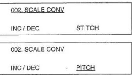
(2) Setting enlarging / reducing function
The function of enlrging / reducing can be changed from increasing / decreasing number of stitches to increasing / decreasing sewing pitch.
1) Pressing the key, display "002 SCALE CONV" using 6 key. Initial condition is of increasing / decreasing number of stitches.
2) Pressing key, press 5 2 key. Every time you press 8 2 key, the indication will change in the order of "STITCH" 6 2 "PITCH" 8 2 "PROHIBIT" 8 2 "STITCH". Put "PITCH" on the display and press the key. Now, the enlarging / reducing function is of increasing / decreasing the sewing pitch.
| Function No. | Contents of function | ① |
| Contents of Item 1 | - Contents of setting Item 1 | ② |
| Contents of Item 2 | - Contents of setting Item 2 | ③ |
| Contents of Item 3 | - Contents of setting Item 3 | ④ |
Setting procedures of changing the respective items.
① Function No.
Change the key using 3 key.
② Contents of setting Item 1
Change the key using key.
③ Contents of setting item 2
Change the key using 3 key.
④ Contents of setting Item 3
Change the key using
The respective items will be decided by the key after being set by the key.
- Setting value in is the initial setting value.
Table of functions of the memory switch
| No. | Function | Item | Setting value | Description |
| 002 | SCALE CONV | INC / DEC | [STITCH]/PITCH / OFF | Under enlargement / reduction mode, data setting is fixed as stitch / pitch / 100%. |
| 003 | JOG MODE | MODE | PARA /2ND/OFF | This mode sets the movement of sewing position or turn-out position. |
| 008 | ON ABORT | MODE | [ROUTE]/HOME &/TRACE | This selects the route of origin retrieval. |
| AUDET | [OFF]/ON | Origin retrieval: When the machine retrieves, this sets if the needle should be raised to the highest position. | ||
| 009 | COUNTER | BOBBIN | UP / DOWN | This changes UP / DOWN of the bobbin thread counter. |
| PRODUCT | [ON]/OFF | This sets ON / OFF of the production counter. | ||
| 013 | STOP SW | TRIM | [STOP]/AUTO / NDL | This sets the thread trimmer switch after temporary stop. |
| 023 | FUNC KEY | F1 | -1- (INITIAL STAGE : 2nd origin) | This will select the function of F1 key. |
| F2 | -1- (INITIAL STAGE : INPUT ARC) | This will select the function of F2 key. | ||
| 027 | NDL UP DTCT | POSITION | [UDET]/AUDET | This sets the stopping position of the needle bar. |
| 029 | MOTOR SYNC | PCH-SPD | 0 TO 3 (INITIAL STAGE : 0) | 0:2,500 stl/min / 3 mm1:2,000 stl/min / 3 mm2:1,700 stl/min / 3 mm3:1,300 stl/min / 3 mm |
| PAUSE | -4 TO 9 (INITIAL STAGE : 0) | Every time you increase by one, you can advance the feed end of X/Y scale by 8'. | ||
| 030 | OUTER PRSR 1 | PEDAL | [0]/1/2/3 | Opening or closing of the feeding frame can be controlled by operating the pedal. |
| PAUSE | [0]/1/2/3 | Opening or closing of the feeding frame after temporary stop can be controlled by operating the pedal. | ||
| 031 | OUTER PRSR 2 | RELEASE | [ATSTART]/HOLD / ATEND | This selects the way of lifting the feeding frame after the sewing is finished. |
| HOLDING | OFF /[ON] | This keeps the feeding frame held lowered. | ||
| 032 | PEDAL MODE 1 | PEDAL 1 | LATCH /FLIP | The feeding frame can be lowered while the pedal 1 is held depressed. (Air type: LATCH) |
| PEDAL 2 | [LATCH]/FLIP | The feeding frame can be lowered while the pedal 2 is held depressed. | ||
| PEDAL 3 | [LATCH]/FLIP | The feeding frame can be lowered while the pedal 3 is held depressed. | ||
| 033 | PEDAL MODE 2 | PEDAL 4 | [LATCH]/FLIP | The feeding frame can be lowered while the pedal 4 is held depressed. |
| 035 | I. PRSR | SWITCH | OFF /[SEW]/ TRIAL | The movement of the intermediate presser can be prohibited. |
| DOWN AT | O.PRSR / START | The timing of the movement of the intermediate presser can be coordinated with the feeding frame. | ||
| 038 | T.BRK DTCT | SWITCH | [ON]/OFF | This sets ON / OFF of the thread breakage detector. |
| 039 | AIR PRSR | SWITCH | ON / [OFF] | This sets if the air pressure is checked. |
| 050 | MTR SPEED 1 | SPEED 1 | 2 | Sets speed of 1st stitch at the start of sewing. |
| SPEED 2 | 6 | Sets speed of 2nd stitch at the start of sewing. | ||
| SPEED 3 | 10 | Sets speed of 3rd stitch at the start of sewing. | ||
| 051 | MTR SPEED 2 | SPEED 4 | 25 | Sets speed of 4th stitch at the start of sewing. |
| SPEED 5 | 25 | Sets speed of 5th stitch at the start of sewing. | ||
| 098 | PEDAL MODE 3 | PEDAL 1 | LOW / HIGH | This selects the pedal 1 active. |
| PEDAL 2 | LOW / HIGH | This selects the pedal 2 active. | ||
| PEDAL 3 | LOW / HIGH | This selects the pedal 3 active. | ||
| 099 | PEDAL MODE 4 | PEDAL 4 | LOW / HIGH | This selects the pedal 4 active. |
| LOW / HIGH | This selects the start pedal active. | |||
| 112 | TENSION DISK | SWITCH | ON /OFF | Set ON when optional solenoid for thread tension disk rise is used. |
1. Names of the switches for input mode
- Bedienungselemente für die Eingabebetriebsart
- Désignation des interrupteurs/touches pour le mode d'entrée
- Nombres de los interruptores para modalidad de entrada
- Nomi degli interruttori per il modo di immissione
- Curve point key
Can store the point on a curve.
(Note) Use end point key for input of an arc and a circle.
The foment you desire can be stored exclusively.
2. Operation of input mode
Input mode starts when pressing the key, the power switch is turned ON. (Display ①)
A:Shows the origin.
(2) Selecting the function
Way of selecting the function is as follows :
1) Selection by the exclusive key Selection by the exclusive key on the operation panel.
2) Selection from the function No. Specify by 念 key Numeral key and select by key. Refer the function No. to the separate table.
3)Selection from the table of functions Selection is made in the following order: 念 key 念 key indication scroll by 8 key 念 key. Display ② will be shown while the selection of function is being executed.
Display ②
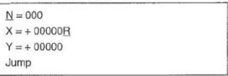
N: Point stored
R : Shows the point of sewing start
After input is finished, display ② will appear by means of key.
P = 020 (0.1 mm)
W = 010 (0.1 mm)
S = 1 (1:L,2:R)
Input P No 034
Display ③
P:Stitch length
W: Off-set, zigzag width
S : Direction of off-set
(3) Zifferneingabe
When using a new disk, be sure to initialize it to make it adaptable to a device.
1) Pressing the key, turn ON the power switch. The mode enters to the input mode.
(Caution) Keep the key held pressed until the indication appears after the origin retrieval has been performed.
2) Press the key.
3) Press the numeral keys and, then press the key. Format function No. = 090
4) Press the key.
5) Press the numeral key in case of 2HD disk, and the numeral key in case of 2DD disk. Then, press the key.
6) After inserting the floppy disk, press the key. The machine starts to format. It takes about four minutes.
After the formatting has been completed, the indication will return to the item 1).
Origin > X = +00000A Y = +00000 Select Function
No = 000 Select Function
No = 090 FD Formatting
K=1(1:1.44M(2HD)2:720K(2DD))
Kind of FD No 090
Sure (Y/C)
Formatting
$$ K = 1 (1: 1. 4 4 M (2 H D) $$
2:720K (2DD)
Kind of FD
No 090
Sure (Y/C)
Formatting
$$ X = + 0 0 0 0 0 A $$
$$ Y = + 0 0 0 0 0 $$
Select Function
$$ \mathrm {N o} = 0 0 0 $$
Select Function
$$ \mathrm {N o} = 0 9 0 $$
FD Formatting
$$ K = 1 (1: 1. 4 4 M (2 H D) $$
2:720K (2DD))
Kind of FD
No 090
Sure (Y/C)
Formatting
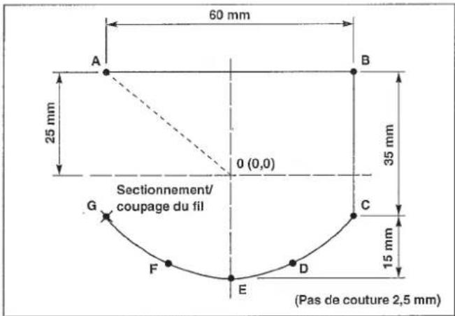
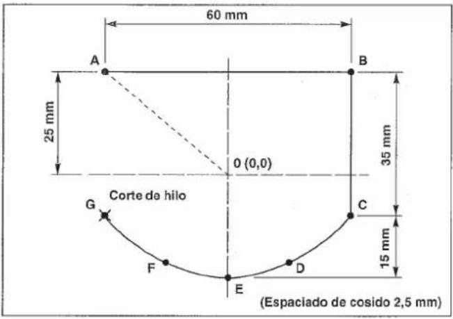
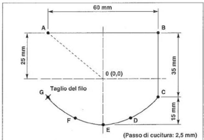
- Example 2 of pattern input
- Beispiel 2 der Mustereingabe
- Exemple 2 concernant I'entrée de configuration
- Ejemplo 2 de entrada de patrón
- Esempio 2 di immissione modello
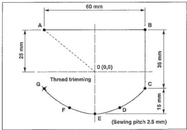
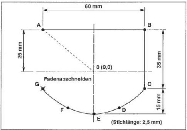
The procedures of the pattern described on the left are shown as follows:
(1) Pattern input
(2) Trial sewing
(3) Writing into a floppy disk
(1) Pattern input
1) Pressing the key, turn ON the power switch. The feeding frame comes down and the origin retrieval performance is made.
(Note) Keep the key held pressed until the origin retrieval performance is made and the display appears.
When the display appeared, insert a piece of paper or the like on which the shape of input is drawn by raising / lowering the feeding frame by means of the feeding frame switch.
2) Press the key.
3) Move the feeding frame from 0 to A by the direction key. (Amount of movement is indicated by 0.1mm unit.)
4) When the key is pressed, the feeding frame will return to the starting point "0", and the jump feed from 0 to A will be performed.
5) Press the key
6) As the pitch is set 2.5 ~mm , input 0 2 5 by the numeral key, and press the key.
7) Move the feeding frame from A to B by the direction key, and press the 1 key. Line sewing input can input the line and the curve. Input of the end point of the line or the curve is made by pressing the 1 key and input of a point on the curve is made by pressing the 1 key.
$$ \begin{array}{l} \text {O r i g i n} \quad - > > \ \mathrm {X} = + 0 0 0 0 0 \mathrm {A} \ Y = + 0 0 0 0 0 \ \text {S e l e c t} \ \end{array} $$
$$ \begin{array}{l} N = 0 0 0 \ X = + 0 0 0 0 0 R \ Y = + 0 0 0 0 0 \ J u m p \ \end{array} $$
$$ \begin{array}{l} N = 0 0 0 \ X = - 0 0 3 0 0 R \ Y = + 0 0 2 5 0 \ J u m p \ \end{array} $$
$$ \begin{array}{l} J u m p \quad > > > \ X = - 0 0 3 0 0 A \ Y = + 0 0 2 5 0 \ \text {S e l e c t} \ \end{array} $$
$$ \begin{array}{l} P = 0 2 0 (0. 1 \mathrm {m m}) \ \text {I n p u t} \mathrm {P} \quad \text {N o} 0 2 2 \ \end{array} $$
$$ \begin{array}{l} N = 0 0 0 \ \mathrm {X} = + 0 0 0 0 0 \mathrm {R} \quad \mathrm {P} = 0 2 5 \ Y = + 0 0 0 0 0 \ S e w i n g \ \end{array} $$
$$ \begin{array}{l} N = 0 0 1 \ \mathrm {X} = + 0 0 6 0 0 \mathrm {R} \quad \mathrm {P} = 0 2 5 \ Y = + 0 0 0 0 0 \ S e w i n g \ \end{array} $$
8) Move the feeding frame from B to C by the direction key, and press the key.
9) Move the feeding frame from C to D by the direction key, and input by the key.
10) Move the feeding frame from D to E by the direction key, and input by the key.
11) Move the feeding frame from E to F by the direction key, and input by the key.
12) Move the feeding frame from F to G by the direction key, and input by the key.
13)Press the key, and the line sewing is finished. The feeding frame returns to A point and passes A B C D E F G.
14) Press the key, and input the thread trimming.
Input procedures end as above.
Shape of input can be confirmed by the / key.
$$ \begin{array}{l} N = 0 0 2 \ \mathrm {X} = + 0 0 6 0 0 \mathrm {R} \quad \mathrm {P} = 0 2 5 \ Y = - 0 0 3 5 0 \ S e w i n g \ \end{array} $$
$$ \begin{array}{l} N = 0 0 3 \ \mathrm {X} = + 0 0 5 0 0 \mathrm {R} \quad \mathrm {P} = 0 2 5 \ Y = - 0 0 4 5 0 \ \mathrm {S e w i n g} \ \end{array} $$
$$ \begin{array}{l} N = 0 0 4 \ X = + 0 0 3 0 0 R \quad P = 0 2 5 \ Y = - 0 0 5 0 0 \ \mathrm {S e w i n g} \ \end{array} $$
$$ \begin{array}{l} N = 0 0 5 \ \mathrm {X} = + 0 0 2 0 0 \mathrm {R} \quad \mathrm {P} = 0 2 5 \ Y = - 0 0 4 5 0 \ \mathrm {S e w i n g} \ \end{array} $$
$$ \begin{array}{l} N = 0 0 6 \ X = + 0 0 0 0 0 R \quad P = 0 2 5 \ Y = - 0 0 3 5 0 \ \mathrm {S e w i n g} \ \end{array} $$
$$ \begin{array}{l} S p l i n e \ X = - 0 0 3 0 0 A \quad P = 0 2 5 \ Y = - 0 0 1 0 0 \quad S = * * \ \text {S e l e c t F u n c t i o n} \ \end{array} $$
$$ \begin{array}{l} \text {T h r e a d T r i m m e r} \ X = - 0 0 3 0 0 A \quad P = 0 2 5 \ Y = - 0 0 1 0 0 \quad S = * * \ \text {S e l e c t} \ \end{array} $$
N=004
X = +00300R P=025
Y = -00500
Sewing
N=005
X = + 00200R P=025
Y = -00450
Sewing
N=006
X=+00000R P=025
Y=-00350
Sewing
Spline ->>
X = -00300A P = 025
Y = -00100 S = ** Select Function
Thread Trimmer
->>
X=-00300A P=025
Y=-00100 S=*
Select Function
N = 002
X = +00600R P = 025
Y = -00350
Sewing
N = 003
X = +00500R P = 025
Y = -00450
Sewing
N=004
X = +00300R P=025
Y = -00500
Sewing
N=005
X = + 00200R P=025
Y = -00450
Sewing
N = 006
X = +00000R P = 025
Y = -00350
Sewing
Spline ->>
X = -00300A P = 025
Y = -00100 S = Select Function
Thread Trimmer X = -00300A P = 025
Y = -00100
S =
Select Function
$$ \begin{array}{l} N = 0 0 2 \ P = 0 2 5 \ Y = - 0 0 3 5 0 \ S e w i n g \ \end{array} $$
$$ \begin{array}{l} N = 0 0 3 \ X = + 0 0 5 0 0 R \quad P = 0 2 5 \ Y = - 0 0 4 5 0 \ \mathrm {S e w i n g} \ \end{array} $$
$$ \begin{array}{l} N = 0 0 4 \ X = + 0 0 3 0 0 R \quad P = 0 2 5 \ Y = - 0 0 5 0 0 \ \end{array} $$
$$ \mathrm {S e w i n g} $$
$$ \begin{array}{l} N = 0 0 5 \ \mathrm {X} = + 0 0 2 0 0 \mathrm {R} \quad \mathrm {P} = 0 2 5 \ Y = - 0 0 4 5 0 \ \mathrm {S e w i n g} \ \end{array} $$
$$ \begin{array}{l} N = 0 0 6 \ \mathrm {X} = + 0 0 0 0 0 \mathrm {R} \quad \mathrm {P} = 0 2 5 \ Y = - 0 0 3 5 0 \ \mathrm {S e w i n g} \ \end{array} $$
$$ \begin{array}{l} \begin{array}{c} \text {S p l i n e} \end{array} \ - > > \ X = - 0 0 3 0 0 A \ P = 0 2 5 \ Y = - 0 0 1 0 0 \ S = * * \ \text {S e l e c t} \ \end{array} $$
$$ \begin{array}{l} \text {T h r e a d T r i m m e r} \quad - > > \ X = - 0 0 3 0 0 A \quad P = 0 2 5 \ Y = - 0 0 1 0 0 \quad S = * * \ \text {S e l e c t} \ \end{array} $$
The feeding frame moves to A point and goes up.
No=001
JOG MODE
XS=1000
YS=1000
2) Sewing in the order of the normal sewing can be performed.
3) Press the key after confirming the completion of sewing.
The feeding frame comes down and stops at the origin after the origin retrieval.
Jump
S=***
X = 00000R
Y=00000
S=***
Select Function
Under this condition, the feeding frame can be moved by the 1 / 1 key, and the amendment of pattern can be made.
(2) Nähprobe
m = 311
YS=1000
$$ X = 0 0 0 0 0 R $$
$$ Y = 0 0 0 0 0 $$
$$ \text {S e l e c t} $$
$$ S = * * $$
① Writing into the the floppy disk
1) Press the key.
2) Specify the pattern No. desired by means of the numeral key.
3) By pressing the key, writing into a floppy disk can be performed.
4) If the pattern No. specified is already used, the dispaly will appear as shown in the figure on the right. In this case, indicate if the previous data should be cancelled.
key
Writing over
(delete the previous data)
@key
Cancellation
5) After the writing is finished, the display will be back to the previous condition.
(3) Schreiben
(borra el dato anterior)
Tecla C
Cancelacion
② Writing into the EEP-ROM
1) Press the key.
2) Specify "089" and press key.
3) Press key, and specify the pattern No. (2 figures) to write into the ROM by means of the numeral key.
4) By pressing the key, writing into the ROM can be performed.
5) If the pattern No. specified is already used, the display will appear as shown in the figure on the right. In this case, indicate if the previous data should be cancelled. After the writing is finished, the display will be back to the previous condition.
② Schreiben in EEP-ROM
1) Taste drucken.
N=000 Select Function
No = 089
Input Wrt No 089
No = 01 Input Wrt No 089
No = 01 Writing Pattern
No = 01 Over Write (Y/C)
N=000 Select Function
No = 089
Input Wrt No 089
No = 01
Input Wrt No 089
No = 01 Writing Pattern
No = 01 Over Write (Y/C)
N=000 Select Function
No = 089
Input Wrt No 089
No = 01 Input Wrt No 089
No = 01 Writing Pattern
No = 01 Over Write (Y/C)
N=000 Select Function
No = 089
Input Wrt No 089
No = 01
Input Wrt No 089
No = 01 Writing Pattern
No = 01 Over Write (Y/C)
When the needle point is at the sewing start, it may interfere with setting the material. In this case, input the second origin as shown in the figure.
1) Pressing the key, turn ON the power switch.
The feeding frame comes down, and origin retrieval performance is made.
(Note) Keep the key held pressed until the display appears after the origin retrieval.
When the display appeared, insert a piece of paper or the like on which the shape of input is written under the feeding frame by lowering or raising the feeding frame.
2) Press the key.
3) Move the feeding frame to 0^ by the direction key.
4) Press the key.
5) Press the F1 key.
(Note) In the _1 key "Second origin" is input as the initial condition.
6) Press the key.
7) Move the feeding frame from 0' to A by the direction key.
$$ \begin{array}{l} \text {O r i g i n} \quad - > > \ \mathrm {X} = + 0 0 0 0 0 \mathrm {A} \ Y = + 0 0 0 0 0 \ \text {S e l e c t} \ \end{array} $$
$$ \begin{array}{l} N = 0 0 0 \ \mathrm {X} = + 0 0 0 0 0 \mathrm {R} \ Y = + 0 0 0 0 0 \ J u m p \ N = 0 0 0 \ X = - 0 0 3 0 0 R \ Y = + 0 0 2 5 0 \ J u m p \ \end{array} $$
$$ \begin{array}{l} J u m p \quad > > > \ X = - 0 0 3 0 0 A \ Y = + 0 0 2 5 0 \quad S = * * \ \text {S e l e c t} \ \end{array} $$
$$ \begin{array}{l} \mathrm {S e c} - \mathrm {O r i g i n} \ X = - 0 0 3 0 0 A \ Y = + 0 0 2 5 0 \ \text {S e l e c t} \ \end{array} $$
$$ \begin{array}{l} N = 0 0 0 \ X = + 0 0 0 0 0 R \ Y = + 0 0 0 0 0 \ J u m p \ \end{array} $$
$$ \begin{array}{l} N = 0 0 0 \ \mathrm {X} = + 0 0 2 0 0 \mathrm {R} \ Y = - 0 0 1 5 0 \ J u m p \ \end{array} $$
8) Press the key.
9) Press the key.
10) As the stitch length is set 1.8 mm , input 0 , 1 , 6 by the numeral key, and press the key.
11) Move the feeding frame from A to B by the direction key, and press the key.
12) Move the feeding frame from B to C by the direction key, and press the key.
13) Move the feeding frame from C to D by the direction key, and press the key.
14) Press the key.
15) For D-E-F arc input is made. In this case, however, selection of function is made from the indication of the table of functions of the memory switch. Press the key.
16) Press the key or the key.
17) Select the arc input by 8 key.
18) Press the key.
Jump
X = +00100A
Y = -00100 S = *
Select Function
P = 020 (0.1 mm)
Input P
N=000
X = + 00000R P=018
Y = + 00000
Sewing
N = 001
X = + 00200R P = 018
Y = + 00000
Sewing
N=002
X = + 00200R P = 018
Y = - 00200R
Sewing
N=003 X = +00000R P=018
Y=-00200
Sewing
Linear
X = -00100A P = 018
Y = -00100 S = *
Select Function
No = 000 Select Function
001 = Thread Trim
002 = Sec - Origin
003 = Temp Stop
004 = Refer Point
025 = Arc Sewing
026 = Circle Sewing
030 = Linear Zig
031 = Spline Zig
P = 018 (0.1 mm)
Input P No 025
19) As the stitch length is set 1.8mm as before, press the key.
20) Move the feeding frame from D to E by the direction key, and press the key.
21) Move the feeding frame from E to F by the direction key, and press the key.
22) Press the key.
23) Press the key.
| N = 000 | |
| X = +00000R | P = 018 |
| Y = +00000 | |
| Arc |
| N = 001 | |
| X = -00100R | P = 018 |
| Y = + 00100 | |
| Arc |
| N = 002 | |
| X = +00000R | P = 018 |
| Y = +00200 | |
| Arc |
| Arc | |
| X = -00100A | P = 018 |
| Y = + 00100 | S = * * |
| Select Function |
| Thread Trimr |
| X = -00100A |
| Y = + 00100 |
| Select Function |
The input procedures now have been completed.
The shape of input can be confirmed by the 心 / 心 key.
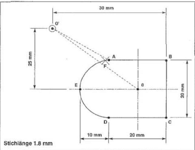
$$ \begin{array}{l} N = 0 0 0 \ X = - 0 0 3 0 0 R \ Y = + 0 0 2 5 0 \ J u m p \ \end{array} $$
$$ \begin{array}{l} J u m p \quad > > > \ X = - 0 0 3 0 0 A \ Y = + 0 0 2 5 0 \quad S = * * \ \text {S e l e c t} \ \end{array} $$
$$ \begin{array}{l} \mathrm {S e c} - \mathrm {O r i g i n} \ X = - 0 0 3 0 0 A \ Y = + 0 0 2 5 0 \ \text {S e l e c t} \ \end{array} $$
$$ \begin{array}{l} N = 0 0 0 \ \mathrm {X} = + 0 0 0 0 0 \mathrm {R} \ Y = + 0 0 0 0 0 \ J u m p \ \end{array} $$
$$ \begin{array}{l} N = 0 0 0 \ X = + 0 0 2 0 0 R \ Y = - 0 0 1 5 0 \ J u m p \ \end{array} $$
Jump
X = +00100A
Y = -00100 S = **
Select Function
P=020(0.1mm)
Input P
N = 000
X = + 00000R P = 018
Y = + 00000
Sewing
N = 001
X = + 00200R P = 018
Y = + 00000
Sewing
N=002
X = +00200R P=018
Y = -00200R
Sewing
N=003
X = +00000R P=018
Y = -00200
Sewing
Linear
X = -00100A P = 018
Y = -00100 S = * *
Select Function
No = 000 Select Function
001 = Thread Trim
002 = Sec - Origin
003 = Temp Stop
004 = Refer Point
025 = Arc
026 = Circle
030 = Linear
031 = Spline
P = 018 (0.1 mm)
Input P No 025
N = 000
X = +00000R P = 018
Y = +00000
Arc
| N = 002 | |
| X = + 00000R | P = 018 |
| Y = + 00200 | |
| Arc |
| Arc | |
| X=-00100A | P=018 |
| Y=+00100 | S=* * |
| Select Function |
| Thread Trim |
| X = -00100A |
| Y = + 00100 |
| Select Function |
P=020(0.1mm) Input P
N=000
X = + 00000R P=018
Y = + 00000
Sewing
N=001
X = + 00200R P=018
Y = + 00000
Sewing
N=002
X = +00200R P=018
Y = -00200R
Sewing
N=003
X = +00000R P=018
Y = -00200
Sewing
Linear
X = -00100A P = 018
Y = -00100 S = * *
Select Function
No = 000 Select Function
001 = Thread Trimr
002 = Sec - Origin
003 = Temp Stop
004 = Refer Point
025 = Arc Sewing
026 = Circle Sewing
030 = Linear Zig
031 = Spline Zig
P=018(0.1mm) Input P No 025
N=000
X = +00000R P=018
Y = +00000
Arc
$$ X = - 0 0 1 0 0 R $$
$$ P = 0 1 8 $$
$$ Y = + 0 0 1 0 0 $$
$$ \operatorname {A r c} $$
$$ Y = + 0 0 2 0 0 $$
$$ \operatorname {A r c} $$
22) Pulse la tecla
$$ Y = + 0 0 1 0 0 $$
$$ S = * * $$
$$ \text {S e l e c t} $$
Thread Trim
$$ X = - 0 0 1 0 0 A $$
$$ Y = + 0 0 1 0 0 $$
$$ \text {S e l e c t} $$
Origin
X=+00000A
Y=+00000
Select Function
N=000
$$ \begin{array}{l} \mathrm {X} = + 0 0 0 0 0 \mathrm {R} \ Y = + 0 0 0 0 0 \ J u m p \ \end{array} $$
N=000
$$ \begin{array}{l} X = - 0 0 3 0 0 R \ Y = + 0 0 2 5 0 \ J u m p \ \end{array} $$
Jump
$$ \begin{array}{l} X = - 0 0 3 0 0 A \ Y = + 0 0 2 5 0 \quad S = * * \ \text {S e l e c t} \ \end{array} $$
Sec - Origin
$$ \begin{array}{l} X = - 0 0 3 0 0 A \ Y = + 0 0 2 5 0 \ \text {S e l e c t F u n c t i o n} \ \end{array} $$
N=000
$$ \begin{array}{l} \mathrm {X} = + 0 0 0 0 0 \mathrm {R} \ Y = + 0 0 0 0 0 \ J u m p \ \end{array} $$
N=000
$$ \begin{array}{l} \mathrm {X} = + 0 0 2 0 0 \mathrm {R} \ Y = - 0 0 1 5 0 \ J u m p \ \end{array} $$
Jump
$$ \begin{array}{l} \mathrm {X} = + 0 0 1 0 0 \mathrm {A} \ Y = - 0 0 1 0 0 \quad S = * * \ \text {S e l e c t} \ \end{array} $$
Input P
N=000
X = + 00000R P=018
Y = + 00000
Sewing
N = 001
X = + 00200R P = 018
Y = + 00000
Sewing
N = 002
X = +00200R P = 018
Y = -00200R
Sewing
N=003
X = + 00000R P=018
Y=-00200
Sewing
Linear
X = -00100A P = 018
Y = -00100 S = *
Select Function
No = 000 Select Function
001 = Thread Trimr
002 = Sec - Origin
003 = Temp Stop
004 = Refer Point
025 = Arc
026 = Circle
030 = Linear
031 = Spline
P = 018 (0.1 mm)
Input P No 025
N = 000
X = +00000R P = 018
Y = +00000
Arc
N=001
X=-00100R P=018
Y+=00100
Arc
Input P
N=000
X=+ 00000R P=018
Y=+ 00000
Sewing
N=001
X = + 00200R P=018
Y = + 00000
Sewing
N = 002
X = +00200R P = 018
Y = -00200R
Sewing
N=003
X = +00000R P=018
Y=-00200
Sewing
Linear
X = -00100A P = 018
Y = -00100 S = * *
Select Function
No = 000 Select Function
001 = Thread Trim
002 = Sec - Origin
003 = Temp Stop
004 = Refer Point
025 = Arc Sewing
026 = Circle Sewing
030 = Linear Zig
031 = Spline Zig
P = 018 (0.1 mm)
Input P No 025
N = 000
X = +00000R P = 018
Y = +00000
Arc
N = 001
X = -00100R P = 018
Y = +00100
Arc
- Example of the change of sewing speed
- Beispiel der Änderung der Nähgeschwindigkeit
- Exemple de modification de la vitesse de couture
- Ejemplo de cambio de velocidad deculos
- Esempio di modifica della velocità di cucitura
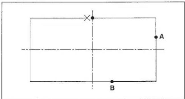
In case of changing a part of the sewing speed of the service pattern (No. 501)
Changing the sewing speed between A and B to 1,000 sti/min
1) Pressing the key, turn ON the power switch.
The feeding frame comes down and the origin retrieval is performed.
(Note) Keep the key held pressed until the display appears after the origin retrieval.
(2) Press the key.
3) Input 501 by the numeral key.
(This time, read out 100% without enlargement / reduction mode.)
4) Press the key.
5) Advance the feeding frame to A point by the 心 / 心 key.
6) Press the key.
7) Input ① ⑩ by the numeral key.
$$ \begin{array}{l} \begin{array}{l l} \text {O r i g i n} & - > > \ \mathrm {X} = + 0 0 0 0 0 \mathrm {A} \ \mathrm {Y} = + 0 0 0 0 0 \ \text {S e l e c t F u n c t i o n} \end{array} \ \begin{array}{l} \text {N o} = 1 2 3 \ \text {X} = 1 0 0 0 (0. 1 \%)\text {S} \ \text {Y} = 1 0 0 0 (0. 1 \%) \ \text {I n p u t R e a d} \end{array} \quad \text {N o} 0 8 0 \ \begin{array}{l} \text {N o} = 5 0 1 \ \text {X} = 1 0 0 0 (0. 1 \%)\text {S} \ \text {Y} = 1 0 0 0 (0. 1 \%) \ \text {I n p u t R e a d} \quad \text {N o} 0 8 0 \end{array} \ \begin{array}{l l} \text {O r i g i n} & - > > \ \text {X} = + 0 0 0 0 0 A & \ \text {Y} = + 0 0 0 0 0 & \ \text {S e l e c t F u n c t i o n} & \end{array} \ \begin{array}{l l} \text {L i n e a r} \ \mathrm {X = + 0 0 3 0 0 A} & \mathrm {P = 0 2 0} \ \mathrm {Y = + 0 0 0 1 0} & \mathrm {S = * *} \ \text {S e l e c t F u n c t i o n} \end{array} \ \begin{array}{l l} S = 2 5 (1 0 0 \mathrm {s p m}) \ \text {I n p u t S P} & \text {N o 0 6 1} \end{array} \ \begin{array}{l l} S = 1 0 (1 0 0 \text {s p m}) \ \text {I n p u t S P} & \text {N o 0 6 1} \end{array} \ \end{array} $$
8) Press the key.
9) Press the key, and move the feeding frame to the position B.
10) Press the key.
| Linear | |
| X = +00300A | P = 020 |
| Y = +00010 | S = * * |
| Chg Pt - Sp | N = 0001 |
| Linear | |
| X = + 00080A | P = 020 |
| Y = - 00150 | S = * * |
| Chg Pt - Sp | N = 0020 |
| Linear X = + 00080A P = 020 Y = -00150 S = 10 Select Function |
The s t t t t t t t t t t t t t t t t t t t t t t t t t t t t t t t t t t t t t t t t t t t t t t t t t t t t
When the feeding frame is moved by the / key, the indication of S = 10 is shown between A and B. It is, therefore, confirmed that the sewing speed has been changed.
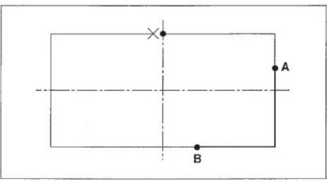
| Origin | ->> |
| X = +00000A | |
| Y = +00000 | |
| Select Function |
| No = 123 X = 1000 (0.1 %)S Y = 1000 (0.1 %) Input Read No 080 |
| No = 501 X = 1000 (0.1 %)S Y = 1000 (0.1 %) Input Read No 080 |
| Linear X = +00300A P = 020 Y = +00010 S = ** Chg Pt - Sp N = 0001 |
| Linear | |
| X = + 00080A | P = 020 |
| Y = - 00150 | S = * * |
| Chg Pt - Sp | N = 0020 |
| Linear X = +00080A P = 020 Y = -00150 S = 10 Select Function |
| Origin | ->> |
| X = + 00000A | |
| Y = + 00000 | |
| Select Function |
| No = 123 X = 1000 (0.1 %)S Y = 1000 (0.1 %) Input Read No 080 |
| No = 501 X = 1000 (0.1 %)S Y = 1000 (0.1 %) Input Read No 080 |
Origin ->>
X = +00000A
Y = +00000
Select Function
| Linear X = +00300A P = 020 Y = +00010 S = ** | |
| Select Function | |
| S = 25 (100 spm) | |
| Input SP | No 061 |
| S = 10 (100 spm) | |
| Input SP | No 061 |
| Linear | |
| X = +00300A | P = 020 |
| Y = +00010 | S = * * |
| Chg Pt - Sp | N = 0001 |
| Linear | |
| X = + 00080A | P = 020 |
| Y = - 00150 | S = * * |
| Chg Pt - Sp | N = 0020 |
| Linear X = +00080A P = 020 Y = -00150 S = 10 Select Function |
At first, input the arc ABC and the line CD. Then, input 3 stitches at the sewing start and 2 stitches at the sewing end.
1) Pressing key, turn ON the power switch.
The feeding frame comes down and the origin retrieval will be performed.
(Note) Keep the key held pressed until the display appears after the origin retrieval has been performed.
When the display appeared, insert a piece of paper or the like on which the shape of input is written under the feeding frame by raising / lowering the feeding frame by means of the feeding frame switch.
2) Press the key.
3) Move the feeding frame from 0 to A by the direction key.
4) Press the key.
5) Press the 2 key.
(The arc sewing is set in the F2 key at the time of delivery.)
6) Input in order by the numeral key, and press the key.
7) Move the feeding frame from A to B by the moving key, and indicate by the key.
Use the key for indicating the position when the circle or the arc is input.
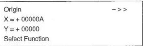
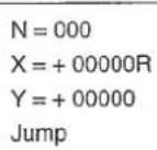
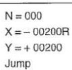
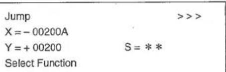
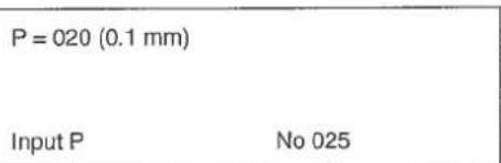
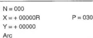
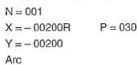
8) Move the feeding frame from B to C by the moving key, and indicate by the key.

N=002
X=+00000R P=030
Y=-00400
Arc
9) Press the key.
10) Press the key.
11) Press the key as the sewing pitch has not to be changed from 3mm .
12) Move the feeding frame from C to D by the moving key, and input by the key.
13) Press the key.
14) Press the key.
15) Press 0 6 4 in order by the numeral key, and press key. No = 064 of the back tuck is shown.
16) Press the key.
17) Press 3 by the numeral key, and press key. (Input 3 stitches, the number of back tuck stitches at the sewing start.)
18) Press 2 by the numeral key, and press key. (Input 2 stitches, the number of back tuck stitches at the sewing end.)
19) Indicate the type of back tuck. Take the V type for example, press 1, and press key.
1:Vtype
2:Ztype
Arc ->> X=-00200A P= Y=-00200 S= Select Function
P = 030 (0.1 mm)
Input P No 022
N=000
X = +00000R P=030
Y = +00000
Sewing
N = 001
X = +00500R P = 030
Y = +00000
Sewing
Linear >>>
X = +00300A P = 030
Y = -00200 S = *
Select Function
No = 000 Select Function
No = 64 Back-Tuck
= 0 EN = 0 T = 1(1:V,2:Z) Input~Num No 064
= 3 EN = 0 T = 1(1:V,2:Z) Input~Num No 064
SN = 3 EN = 2 T = 1 (1:V,2:Z)
Input Type No064
SN = 3 EN = 2 T = 1 (1:V,2:Z)
Input Num N
20) Press the key.
21) Advance to the final point by the key.
22) Press the key.
23) It is confirmed that the back tuck is made by means of the l or the l key.
The jump feed from 0 to A is automatically changed to 0 to A'.
| Linear | >>- |
| X = + 00300A | P = 030 |
| Y = - 00200 | S = * * |
| Select Function |
| Point | ->> |
| X = +00242A | |
| Y = -00200 | S = * * |
| Select Function |
| Thread Trimr | ->> |
| X = +00242A | |
| Y = -00200 | |
| Select Function |
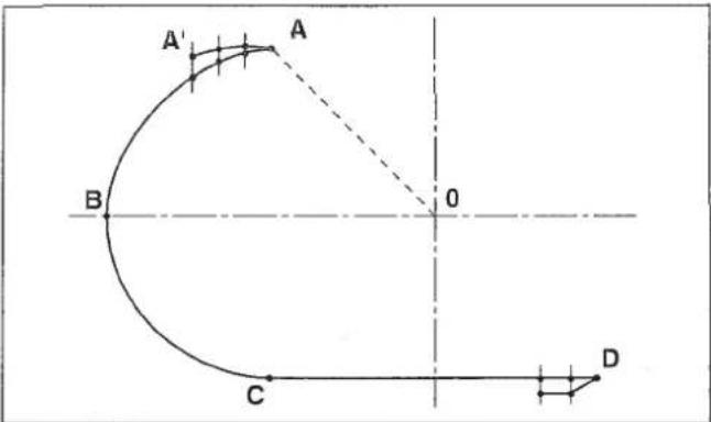
Linear >>> X = +00300A P = 030 Y = -00200 S = */ Select Function
No = 000 Select Function
No = 64 Back-Tuck
= 0 EN = 0 T = 1(1:V,2:Z) Input~Num
= 3 EN = 0 T = 1(1:V,2:Z) Input~Num No 064
= 3 EN = 2 T = 1(1:V,2:Z) Input~Type No064
= 3 EN = 2 T = 1(1:V,2:Z) Input~Num No064
Linear >>
X = +00300A P = 030
Y = -00200 S = **
Select Function
| Point | ->> |
| X = +00242A | |
| Y = -00200 | S = * * |
| Select Function |
| Thread Trimr | ->> |
| X = +00242A | |
| Y = -00200 | |
| Select Function |
| Origin | ->> |
| X = + 00000A | |
| Y = + 00000 | |
| Select Function |
| N = 000 |
| X = + 00000R |
| Y = + 00000 |
| Jump |
$$ \begin{array}{l} N = 0 0 0 \ X = - 0 0 2 0 0 R \ Y = + 0 0 2 0 0 \ J u m p \ \end{array} $$
Jump >>
X = -00200A
Y = +00200 S = * *
Select Function
$$ P = 0 2 0 (0. 1 \mathrm {m m}) $$
$$ \text {I n p u t} \mathrm {P} \quad \text {N o} 0 2 5 $$
$$ N = 0 0 0 $$
$$ X = + 0 0 0 0 0 R \quad P = 0 3 0 $$
$$ Y = + 0 0 0 0 0 $$
$$ \mathrm {A r c} $$
N=001
X=-00200R P=030
Y=-00200
Arc
N=002
X = +00000R P = 030
Y = -00400
Arc
Arc ->> X=-00200A P=030 Y=-00200 S = ** Select Function
P=030(0.1mm) Input P No 022
N=000
X = +00000R P=030
Y = +00000
Sewing
N=001
X = +00500R P = 030
Y = +00000
Sewing
Linear >>>
X = +00300A P = 030
Y = -00200 S = **Select Function
No = 000 Select Function
| Point | ->> |
| X = +00242A | |
| Y = -00200 | S = * * |
| Select Function |
| Thread Trim | ->> |
| X = +00242A | |
| Y = -00200 | |
| Select Function |
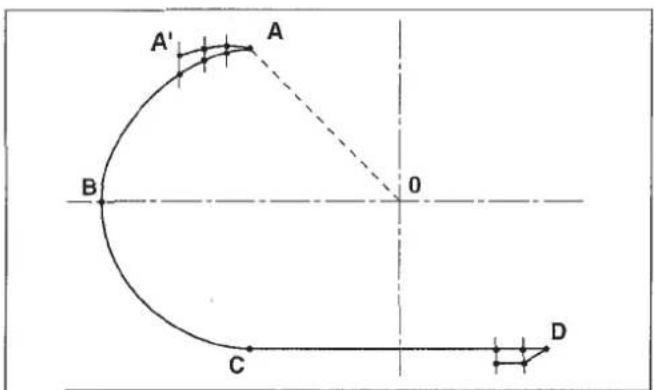
| Origin | ->> |
| X = +00000A | |
| Y = ÷ 00000 | |
| Select Function |
N = 000
X = +00000R
Y = +00000
Jump
N=000
X=-00200R
Y+=00200
Jump
Jump >>
X = -00200A
Y = +00200 S =
Select Function
P=020(0.1mm) Input P No 025
N=000
X = +00000R P=030
Y = +00000
Arc
N=001
X=-00200R P=030
Y=-00200
Arc
N=002
X = +00000R P = 030
Y = -00400
Arc
Arc - >>
X = -00200A P = 030
Y = -00200 S =
Select Function
P=030(0.1mm) Input P No 022
N=000
X=+00000R P=030
Y=+00000
Sewing
N=001
X = +00500R P = 030
Y = +00000
Sewing
Linear >>>
X = +00300A P = 030
Y = -00200 S = */
Select Function
At the start, make the linear sewing, A-B-C-D, and sewing pitch of 2.5 mm. And, the condensation stitching which makes the sewing pitch finer, is to be performed at the start and end of sewing.
Specify the numbers of the respective stitches at the start and end of sewing and the pitch of condensation stitching.
1) Pressing the key, turn ON the power switch.
(Note) Keep the key held pressed until the display appears after the origin retrieval has been performed.
When the display appeared, insert a piece of paper or the like on which the shape of input is written under the feeding frame by raising / lowering the feeding frame by means of the feeding frame switch.
2) Press the key.
3) Move the feeding frame from 0 to A by the direction key.
4) Press the key.
5) Press the key.
6) Press the numeral key in the order of 0 2 5, and press the key. (Stitch length 2.5mm )
7) Move the feeding frame from A to B by the moving key, and press the key.
8) Move the feeding frame from B to C by the moving key, and press the key.
$$ \begin{array}{l} \begin{array}{l l} \text {O r i g i n} & - > > \ \text {X} = + 0 0 0 0 0 A \ \text {Y} = + 0 0 0 0 0 \ \text {S e l e c t F u n c t i o n} \end{array} \ \begin{array}{l} N = 0 0 0 \ X = + 0 0 0 0 0 R \ Y = + 0 0 0 0 0 \ \text {J u m p} \end{array} \ \begin{array}{l} N = 0 0 0 \ X = - 0 0 2 5 0 R \ Y = + 0 0 1 5 0 \ \text {J u m p} \end{array} \ \end{array} $$
$$ \begin{array}{l} \begin{array}{l l} \hline \text {J u m p} & \gg > \ \text {X = + 0 0 2 5 0 A} \ \text {Y = + 0 0 1 5 0} & S = * * \ \text {S e l e c t F u n c t i o n} \end{array} \ \begin{array}{l} \mathrm {P = 0 2 0 (0 . 1 m m)} \ \text {I n p u t P} \quad \mathrm {N o 0 2 2} \end{array} \ \begin{array}{l} N = 0 0 0 \ X = + 0 0 0 0 0 R \quad P = 0 2 5 \ Y = + 0 0 0 0 0 \ \text {S e w i n g} \end{array} \ \begin{array}{l} \mathrm {N} = 0 0 1 \ \mathrm {X} = + 0 0 5 0 0 \mathrm {R} \ \mathrm {Y} = + 0 0 0 0 0 \ \text {S e w i n g} \end{array} \quad \mathrm {P} = 0 2 5 \ \begin{array}{l} N = 0 0 2 \ X = + 0 0 0 0 0 R \quad P = 0 2 5 \ Y = + 0 0 3 0 0 \ \text {S e w i n g} \end{array} \ \end{array} $$
9) Move the feeding frame from C to D by the moving key, and press the key.
10) Press the key.
11) Press the key.
12) Return to the sewing part by the key. Condensation stitching has to be specified over the sewing part.
13) Press the key.
14) Press the key to make the table shown.
15) Make the indication of the condensation stitching, No. 065, by operating the key.
16) Press the key.
17) Press 2 of the numeral key, and input it by the key. In this stage, the 2 stitches at the sewing start is changed to the condensation stitching.
18) Press 1 of the numeral key, and input it by the key. In this stage, the 1 stitch at the sewing end is changed to the condensation stitching.
19) Press 008 of the numeral key, and input by the key. The sewing pitch of the condensation stitching is set 0.8mm .
20) Press the key.
21) The confirmation of the shape can be made by the or key.
| N = 003 | |
| X = + 00500R | P = 025 |
| Y = - 00300 | |
| Sewing |
| Linear | >>> | |
| X = + 00250A | P = 025 | |
| Y = -00150 | S = * * | |
| Select Function |
| Thread Trim | ->> |
| X = + 00250A | |
| Y = - 00150 | |
| Select Function |
| Linear | ---> |
| X = + 00250A | |
| Y = - 00150 | S= * * |
| Select Function |
| No = 000 |
| Select Function |
| 001 = Thread Trimr |
| 002 = Sec - Origin |
| 003 = Temp Stop |
| 004 = Refer Point |
| 065 = Condensation | |
| 066 = Over Stitch | |
| 070 = Pt Del | R |
| 071 = Pt Move | R |
| SN = 0 | |
| EN = 0 | |
| P = 020 (0.1 mm) | |
| Input Num | No 065 |
| SN = 2 | |
| EN = 0 | |
| P = 020 (0.1 mm) | |
| Input Num | No 065 |
| SN = 2 |
| EN = 1 |
| P = 020 (0.1 mm) |
| Input P No 065 |
| SN = 2 | |
| EN = 1 | |
| P = 008 (0.1 mm) | |
| Input P | No 065 |
| Point | ->- |
| X = + 00250A | |
| Y = - 00150 | S = * * |
| Select Function |
Origin X = +00000A Y = +00000 Select Function
N=000
X+=00000R
Y+=00000
Jump
N=000
X=-00250R
Y+=00150
Jump
Jump >>
X = +00250A
Y = +00150 S = *
Select Function
P = 020 (0.1 mm)
Input P No 022
N=000
X = +00000R P=025
Y = +00000
Sewing
N=001
X = +00500R P = 025
Y = +00000
Sewing
N=002
X = +00000R P=025
Y = +00300
Sewing
N=003
X = + 00500R P = 025
Y = -00300
Sewing
| Linear | >> |
| X = +00250A | P = 025 |
| Y = -00150 | S = * * |
| Select Function |
| Thread Trimr | ->> |
| X = +00250A | |
| Y = -00150 | |
| Select Function |
| Linear | ->- |
| X = + 00250A | |
| Y = - 00150 | S= ** |
| Select Function |
| No = 000 |
| Select Function |
| 001 = Thread Trimr |
| 002 = Sec - Origin |
| 003 = Temp Stop |
| 004 = Refer Point |
| 065 = Condensation | |
| 066 = Over Stitch | |
| 070 = Pt Del | R |
| 071 = Pt Move | R |
| SN = 0 | |
| EN = 0 | |
| P = 020 (0.1 mm) | |
| Input Num | No 065 |
| SN = 2 | |
| EN = 0 | |
| P = 020 (0.1 mm) | |
| Input Num | No 065 |
| SN = 2 |
| EN = 1 |
| P = 020 (0.1 mm) |
| Input P No 065 |
| SN = 2 | |
| EN = 1 | |
| P = 008 (0.1 mm) | |
| Input P | No 065 |
| Point | ->- |
| X = + 00250A | |
| Y = -00150 | S = * * |
| Select Function |

$$ Y = + 0 0 0 0 0 $$
Select Function
$$ Y = + 0 0 0 0 0 $$
Jump
N=000
$$ X = - 0 0 2 5 0 R $$
$$ Y = + 0 0 1 5 0 $$
Jump
Jump
$$ X = + 0 0 2 5 0 A $$
$$ Y = + 0 0 1 5 0 \quad S = * * $$
Select Function
P=020(0.1mm)
Input P No 022
N=000
X = +00000R P = 025
$$ Y = + 0 0 0 0 0 $$
Sowing
N=001
X=+00500R P=025
Y=+00000
Sewing
N = 002
X = +00000R P = 025
Y = +00300
Sewing
N = 003
X = +00500R P = 025
Y = -00300
Sewing
N=003
X = +00500R P=025
Y=-00300
Sewing
| Linear | >> |
| X = + 00250A | P = 025 |
| Y = - 00150 | S = * * |
| Select Function |
| Thread Trim | ->> |
| X = + 00250A | |
| Y = - 00150 | |
| Select Function |
| Linear | ->- |
| X = + 00250A | |
| Y = - 00150 | S= ** |
| Select Function |
| No = 000 |
| Select Function |
| 001 = Thread Trim |
| 002 = Sec - Origin |
| 003 = Temp Stop |
| 004 = Refer Point |
| 065 = Condensation | |
| 066 = Over Stitch | |
| 070 = Pt Del | R |
| 071 = Pt Move | R |
| SN = 0 EN = 0 P = 020 (0.1 mm) Input Num | No 065 |
| SN = 2 | |
| EN = 0 | |
| P = 020 (0.1 mm) | |
| Input Num | No 065 |
| SN = 2 |
| EN = 1 |
| P = 020 (0.1 mm) |
| Input P No 065 |
| SN = 2 |
| EN = 1 |
| P = 008 (0.1 mm) |
| Input P No 065 |
| Point | ---> |
| X = + 00250A | |
| Y = -00150 | S = * * |
| Select Function |
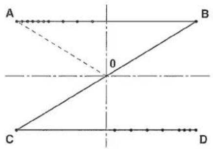
N=003
X = +00500R P=025
Y=-00300
Sewing
When inputting A-B-C-D-E-F using the function of the double-stitch sewing, double-stitch sewing of A-B-C-D-E-F-G-H can be made.
1) Pressing the key, turn ON the power switch.
(Note) Keep the key held pressed until the display appears after the origin retrieval has been performed.
When the display appeared, insert a piece of paper or the like on which the shape of input is written under the feeding frame by raising / lowering the feeding frame by means of the feeding frame switch.
2) Press the key.
3) Press the direction key, and move the feeding frame from 0 to A.
4) Press the key.
5) Press the key.
6) Press the key.
7) Press the 8 key, and select "Spline 2 Rvs".
8) Press the key.
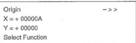
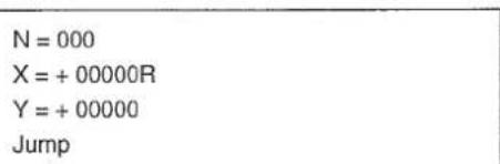
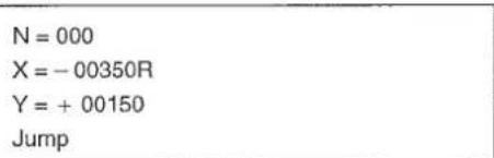

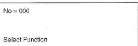
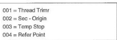
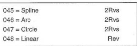
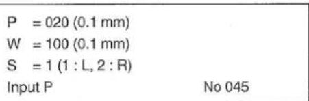
9) As the pitch is set 2 mm, press key.
10) As the width is set 4mm , indicate 040 by the numeral key, and press the key.
11) The sewing line is made on the right side of the advancing direction of the input line. So, indicate the right side. Press 2 of the numeral key, and press the key.
12) Press the key.
13) Move the feeding frame from A to B by the moving key, and press the key.
14) Move the feeding frame from B to C by the moving key, and press the key.
15) Move the feeding frame from C to D by the moving key, and press the key.
16) Move the feeding frame from D to E by the moving key, and press the key.
17) Move the feeding frame from E to F by the moving key, and press the ① key.
18) Press the key.
19) Press the key.
20) The procedures have been completed. Confirm the shape by operating the or key.
P = 020 (0.1 mm) W = 100 (0.1 mm) S = 1 (1:L,2:R) Input Wide No 045
P = 020 (0.1mm) W = 040 (0.1mm) S = 1 (1:L,2:R) Input Side No 045
P = 020 (0.1 mm) W = 040 (0.1 mm) S = 2 (1:L,2:R) Input P No 045
N=000
X = + 00000R P = 020
Y = + 00000 W = 040R
Spline 2Rvs
N=001
X = +00300R P = 020
Y = +00000 W = 040R
Spline 2Rvs
N=002
X = + 00400R P = 020
Y = -00050 W = 040R
Spline 2Rvs
N=003
X = + 00500R P = 020
Y = -00100 W = 040R
Spline 2Rvs
N=004
X = + 00600R P = 020
Y = -00200 W = 040R
Spline 2Rvs
N=005
X = +00650R P = 020
Y = -00300 W = 040R
Spline 2Rvs
Spline ->
X = -00350A P = 020
Y = +00110 S = ***
Select Function
Tread Trim > X = -00350A Y = +00110 Select Function
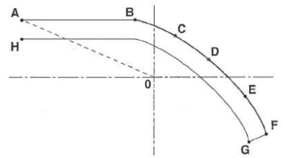
$$ Y = + 0 0 0 0 0 $$
Select Function
$$ N = 0 0 0 $$
$$ \mathrm {X} = + 0 0 0 0 0 \mathrm {R} $$
$$ Y = + 0 0 0 0 0 $$
Jump
$$ N = 0 0 0 $$
$$ X = - 0 0 3 5 0 R $$
$$ Y = + 0 0 1 5 0 $$
Jump
Jump
$$ X = - 0 0 3 5 0 A $$
$$ Y = + 0 0 1 5 0 \quad S = * * $$
Select Function
$$ \mathrm {N o} = 0 0 0 $$
Select Function
$$ 0 0 1 = \text {T h r e a d T r i m r} $$
$$ 0 0 2 = \text {S e c} - \text {O r i g i n} $$
$$ 0 0 3 = \text {T e m p S t o p} $$
004 = Refer Point
045 = Spline 2Rvs
046 = Arc 2Rvs
047 = Circle 2Rvs
048 = Linear Rev
P = 020 (0.1 mm)
W = 100 (0.1 mm)
S = 1(1:L,2:R)
Input P No 045
P = 020 (0.1 mm)
W = 100 (0.1 mm)
S = 1(1:L,2:R)
Input Wide No 045
Origin
X=+00000A
Y=+00000
Select Function
N=000
X=+00000R
Y=+00000
Jump
N=000
X=-00350R
Y=+00150
Jump
Jump
X=-00350A
Y=+00150 S=***
Select Function
No = 000
Select Function
001 = Thread Trim
002 = Sec - Origin
003 = Temp Stop
004 = Refer Point
045 = Spline 2Rvs
046 = Arc 2Rvs
047 = Circle 2Rvs
048 = Linear Rev
P = 020 (0.1 mm)
W = 100 (0.1 mm)
S = 1(1:L,2:R)
Input P No 045
P = 020 (0.1 mm)
W = 100 (0.1 mm)
S = 1 (1:L,2:R)
Input Wide No 045
P = 020 (0.1 mm)
W = 040 (0.1 mm)
S = 1 (1: L, 2: R)
Input Side No 045
P = 020 (0.1 mm)
W = 040 (0.1 mm)
S = 2 (1: L, 2: R)
Input P No 045
N = 000
X = +00000R P = 020
Y = +00000 W = 040P
Spline 2Rvs
N=001
X = +00300R P = 020
Y = +00000 W = 040P
Spline 2Rvs
N = 002
X = +00400R P = 020
Y = -00050 W = 040P
Spline 2Rvs
N = 003
X = +00500R P = 020
Y = -00100 W = 040R
Spline 2Rvs
N=004
X = +00600R P = 020
Y = -00200 W = 040R
Spline 2Rvs
N=005
X = +00650R P = 020
Y = -00300 W = 040R
Spline 2Rvs
Spline ->
X = -00350A P = 020
Y = +00110 S = *
Select Function
Tread Trimr ->
X = -00350A
Y = +00110
Select Function
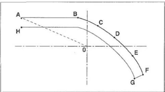
$$ Y = + 0 0 0 0 0 $$
Jump
N=000
$$ X = - 0 0 3 5 0 R $$
$$ Y = + 0 0 1 5 0 $$
Jump
Jump
$$ X = - 0 0 3 5 0 A $$
$$ Y = + 0 0 1 5 0 \quad S = * * $$
Select Function
No=000
Select Function
001 = Thread Trimr
002 = Sec - Origin
003 = Temp Stop
004 = Refer Point
045 = Spline 2Rvs
046=Arc 2Rvs
047 = Circle 2Rvs
048 = Linear Rev
P = 020 (0.1 mm)
W = 100 (0.1 mm)
S = 1(1:L,2:R)
Input P No 045
P = 020 (0.1 mm)
W = 100 (0.1 mm)
S = 1(1:L,2:R)
Input Wide No 045
After the circle, ABCE, is made, from the end point of the circle, E, the stitches are made so as to overlap N_1 , N_2 and N_3 .
1) Pressing the [ ] key, turn ON the power switch.
The feeding frame comes down, and the origin retrieval is performed.
(Note) Keep the key held pressed until the display is shown after the origin retrieval has been performed.
When the display appeared, insert a piece of paper or the like on which the shape of input is written under the feeding frame by raising / lowering the feeding frame by means of the feeding frame switch.
2) Press the key.
3) Move the feeding frame from 0 to A by the direction key.
4) Press the key.
5) Press the key.
6) Press the numeral key in the order of 0 2 6 The code of the circle sewing is 026.
7) Press the key. (You can omit this operation.)
$$ \begin{array}{l} \begin{array}{l} \text {O r i g i n} \ \text {X = + 0 0 0 0 0 A} \ \text {Y = + 0 0 0 0 0} \ \text {S e l e c t F u n c t i o n} \end{array} \ \begin{array}{l} N = 0 0 0 \ X = + 0 0 0 0 0 R \ Y = + 0 0 0 0 0 \ \text {J u m p} \end{array} \ \begin{array}{l} N = 0 0 0 \ X = + 0 0 0 0 0 R \ Y = + 0 0 2 5 0 \ \text {J u m p} \end{array} \ \begin{array}{l l} \text {J u m p} & > > > \ \text {X = + 0 0 0 0 0 A} \ \text {Y = + 0 0 2 5 0} & S = * * \ \text {S e l e c t F u n c t i o n} \end{array} \ \begin{array}{l} N = 0 0 0 \ \text {S e l e c t F u n c t i o n} \end{array} \ \begin{array}{l} N = 0 2 6 \ \text {S e l e c t F u n c t i o n} \end{array} \ \begin{array}{l} N = 0 2 6 \ \text {C i r c l e} \ \text {S e w i n g} \end{array} \ \end{array} $$
8) Press the key.
9) Input 3 mm (0 3 0) by the numeral key, and press the key.
10) Move the feeding frame from A to B by the moving key, and input by the key. (Use the key for inputting the circle and arc.)
11) Move the feeding frame from B to C by the moving key, and input by the key.
12) Press the key.
The feeding frame once returns in a straight line in the order of C B A and moves to the E point tracing the arc of A B C E .
13) Press the key.
14) Press the numeral key in the order of 0 6 8, and press the key.
15) Press the key.
16) Press the key.
17) Move the feeding frame to the position N_1 by the 或 key, and indicate by the 或 key.
Indication of the position for the overlapping stitching is performed by the 1 or key. The moving key is not effective.
18) Move the feeding frame to the position _2 by moving one stitch using the key, and indicate by the key.
| P=020(0.1mm) | |
| Input P | No 026 |
| N=000 | |
| X=+00000R | P=030 |
| Y=+00000 | |
| Circle | |
| N=001 | |
| X=+00250R | P=030 |
| Y=-00250 | |
| Circle | |
| N = 002 | |
| X = + 00000R | P = 030 |
| Y = - 00500 | |
| Circle |
| Circle | >> |
| X = +00000A | P = 030 |
| Y = +00250 | S = * * |
| Select Function |
| No = 000 |
| Select Function |
| No = 066 |
| Overlap Stitch |
| Sure (Y / C) |
| Over Stitch |
| Circle | >> |
| X = + 00000A | P = 030 |
| Y = + 00250 | S = ** |
| N = 000 |
| Circle | --- |
| X=+00030A | P=030 |
| Y=+00248 | S=* * |
| Over Stitch | N=0001 |
| Circle | --- |
| X=+00059A | P=030 |
| Y=+00243 | S=* * |
| Over Stitch | N=0002 |
19) Move the feeding frame to the position N_3 by moving one stitch using the key, and indicate by the key.
20) Press the key.
21) Press the key.
22) The procedures have been completed. Confirm the shape by the or 已 key.
| Circle | --- |
| X = + 00088A | P = 030 |
| Y = + 00234 | S = * * |
| Over Stitch | N = 0003 |
| Point | ->> |
| X = +00088A | |
| Y = +00234 | S = * * |
| Select Function | |
| Thread Trim | ->> |
| X = +00000A | |
| Y = +00234 | |
| Select Function |
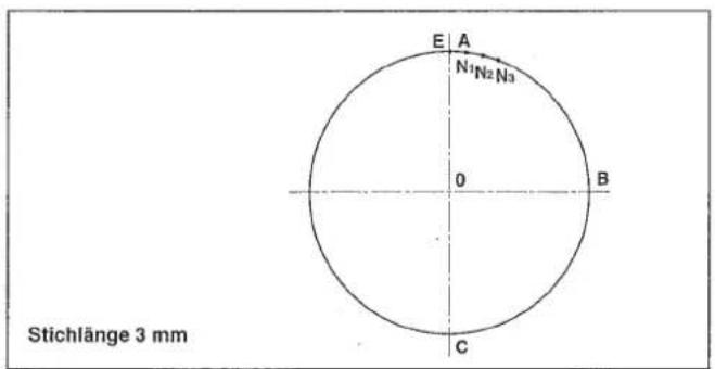
| Origin | ->> |
| X = + 00000A | |
| Y = + 00000 | |
| Select Function |
| N = 000 |
| X = + 00000R |
| Y = + 00000 |
| Jump |
| N = 000 |
| X = + 00000R |
| Y = + 00250 |
| Jump |
| Jump | >> |
| X = + 00000A | |
| Y = + 00250 | S = * * |
| Select Function |
N = 000
Select Function
N = 026
Select Function
N = 026
Circle
Sewing
P = 020 (0.1 mm)
Input P
N=000
X = +00000R P = 030
Y = +00000
Circle
N=001
X = +00250R P = 030
Y = -00250
Circle
N=002
X = +00000R P=030
Y = -00500
Circle
Circle >>> X = +00000A P = 030 Y = +00250 S = ** Select Function
No = 000 Select Function
No = 066 OverlapStitch
Sure (Y / C) Over Stitch
| Circle | >>> |
| X = + 00000A | P = 030 |
| Y = + 00250 | S = ** |
| N = 000 |
| Circle | --- |
| X = + 00030A | P = 030 |
| Y = + 00248 | S = * * |
| Over Stitch | N = 0001 |
| Circle | --- |
| X = + 00059A | P = 030 |
| Y = + 00243 | S = * * |
| Over Stitch | N = 0002 |
| Circle | --- |
| X = + 00088A | P = 030 |
| Y = + 00234 | S = * * |
| Over Stitch | N = 0003 |
| Point | ->> |
| X = +00088A | |
| Y = +00234 | S = * * |
| Select Function |
| Thread Trimr | ->> |
| X = + 00000A | |
| Y = + 00234 | |
| Select Function |
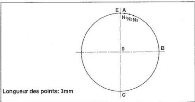
| N = 001 | |
| X = + 00250R | P = 030 |
| Y = - 00250 | |
| Circle |
| N = 002 | |
| X = + 00000R | P = 030 |
| Y = - 00500 | |
| Circle |
| Circle | >>> | |
| X = +00000A | P = 030 | |
| Y = +00250 | S = * * | |
| Select Function |
| No = 000 |
| Select Function |
| No = 066 |
| Overlap Stitch |
| Sure (Y / C) |
| Over Stitch |
| Circle | >>> | |
| X = + 00000A | P = 030 | |
| Y = + 00250 | S = ** | |
| N = 000 |
| Circle | |
| X = +00030A | P = 030 |
| Y = +00248 | S = * * |
| Over Stitch | N = 0001 |
| Circle | |
| X = + 00059A | P = 030 |
| Y = + 00243 | S = * * |
| Over Stitch | N = 0002 |
| Circle | |
| X = + 00088A | P = 030 |
| Y = + 00234 | S = * * |
| Over Stitch | N = 0003 |
| Point | ->> |
| X = +00088A | |
| Y = +00234 | S = * * |
| Select Function |
| Thread Trimr | ->> |
| X = + 00000A | |
| Y = + 00234 | |
| Select Function |
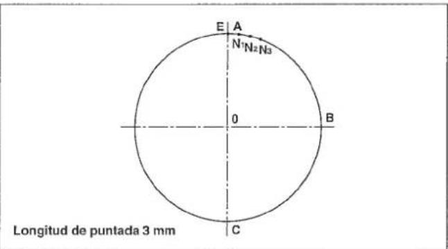
Després de着他 ABCE,de s else puto de extre mo del ciulo E,las puntadas se han de modo que se sobreponga N_1 N_2 y N_3
N=000
X = +00000R P=030
Y=+00000
Circle
N = 001
X = +00250R P = 030
Y = -00250
Circle
N = 002
X = +00000R P = 030
Y = -00500
Circle
Circle = +00000A Y = +00250 Select Function P=030 S = **
No = 000 Select Function
No = 066 OverlapStitch
Sure (Y / C) Over Stitch
Circle >>>
X = +00000A P = 030
Y = +00250 S =
N = 000
Circle
X = +00030A P = 030
Y = +00248 S = *
Over Stitch N = 0001
Circle
X = +00059A P = 030
Y = +00243 S = *
Over Stitch N = 0002
Circle
X = +00088A P = 030
Y = +00234 S = * *
Over Stitch N = 0003
Point ->> X = + 00088A Y = + 00234 S = * * Select Function
Thread Trim > X = +00000A Y = +00234 Select Function
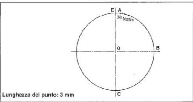
N=001
X=+00250R P=030
Y=-00250
Circle
N=002
X=+00000R P=030
Y=-00500
Circle
Circle >>>
X = +00000A P = 030
Y = +00250 S = ** Select Function
No = 000 Select Function
No = 066 OverlapStitch
Sure(Y/C) OverStitch
Circle >>>
X = +00000A P = 030
Y = +00250 S =
N = 000
Circle X=+00030A P=030 Y=+00248 S = ** OverStitch N=0001
Circle X = +00059A P=030 Y = +00243 S 水 OverStitch N=0002
Circle X=+00088A P=030 Y=+00234 S = ** OverStitch N=0003
Point - > X = + 00088A Y = + 00234 Select~Function S=*
Thread Trim > X = +00000A Y = +00234 Select Function
- Example 8 of pattern input (INVERSION PATTERN)
- BEISPIEL 8 DER MUSTEREINGABE (UMKEHRMUSTER)
- EXAMPLE 8 DE SAISIE D'UNE CONFIGURATION (CONFIGURATION A INVERSION)
- EJEMPLO 8 DE ENTRADA DE PATRON (PATRON DE INVERSION)
- ESEMPIO 8 DI IMMISSIONE DI MODELLO (MODELLO AD INVERSIONE)
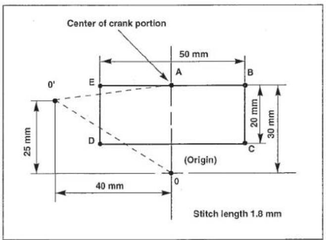
- Be sure to set the second origin and create a pattern since the inversion crank shaft may interfere with the needle. (Set the second origin to a place where leaves from the center of the inversion crank portion by 9 mm or more.)
- Set the reference point of enlargement/reduction at the sewing start point or in the center of the crank portion since the reference point of enlargement/reduction can be set optionally. (Initial setting is the mechanical origin.)
1) Pressing the key, turn ON the power switch.
The feeding frame comes down, and the origin retrieval is performed.
(Note) Keep the key held pressed until the display is shown after the origin retrieval has been performed. When the display appeared, insert a piece of paper or the like on which the shape of input is written under the feeding frame by raising / lowering the feeding frame by means of the feeding frame switch.
2) Press the key.
3) Input 0 and 1, and press the key.
:Without inversion function
2:Automatic inversion
3: Optional inversion
Press 2 or 3 key to specify the inversion function. After specifying the
function,press the key.
4) Press the key.
5) Move the presser to 0^ using the direction key.
6) Press the key.
Circle
$$ \begin{array}{l} \mathrm {X} = + 0 0 0 0 0 \mathrm {A} \ Y = + 0 0 0 0 0 \ \mathrm {C i r c l e} \ \end{array} $$
$$ N = 0 0 2 $$
Select Function
$$ M = 1 $$
$$ \begin{array}{l} N = 0 0 0 \ \mathrm {X} = + 0 0 0 0 0 \mathrm {R} \ Y = + 0 0 0 0 0 \ \mathrm {美 青 青 青 青} \ \end{array} $$
$$ \begin{array}{l} N = 0 0 0 \ \mathrm {X} = - 0 0 4 0 0 \mathrm {R} \ Y = + 0 0 2 5 0 \ \text {女 女 女 女} \ \end{array} $$
******* >>>>
$$ \begin{array}{l} X = - 0 0 4 0 0 A \ Y = + 0 0 2 5 0 \quad S = * * \ \text {★ ★ ★ ★ ★ ★} \ \end{array} $$
7) Press the Fj key.
(Caution) "Second origin" in the initial state is entered in the key. Set the second origin to a place where leaves from the center of the inversion crank portion by 9 mm or more.
8) Press the key.
9) Move the presser to A from 0^ using the direction key.
10) Press the key.
11) Press the key.
12) Input 0 and using the numeric key since the stitch length should be set to 1.8 mm, and press the key.
13) Move the presser to B from A using the direction key, and press the key.
14) Move the presser to C from B using the direction key, and press the key.
15) Move the presser to D from C using the direction key, and press the key.
16) Move the presser to E from D using the direction key, and press the key.
X=-000400A Y=+00250
N=000
X+=00000R
Y=-00000
N=000
X+=00400R
Y+=00050
\*\*\*\*\* X=+00000A Y=+00300 S=** Select Function
P = 020 (0.1 mm)
N=000
X = +00000R P = 018
Y = +00000
N=001
X = +00250R P = 018
Y = +00000
N=002
X = +00250R P = 018
Y = -00200
N=003
X=-00250R P=018
Y=-00200
N=004
X=-00250R P=018
Y+=00000
17) Move the presser to A from E using the direction key, and press the key.
N=005
$$ X = + 0 0 0 0 0 R \quad P = 0 1 8 $$
$$ Y = + 0 0 0 0 0 $$
$$ Y = + 0 0 3 0 0 $$
$$ S = * * $$
$$ \text {S e l e c t} $$
19) Press the >6 key.
★★★☆★★☆
一>>
The procedures have been completed. Confirm the shape by the or key.
$$ \mathrm {X} = + 0 0 0 0 0 \mathrm {A} $$
$$ Y = + 0 0 3 0 0 $$
$$ \text {S e l e c t} $$
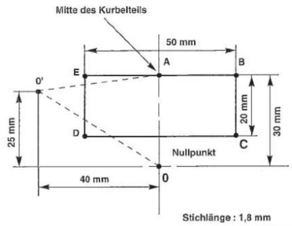
$$ Y = + 0 0 0 0 0 $$
Circle
$$ N = 0 0 2 $$
Select Function
$$ M = 1 $$
$$ N = 0 0 0 $$
$$ \mathrm {X} = + 0 0 0 0 0 \mathrm {R} $$
$$ Y = + 0 0 0 0 0 $$
$$ N = 0 0 0 $$
$$ X = - 0 0 4 0 0 R $$
$$ Y = + 0 0 2 5 0 $$
☆☆☆☆☆
$$ X = - 0 0 4 0 0 A $$
$$ Y = + 0 0 2 5 0 \quad S = * * $$
******
X=+00000A Y=+00300 S = ** Select Function
P=020(0.1mm)
N=000
X = +00000R P = 018
Y = +00000
**********
N=001
X = +00250R P = 018
Y = +00000
N=002
X = +00250R P = 018
Y = -00200
**********
N=003
X=-00250R P=018
Y=-00200
N=004
X=-00250R P=018
Y+=00000
$$ \begin{array}{l} X = + 0 0 0 0 0 A \quad P = 0 1 8 \ Y = + 0 0 3 0 0 \quad S = * * \ \text {S e l e c t} \ \end{array} $$
19) Taste drucken.
Circle ->>
X=+00000A
Y=+00000
Circle
N=002
Select Function
M=1
Circle
X=+00000A
Y=+00000
Circle
N=002
Select Function
M=1
N=000
X=+00000R
Y=+00000
青青青青青
N=000
X=-00400R
Y=+00250
南青南青
★★★★★
X=-00400A
S = * *
Y=+00250
X=·000400A
Y=+00250
★★★★★
\*\*\*\*
X = +00000A
Y = +00300 S = \*\*
Select Function
P = 020 (0.1 mm)
N=000
X = +00000R P = 018
Y = +00000
****
N=001
X = +00250R P = 018
Y = +00000
**********
N=002
X = +00250R P = 018
Y = -00200
N=003
X=-00250R P=018
Y=-00200
N=004
X=-00250R P=018
Y=+00000
*****
N=005
X = +00000R P = 018
Y = +00000
****
| ********** | >>>> |
| X = + 00000A | P = 018 |
| Y = + 00300 | S = * * |
| Select Function |
| ********** | ->> |
| X = + 00000A | |
| Y = + 00300 | |
| Select Function |
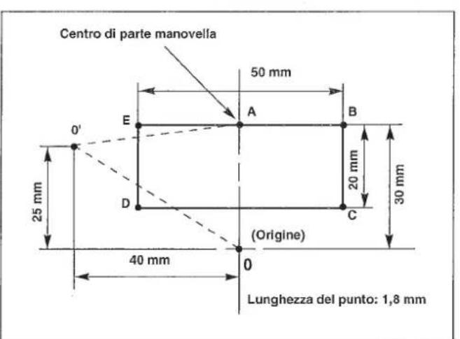
$$ Y = + 0 0 0 0 0 $$
Circle
$$ N = 0 0 2 $$
Select Function
$$ M = 1 $$
$$ N = 0 0 0 $$
$$ X = + 0 0 0 0 0 R $$
$$ Y = + 0 0 0 0 0 $$
女童女童女童
$$ N = 0 0 0 $$
$$ X = - 0 0 4 0 0 R $$
$$ Y = + 0 0 2 5 0 $$
★★★★
$$ \begin{array}{l} \text {区} \times \times \times \times \times \times \times \times \times \times \times \times \times \times \times \times \times \times \times \times \times \ X = - 0 0 4 0 0 A \ Y = + 0 0 2 5 0 \ \end{array} $$
-
EEP-ROM in addition to the floppy disk can be used.
1) Data ROM is mounted on U23 located on the MAIN circuit board. In addition, confirm that the switch is ON the switch on the [256] side. Part No. of ROM : HL011940000 (EEP-ROM, 58C256)
2) When the data ROM for the AMS-206 is used, change over the switch located on the circuit board to the [64] side. -
Neben Disketten kann auch das EEP-ROM verwendet werden.
1) Receding position of the presser (application of the 2nd origin)
Ther is a case where the preser is slanted and the material is hard to be set in accordance with the material. In this case, it is easier to set the material if the 2nd origin is set to near-by the center of the presser.
In case where the lift of the feeding frame is high, the feeding frame is likely to come in contact with the intermediate presser. In this case, it is recommended to set receding position of the presser (2nd origin) described in item 1) and to make a recess for the intermediate presser in the feeding frame blank.
Note) The input device is necessary when creating the sewing pattern.
By changing DIP SW1 1, DIP SW2 2, and SLIDE SW3 3 mounted on the control box, the setting can be changed as described in the following table. (Caution)
- Perform the change of the DIP SW and SLIDE SW after turning OFF the power switch.
- Do not turn ON the switch not used yet.
| Function | Change of needle bar stop height (It is possible to set ±7 stages by combination of the set value of DIP SW1-1 to -3 and the code setting of DIP SW2-1.) | ||||
| SW1-1 | SW1-2 | SW1-3 | SW1-4(unused) | Set value | Needle tip height at the time of UP stop |
| OFF | OFF | OFF | OFF | 0(State of delivery) | The height depends on the set value of DIP switch SW2-1 ②. |
| ON | OFF | OFF | OFF | 1 | |
| OFF | ON | OFF | OFF | 2 | DIP SW2-1 ON/Needle stop position - high OFF/Nneedle stop position - low |
| ON | ON | OFF | OFF | 3 | |
| OFF | OFF | ON | OFF | 4 | |
| ON | OFF | ON | OFF | 5 | |
| OFF | ON | ON | OFF | 6 | |
| ON | ON | ON | OFF | 7 | |
DIP SW2
| Function | ON | OFF | State of delivery | |
| SW2-1 | Selection of needle bar UP stop position code | High | Low | OFF |
| SW2-2 | Thread trimming speed setting | 250 sti/min | 400 sti/min | OFF |
| SW2-3 | Unused | - | - | OFF |
| SW2-4 | Unused | - | - | OFF |
| SW2-5 | Unused | - | - | OFF |
| SW2-6 | Unused | - | - | OFF |
| SW2-7 | Unused | - | - | OFF |
| SW2-8 | Unused | - | - | OFF |
SLIDE SW3
| Function | State of delivery |
| Unused | 3 side ON |
DIP SW1
When using the optional pedal, set the item of the memory switch as follows.
(Refer to "Setting the pedal specifications" described in the item of how to use the memory switch.)
| Memory switch setting | 1 pedal | 1 pedal (PK57) | 2-step pedal 2-step PK pedal 3-step pedal 3-step pedal (PK47) | |||
| No. | Function | Item | Set value | Set value | Set value | Contents |
| 032 | Pedal 1 | Pedal 1 | Non-latch | Non-latch | Latch | Operation of feeding frame 1 |
| Pedal 2 | Latch | Latch | Latch | Operation of feeding frame 2 | ||
| Pedal 3 | Latch | Latch | Latch | Operation of feeding frame 3 | ||
| 033 | Pedal 2 | Pedal 4 | Latch | Latch | Latch | Operation of feeding frame 4 |
| 098 | Pedal 3 | Pedal 1 active | HIGH | LOW | LOW | Logic of switch 1 |
| Pedal 2 active | LOW | LOW | LOW | Logic of switch 2 | ||
| Pedal 3 active | LOW | LOW | LOW | Logic of switch 3 | ||
| 099 | Pedal 4 | Pedal 4 active | LOW | LOW | LOW | Logic of switch 4 |
| Start pedal active | LOW | LOW | LOW | Logic of start switch | ||
1) Remove the standard pedal cords from J18 and J26 connectors on the MAIN circuit board.
2) Enter the 2-step pedal cord into the control box and connect it with J26 connector on the MAIN circuit board.
2-step pedal : Part No. M85205800A0
1) Remove the standard pedal cord from J19 and J20 connector on the MAIN circuit board, and connect PK-57 change cable 1 to J20 connector.
2) Connect the cord of PK-57 with J71 of PK-57 change cable at the rear face of the control box. Then, clamp two places with adhesive clamp ±b2
Also, tighten with a screw the PK-57 ground cable as illustrated in the figure.
PK-57 :Part No.GPK570010B0
PK-57 change cable : Part No. M90135900A0
Adhesive clamp : Part No. E9607603000 (2 pcs.)
1) Remove the pedal cords from J18 and J26 connectors on the MAIN circuit board.
2) Enter the 2-step PK pedal cord into the control box, connect it with the 2-step pedal connecting cord asm. 1, and connect it with J26 connector on the MAIN circuit board.
2-step PK pedal : Part No. M85905130AA
2-step pedal connecting cord asm. : Part No. M90315800A0
| Error No. | Indicator lamp | Error description | How to reset |
| E3 | ServoMotor Alert | Main shaft motor failure | After turning OFF the switch, remove the trouble. |
| E4 | ServoMotorFeeder Sync error | Timing of main shaft and feed is not correct. | After turning OFF the switch, remove the trouble. |
| E10 | No Pattern Found | The pattern is not found in the floppy disk. | Set again the correct pattern No. |
| E11 | No Disk In Drive | The floppy disk has not been loaded. | Set the floppy disk. |
| E12 | Err Has Occurred When Reading | Error has occurred due to some reasons when reading from the floppy disk. | Read again with the ready switch. |
| E13 | Err Has Occurred When Writing | Error has occurred due to some reasons when writing in the floppy disk. | Write again with the ready switch. |
| E14 | The Write-ptct Tab Is Locked | The write-protect tab of the floppy disk is locked. | Release the write-protect tab of the floppy disk, and write again. |
| E15 | Formatting Error | Initializing of the floppy disk cannot be made. | Initialize the floppy disk again, or the floppy disk is broken. |
| E16 | The FD Is Full | The floppy disk is full. | Replace with a new initialized floppy disk, write again. |
| E17 | The ROM Is Full | Data ROM is one piece. | Replace the EEP-ROM with a new one. |
| E18 | Illegal media Type | Data ROM is a different type. | Use a correct ROM. |
| E19 | File Size Is Over | Processing is impossible since the pattern data size is too large. | The pattern cannot be used since it exceeds the specified limit. |
| E20 | Scaling Range 10 Through 4000 | Scaling range of X, Y is beyond the setting range. | Change to the correct set value, and read again with the ready switch. |
| E21 | Processing Aborted | During data computation temporary stop key is pressed or computation failure has occurred. | Read again with the ready switch. |
| E22 | Maximum No of Stitch Excd | Due to too many data, computation is impossible. | The pattern is too large, and cannot be used. |
| E25 | Reset Counter | Bobbin thread counter has reached to the set value. | Reset the bobbin thread counter with the bobbin thread replacement key. |
| E27 | Combination No Data Stored | Under combination mode, no data is read in. | After specifying pattern No., read the pattern data. |
| E30 | Needle Pos Err | Main shaft is not at the upper dead point or upper position. | Return to the upper position by ON/OFF of the threading key. |
| E31 | AirPressure Drop | Air pressure dropped. Air is not supplied. Air relay cable is removed. | After turning OFF of the power, set the air pressure to 0.5 to 0.55 MPa (5 to 5.5kgf/cm²), or insert the connector. |
| E32 | Air Pressure, OK | Air pressure is OK. | Automatically indicated when the air is returned. |
| E33 | Travel OverLimit | Feeding frame is beyond the sewing range. | During sewing: Release with the return-to-origin switch. |
| E34 | Travel Limit Correct Pattern | After computation in case of offset, 2-line sewing, etc., this occurs when the travel limit is over. | Correct the pattern while it is input. |
| E35 | Wait For Input Timeout | External input signal is not input within the set time. | Make sure the external input signal. Return to the sewing start point with the return-to-origin switch. |
| E36 | Fan Alarm | The temperature inside the electrical box has risen. | Turn OFF the power switch. Then, clean up the fan of the electrical box. |
| E37 | Fan Alarm Cancel | The temperature rise error has been reset. | This message will automatically appear on the display when the temperature rise error is reset. |
| E40 | Feeding Frame Lifted Due To A | When a pattern is input, feed forward/backward key is operated while the feeding frame is lifted. | After the feeding frame has come down, operate the forward/backward key. |
| E41 | Misoperation Calculation Error | Indicated when operation on the program is not operative. | Usually, this error does not occur. |
| E42 | The Data Contain The Max Stch Lg | In case of circle sewing, arc sewing, etc., input of turning point is input to the linear or the like. | Input again. |
| E43 | Stch No. Limit Process Intrpt | Read-in data contain data beyond the max. stitch length. | Read again the correct data. |
| E44 | The Data Read Contain An Error | Due to too many input data, memory range is over. | The input pattern should be input by separating in small division. Or, if the input pattern is too big, separate the number of stitches into the limit of stitches. |
| E45 | A Hardware Err Has Occurred | Pattern data read is broken. | Floppy disk is broken or error at the time of read is considered. Read again. |
| E46 | Stopkey Accepted | Error occurred when the sewing machine is operated at the time that feed forward/backward key does not operate properly. | Failure of the electrical components. Turn OFF the power, and contact our business office or dealers. |
| E50 | Stopkey Accepted | Temporary stop key is pressed, and the machine is in a state of stopping. | Re-start with start switch, or move to the sewing start point using return-to-origin key, and start again the sewing. |
| E51 | Not Trimmed Yet | Temporary stop key is pressed, and the machine is in a state of stopping without thread trimming. | Make thread trimming using threading or temporary stop switch. Then, the machine is in a state of temporary stop. |
| E52 | Thread Broken | Needle thread breakage is detected, and the machine stopped. | Thread the needle thread, and start again. |
| E90 | No MSW Data Found | No data on the memory switch is stored on a floppy disk. | Load another floppy disk on which memory switch data are written. |
| E91 | The MSW Data Contain An Error | The memory switch data is for another model of machine or of a predecessor version. | Load another floppy disk on which data are written using your machine. |
| E100 to E107 | AMS-Panel Connection Error | Connection error of operation panel and MAIN circuit board | There are troubles in operation panel or MAIN circuit board. |
5. Troubles and corrective measures (Sewing conditions)
| Trouble | Cause | Corrective measures | Page |
| 1. The needle thread slips off at the start of bar-tacking. | ① Stitches are slipped at the start.2 The needle thread remaining on the needle after thread trimming is too short.3 The bobbin thread is too short. | ○ Adjust the clearance between the needle and the shuttle to 0.05 to 0.1 mm.○ Set soft-start sewing at the start of bartacking.○ Correct the thread tension release timing of the thread tension controller No. 2.○ Increase the tension of the thread take-up spring, or decrease the tension of the thread tension controller No. 1.○ Decrease the tension of the bobbin thread.○ Increase the clearance between the needle hole guide and the counter knife. | 595931-323163 |
| 2. Thread often breaks or synthetic fiber thread splits finely. | ① The shuttle or the driver has scratches.② The needle hole guide has scratches.③ Fibrous dust is in the groove of the shuttle race.④ The needle thread tension is too high.⑤ The tension of the thread take-up spring is too high.⑥ The synthetic fiber thread melts due to heat generated on the needle. | ○ Take it out and remove the scratches using a fine whetstone or buff.○ Buff or replace it.○ Take out the shuttle and remove the fibrous dust from the shuttle race.○ Reduce the needle thread tension.○ Reduce the tension.○ Use silicone oil. | 3132224 |
| 3. The needle often breaks. | ① The needle is bent.② The needle is too thin for the material.③ The driver excessively bends the needle.④ Feed trimming is excessively slow. | ○ Replace the bent needle.○ Replace it with a thicker needle according to the material.○ Correctly position the needle and the shuttle.○ Make the feeding timing fast. | 2760 |
| 4. Treads are not trimmed. | ① The counter knife is dull.② The difference in level between the needle hole guide and the counter knife is not enough.③ The moving knife has been improperly positioned.④ The last stitch is skipped. | ○ Replace the counter knife.○ Increase the bend of the counter knife.○ Correct the position of the moving knife.○ Correct the timing between the needle and the shuttle. | 6359 |
| 5. Stitch skipping often occurs. | ① The motions of the needle and shuttle are not properly synchronized.② The clearance between the needle and shuttle is too large.③ The needle is bent.④ The driver excessively bends the needle. | ○ Correct the positions of the needle and shuttle.○ Correct the positions of the needle and shuttle.○ Replace the bent needle.○ Correctly position the driver. | 5959589 |
| 6. The needle thread comes out on the wrong side of the material. | ① The needle thread tension is not high enough.② The needle thread after thread trimming is too long. | ○ Increase the needle thread tension.○ Make the feed timing slow.○ Increase the tension of the thread tension controller No. 1. | 316131 |
| 7. Threads break at time of thread trimming. | ① The moving knife has been improperly position. | ○ Correct the position of the moving knife. | 63 |
| 8. When synthetic fiber thread is used, at the start or end of sewing, needle thread rises or remaining of needle thread is excessive. | ① In case of synthetic fiber thread, the thread is harder than other threads and penetration resistance to material is small. | ○ When making a pattern, set the sewing pitch at the start and end of sewing to 1 mm or less. |
Turn OFF the power before starting the work so as to prevent accidents caused by abrupt start of the sewing machine.
WARNING :
When synthetic fiber thread is used, fix silicon tank 1 (B92118500A0) with setscrew 2.
PHONE:(81)42-357-2371
FAX:(81)42-357-2380
http://www.juki.com
Copyright © 2010-2013 JUKI CORPORATION
- All rights reserved throughout the world.
Alle Rechte weltweit vorbehalten.
Tous droits réserves partout dans le monde. - Reservados todosarethos en el mundo entero.
- Tutti i diritti sono riservati in tutto il mondo.
Please do not hesitate to contact our distributors or agents in your area for further information when necessary.