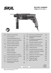
1763 AK - Hammer SKIL - Free user manual and instructions
Find the device manual for free 1763 AK SKIL in PDF.



| Product type | Rotary hammer |
| Brand | Skil |
| Model | 1763 AK |
| Chuck system | SDS+ |
| Operating modes | Normal drilling, hammer drilling, rotary chiseling, fixed chiseling |
| Variable speed | Yes, stepless adjustment via wheel |
| Safety clutch | Yes, in case of accessory jamming |
| Auxiliary handle | Yes, adjustable |
| Depth gauge | Yes |
| 13 mm chuck adapter | Included |
| Supply voltage | 230 V AC |
| Double insulation | Yes (class II) |
| Sound pressure level | 91 dB(A) |
| Sound power level | 102 dB(A) |
| Vibration (hammering) | 12.3 m/s² |
| Vibration (chiseling) | 10.9 m/s² |
| Weight | Approximately 4.5 kg |
| Maintenance and cleaning | Clean ventilation slots; disconnect before cleaning |
| Safety | Double insulation, emergency stop, switch lock for continuous operation |
| Spare parts and repairability | Repair by SKIL authorized service center; use original accessories |
Frequently Asked Questions - 1763 AK SKIL
User questions about 1763 AK SKIL
0 question about this device. Answer the ones you know or ask your own.
Ask a new question about this device
Download the instructions for your Hammer in PDF format for free! Find your manual 1763 AK - SKIL and take your electronic device back in hand. On this page are published all the documents necessary for the use of your device. 1763 AK by SKIL.
USER MANUAL 1763 AK SKIL
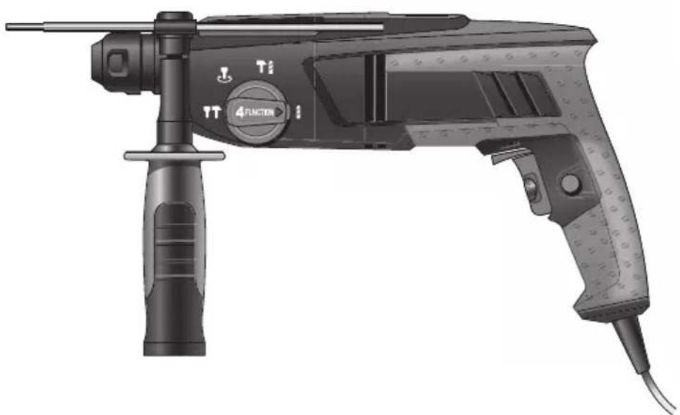
natural_image
Illustration of a multi-functional mechanical tool with no visible text or symbols
GB ORIGINAL INSTRUCTIONS 11
F NOTICE ORIGINALE 14
D ORIGINALBETRIEBSANLEITUNG 18
NL ORIGINELE GEBRUIKSAANWIJZING 21
S BRUKSANVISNING I ORIGINAL 25
DK ORIGINAL BRUGSANVISNING 28
N ORIGINAL BRUKSANVISNING 32
FIN ALKUPERÄISET OHJEET 35
E MANUAL ORIGINAL 38
P MANUAL ORIGINAL 42
I ISTRUZIONI ORIGINALI 45
H EREDETI HASZNÁLATI UTASÍTÁS 49
CZ PÚVODNÍM NÁVODEM K POUŽÍVÁNÍ 53
TR ORİJINAL İŞLETME TALİMATI 56
PL INSTRUKCJA ORYGINALNA 59
UA ОРИГІНАЛЬНА ІНСТРУКЦІЯ
З ЕКСПЛУАТАЦІЇ 63
GR ΠΡΩΤΟΥΠΟ ΟΔΗΓΙΩΝ ΧΡΗΣΗΣ 67
RO INSTRUCTIUNI DE FOLOSIRE
ORIGINALE 71
BG ОРИГИНАЛНО РЪКОВОДСТВО
ЗА ЕКСПЛОАТАЦИЯ 75
SK PÔVODNÝ NÁVOD NA POUŽITIE 79
HR ORIGINALNE UPUTE ZA RAD 82
SRB ORIGINALNO UPUTSTVO ZA RAD 86
SLO IZVIRNA NAVODILA 89
EST ALGUPÄRANE KASUTUSJUHEND 92
LV ORIGINĀLĀ LIETOŠANAS PAMĀCĪBA 95
LT ORIGINALI INSTRUKCIJA 99
МК ИЗВОРНО УПАТСТВО ЗА РАБОТА 103
AL UDHËZIMET ORIGJINALE 107
AR دليل الاستعمال 116
④ RAHENMAI AUSLI 114
www.skil.com

CE
1763
| GB | EU Declaration of conformityRotary hammer Article number | We declare under our sole responsibility that the stated products comply with all applicable provisions of the directives and regulations listed below and are in conformity with the following standards.Technical file at:* |
| F | Déclaration de conformité UEMarteau perforateur Numéro d'article | Nous déclarons sous notre propre responsabilité que les produits décrits sont en conformité avec les directives, règlements normatifs et normes énumérés ci-dessous.Dossier technique auprès de:* |
| D | EU-KonformitätserklärungBohrhammer Sachnummer | Wir erklären in alleiniger Verantwortung, dass die genannten Produkte allen einschlägigen Bestimmungen der nachfolgend aufgeführten Richtlinien und Verordnungen entsprechen und mit folgenden Normen übereinstimmen.Technische Unterlagen bei* |
| NL | EU-conformiteitsverklaringBoorhamer Productnummer | Wij verklaren op eigen verantwoordelijkheid dat de genoemde producten voldoen aan alle desbetreffende bepalingen van de hierna genoemde richtlijnen en verordningen en overeenstemmen met de volgende normen.Technisch dossier bij* |
| S | EU-konformitetsförklaringBorrhammare Produktnummer | Vi förklarar under eget ansvar att de nämnda produkterna uppfyller kraven i alla gällande bestämmelser i de nedan angivna direktiven och förordningarnas och att de stämmer överens med följande normer.Teknisk dokumentation* |
| DK | EU-overensstemmelseserklæringBorehammer Typenummer | Vi erklærer som eneansvarlige, at det beskrevne produkt er i overensstemmelse med alle gældende bestemmelser i følgende direktiver og forordninger og opfylder følgende standarder.Tekniske bilag ved* |
| N | EU-samsvarserklæringBorhammer Produktnummer | Vi erklærer under eneansvar at de nevnte produktene er i overensstemmelse med alle relevante bestemmelser i direktivene og forordningene nedenfor og med følgende standarder.Teknisk dokumentasjon hos* |
| FIN | EU-vaatimustenmukaisuusvakuutusPoravasara Tuotenumero | Vakuutamme täten, että mainitut tuotteet vastaavat kaikkia seuraavien direktiivien ja asetusten asiaankuuluvia vaatimuksia ja ovat seuraavien standardien vaatimusten mukaisia.Tekniset asiakirjat saatavana* |
| E | Declaración de conformidad UEMartillo perforador Número de artículo | Declaramos bajo nuestra exclusiva responsabilidad, que los productos nombrados cumplen con todas las disposiciones correspondientes de las directivas y los reglamentos mencionados a continuación y están en conformidad con las siguientes normas.Documentos técnicos de:* |
| P | Declaração de conformidade CEMartelo perfurador Número do produto | Declaramos sob nossa exclusiva responsabilidade que os produtos mencionados cumprem todas as disposições e os regulamentos indicados e estão em conformidade com as seguintes normas.Documentação técnica pertencente à:* |
| I | Dichiarazione di conformità UEMartello perforatore Codice prodotto | Dichiariamo sotto la nostra piena responsabilità che i prodotti indicati sono conformi a tutte le disposizioni pertinenti delle direttive e dei regolamenti elencati di seguito, nonché alle seguenti normative.Documentazione tecnica presso:* |
| H | EU konformitási nyilatkozatFúrókalapács Cikkszám | Egyedüli felelöséggel kijelentjük, hogy a megnevezett termékek megfelelnek az alábbiakban felsorolásra kerülő irányelvek és rendeletek valamennyi idevágó előírásainak és megfelelnek a következő szabványoknak.Műszaki dokumentumok megőrzési pontja:* |
| CZ | EU prohlášení o shoděVrtací kladivo Objednací číslo | Prohlašujeme na výhradní zodpovědnost, že uvedený výrobek splňuje všechna příslušná ustanovení niže uvedených směrnic a nařizení a je v souladu s následujícími normami.Technické podklady u:* |
| TR | AB Uygunluk beyaníKırıcı-delici Ürün kodu | Tek sorumlu olarak, tanımlanan ürünün aşağıdaki yönetmelik ve direktiflerin geçerli bütün hükümlerine ve ašağıdaki standartlara uygun olduğunu beyan ederiz.Teknik belgelerin bulunduğu yer:* |
| PL | Deklaracja zgodności UEMłot udarowo-obrotowy Numer katalogowy | Oświadczamy z pełną odpowiedzialnością, że niniejsze produkty odpowiadają wszystkim wymaganiom poniżej wyszczególnionych dyrektyw i rozporządzeń, oraz ze są zgodne z następującymi normami.Dokumentacja techniczna:* |
| RU | Заявление о соответствии ЕСПерфоратор Товарный номер | Мы заявляем под нашу единоличную ответственность, что названные продукты соответствуют всем действующим предписаниям нижеуказанных директив и распоряжений, а также нижеуказанных норм.Техническая документация хранится у:* |
| UA | Заява про відповідність ЄССперфоратор Товарний номер | Мизаявляемо під нашу одноособову відповідальність, що названі вироби відповідають усім чинним положенням нищеозначених директив і розпоряджень, а також нижчеозначеним нормам.Технична документация зберігається у:* |
CE
1763
| GR | Δήλωση πιστότητας EE | Δηλώνουμε με αποκλειστική μας ευθύνη, ότι τα αναφερόμενα προϊόντα αντιστοιχούν σε όλες τις σχετικές διατάξεις των πιο κάτω αναφερόμενων οδηγιών και κανονισμών και ταυτίζονται με τα ακόλουθα πρότυπα. | |
| Περιστροφικό πιστολέτο | Αριθμός ευρετηρίου | Τεχνικά έγγραφα στη:* | |
| RO | Declaratie de conformitate UE | Declarăm pe proprie răspundere că produsele menționate corespund tuturor dispozițiilor relevante ale directivelor și reglementărilor enumerate în cele ce urmează și sunt în conformitate cu următoarele standarde.Documentație tehnică la:* | |
| Ciocan rotopercutor | Număr de identificare | ||
| BG | EC декларация за съответствие | С пълна отговорност ние декларираме, че посочените продукти отговарят на всички валидни изисквания на директивите и разпоредбите по-долу и съответства на следните стандарти. | |
| Перфоратор | Каталожен номер | Техническа документация при:* | |
| SK | EU vyhlásenie o zhode | Vyhlasujeme na výhradnú zodpovednosť, že uvedený výrobok splína všetky príslušné ustanovenia nižšie uvedených smerníc a nariadení a je v súlade s nasledujúcimi normami.Technické podklady má spoločnosť:* | |
| Výtací kladivo Vecné číslo | |||
| HR | EU izjava o sukladnosti | Pod punom odgovornošću izjavljujemo da navedeni proizvodi odgovaraju svim relevantnim odredbama direktiva i propisima navedenima u nastavku i da su sukladni sa sljedećim normama.Tehnička dokumentacija se može dobiti kod:* | |
| Bušaći čekić Kataloški broj | |||
| SRB | EU-izjava o usaglašenosti | Na sopstvenu odgovornost izjavljujemo, da navedeni proizvodi odgovaraju svim dotičnim odredbama naknadno navedenih smernica u uredaba i da su u skladu sa sledećim standardima.Tehnička dokumentacija kod:* | |
| Bušilica čekić Broj predmeta | |||
| SLO | Izjava o skladnosti ES | Izjavljamo pod izključno odgovornostjo, da je omenjen izdelek v skladu z vsemi relevantnimi določili direktiv in uredb ter ustreza naslednjim standardom.Tehnična dokumentacija pri:* | |
| Vrtalno kladivo Številka artikla | |||
| EST | EL-vastavusdeklaratsioon | Kinnitame ainuvastutajatena, et nimetatud tooted vastavad järgnevalt loetletud direktiivide ja määruste köikidele asjaomastele nõuetele ja on kooskõlas järgmiste normidega.Tehnilised dokumentid saadaval:* | |
| Puurvasar Tootenumber | |||
| LV | Deklaracija par atbilstību EK standartiem | Mês ar pilnu atbildību pazinojam, ka šeit aplūkotie izstrādājumi atbilst visiem tālāk minētajās direktīvās un rīkojumos ietvertajām saistošajām nostādnēm, kā arī sekojošiem standartiem.Tehniskā dokumentacija no:* | |
| Perforators | Izstrādājuma numurs | ||
| LT | ES atitikties deklaracija | Atsakingai pareiškiame, kad išvardyti gaminiai atitinka visus privalomus žemiau nurodyty direktyvų ir reglamentų reikalavimus ir šiuos standartus.Techninė dokumentacija saugoma:* | |
| Perforatorius Gaminio numeris | |||
| MK | EU-Изjava za сообразност | Со целосна одговорност изјавуваме, дека опишаните производи се во согласност со сите релевантни одредби на следните регулативи и прописи и се во согласност со следните норми.Техничка документација кaj:* | |
| Ударна дупчалка Број на артикл | |||
| AL | EU Deklarata e konformitetit | Ne deklarojmė me përgjegjësinė tonė tė vetme se produktet e paraqitura janė nė përputhje me tė gjitha dispozitat e zbatueshme tė direktivave dhe rregulloreve tė listuara mė poshtė dne janė nė përputhje me standardet si mė poshtė.Dosja teknike nė:* | |
| Trapan çekić Numri i nenit | |||
| 1763 F0151763.. | 2006/42/EC EN 60745-1:2009 + A11:20102014/30/EU EN 60745-2-6:20102011/65/EU EN 55014-1:2006 + A1:2009 + A2:2011EN 55014-2:2015EN 61000-3-2:2014EN 61000-3-3:2013EN 50581: 2012 | ||
| SKIL* Skil BVKonijnenberg 624825 BD BredaThe Netherlands | |||
Olaf DijkgraafApproval Manager Skil BV, Konijnenberg 62, 4825 BD Breda, NL17.12.2018 Skil BV, Konijnenberg 62, 4825 BD Breda, NL17.12.2018 |


flowchart
graph TD
    A["STOP"] --> B["Arrow to Arrow"]
    B --> C["Arrow to Arrow"]
    C --> D["STOP"]

flowchart
graph LR
    A["11: Surface with 3 particles"] --> B["2: Molded composite material"]
    B --> C["1: Plastic structure with PLASTICS"]
    C --> D["4: Final product with E and F labels"]
    D --> E["4: Final product with T and T arrows indicating process flow"]
    style A fill:#f9f,stroke:#333
    style B fill:#ccf,stroke:#333
    style C fill:#cfc,stroke:#333
    style D fill:#fcc,stroke:#333
    style E fill:#ffc,stroke:#333

GB
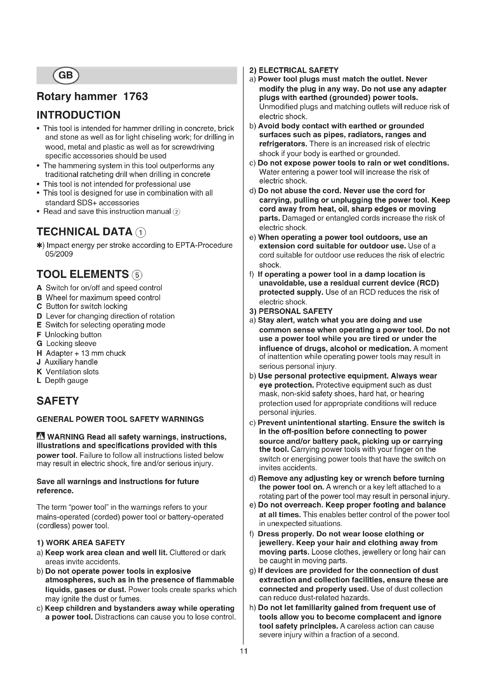
Rotary hammer 1763
INTRODUCTION
- This tool is intended for hammer drilling in concrete, brick and stone as well as for light chiseling work; for drilling in wood, metal and plastic as well as for screwdriving specific accessories should be used
- The hammering system in this tool outperforms any traditional ratcheting drill when drilling in concrete
• This tool is not intended for professional use - This tool is designed for use in combination with all standard SDS+ accessories
- Read and save this instruction manual ②
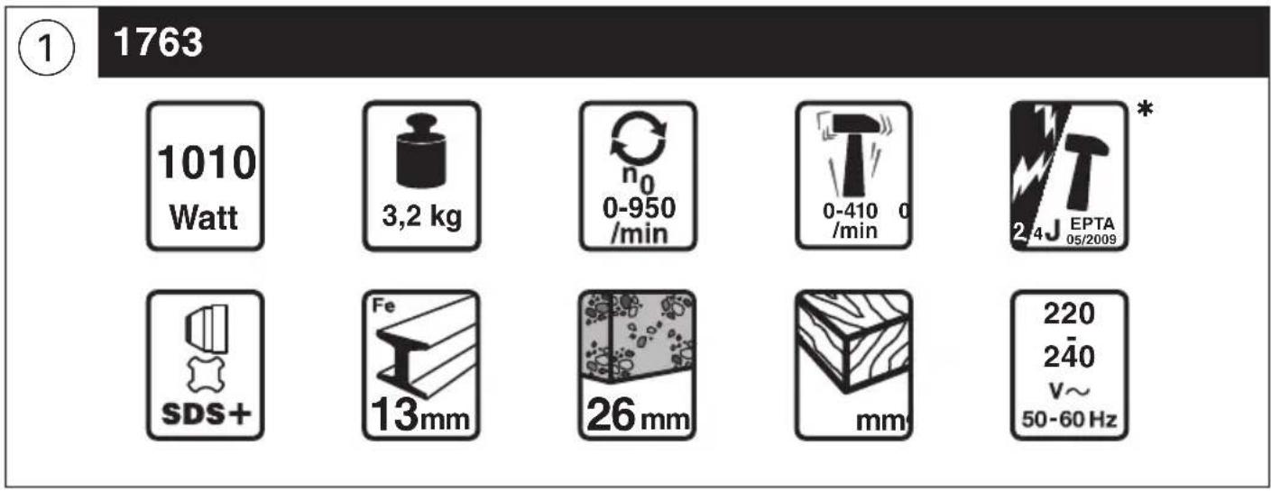
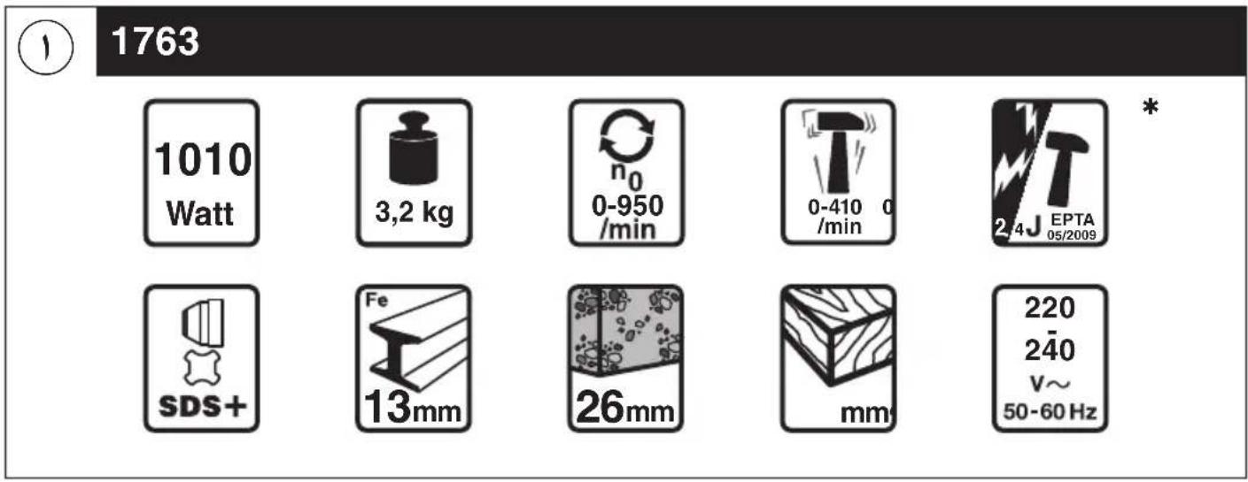
TECHNICAL DATA ①
*) Impact energy per stroke according to EPTA-Procedure 05/2009
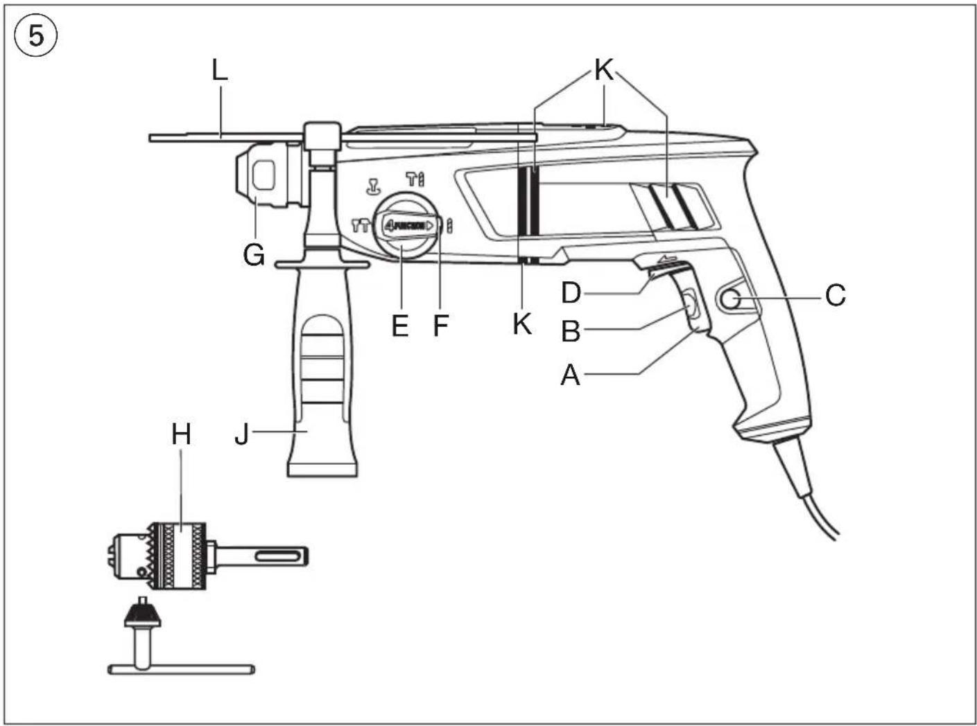
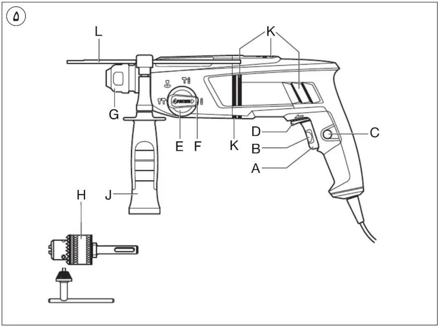
TOOL ELEMENTS ⑤
A Switch for on/off and speed control
B Wheel for maximum speed control
C Button for switch locking
D Lever for changing direction of rotation
E Switch for selecting operating mode
F Unlocking button
G Locking sleeve
H Adapter + 13 mm chuck
J Auxiliary handle
K Ventilation slots
L Depth gauge
SAFETY
GENERAL POWER TOOL SAFETY WARNINGS
WARNING Read all safety warnings, instructions, illustrations and specifications provided with this power tool. Failure to follow all instructions listed below may result in electric shock, fire and/or serious injury.
Save all warnings and instructions for future reference.
The term "power tool" in the warnings refers to your mains-operated (corded) power tool or battery-operated (cordless) power tool.
1) WORK AREA SAFETY
a) Keep work area clean and well lit. Cluttered or dark areas invite accidents.
b) Do not operate power tools in explosive atmospheres, such as in the presence of flammable liquids, gases or dust. Power tools create sparks which may ignite the dust or fumes.
c) Keep children and bystanders away while operating a power tool. Distractions can cause you to lose control.
2) ELECTRICAL SAFETY
a) Power tool plugs must match the outlet. Never modify the plug in any way. Do not use any adapter plugs with earthed (grounded) power tools.
Unmodified plugs and matching outlets will reduce risk of electric shock.
b) Avoid body contact with earthed or grounded surfaces such as pipes, radiators, ranges and refrigerators. There is an increased risk of electric shock if your body is earthed or grounded.
c) Do not expose power tools to rain or wet conditions. Water entering a power tool will increase the risk of electric shock.
d) Do not abuse the cord. Never use the cord for carrying, pulling or unplugging the power tool. Keep cord away from heat, oil, sharp edges or moving parts. Damaged or entangled cords increase the risk of electric shock.
e) When operating a power tool outdoors, use an extension cord suitable for outdoor use. Use of a cord suitable for outdoor use reduces the risk of electric shock.
f) If operating a power tool in a damp location is unavoidable, use a residual current device (RCD) protected supply. Use of an RCD reduces the risk of electric shock.
a) Stay alert, watch what you are doing and use common sense when operating a power tool. Do not use a power tool while you are tired or under the influence of drugs, alcohol or medication. A moment of inattention while operating power tools may result in serious personal injury.
b) Use personal protective equipment. Always wear eye protection. Protective equipment such as dust mask, non-skid safety shoes, hard hat, or hearing protection used for appropriate conditions will reduce personal injuries.
c) Prevent unintentional starting. Ensure the switch is in the off-position before connecting to power source and/or battery pack, picking up or carrying the tool. Carrying power tools with your finger on the switch or energising power tools that have the switch on invites accidents.
d) Remove any adjusting key or wrench before turning the power tool on. A wrench or a key left attached to a rotating part of the power tool may result in personal injury.
e) Do not overreach. Keep proper footing and balance at all times. This enables better control of the power tool in unexpected situations.
f) Dress properly. Do not wear loose clothing or jewellery. Keep your hair and clothing away from moving parts. Loose clothes, jewellery or long hair can be caught in moving parts.
g) If devices are provided for the connection of dust extraction and collection facilities, ensure these are connected and properly used. Use of dust collection can reduce dust-related hazards.
h) Do not let familiarity gained from frequent use of tools allow you to become complacent and ignore tool safety principles. A careless action can cause severe injury within a fraction of a second.
3) PERSONAL SAFETY
4) POWER TOOL USE AND CARE
a) Do not force the power tool. Use the correct power tool for your application. The correct power tool will do the job better and safer at the rate for which it was designed.
b) Do not use the power tool if the switch does not turn it on and off. Any power tool that cannot be controlled with the switch is dangerous and must be repaired.
c) Disconnect the plug from the power source and/or remove the battery pack, if detachable, from the power tool before making any adjustments, changing accessories, or storing power tools. Such preventive safety measures reduce the risk of starting the power tool accidentally.
d) Store idle power tools out of the reach of children and do not allow persons unfamiliar with the power tool or these instructions to operate the power tool. Power tools are dangerous in the hands of untrained users.
e) Maintain power tools and accessories. Check for misalignment or binding of moving parts, breakage of parts and any other condition that may affect the power tool's operation. If damaged, have the power tool repaired before use. Many accidents are caused by poorly maintained power tools.
f) Keep cutting tools sharp and clean. Properly maintained cutting tools with sharp cutting edges are less likely to bind and are easier to control.
g) Use the power tool, accessories and tool bits etc., in accordance with these instructions, taking into account the working conditions and the work to be performed. Use of the power tool for operations different from those intended could result in a hazardous situation.
h) Keep handles and grasping surfaces dry, clean and free from oil and grease. Slippery handles and grasping surfaces do not allow for safe handling and control of the tool in unexpected situations.
5) SERVICE
a) Have your power tool serviced by a qualified repair person using only identical replacement parts. This will ensure that the safety of the power tool is maintained.
SAFETY INSTRUCTIONS FOR HAMMERS
GENERAL
- Always check that the supply voltage is the same as the voltage indicated on the nameplate of the tool (tools with a rating of 230V or 240V can also be connected to a 220V supply)
- This tool should not be used by people under the age of 16 years
- Do not work materials containing asbestos (asbestos is considered carcinogenic)
- Never use the tool when cord is damaged; have it replaced by a qualified person
• Always disconnect plug from power source before making any adjustment or changing any accessory ACCESSORIES
- SKIL can assure flawless functioning of the tool only when original accessories are used
- Use only accessories with an allowable speed matching at least the highest no-load speed of the tool
BEFORE USE
- Use completely unrolled and safe extension cords with a capacity of 16 Amps (U.K. 13 Amps)
- Avoid damage that can be caused by screws, nails and other elements in your workpiece; remove them before you start working
- Secure the workpiece (a workpiece clamped with clamping devices or in a vice is held more securely than by hand)
- Use suitable detectors to find hidden utility lines or call the local utility company for assistance (contact with electric lines can lead to fire or electrical shock; damaging a gas line can result in an explosion; penetrating a water pipe will cause property damage or an electrical shock)
- Dust from material such as paint containing lead, some wood species, minerals and metal may be harmful (contact with or inhalation of the dust may cause allergic reactions and/or respiratory diseases to the operator or bystanders); wear a dust mask and work with a dust extraction device when connectable
- Certain kinds of dust are classified as carcinogenic (such as oak and beech dust) especially in conjunction with additives for wood conditioning; wear a dust mask and work with a dust extraction device when connectable
- Follow the dust-related national requirements for the materials you want to work with
DURING USE
- Wear ear protectors (exposure to noise can cause hearing loss)
- Use auxiliary handle(s), if supplied with the tool (loss of control can cause personal injury)
- Hold the power tool by insulated gripping surfaces, when performing an operation where the cutting accessory may contact hidden wiring or its own cord (cutting accessory contacting a “live” wire may make exposed metal parts of the power tool “live” and could give the operator an electric shock)
• Always keep the cord away from moving parts of the tool
- In case of electrical or mechanical malfunction, immediately switch off the tool and disconnect the plug
- If the cord is damaged or cut through while working, do not touch the cord, but immediately disconnect the plug
- If the drill bit becomes unexpectedly jammed (causing a sudden, dangerous reaction), immediately switch off the tool
- Be aware of the forces that occur as a result of jamming (especially when drilling metals); always use auxiliary handle J ^⑤ and take a secure stance
AFTER USE
- When you put away the tool, switch off the motor and ensure that all moving parts have come to a complete standstill
EXPLANATION OF SYMBOLS ON TOOL
② Read the instruction manual before use
③ Double insulation (no earth wire required)
④ Do not dispose of the tool together with household waste material
WHEN CONNECTING NEW 3-PIN PLUG (U.K. ONLY):
- Do not connect the blue (= neutral) or brown (= live) wire in the cord of this tool to the earth terminal of the plug
- If for any reason the old plug is cut off the cord of this tool, it must be disposed of safely and not left unattended
USE
- On/off ⑥
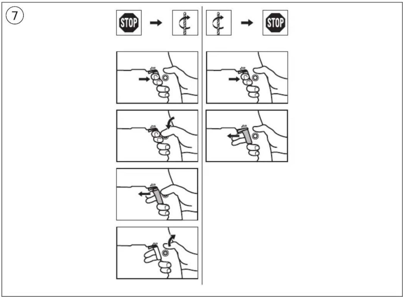
- Switch locking for continuous use ⑦
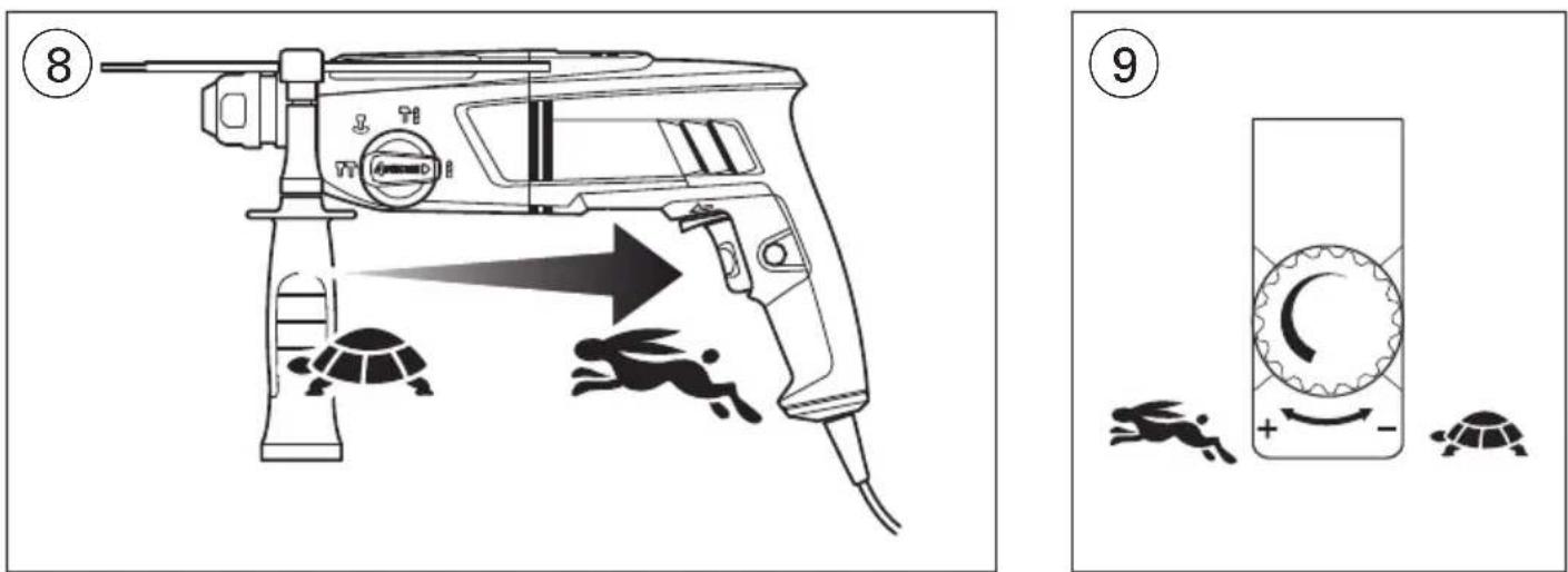
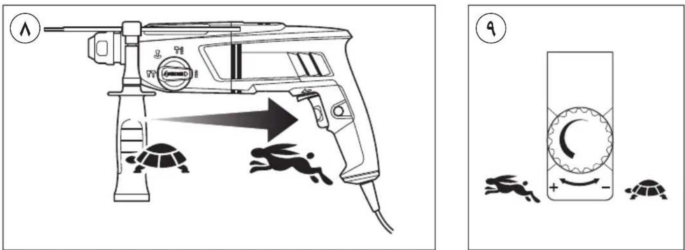
• Speed control for smooth starting ⑧
• Maximum speed control ⑨
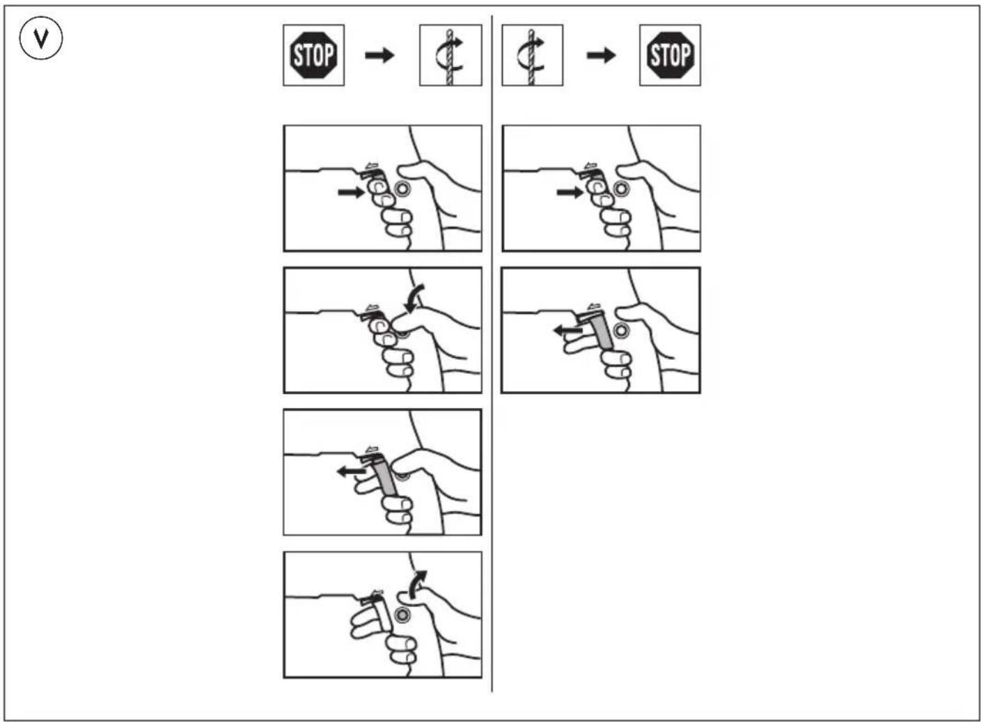
With wheel B ⑤ the maximum speed can be adjusted steplessly from minimum to maximum
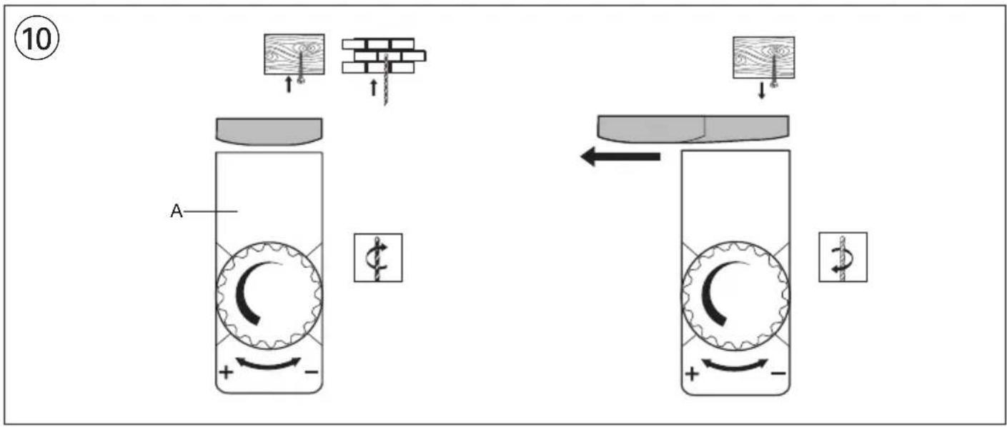
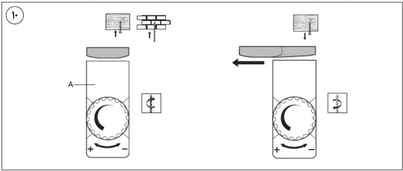
- Changing direction of rotation ⑩
- when not properly set in left/right position, switch A cannot be activated
! change direction of rotation only when tool is at a complete standstill
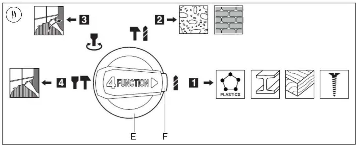
- Selecting operating mode ⑪
- press button F to unlock switch E
- turn switch E to the desired operating mode until it snap-locks
! start working only when switch E is locked
1 = normal drilling/screwdriving
2 = impact drilling
3 = chiseling with rotating chisel
4 = chiseling with fixed chisel
! select operating mode only when tool is switched off and plug is disconnected
- the hammer mechanism is activated by applying a slight pressure on the tool when the drill bit is in contact with the workpiece
- best hammer drilling results can be obtained by only a slight pressure on the tool; drilling performance will not improve by applying more pressure on the tool
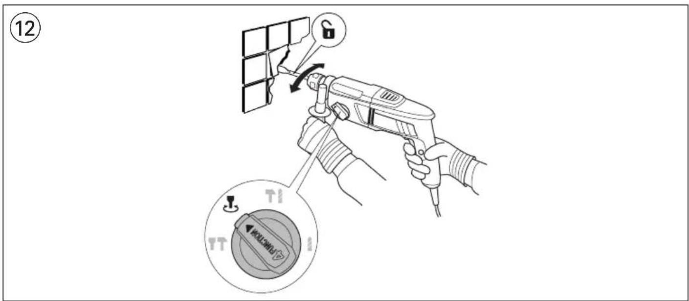
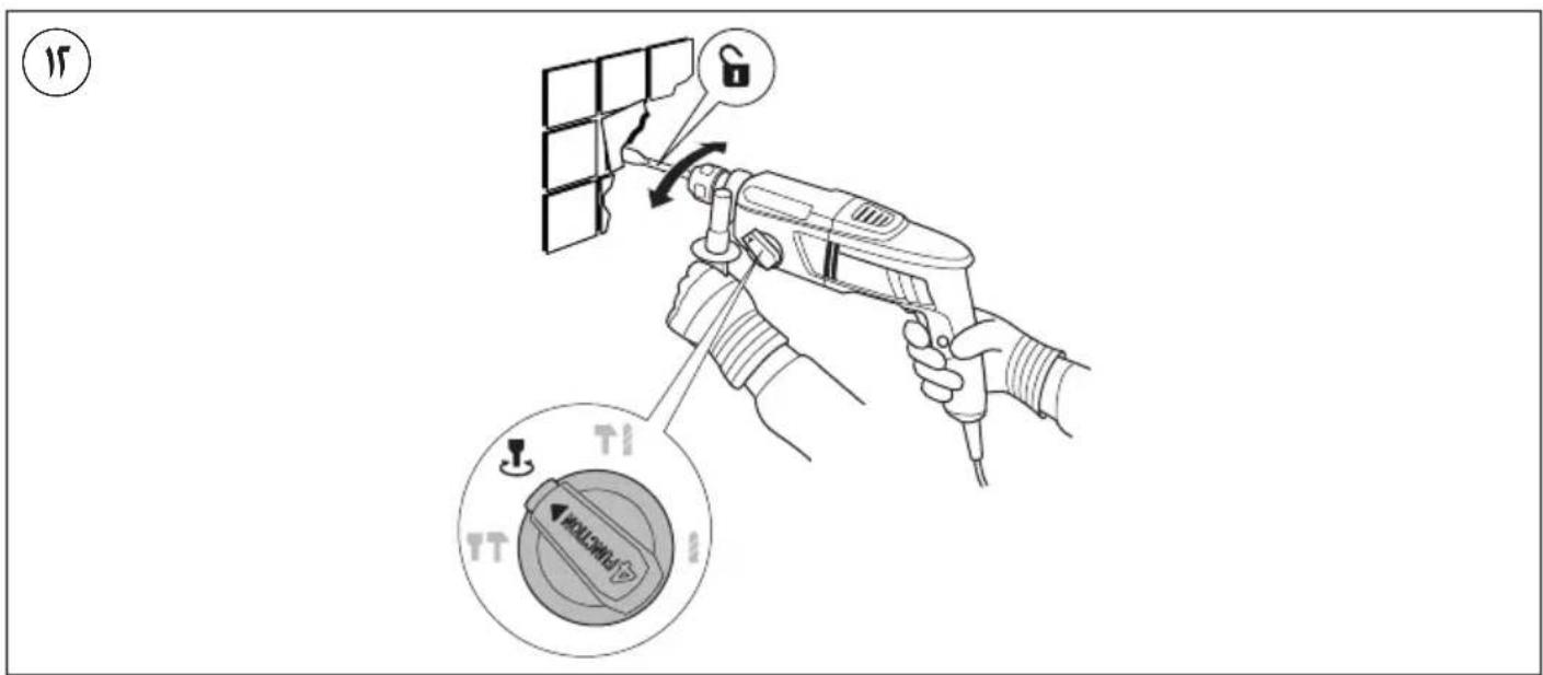
• Chiseling with rotating chisel ⑫
! switch off the tool and disconnect the plug
- select "rotating" chiseling mode
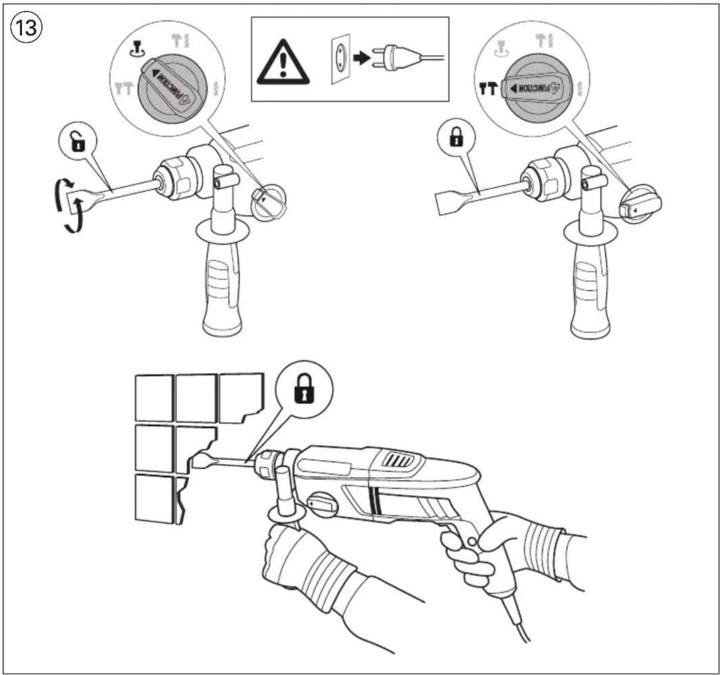
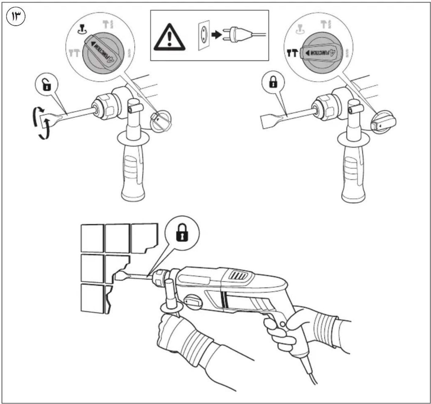
• Chiseling with fixed chisel ⑬
! switch off the tool and disconnect the plug
- select "rotating" chiseling mode
- place chisel in desired position
- select "fixed" chiseling mode
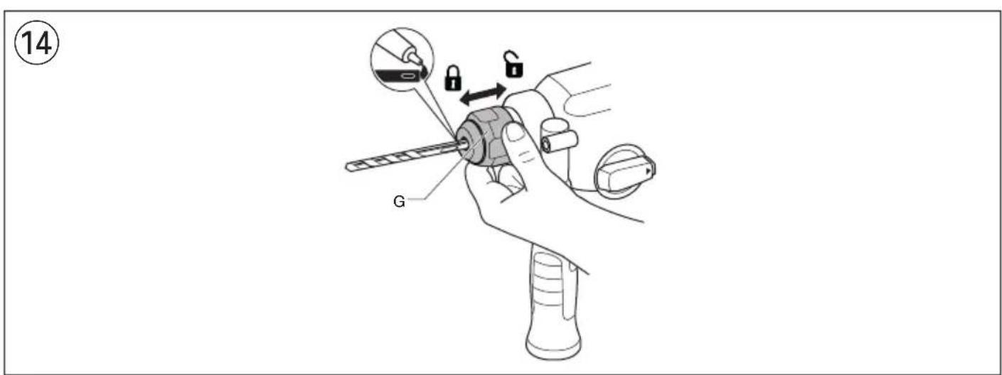
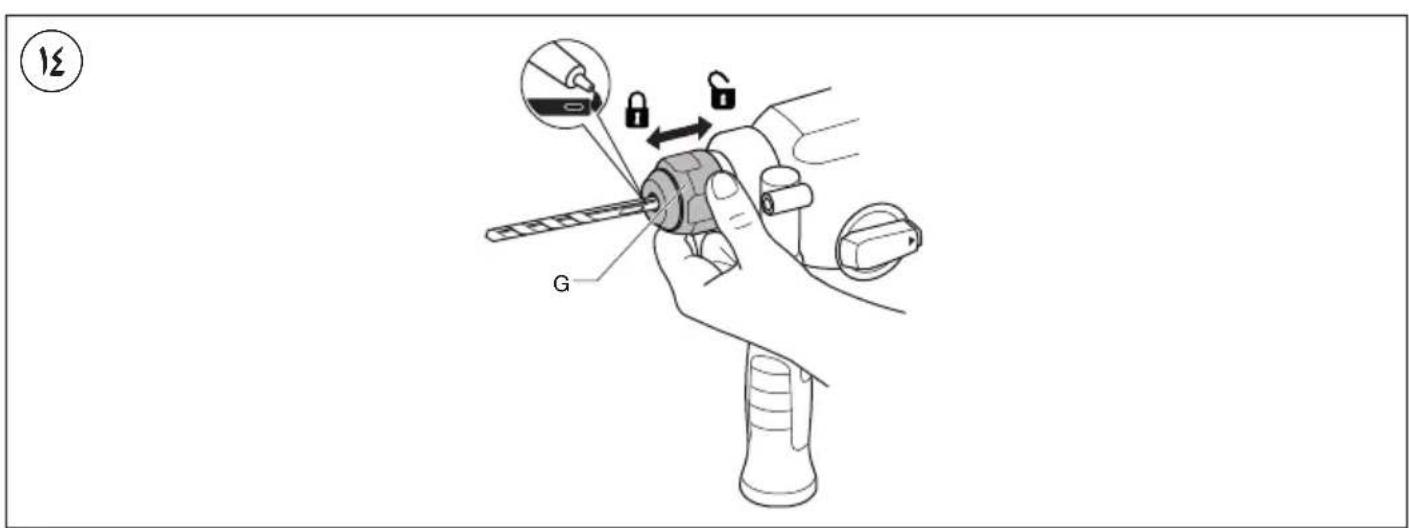
- Changing bits ⑭
! clean and lightly lubricate the SDS+ accessory before insertion
- pull back locking sleeve G and insert accessory in SDS+ chuck while turning and pushing it until it engages; the accessory locks in position automatically
- pull accessory to check that it is locked correctly
- remove accessory by pulling back locking sleeve G
! the SDS+ accessory requires freedom of movement which causes eccentricity when tool is off-load; however, the accessory automatically centres itself during operation without affecting drilling precision
! do not use bits/chisels with a damaged shank
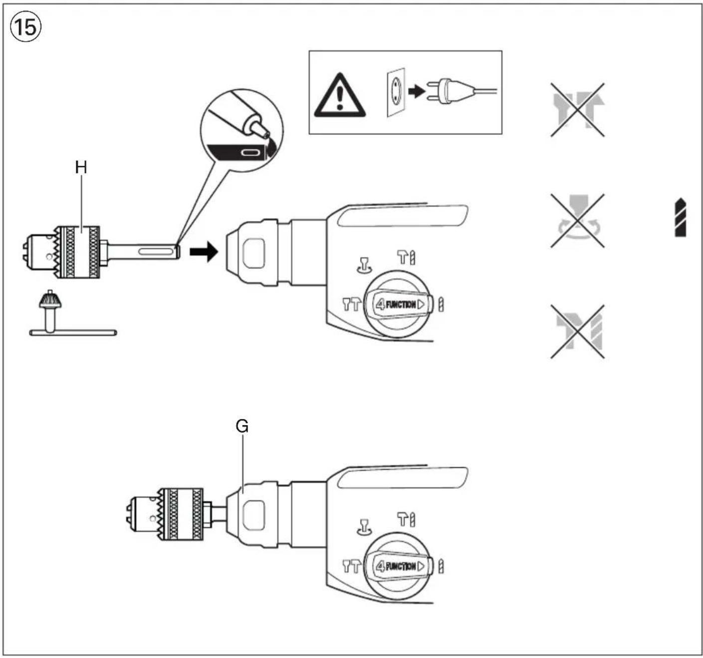
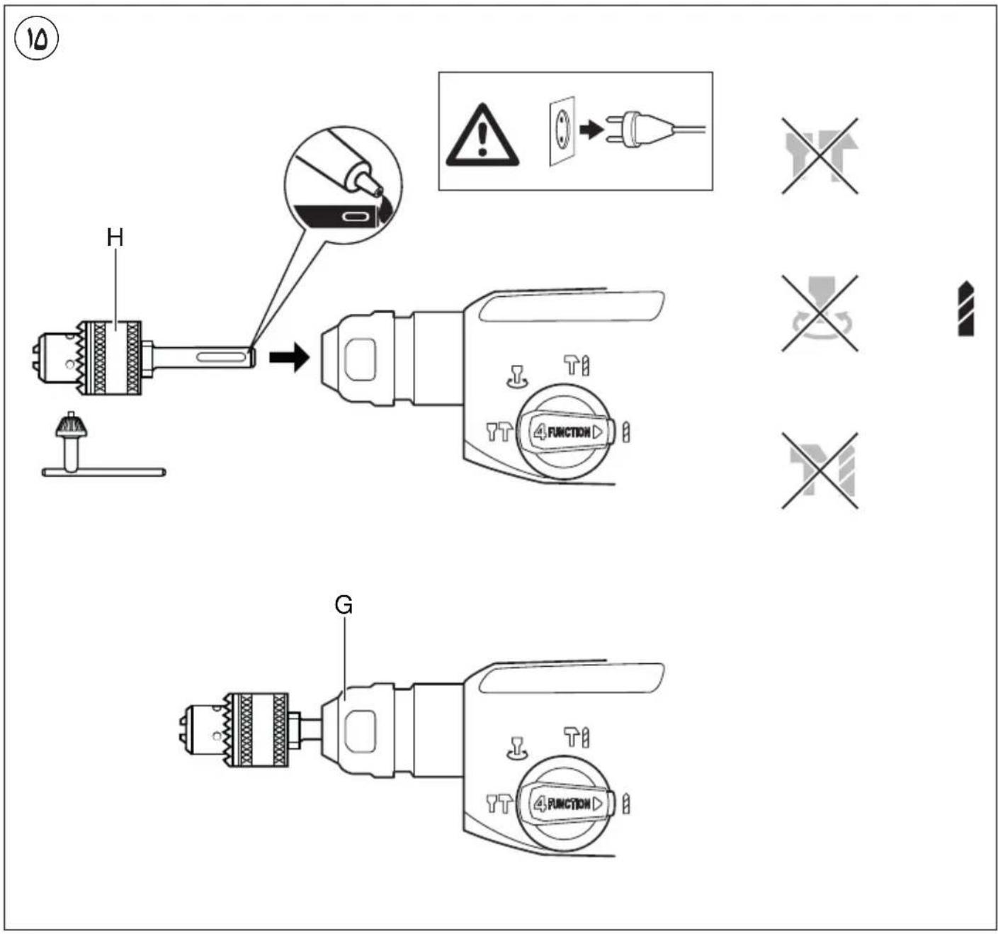
For drilling in wood, metal and plastic as well as for screwdriving use adapter H ^15
- clean and lightly lubricate adapter before insertion
- pull back locking sleeve G and insert adapter in SDS+ chuck while turning and pushing it until it engages; the adapter locks in position automatically
- pull adapter to check whether is it locked correctly
- set switch E ⑤ to normal drilling (only activate when tool is switched off and plug is disconnected)
- Safety clutch
If the accessory gets jammed, the drive to the spindle is interrupted (causing a rattling noise)
- immediately switch off tool
- remove the jammed accessory
- switch on tool again
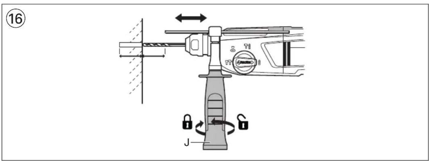
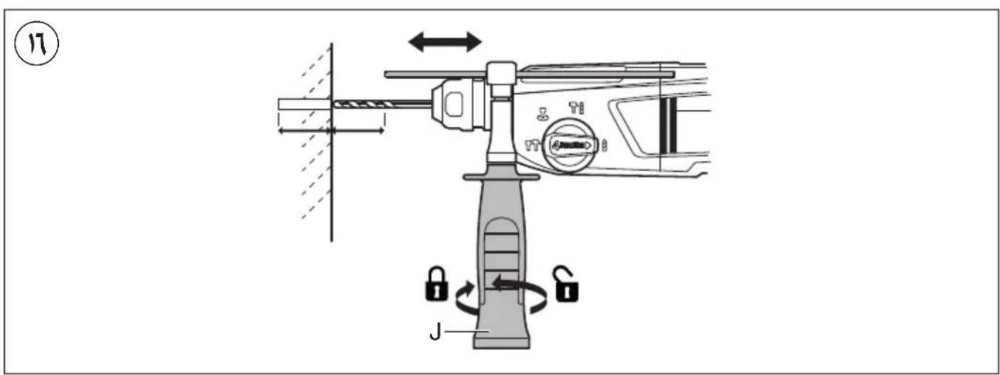
- Adjusting drilling depth ⑯
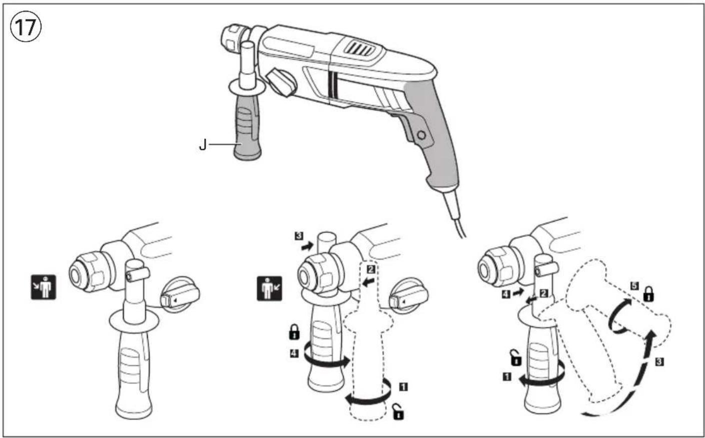
• Holding and guiding the tool ⑰
! while working, always hold the tool at the grey-coloured grip area(s)
- always use auxiliary handle J (can be adjusted as illustrated)
- keep the ventilation slots uncovered
- do not apply too much pressure on the tool; let the tool do the work for you
APPLICATION ADVICE
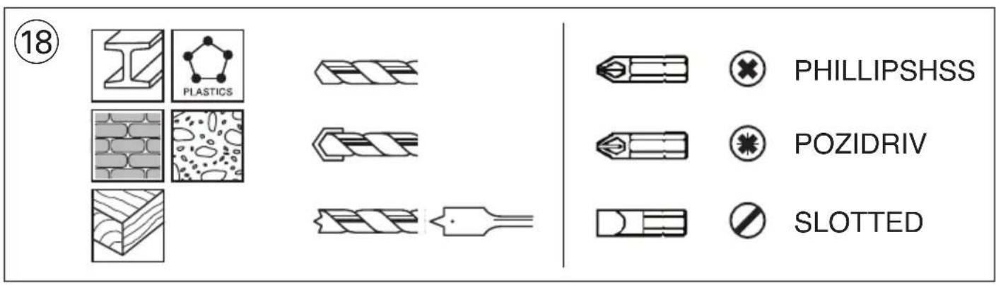
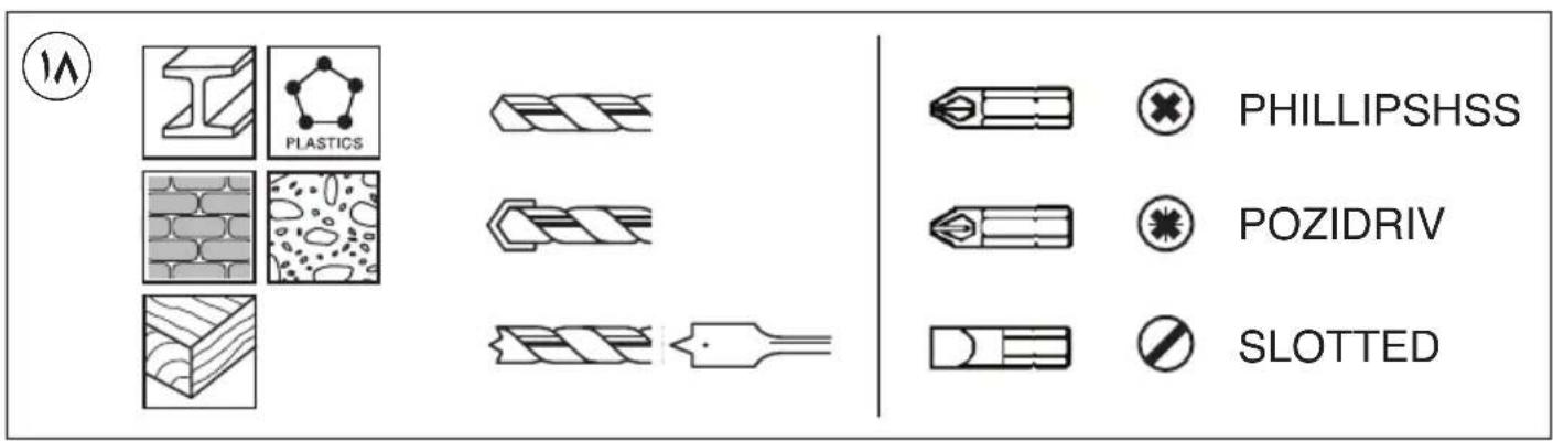
- Use the appropriate bits ⑱
! only use sharp bits/chisels - When drilling ferrous metals
- pre-drill a smaller hole, when a large hole is required
- lubricate drill bit occasionally with oil
- When turning in a screw at/near the cross cut end or an edge of wood, pre-drill a hole in order to avoid cracking of the wood
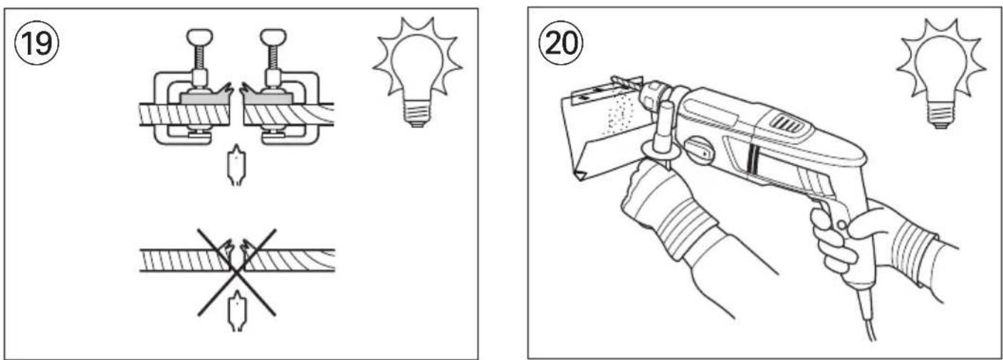
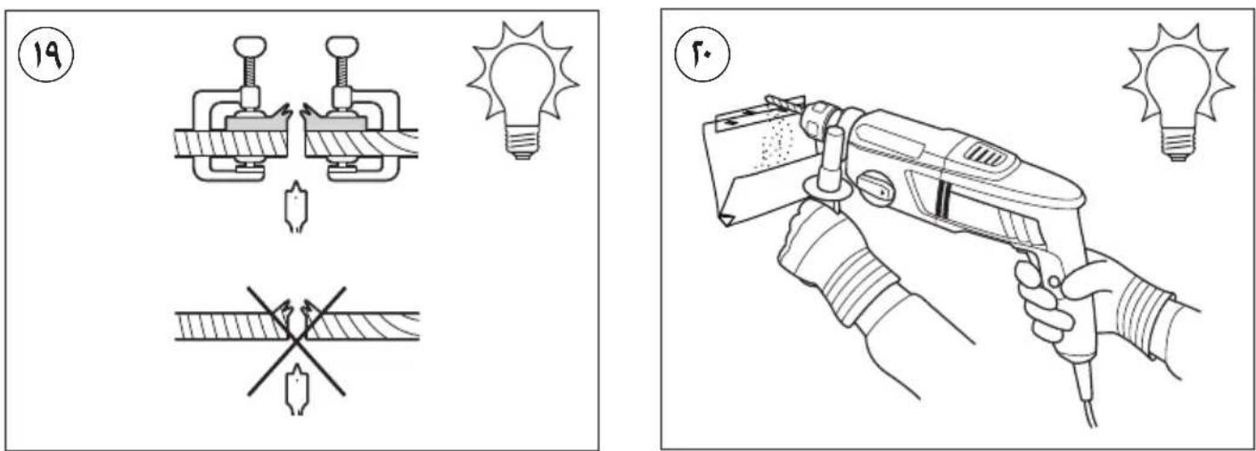
- Splinterfree drilling in wood ⑲
• Dustfree drilling in walls 20
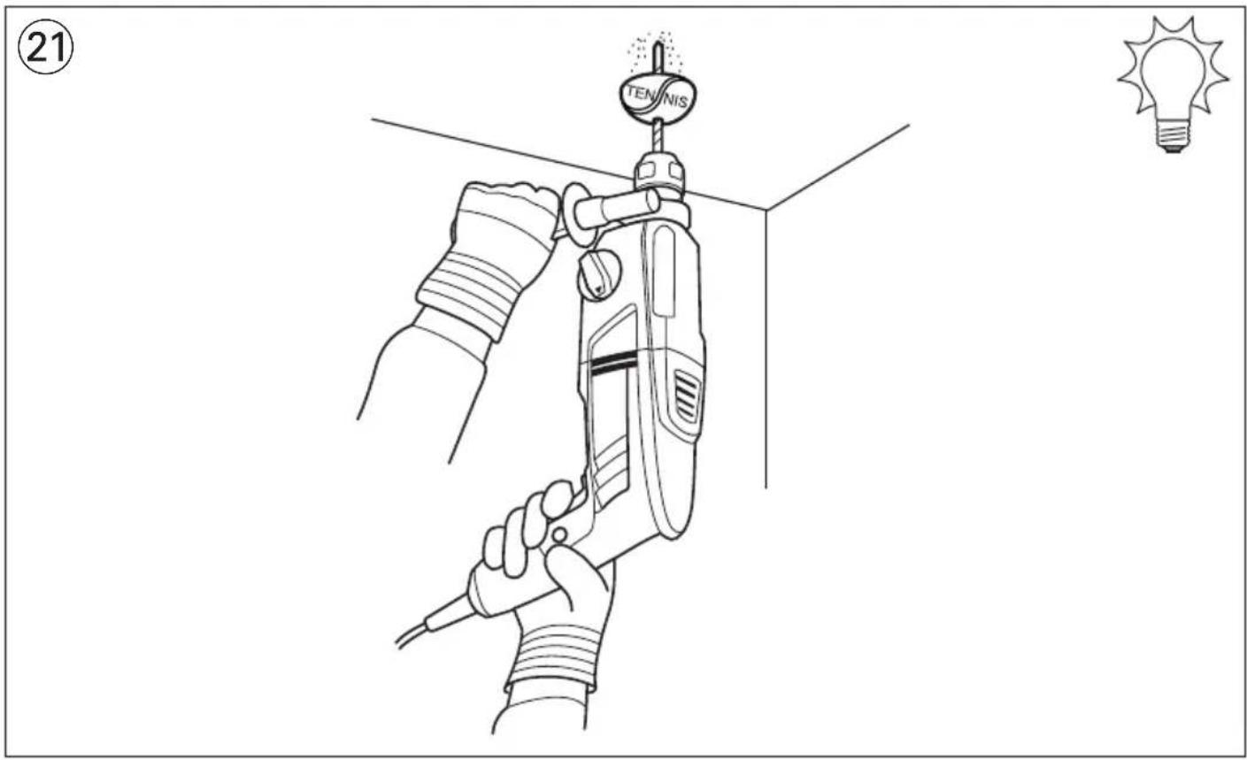
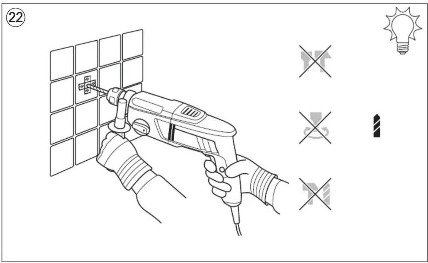
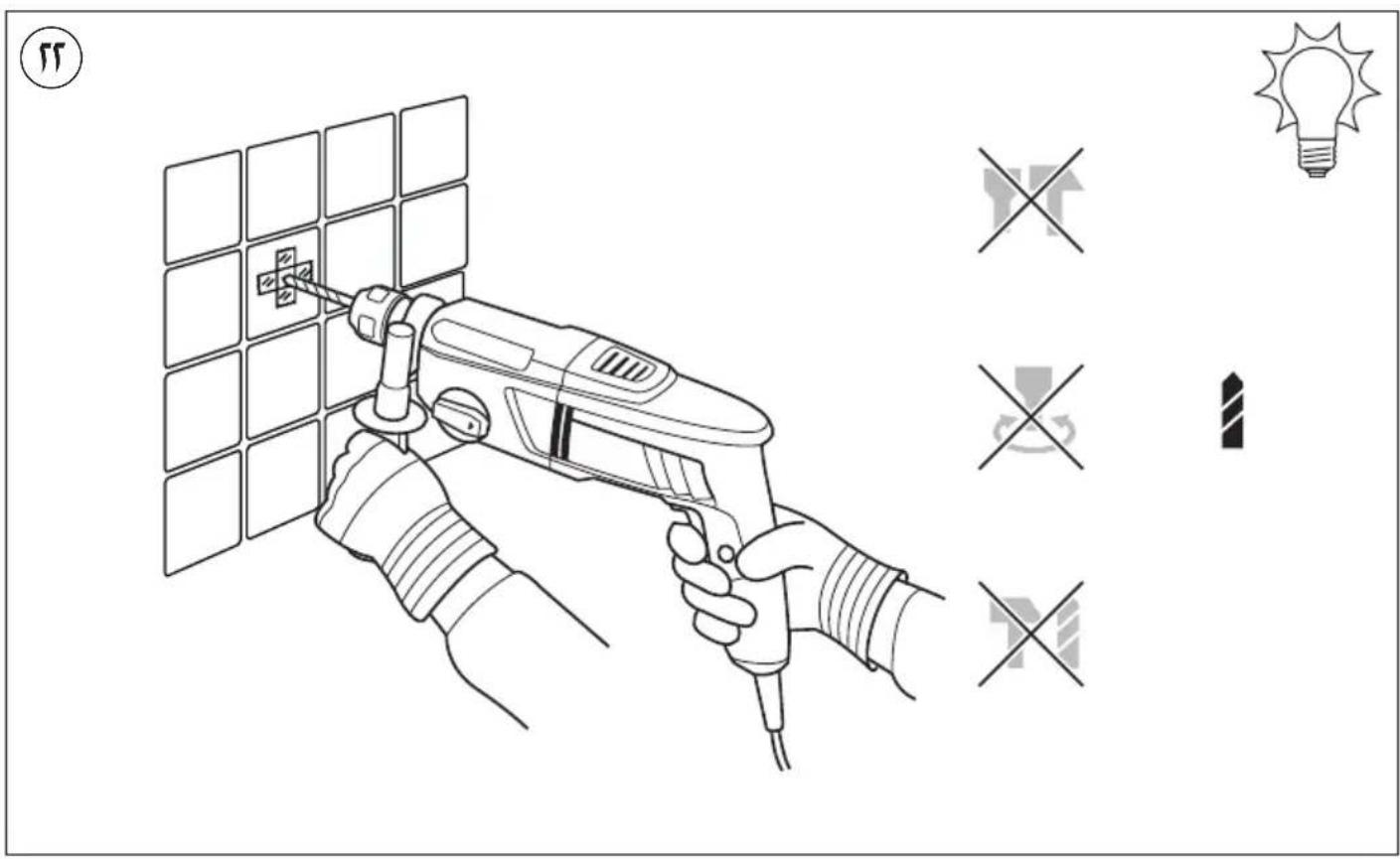
• Dustfree drilling in ceilings ②1 - Drilling in tiles without skidding ②
- For more tips see www.skil.com
MAINTENANCE / SERVICE
• This tool is not intended for professional use
- Always keep tool and cord clean (especially ventilation slots K ⑤)
! disconnect the plug before cleaning
- If the tool should fail despite the care taken in manufacturing and testing procedures, repair should be carried out by an after-sales service centre for SKIL power tools
- send the tool undismantled together with proof of purchase to your dealer or the nearest SKIL service station (addresses as well as the service diagram of the tool are listed on www.skil.com)
ENVIRONMENT
- Do not dispose of electric tools, accessories and packaging together with household waste material (only for EU countries)
- in observance of European Directive 2012/19/EC on waste of electric and electronic equipment and its implementation in accordance with national law, electric tools that have reached the end of their life
must be collected separately and returned to an environmentally compatible recycling facility
- symbol ④ will remind you of this when the need for disposing occurs
NOISE / VIBRATION
- Measured in accordance with EN 60745 the sound pressure level of this tool is 91.0 dB(A) and the sound power level 102.0 dB(A) (standard deviation: 3 dB), and the vibration * (triax vector sum; uncertainty K = 1.5 m/s^2 )
* when hammer drilling in concrete 12.3 m/s²
* when chiseling 10.9 m/s ^2
- The vibration emission level has been measured in accordance with a standardised test given in EN 60745; it may be used to compare one tool with another and as a preliminary assessment of exposure to vibration when using the tool for the applications mentioned
- using the tool for different applications, or with different or poorly maintained accessories, may significantly increase the exposure level
- the times when the tool is switched off or when it is running but not actually doing the job, may significantly reduce the exposure level
! protect yourself against the effects of vibration by maintaining the tool and its accessories, keeping your hands warm, and organizing your work patterns
F
WAARSCHUWING Lees alle
1 = normal borning/skruvdragning
2 = slagborrning
1) SIKKERHET PÅ ARBEIDSPLASSEN
1 = normal boring/skruing
2 = slagboring
3 = meisling med den roterende meiselen
4 = meisling med den faste meiselen
VEDLIKEHOLD / SERVICE
APKALPOŠANA / APKOPE
TECHNINIAI DUOMENYS ①
*) Smūgio energija pagal EPTA-Procedure 05/2009
PRIETAISO ELEMENTAI ⑤

flowchart
graph LR
    A["Raw Materials"] --> B["Step 2: Material Manufacturing"]
    B --> C["Intermediate Product"]
    C --> D["Step 1: Plastics"]
    D --> E["Final Product"]
    subgraph Process Steps
        F["Step 3: Raw Material & Material Structure"] --> G["Step 2: Material Production & Material Use"]
        H["Step 4: Material Fabric & Material Structure"] --> I["Step 4: Material Production & Material Use"]
        J["Step 5: Material Fabric & Material Structure"] --> K["Step 4: Material Production & Material Use"]
        L["Step 6: Material Fabric & Material Structure"] --> M["Step 4: Material Production & Material Use"]
        N["Step 7: Material Fabric & Material Structure"] --> O["Step 4: Material Production & Material Use"]
        P["Step 8: Material Fabric & Material Structure"] --> Q["Step 4: Material Production & Material Use"]
        R["Step 9: Material Fabric & Material Structure"] --> S["Step 4: Material Production & Material Use"]
        T["Step 10: Material Fabric & Material Structure"] --> U["Step 4: Material Production & Material Use"]
        V["Step 11: Material Fabric & Material Structure"] --> W["Step 4: Material Production & Material Use"]
        X["Step 12: Material Fabric & Material Structure"] --> Y["Step 4: Material Production & Material Use"]
        Z["Step 13: Material Fabric & Material Structure"] --> AA["Step 4: Material Production & Material Use"]
        AB["Step 14: Material Fabric & Material Structure"] --> AC["Step 4: Material Production & Material Use"]
        AD["Step 15: Material Fabric & Material Structure"] --> AE["Step 4: Material Production & Material Use"]
        AF["Step 16: Material Fabric & Material Structure"] --> AG["Step 4: Material Production & Material Use"]
        AH["Step 17: Material Fabric & Material Structure"] --> AI["Step 4: Material Production & Material Use"]
        AJ["Step 18: Material Fabric & Material Structure"] --> AK["Step 4: Material Production & Material Use"]
        AL["Step 19: Material Fabric & Material Structure"] --> AM["Step 4: Material Production & Material Use"]
        AN["Step 20: Material Fabric & Material Structure"] --> AO["Step 4: Material Production & Material Use"]
        AP["Step 21: Material Fabric & Material Structure"] --> AQ["Step 4: Material Production & Material Use"]
        AR["Step 22: Material Fabric & Material Structure"] --> AS["Step 4: Material Production & Material Use"]
        AT["Step 23: Material Fabric & Material Structure"] --> AU["Step 4: Material Production & Material Use"]
        AV["Step 24: Material Fabric & Material Structure"] --> AW["Step 4: Material Production & Material Use"]
        AX["Step 25: Material Fabric & Material Structure"] --> AY["Step 4: Material Production & Material Use"]
        AZ["Step 26: Material Fabric & Material Structure"] --> BA["Step 4: Material Production & Material Use"]
        BB["Step 27: Material Fabric & Material Structure"] --> BC["Step 4: Material Production & Material Use"]
        BD["Step 28: Material Fabric & Material Structure"] --> BE["Step 4: Material Production & Material Use"]
        BF["Step 29: Material Fabric & Material Structure"] --> BG["Step 4: Material Production & Material Use"]
        BH["Step 30: Material Fabric & Material Structure"] --> BI["Step 4: Material Production & Material Use"]
        BJ["Step 31: Material Fabric & Material Structure"] --> BK["Step 4: Material Production & Material Use"]
        BL["Step 32: Material Fabric & Material Structure"] --> BM["Step 4: Material Production & Material Use"]
        BN["Step 33: Material Fabric & Material Structure"] --> BO["Step 4: Material Production & Material Use"]
        BP["Step 34: Material Fabric & Material Structure"] --> BQ["Step 4: Material Production & Material Use"]
        BR["Step 35: Material Fabric & Material Structure"] --> BS["Step 4: Material Production & Material Use"]
        BT["Step 36: Material Fabric & Material Structure"] --> BU["Step 4: Material Production & Material Use"]
        BV["Step 37: Material Fabric & Material Structure"] --> BW["Step 4: Material Production & Material Use"]
        BX["Step 38: Material Fabric & Material Structure"] --> BY["Step 4: Material Production & Material Use"]
        BZ["Step 39: Product Fabric & Packaging"] --> CA["Step 4: Product Fabric & Packaging"]
    end

flowchart
graph TD
    A["STOP"] --> B["Arrow to Arrow"]
    B --> C["Arrow to Arrow"]
    C --> D["STOP"]

natural_image
Illustration of a black-and-white photo of a four-function drill bit (no text or symbols visible)


- CE
- 1763
- GB
- Rotary hammer 1763
- INTRODUCTION
- TECHNICAL DATA ①
- TOOL ELEMENTS ⑤
- SAFETY
- GENERAL POWER TOOL SAFETY WARNINGS
- 1) WORK AREA SAFETY
- 2) ELECTRICAL SAFETY
- 3) PERSONAL SAFETY
- 4) POWER TOOL USE AND CARE
- 5) SERVICE
- SAFETY INSTRUCTIONS FOR HAMMERS
- GENERAL
- BEFORE USE
- DURING USE
- AFTER USE
- EXPLANATION OF SYMBOLS ON TOOL
- WHEN CONNECTING NEW 3-PIN PLUG (U.K. ONLY):
- USE
- APPLICATION ADVICE
- MAINTENANCE / SERVICE
- ENVIRONMENT
- NOISE / VIBRATION
- F
- WAARSCHUWING Lees alle
- 1) SIKKERHET PÅ ARBEIDSPLASSEN
- VEDLIKEHOLD / SERVICE
- APKALPOŠANA / APKOPE
- TECHNINIAI DUOMENYS ①
- PRIETAISO ELEMENTAI ⑤
Brand : SKIL
Model : 1763 AK
Category : Hammer