
KSS 300 - Saw Mafell - Free user manual and instructions
Find the device manual for free KSS 300 Mafell in PDF.

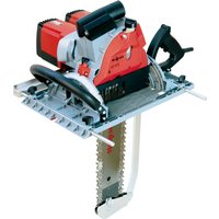
| Product type | Portable circular saw / Cross-cutting system |
| Brand | Mafell |
| Model | KSS 300 |
| Service voltage | 230 V AC / 110 V AC |
| Mains frequency | 50 Hz |
| Continuous power consumption | 900 W (230 V) / 1000 W (110 V) |
| No-load speed | 8800 min⁻¹ |
| Cutting depth (0°) | 42 mm |
| Cutting depth (45°) | 29 mm |
| Max/min blade diameter | 120 mm / 112 mm |
| Blade arbor | 20 mm |
| Weight (without cable and parallel guide) | 2.3 kg |
| Dimensions (with guide device) | 200 x 550 x 200 mm |
| Sound level (LWA) | 103 dB(A) |
| Hand-arm vibration | < 2.5 m/s² |
| Safety devices | Fixed upper protective guard, movable lower protective guard, large base plate, handles, riving knife, control and brake device, extraction hose |
| Standard equipment | 1 carbide blade 120 mm 40 teeth, 1 riving knife, 1 extraction sleeve, 1 parallel guide, 1 service tool, 1 transport case, 1 instruction manual, 1 safety instructions booklet, 2 clamping claws, 1 FLEXI FX 140 rail |
| Intended use | Longitudinal and cross cutting of solid wood, wood-based panels, wood fiber insulation materials and plastics (polystyrene) |
| Care and maintenance | Regular cleaning, use of original Mafell spare parts, overhaul by Mafell after-sales service after long use |
Frequently Asked Questions - KSS 300 Mafell
User questions about KSS 300 Mafell
0 question about this device. Answer the ones you know or ask your own.
Ask a new question about this device
Download the instructions for your Saw in PDF format for free! Find your manual KSS 300 - Mafell and take your electronic device back in hand. On this page are published all the documents necessary for the use of your device. KSS 300 by Mafell.
USER MANUAL KSS 300 Mafell
Portable circular saw / cross-cutting system
Translation of the original 18 operating instructions
Please read all safety instructions and directions. Failure to comply with the safety instructions and directions can cause electric shock, fire and/or serious injuries. Please retain all safety instructions and directions for future reference.
AVERTISSEMENT
GB-EC Declaration of Conformity
We herewith confirm that the machine KSP 40 FLEXISTEM complies with the EU directives quoted. The standards listed were used for design and construction. Empowered person for the configuration of the technical documents: Malell AG
CZ - PROHLASENI O SHODE
Timo prohlajeme, ze stroj KSP 40 FLEXITEM splnue pkony uvedenych smemic EU. Pfn pnanovani a sestaveni byly vy uyizy uvedene normy. Za sestaveni technickych podkladu zodpovida. Mafell AG
SLO - ES izjava o skladnosti
S tem izavjamo, da stroj KSP 40 FLEXITEM ustreza navenedenim dirktivam EU. Pri konstrukcij in Izdelavi so uporabljeni naštei standardi Za sestavo tehnicih documentsace je pooblašeno podjefe: Mafel AG
SVK - Vyhlaseienie o zhode
Tymto potvrduzjeme, ze stroq KSP 40 FLEXISTEM zodpoveda uvedenym smemiciam EU. Pri projektovani a stavbe boli pouzite normy uvedene v zozyme. Osoba poverená vyhotovenim technickych podkladov: Mafell AG

2006/42/EG
2014/30/EU
2011/65/EU
KSP 40 FLEXISTEM
EN62841-1,EN62841-2-5,EN55014-1,EN55014-2
EN IEC 61000-3-2, EN 61000-3-3, EN ISO 12100, EN 847-1
Mafell AG
Befiendorfer Str. 4
GB - EC Declaration of Conformity
We herewith confirm that the machine KSS 300 complies with the EU directives quoted. The standards listed were used for design and construction. Empowered person for the configuration of the technical documents: Mafell AG
CZ - PROHLASENI O SHODE
Timo prohaujeme, ze stroj KSS 300 spluije pouky uvedenych smemic EU. Pn planovani a sestaveni byly vyuzity uvedene normy. Za sestaveni technickych podkladu zodpovidla Mafell AG
SLO - ES izjava o skladnostl
S tem izavjamo, da stroj KSS 300 ustreza navedenim direktivam EU. Pri konstrukcij in izdelavi so uporabljeni našeti standardi. Za sestavo tehnlice dokumentaci je pooblašeno podje: Mafell AG
SVK - Vyhlasonie o zhode
Tymto potvrzujeme, ze stroj KSS 300 zodpoveda uvedenym smemiciam EU. Pri projektovani a stavbe boli pouzite normy uvedene v zozname. Osobe poverené vyhotovenim technickych podkiadov. Mafeil AG

2006/42/EG
2014/30/EU
2011/65/EU
KSS 300
Mafell AG
Beffendorfer Str. 4
$$ P A = 3, 0 \mathrm {d B} (A) $$
1 Signs and symbols 19
2 Product information 19
2.1 Manufacturer's data 19
2.2 Machine identification 19
2.3 Technical data 20
2.4 Emissions 20
2.5 Scope of supply 21
2.6 Safety devices 22
2.7 Use according to intended purpose 22
2.8 Residual risks 22
3 Safety instructions 22
4 Setting/Adjustment 24
4.1 Mains connection 24
4.2 Chip extraction 24
4.3 Sawblade selection 24
4.4 Sawblade change 25
4.5 Riving knife/splitter 25
5 Operation 25
5.1 Initial operation 25
5.2 Switching on and off 25
5.3 Cutting depth adjustment 25
5.4 Setting for bevel cuts 26
5.5 Plunge cuts 26
5.6 Sawing with FLEXI rail 26
5.7 Sawing shadow gaps 26
5.8 Sawing with the parallel stop 26
5.9 Sawing according to tracings 27
6 Service and maintenance 27
6.1 Storage 27
7 Troubleshooting 27
8 Optional accessories 28
9 Exploded drawing and spare parts list 28
1 Signs and symbols

This symbol is found in all places where you will find information for your safety.
Non-compliance with these instructions may result in very serious injuries.
This symbol indicates a potentially hazardous situation.
If this situation is not avoided, the product or objects in its vicinity may get damaged.

This symbol indicates tips for the user and other useful information.
2 Product information
KSP 40 Flexistem: Art.-No. 915801, 915820, 915825
KSS 300: Art.-No. 916701, 916702, 916720, 916725, 916730, 916731, 916732, 916735
2.1 Manufacturer's data
MAFELL AG, Beffendorfer Straße 4, D-78727 Oberndorf / Neckar, Phone +49 (0)7423/812-0, Fax +49 (0)7423/812-218, e-mail: mafell@mafell.de
2.2 Machine identification
All details required for machine identification are available on the attached rating plate.

Protection class II

CE symbol to document compliance with the basic safety and health requirements according to Appendix I of the Machinery Directive.

For EU countries only
Do not dispose of electric tools together with household waste material!
In accordance with the European directive 2002/96/EC on waste electrical and electronic equipment and transposition into national law, obsolete electrical tools must be collected separately and recycled in an environmentally-compatible manner.

To reduce the risk of injury, please read the operating instructions.
2.3 Technical data
KSP 40 Flexistem
Operating voltage
Mains frequency
Input power continuous operation
Power consumption continuous operation
Speed during idling
Cutting depth 0° / 30° / 45°
Swivelling saw unit
Saw blade diameter max/min
Saw blade body thickness
Tool cutting width
Saw blade mounting hole
Hose connector diameter
Weight without mains cable, without parallel guide fence
Dimensions (W× L× H)
230VAC 110VAC
50 Hz 50 Hz
900W 1000W
4,1A 9,1A
8800 rpm
42/36/29 mm (1 21/32, 1 27/64, 1 9/64
in.)
0 - 45°
120/112 mm (4 47/64, 4 13/32 in.)
1.2 mm (3/64 in.)
1,8 mm (5/64 in.)
20 mm
28 mm ( 1 7/64 in.)
2,2 kg (4.8 lbs)
181×306×199mm(71/8×12×7
13/16 in.)
KSS 300
Operating voltage
Mains frequency
Input power continuous operation
Power consumption continuous operation
Speed during idling
Cutting depth 0° / 45°
Tilting saw unit
Saw blade diameter max/min
Largest thickness basic saw blade body
Tool cutting width
Saw blade mounting hole
Hose connector diameter
Weight without mains cable, without parallel guide fence
Dimensions incl. guiding device (W× L× H)
230 V AC 110 V AC
50 Hz 50 Hz
900W 1000W
4,1A 9,1A
8800 rpm
42/29 mm ( 1 21/32, 1 9/64 in.)
0 - 45°
120/112 mm (4 23/32, 4 13/32 in.)
1.2 mm (3/64 in.)
1.8 mm (5/64 in.)
20 mm
28 mm ( 1 7/64 in.)
2.3 kg (5.07 lbs)
200 × 550 × 200 mm (77/8 × 2121/32 ×
7 7/8 in.)
as cross-cutting system
Cutting depth 0° / 45°
Cutting length at 12/40 mm (12 / 1 12. in.) workpiece thickness
Weight with guiding device, without mains cable
40/27 mm (1 9/16, 1 1/16 in.)
337/292 mm (13 1/4, 11 1/2 in.)
3,0 kg (3.0 lbs)
2.4 Emissions
The declared noise emission values have been measured in accordance with EN 62841-1 and EN 62841-2-5 and may be used for comparing the tool with another and also in a preliminary assessment of exposure.

Danger
The noise emissions during actual use of the power tool can differ from the declared values depending on the ways in which the tool is used especially what kind of workpiece is processed.
Always wear hearing protection, even when the power toolist running idle in addition to the trigger time!
2.4.1 Noise emission specifications
Noise emission values determined according to EN 62841-1 and EN 62841-2-5:
Sound pressure level L
$$ P A = 9 5 \mathrm {d B} (\mathrm {A}) $$
Uncertainty
$$ \mathrm {K P A} = 3. 0 \mathrm {d B} (\mathrm {A}) $$
Sound power level L
$$ \mathrm {P A} = 1 0 3 \mathrm {d B} (\mathrm {A}) $$
Uncertainty K
$$ P A = 3, 0 \mathrm {d B} (A) $$
The noise measurement was recorded using the saw blade included in the standard equipment.
2.4.2 Vibration specifications
The typical hand-arm vibration is less than 2.5m / s2
2.5 Scope of supply
Portable circular saw KSP 40 Flexistem complete with:
1 carbide tipped circular saw blade 120mm , 24 teeth
1 riving knife/splitter (thickness 1.2mm / 3 / 64 in.)
1 hose connector
1 parallel stop
1 service tool in bracket on the machine
1 carrying case Max
1 operating manual
1 folder "Safety instructions"
2 clamping claws
1 FLEXI rail FX 140 for cutting length max. 140cm (55 in.)
Cross-cutting system KSS 300 complete with:
1 carbide-tipped circular saw blade 0 120 mm ( 4 34 in. ) , 40 teeth
1 riving knife / splitter (thickness 1.2 mm / 3/64 in.)
1 hose connector
1 parallel guide fence
1 service tool in bracket on the machine
1 carrying case max
1 operating manual
1 folder "Safety Instructions"
2 clamping claws on item No. 916702, 916730, 916731, 916732, 916735
1 FLEXI rail FX 140 for cutting length max. 140 cm (55 in.) on item No. 916702, 916730, 916731, 916732, 916735
2.6 Safety devices

Danger
These devices are required for the machine's safe operation and may not be removed or rendered inoperative.
The machine is equipped with the following safety devices:
- Upper stationary saw guard
- Lower retractable saw guard
Large base plate - Handles
- Riving knife / splitter
- Index mechanism and brake
- Hose connector
2.7 Use according to intended purpose
The KSP 40 Flexistem / KSS 300 is exclusively suited for longitudinal and cross cutting of solid wood.
Panel materials such as chip board, core board and medium density fibre board can also be processed. Use approved saw blades according to EN 847-1.
Processing wood fibre insulation materials and synthetic materials (polystyrene) is also possible.
Any other use than described above is not permissible. The manufacturer cannot be held liable for any damage arising from such other use.
So as to use the machine as intended, comply with the operating, maintenance and repair instructions specified by Mafell.
2.8 Residual risks

Danger
Even if used in accordance with its intended purpose and despite conforming with the safety instructions, residual risks caused by the intended use will always remain.
- Touching the saw blade in the vicinity of the starting aperture below the base plate.
- Touching the part of the saw blade that protrudes below the workpiece when cutting.
-
Touching of turning parts from the side: saw blade, clamping flange and flange screw.
-
Machine backlash if the blade gets stuck in the workpiece.
- Breakage of the saw blade and risk of the blade or pieces of the blade being hurled away.
- Touching live parts with the housing open and the mains plug not removed.
- Hearing can be impaired when working for long periods without ear protectors.
- Emission of harmful wood dusts during longer operation without extraction.
- Snapping open of the FLEXI rail if used improperly.
3 Safety instructions

Danger
Always observe the following safety instructions and the safety regulations applicable in the respective country of use!
Also read the safety instructions in the enclosed booklet "Safety instructions".
General instructions:
- Children and adolescents must not operate this machine. This rule does not apply to young persons receiving training and being supervised by an expert.
- Never work without the protection devices prescribed for the respective operating sequence and do not make any changes to the machine that could impair safety.
- When operating the machine outdoors, use of an earth-leakage circuit-breaker is recommended.
- Damaged cables or plugs must be immediately replaced. Replacement may only be carried out by Mafell or an authorised MAFELL service workshop in order to avoid safety hazards.
- Avoid sharp bends in the cable. Especially when transporting and storing the machine, do not wind the cable around the machine.
Do not use:
- Cracked and misshapen saw blades.
- Saw blades made of high speed steel (HSS saw blades).
-
Blunt saw blades as they impose an excessive load on the motor.
-
Saw blades with a base body with a thickness greater than, or a cutting width (setting) less than, the thickness of the riving knife / splitter.
- Saw blades which are not suitable for the saw blade's idling speed.
- Grinding discs
Instructions on the use of personal protective equipment:
- Always wear ear protectors during work.
- Always where a dust mark during work.
- Always wear protective goggles during work.
Instructions on operation:
Sawing method

Danger
- Keep hands away from cutting area and the blade. Keep your second hand on auxiliary handle, or motor housing. If both hands are holding the saw, they cannot be cut by the blade.
- Do not reach underneath the workpiece. The guard cannot protect you from the blade below the workpiece.
- Adjust the cutting depth to the thickness of the workpiece. Less than a full tooth of the blade teeth should be visible below the workpiece.
- Never hold the workpiece in your hands or across your leg while cutting. Secure the workpiece to a stable platform. It is important to support the work properly to minimise body exposure, blade binding, or loss of control.
- Hold the power tool by insulated gripping surfaces, when performing an operation where the cutting tool may contact hidden wiring or its own cord. Contact with a "live" wire will also make exposed metal parts of the power tool "live" and could give the operator an electric shock.
- When ripping, always use a rip fence or straight edge guide. This improves the accuracy of cut and reduces the chance of blade binding.
- Always use blades with correct size and shape (diamond versus round) of arbour holes. Blades
that do not match the mounting hardware of the saw will run off-centre, causing loss of control.
- Never use damaged or incorrect blade washers or bolt. The blade washers and bolt were specially designed for your saw, for optimum performance and safety of operation.
Kickback causes and related warnings
- kickback is a sudden reaction to a pinched, jammed or misaligned saw blade, causing an uncontrolled saw to lift up and out of the workpiece toward the operator;
- When the blade is pinched or jammed tightly by the kerf closing down, the blade stalls and the motor reaction drives the unit rapidly back toward the operator;
- if the blade becomes twisted or misaligned in the cut, the teeth at the back edge of the blade can dig into the top surface of the wood causing the blade to climb out of the kerf and jump back toward the operator.
Kickback is the result of saw misuse and/or incorrect operating procedures or conditions and can be avoided by taking proper precautions as given below.
- Maintain a firm grip with both hands on the saw and position your arms to resist kickback forces. Position your body to either side of the blade, but not in line with the blade. Kickback could cause the saw to jump backwards, but kickback forces can be controlled by the operator, if proper precautions are taken.
- When blade is binding, or when interrupting a cut for any reason, release the trigger and hold the saw motionless in the material until the blade comes to a complete stop. Never attempt to remove the saw from the work or pull the saw backward while the blade is in motion or kickback may occur. Investigate and take corrective actions to eliminate the cause of blade binding.
- When restarting a saw in the workpiece, centre the saw blade in the kerf so that the saw teeth are not engaged into the material. If a saw blade binds, it may walk up or kickback from the workpiece as the saw is restarted.
- Support large panels to minimise the risk of blade pinching and kickback. Large panels tend
to sag under their own weight. Supports must be placed under the panel on both sides, near the line of cut and near the edge of the panel.
- Do not use dull or damaged blades. Unsharpened or improperly set blades produce narrow kerf causing excessive friction, blade binding and kickback.
- Blade depth and bevel adjusting locking levers must be tight and secure before making the cut. If blade adjustment shifts while cutting, it may cause binding and kickback.
- Use extra caution when sawing into existing walls or other blind areas. The protruding blade may cut objects that can cause kickback.
Lower guard function
- Check the lower guard for proper closing before each use. Do not operate the saw if the lower guard does not move freely and close instantly. Never clamp or tie the lower guard into the open position. If the saw is accidentally dropped, the lower guard may be bent. Raise the lower guard with the retracting handle and make sure it moves freely and does not touch the blade or any other part, in all angles and depths of cut.
- Check the operation of the lower guard spring. If the guard and the spring are not operating properly, they must be serviced before use. Lower guard may operate sluggishly due to damaged parts, gummy deposits, or a build-up of debris.
- The lower guard may be retracted manually only for special cuts such as "plunge cuts" and "compound cuts". Raise the lower guard by the retracting handle and as soon as the blade enters the material, the lower guard must be released. For all other sawing, the lower guard should operate automatically.
- Always observe that the lower guard is covering the blade before placing the saw down on bench or floor. An unprotected, coasting blade will cause the saw to walk backwards, cutting whatever is in its path. Be aware of the time it takes for the blade to stop after switch is released.
Riving knife function
- Use the appropriate saw blade for the riving knife. For the riving knife to function, the body of the blade must be thinner than the riving knife and the
cutting width of the blade must be wider than the thickness of the riving knife.
- Adjust the riving knife as described in this instruction manual. Incorrect spacing, positioning and alignment can make the riving knife ineffective in preventing kickback.
- Always use the riving knife except when plunge cutting. The riving knife must be replaced after plunge cutting. The riving knife causes interference during plunge cutting and can create kickback.
- For the riving knife to work, it must be engaged in the workpiece. The riving knife is ineffective in preventing kickback during short cuts.
- Do not operate the saw if the riving knife is bent. Even a light interference can slow the closing rate of a guard.
Instructions on service and maintenance:
- Regularly cleaning the machine, especially the adjusting devices and guides, constitutes an important safety factor.
- Only original MAFELL spare parts and accessories may be used. Otherwise the manufacturer will not accept any warranty claims and cannot be held liable.
4 Setting / Adjustment
4.1 Mains connection
Prior to commissioning make sure that the mains voltage complies with the operating voltage stated on the machine's rating plate.
4.2 Chip extraction
Connect the machine to a suitable external dust extractor during all work generating a considerable amount of dust. The air velocity must be at least 20m / s (65.6 ft/sec.).
The internal diameter of hose connector 3 (Fig. 3) is 28 mm (17/64 in.).
4.3 Saw blade selection
Use a sharp tool to obtain a good cut quality and select a tool from the following list according to material and application:
For cuts along and across the grain in soft or hard wood:
- HM circular saw blade 120 × 1.8 × 20 mm (4 34 × 5/64 in. x 20 mm ), 24 teeth
For cuts especially along the grain in soft or hard wood:
- HM circular saw blade 120 × 1.8 × 20 mm ( 4 34 × 5 / 64 in. x 20 mm ), 12 teeth
For cuts especially across the grain in soft or hard wood:
- HM circular saw blade 120 × 1.8 × 20 mm ( 4 34 × 5 / 64 in. x 20 mm ), 40 teeth
For cuts in laminate:
- HM circular saw blade 120 × 1.8 × 20 mm ( 4 34 × 5 / 64 in × 20 mm ), 40 trapezoidal teeth
Cutting of wood fibre insulation materials:
- Circular saw blade carbide Ø 120 x 1.8 x 20 mm, 40 teeth
Cutting of synthetic materials (polystyrene):
- Circular saw blade carbide Ø 120 x 1.8 x 20 mm, 24 teeth
Order No. see special accessories.
4.4 Saw blade change

Danger
Pull the power plug during all service work.
- Press the locking bolt 8 (Fig. 2).
- Using the Allen-key 3 (brackets Fig. 1), unfasten the flange screw 8 (Fig. 3) counter clockwise; remove the screw as well as the front clamping flange 7.
- Now you can remove the saw blade after opening the retractable saw guard 9.
- The clamping flanges must be free of adhering parts.
- Pay attention to the sense of rotation when inserting the saw blade.
- Afterwards, mount the clamping flange, attach the flange screw and tighten it by clockwise turning.
- In doing so, keep the locking bolt depressed.

Do not press the locking bolt 8 (Fig. 2) with the machine running! The machine may get damaged.
4.5 Riving knife/splitter

Danger
Pull the power plug during all service work.
The riving knife / splitter 6 (Fig. 3) prevents the saw blade from jamming during longitudinal cutting. The correct distance to the saw blade is shown in (Fig. 8).
- For adjustment, unfasten the screw 4 (Fig. 3) with the Allen-key supplied with the saw 3 (Fig. 1).
- Adjust the riving knife/splitter by shifting it in its longitudinal slit. Afterwards retighten the screw.
5 Operation
5.1 Initial operation
Personnel entrusted to work with the machine must be made aware of the operating instructions, calling particular attention to the chapter "Safety instructions".
5.2 Switching on and off
- Switching on: First press the switch-on lock 1 (Fig. 1) and then press the switch trigger 2.
- Switching off: To switch off, release the switch trigger.
5.3 Cutting depth adjustment
The cutting depth is continuously variable between 0 and 42mm
Proceed as follows:
- Unfasten the clamping lever 5 (Fig.1).
- Set the cutting depth with the plunge lever 6 (Fig. 2).
- The cutting depth can be read off the scale 2 (Fig. 5) on the cover. Zone 1 on the plunge lever with the red background serves as indicator for this purpose.
- Retighten the clamping lever.

Always set the cutting depth approx. 2 to 5mm (5/64 to 13/64 in.) larger than the material thickness to be cut.
5.4 Setting for bevel cuts
For bevel cuts, the saw unit can be set to any angle between 0 and 45°
- Unfasten the wing screws 10 (Fig. 2).
- Adjust the angle according to the scale on the segment for tilting.
- Afterwards, tighten the wing screws 10.
5.5 Plunge cuts

Danger
Risk of backlash during plunge cuts! Prior to plunging, place the machine with the rear edge of its base plate against a limit stop fastened on the workpiece. Keep a firm hold on the machine handle during plunging and push the saw lightly forward!
- Release the clamping lever 5 (Fig. 1).
- Reset the plunge lever 6 (Fig. 2).
- Open the retractable saw guard with the lever 2 (Fig. 3), so that the machine can be placed onto the workpiece to be processed. The saw blade is now running freely above the material and can be aligned for tracing.
- Press the plunge lever 6 (Fig. 2) downwards, so that the saw blade plunges vertically into the workpiece. The plunging depth can be read from scale 2 (Fig. 5). The riving knife / splitter swings up and away when the blade enters the workpiece. As soon as the slit behind the saw blade is cleared during the forward motion of the machine, the riving knife reverts to its normal position.
5.6 Sawing with FLEXI rail

Danger
The support rail is pretensioned and may snap open in an uncontrolled manner - risk of injury. It should therefore be securely held with both hands during opening and closing.
Initial operation
Trim the splinter guard 4 (Fig. 4) before initial operation:
- Place the FLEXI rail on a flat support.
- Set the cutting depth to approx. 3mm (1/8 in.) and the angle scale to 0° .
- Turn on the machine and push it evenly in the direction of the cut.
The resulting cut edge on the splinter guard serves as tracing edge for straight cuts and bevel cuts.
- Place the FLEXI rail onto the workpiece. Knock against the workpiece and align it on the tracing.
So as to fix the FLEXI rail, tighten the two clamping claws 1 (Fig. 6) with the screw clamps.
Operating method
- Set the cutting depth and cutting angle on the machine.
- Place the machine on the start of the FLEXI rail such that the guide elements 1 (Figure. 4) of the rail engage in the base plate groove.
- Turn on the machine and push it evenly in the direction of the cut.

Do not clean the FLEXI rail with solvents. Non-skid coating may get damaged.
5.7 Sawing shadow gaps
The minimum shadow gap width is:
- if used without parallel stop 13mm (33/64 in.)
- if used with parallel stop 14mm (35/64 in.) (at cutting depth of 0 - 32 mm / 0 - 1¼ in.)
-
if used with parallel stop 18mm (45/64 in.) (at cutting depth of 32 - 42 mm / 1 14 - 1 21/32 in.)
-
Set the required cutting depth.
- Retract the retractable saw guard with the lever 2 (Fig. 3) and set the machine onto the first fitted workpiece.
- Switch on the machine and push the machine evenly in cutting direction, in addition using the extraction device.
5.8 Sawing with the parallel stop
When making parallel cuts, the parallel guide fence 4 (Fig. 1) serves to saw parallel to an already existing edge. The guide fence can be attached to the left or right of the machine. The cutting range on the right
hand side amounts to approx. 65mm (2 9/16 in.) and on the left-hand side to approx. 250mm (9 27/32 in.). In the range of 175 - 220mm , the machine must be adjusted upwards by approx. 10mm so that the limit stop can be pushed under the motor casing.
- Once you have unfastened the wing screws you can adjust the cutting width 9 (Fig. 2) by moving the guide fence accordingly and afterwards retightening the wing screws.
Additionally, the parallel limit stop can also be used as double support to improve machine guidance by simply turning it around (guide face for the workpiece edge is pointing upwards). Now the machine can be guided along a lath fastened on the workpiece.
5.9 Sawing according to tracings
The base plate is equipped with a tracing edge 10 (Fig. 3) both for straight cuts and for bevel cuts. This tracing edge corresponds to the saw blade's inside. For bevel cuts, the tracing can be viewed through the opening on the left-hand side of the upper saw guard.
- Hold the machine by its handles and place the front part of its base plate onto the workpiece.
- Switch on the machine and evenly advance the machine in cutting direction.
- when the cut is completed, switch off the saw by releasing the switch trigger 2 (Fig. 1).
6 Service and maintenance

Danger
Pull the power plug during all service work.
MAFELL machines are designed to be low in maintenance.
The ball bearings used are greased for life. When the machine has been in operation for a longer period of time, we recommend to hand the machine in at an authorised MAFELL customer service shop for inspection.
Only use our special grease, order No. 049040 (1 kg tin) for all greasing points.
6.1 Storage
If the machine is not used for a longer period of time, it has to be carefully cleaned. Spray bright metal parts with a rust inhibitor.
7 Troubleshooting

Danger
Determining the causes for existing defects and eliminating these always requires increased attention and caution. Pull the mains plug beforehand!
Some of the most frequent defects and their causes are listed in the following chart. In case of other defects, contact your dealer or the MAFELL customer service.
| Defect | Cause | Elimination |
| Machine cannot be switched on | No mains voltage | Check power supply |
| Mains fuse defective | Replace fuse | |
| Carbon brushes worn | Take the machine to a MAFELL customer service shop | |
| at 230 V~Machine switches offautomatically during idling orstops during the cutting process | Mains failure | Check mains-side pre-fuse |
| Machine overloaded | Switch machine off and on againReduce feed speed | |
| at 230 V~The speed decreased duringcutting. | Excessive feed | Reduce feed |
| Blunt saw blade | Sharpen or replace saw blade | |
| at 110/120 V~Machine stops while cutting is in process | Mains failure | Check mains back-up fuses |
| Machine overloaded | Reduce feed speed | |
| Saw blade jams as the machine is advanced | Feed rate too fast | Reduce feed speed |
| Blunt saw blade | Release the switch immediately.Remove the machine from the workpiece and replace the saw blade | |
| Tension in the workpiece | ||
| Poor machine guidance | Use parallel guide fence | |
| Uneven workpiece surface | Straighten the surface | |
| Burn marks on the cut surfaces | The saw blade used is unsuitable for the task or blunt | Replace saw blade |
| Chip ejection blocked | Wood is too damp | |
| Extended operation without exhaustion | Connect to an external extraction,e.g. portable dust extractor | |
| Saw blade vibrates in the work piece | Saw blade not correctly adjusted | Retighten saw blade |
| Work piece not fastened | Fasten work piece with clamps | |
| Lower mobile protective cover does not close or closes only slowly | Chips and pieces of wood in the bottom mobile protective cover | Remove chips and pieces of wood |
8 Optional accessories
- Saw blade carbide 120× 1.8× 20mm , 12 teeth, WZ (longitudinal cut) Order No. 092560
- Saw blade carbide Ø 120 x 1.8 x 20 mm, 24 teeth, WZ (longitudinal and cross cuts) / Cutting of synthetic materials (polystyrene)
- Saw blade carbide Ø 120 x 1.8 x 20 mm, 40 teeth, FZ/TR (cross cut) / Cutting Order No. 092559 of wood fibre insulation materials
- Saw blade carbide 120× 1.8× 20mm , 40 teeth, TR (laminate) Order No. 092578
- FLEXI rail FX 140, cpl. Order No. 204372
- Accessories for FLEXI rail:
- Screw clamp
Order No. 093281 - guiding device S Order No. 208169
- Chip bag complete Order No. 206787
9 Exploded drawing and spare parts list
The corresponding information in respect of spare parts can be found on our homepage: www.mafell.com
Sommaire
$$ P A = 9 5 \mathrm {d B} (A) $$
Incertitude
$$ \mathrm {K P A} = 3, 0 \mathrm {d B} (\mathrm {A}) $$
$$ w _ {A} = 3, 0 \mathrm {d B} (A) $$
$$ P A = 3, 0 \mathrm {d B} (A) $$
$$ P A = 3, 0 \mathrm {d B} (A) $$
$$ P A = 3, 0 \mathrm {d B} (A) $$
Aänitehotaso
$$ \mathrm {L} _ {\mathrm {W A}} = 1 0 3 \mathrm {d B (A)} $$
Epavarmuus K
$$ \mathrm {w} _ {\mathrm {A}} = 3, 0 \mathrm {d B} (\mathrm {A}) $$
$$ P A = 3, 0 \mathrm {d B} (A) $$
4 Forbereda/stalla in
4.1 Elanslutting
KSP 40 FLEXITEM: apt. No 915801, 915820, 915825
KSS 300: apt. No 916701, 916702, 916720, 916725, 916730, 916731, 916732, 916735
2.1 CBeDHeN O npOn3BoUnte
MAFELL AG, Beffendorfer Straße 4, D-78727 Oberndorf / Neckar, Teilephon +49 (0)7423/812-0, φaκc +49 (0)7423/812-218, Νλ. nouτa mafell@mafell.de
2.2 MapknpoBka MaunHbI
Bce daHHbe, Heo6xoDnMbIe IINIeHTNcKaUIM MaunHbI, yka3aHbI Ha 3aBOdCKO Ta6nueKe.

Knacc 3auntbI II

Cnmbon CE nnoTBepeKdEHHa COOTBETCTBna OCHOBbIM Tpe6oBaHnM 6e3OpacHOCTn 3dpabooxpaHeHHa, corlacho npIIOKeHHIO K DnpeKTNBe o MaunHax

TolboKo dIa cTpaH EC
He 6pocaIte 3JIeKtpOnHcTpymEnTbI B 6bITOBoM Mycop!
Corgao Ebponecko dapeKtube 2002/96/EG o6 yctapeBux 3neKtpuecknx n 3neKtpOHbIX np6opax n aHaIOnuHbIM 3aKohAm OTdeNbHbIX CTpaH, IcnoJb3OBaHHbIe 3neKtpOHCTpyMeHTbI DOJIxHbI CObnpaTbcr OTeJbHO INpepaBaTbcra dna daIbHeJwero nCpOlb3OBaHn8 be3 yucep6a dna OkpykaUoae Cpebl.

IpoHTaTe HNCTpyKcHIO NO 3KcNpyatauIN dIy UMeHbSeHn ONaCHOCTI pOnyuHn TpaBM.
2.3 TexHnueckne xapaKTePncTnKn
KSP 40 FLEXITEM
Pa6ooye HapjKeHne 230B nep.toka 110B nep.toka
Yactota cetn 50 T4 50 T
IopTe6bMaMoHocTbPn npOdoJXHTeHOM 900BT: 1000W: peximepaobTbI
Iotppe6nembTOK npn npoDOnKHTeHbHom peKIme 4,1A: 9,1A: pa60tbl
XoocToxO 8800 o6/MnH
Лубини npoNiHa 0°/30°/45° 42/36/50 MM
HaKnoHembI paCnIOBOUHbI arperaT 0-45°
ypoBHe 3ByKOBOrO daBJIeHnL
$$ \mathrm {P A} = 9 5 \mathrm {d B} (\mathrm {A}) $$
norpeuhoctb
$$ \mathrm {K} _ {\mathrm {P A}} = 3, 0 \Omega \mathrm {B} (\mathrm {A}) $$
ypoBHeH 3ByKOBOI MOUHOCTN L
$$ \mathrm {P A} = 1 0 3 \text {Д B (A)} $$
norpeuHoctbK
$$ P A = 3, 0 \mathrm {d} B (A) $$
I3mepenHe IyMa npOn3BODITcA C NOMOuIO DnCKa NIIbI, BXoJouero B cepHbIK KOMPJIeKT IOCTaBKn.
2.4.2 Даньie no Bn6paun
TnHnHaBn6paqna KnCTn/pyKn CoCTaBnIOT MeHee 2,5 M/c 2.
2.5 KomnjeKT noCTaBKn
Pyhna dnckobra nla KSP 40 Flexistem B KomnneKeTe C:
1 TBepdoocnnaBbI nnbHbI nck 0 120 MM, 24 3y6beB
1packnHbauoui HOX(TOIuaHa 1,2 MM)
1OTcacbIbAouoI npTy60K
1napaJIeJIbHbIynp
1 INHCTpymeHTIyypabnEINB DEpkaTeJIHa yctpoiCTBe
1 RuaNk DnTpaHcnOpTnpOBKn Max
1 INHCTpykucnno 3KcNlyaTaCm
16poUopa «Yka3aHnno TEsHHke 6e3OnacHoCTn»
23axmmbix 3aXbaTa
1 HanpaBlaioa FLEXI FX 140 nla nnHb pe3aHaMaKc. 140 cm
CnCTema TopoBouHoi NJIbI KSS 300 B c6ope c:
1 TbePocnnaHbI nIbHbI dNcK 120 MM,40 3y6beB
1packnHnBaIOuHNOx(TOIIuHa 1,2 MM)
1OTcabsBaIOUoNnIaTpy6OK
1napaJIeJIbHbIynp
1 INCTpymEnTДЯУпавлениВ ДержATEHe Na Maшине
1 RuaK dIra TpaHcnpOpBKn Max
1 INCTpykucnno 3KcnIyatau
13k3emnp ,yka3aHn IO TEXHKe 6e3oNaCHOCTN
2 npnxmmhbx cko6b capT. 916702, 916730, 916731, 916732, 916735
1 HanpaBnaoua FLEXI FX 140 dnn nnHbpe3a MaKc. 140 cm c apt. No 916702, 916730, 916731, 916732, 916735
MoXHo TaKKe 6bTaBtB nHTbIe MaTePnAbl, TaKne KaDpeBeCCHocTpyKeHbIe PnITbI, CTOnApHbIe PnITbI n PnITbIMDΦ. NcNoJb3yIte pa3peWeHHbIe PnJIbHbIe DnCKn corNaCHO EN 847-1.
Bo3MOxHa TaKke 6pa6oTKa 3OJyHbIX MaTePnaIOB u3 DpeBeChoro BOJOKHa n CHTeTnuecknx MaTePnaIOB (BCNEHeHHbI INoJIcTIpON).
Дpyroe, OTЛичhoe OT npIBeDEHORO Bblie, ИСПОЛБ3OBaHne HeDOnyCTnmo. ПоИЗВODИТЕЛь He HeCet OTBETCTBeHHOCTH 3a yIeP6, BO3нКшN B pe3yЛbTAte NOID6HOrO ИСПОЛБ3OBaHnY.
ДяТOrOчTO6bl npaBnIbHNo ekCnnyaTnpoBaTb MaunHy,co6JIoudaIte npeDnIcaHhbIe qIpMoM Mafell yCIOBnA kCnIyatauN,TexHnueckoro obcIyXuBaHnIy uYxoJa.
2.8 OctaTochbe pNcKn

Onacho
B clyuae nCnoJb3ObaHnI no Ha3HaueHnIO HecMOTpHa co6nIOeHne npaBnI TexHKn 6e3oNaChOCtN BCE JxocTcR OCTaTOUHbIe pNCKN, Bbl3bBAeMbIe Ha3HaueHnEM, KOTOpbIE MOryT npNBecT N IocNeIDCTBnM dJIr 3dOpOBbJ.
- pRIOKOCHOBEHHe K DnCKy PnIbI B ObnactN Bpe3HOrO OTBepCTn IOD PnIHTOJ OCHOBAHnA,
- PpIKoCHOBHeHne K BbICTyNaIOUeI NOd 3aROTOBKOJ Yactn DnCKa Nnbl npu pe3aHN.
- Kacahne BpaaHouxscJ deTaeN co cSTOPohbl: INCK nIbI, 3axmHOn fnaHeu BNHT fnaHca,
- Oτιαγa MaùnHbI npn 3axmE B 3aorToBKe.
- Pa3pyuheHne n BbI6poc DnCKa Nnbln nn NaCTeN DnCKa Nnbl.
- Kacahne TOKONPOBOJUx DeTaNepn OTKpbITOM Kopnyce H He N3BNeueHHo BNKe PNTAHN.
- UxydweHne cnyx npn dInTeIbHo np6oTe 6e3 cpeCTB 3aunTbI opraHOB cnyxa.
- BbIeJIeHHe onaChoi dIy 3dOpOBbI dpeBecHOI bIIN npi dIInTeJbHOI 3KcNlyatauIN 6eOTcoCA.
- PoxBaTbBAnHe HnpaBnaIooe FLEXI npnncnoJb3OBaHm He nHa3NaueHIO.
3 Yka3aHnno TeXnke 6e3OnacHOCTN

Onacho
Bcerda co6nOdaIte npNBedeHbIe
dAee yka3aHnno 6e30nacHOCTn
n npabIna texHnKn 6e30nacHOCTn,
DeiCTByUoUne B CtpaHe, Ie
npIMehraTeCnla!
TakKe O3HaKOMbTEcB c Yka3aHnna
no TexHnke 6e30nacHOCTn B
npINarAeMoN 6pOuope
«Yka3aHnna nO TexHnKe
6e30nacHOCTn>.
06üne yka3aHn:
-
3anpeuaeTcObpaTaBcC3ToM MaunHOn DeTm N noDpoCTkam. NckIIOUeHne COCTaBnIOT NoDPOCTKn, pa6oTaIOUne NOd HabJIIODeHEm CneuaJIncTa C uebIO obyuEHHa.
-
HnB Koem cnyae He pa6oTaIe 6e3 3aunTHbIX npncnocobHn, nCnoJIb3OBAHne KOTopbIX npedncaHO dIg ONpeJelenHHbx Pa6ouHX Oepaui, n He n3MeHraTe B MaUNHe HUeRo, YTO MORIO 6bl OTPuCaTeIbHo Cka3aTbcr Ha ee 6e3OnacHOCTn.
-ПрИнСпОЛьЗOBAHиMaшIHbI BHe ПОмЕЧЕНЯ peKOMeHДуETсЯ ИСпОЛьЗOBAHи БыIKПЮчATEЛЯ TOKа yTeUKN.
-Поврждени Кабели Ил Вилки СледуET HeMeДлЕнHO 3amEHTb.ЗамeHa DoJnxHa npOn3BOuNTbCSToJIbKO CneUaIInCTamn Mafell IIN aBTopu3OBaHHbIM cepBnCHbIM ueHtpom Mafell BO n36exKaHHe pNcKOB yrpo3blДЯ 6e3Oanachoctn.
-Избаяnte pe3knx nepere6ob ka6eЯ.Оco6eHNO npn TpaHcnpTnpOBke n XpaHeHm MaunHbI He HamaTbBaNTe Ka6eNb BOKpyr MaunHbI.
He pa3pewaeTcNcNoIb3OBAbTb:
- DnCKn nIbI c TpeuHAmn uN3MeHNBwne fOpMy,
- DnCKn PnIbI n3 BbICOKOJIeHIpOBaHHoN 6bICTpopexyuee CTaNN (DnCKn PnIbI HSS),
- 3aTyINBIIeCRA DNCKI INIbI N3-3a CNIJKOM BbICOKO HArpy3KN Ha DBrIraTeJIb,
-ДИСКИ ПИЛБI, OCHOBA KOTOPbIX TOJISe IINI SHINHApPONIIa (pa3BOD 3y6beB) MeHbSe TOLIuHbIpackIINHBAIOUeRO HOJa,
-ДИСКИ ПИЛБI, HeпрднэЗЧаЧЕНье ДЯЧАСТОТБIВрашени ДИСКА ПИЛБI Ha XOJOCTOM XODY, - ⅢπnΦOBaNbHbIeДИСКИ
Yka3aHnno npmHeHnO cpeCTB IuHoi 3aunTbI:
-BoBpempaobTbI BcerdaNCnOJb3OBaTb 3aunTy opraHOB cnyxa.
-Bo BpempaobtBcerda nCNoIb3OBaTb npOTnBOJbJIeBOJ pecnnapToP.
- Ppi pa6oTe Hocnte 3aunTHbIe OcKn.
Yka3aHnno 3Kcnnyatau:
Ppoecp pacnIuBaHna

Onachoctb
- He BtopraTecb pykamn B o6naTb nIbln I dNcKa nnbl. Btopo pykoynepxNBaTe
DOnONHnTeJbHyU pyKoRtKy IIN KOpNyc DBratJI. EcIePKeTepNly oBeIMPyKaMn, INX HeJb3r TpaBMnPoBaTb DnCKOM NIIbl.
- He npocobbIaIte pykn no3arotOBky. 3aHTbIKoKyxHe MoKET 3aHTnTb OT DnCKa NNblIOd 3arOTOBKOJ.
- BbIbnpaIte rIy6nHy pe3aHnB 3aBNCMOCnOT TOIuINHbI 3arotOBKn. POn 3arotOBKo DOnJXHO 6bITb BNDHO MeHbIe NOnHO BBICOTbl 3y6a.
HnB Koem Cnyuae He DepeXnTe pacnIINBaEmyO 3arotOBky B pyke HnHa Hore.3aФnkCpyTe 3arotOBky Ha npoHOM KpenJIeHN. BaXHo XopoIO 3akpenITb 3arotOBky, YTO6bl CBeCTN K MInHMMy ONaCHOCTb KOHTaTc TeJOM, 3axmAHnI DnCKa IIN NOTepn KOHTpOJa.
-ДерхиTe 3ЛКТРОHCTPумeNT 3a N3OJIИрOBaHHbIe NOBepxHOCTN 3axBaTа,ecnB BblONHЯTe pa60Tu,пр nKOTopoH Hacadka MoXeT nonactb Ha CkpblbI CNIOBOH Ka6eIb.Пр nKOHTaKTe c npoBOJUcIMn HaprJKeHne LInHЯMn MeTaIIINueCKNe DeTaIIN 3ЛКТРОHCTPумeNTa TAKKe HaxODaTcR NOd HanpЯЖeHem N B pe3yJIbTaTe BO3MOxHOb NOPaXeHne 3ЛКТРОHCTPecKIM TOKOM. - Pnp npoDOnbHOM pe3aHn Bcerda nCNoIb3yIte ynop Hn npraMoK pOmKoHaNPaBnteJb. 3To yIyUaET TOHOCtpe3aHn I COKpaIaET BO3MOXHOCTb 3acTpeBaHn IACKa PIIIbl.
- Bcerda nCnoJb3yIte DnCKn nNJIbI npaBnIbHOrO pa3Mepa n C noDxOJaUm nocaoUhbl IM OTBepCTneM (HaNPImep, B fOpMe 3Be3dbI nn KpyrIbI). DnCKn nNJIbI, HenoDxoJaUe dIra DeTaeIe IdI c6OpKn nNJIbI, pa6oTaIoT HepaBHomepHo N BblBaHT nOTepHO KOHTPOJ.
- Hn B Koem clyuae He nCNoJb3yIte NOBpeXdeHHbIe HIN HENoDxOJaune NOknaHbIe Wai6bl NIN BnHTbl DmCKOB NJIbI. POnKnaHbIe Wai6bl INN BnHTbl DnCKOB NJIbIC KOHCTpyuropBaHbI CneuaJIbHO IIN BaSei NJIbI, DnONTImaJIbHO pON3BOIDTeJIbHOCTN IN EKcNPyataUHOHHO 6e30NaCHOCTN.
OToaHa, npuHbI COOTBeTCTByIOUme yka3aHnnoTexnke 6e3oNaCHOCTn
- OTdaua - 3TO BHe3aHnapeaknB pe3yIbTaTe 3aHyToro, 3auePnIooeroC, 3actpeBaIOeO nII
He npabnIbHO BblpOBHeHOrO Dncka Nnbl, KOtOpBn InpuBOIDNT K NOdHMaHIO HeKoHTpOJIpyeMoN Nnbl, KOrDa OHa DBnraeTcR 3arOTOBKn B HappaBHeH N OpeaTopy.
- Ecnn Dnck nIbI 3aIb6aetcN nn 3actparet B nocneHem npoNne, OH 6nokpyetcN ycInne DBnraTeT bET nnny o6paTHO B HnpaBHeHn K onepatopy.
- Ecni DiCK NIIbI nepeKpyuBaetc IIN He npabNtBHO BblpOBHeH B pa3pe3e, 3y6b8 3aDHei KpOMKn DnCKa NIIbIMoYr 3aCenTbcr 3a DepeBHHyIO NOBepxHOCr, B pe3yNbTaTe Yero DiCK NIIbI BblDbuHaTcR n3 pacnna n nnla OTCKaKNBaET Ha3ad B HapabLeHnO npaTopa.
OtdaayraBnayetcCneDCTBnem HnnpaBnIbHoro nn Ounbochoro nCnoB3OBAHn nnbl. 3TO MOxHO npedOTBpaTntb, pInHb ONuCaHHbIe HxKe NOxDxOJaune MepbI 6e3OnaCHOCTn.
- Kpenko ydepxnBaTe nny naOHaMn, npBBeIpyKn B noLoXeHne, B KOtOpom OHI cnoc6HbI BbIepxNBaTb CNbl OTdaUH. Bcerda depxNTEcb c60ky dNcKa nIbI, HN B Koem cIyue He yCTaHaBnBaTe DNCK NJIbI Ha odHy IINIO C TeIOM. Pnp OTdaue DnCKOBaI nla MOKeT OTCKOHTb Ha3aI, HO onepaTop MOKeT OBnAeTb CNlONOTDAuN, PpNHAB COOTBEcTBByIOUHe MEPBI ppeoCTOPOXHOCTN.
- EcIn DNCK NINbI 3acTpJN INB Bbl npeBaJIpa6Oy, BblIOHHTe NnJy I DepXHTe ee CNOKOHO B 3aROTOBKe, NOKA DNCK NINbI He OCTaHOBNTc. Hn B KOem cnyae He nbITaHTecb N3BLeKaTb NnJy I3 3aROTOBKn INI TReHYb ee Ha3aI, NOKA DNCK NINbI DBNXETcN BO3MOxHa OTdaua. OnpeJeNTe n yCTpaHHTe npuHy 3actpeBaHnra DNCK NINbI.
- Ecnn Bbl XOTnTe 3anycnTb nny, HaxoJyOcB 3arOTOBke, pa3MeCTne DnCK nIbI NO CEHTpy npOnJa N npOBepbTe, He 3actpnn 3y6bBnIbB 3arOTOBke. Ecnn DnCK nIbI 3aHnyLCsA, OH MOKeT DBnRaTbcN 3 3arOTOBKn IIN Bbl3BaTb OTdauy, ecn CHOba 3anycnTb nIpy.
- OnnpaTe KpyHbIe PnHTbI, YTO6bl COKpaTntb pNCK OTdauB pe3yNbTaTe 3axmA DnCKa PnJIbI. BoJIbUne PnNTbIM OryT npOrHyTbcr PoD co6CTBeHHbIM BecOM. PnNTbI Heo6xoJMo ONnpaTb
c obex CTOpOH, no6n3OCTN OT npOnnla, a TaKke no KpaM.
- He nCnoJb3yIte TynbIX INN NOBpeXdeHHbIX DnCKOB NINbl. INCKN ININbl C TyNbIM INN HEnpaBnJIbHO BbIPOBHeHbIMN 3y6bMaM NBI3bIBaIOT IN3-3a CnIIuKOM y3KOrO paCNIIa NOBbIeHHOe TpeHne, 3axmHaHne INCKa ININbl N OTDaY.
- Ppepe pe3aHem 3aФнкnpyTe HAcTpoKn rny6nHbI uYrna pe3aHn. Ecnn Bo BpeM paCnIIIBaHnN 3MeHnTb HAcTpoKn, DnCK NJIbI MOKeT 3aCTpTaN BO3HnKHeT OTdaua.
-БудьTe Oco6eHNo OCTOpOxHbI npn pacNINBaHm B cyueCTByUoInx CteHax NIn DpyrNX HeBnDnMbIX yuactKax. IorpyKeHHbI INCK NINbl MOXeT npn pacNINBaHm 3aCtPraTb B CKpbITbIX PpeDMetAX N Bbl3BaTb OTdauy.
ФункцинхкHERO3auntHOroKoxyxa
- Ipepe KaXdbIM nCNoJIb3OBAHHe m npOBepaIte 6e3ynpueHocTb 3akpbIBAHn 3aunTHoro Koxyxa. He nCnoJIb3yIte nNly, ecn HnxKn 3aunTHbI Koxyx He DBNXeTCs 6ecnpenTCTBeHHo n He 3akpbIBaETc Cpa3y. HnkOrda He 3axImaIte n He 3akpenIte HxKHN 3aunTHbI Koxyx B OTKpbITOM noLoXeHH. Ecn nIIa cnyaAHO ynaTe Ha non, HxKHN 3aunTHbI Koxyx MoXe T NOrHyTbcr. OTKpoIte 3aunTHbI Koxyx OTBODaUM pbUarom n y6eDInTEcb B TOM, YTO OH CBO6OHDn DBnraETCn n He kacaetcHn DnCKa Pnbl, Hn dpyuX DeTaNei npn BCEx yrIax n rny6hHex pe3a.
-Проверъпсправнocьnpужнннхимero 3aunthoro koxyxа.петедисноьзовиме nIbI npuynte ee texobcnyxnbHne,ecn HxHHN 3aunTHbIK Koxyx n npyxHa He B ndealbHOM pa6oyem coCTOHN. Повржденьгдetan,плкге OTLOXKeHЯ nIHaKoJIeHHe cTpykncnOCO6CTByOT 3aepKKamВ pa6ote 3aunTHoro koxyxa. -
OTKpbIbaiTe HnXHn 3aunTHbI KOxYx pyKoTolbKO npn BbINOpHeHHN OcO6bIX BNDOb pa3pe3OB, Hanp., "yTaNIIBaEMbIX N yrIOBbIX pa3pe3OB". OTKpbIbaiTe HnXHn 3aunTHbI KOxYxC NOMOuBIO OTBOJaUeRo pbUcara NOTnyckaIte erO, KaK TOLbKO DNCK NlNbI Norpy3HTcB 3arOTOBky. Ppi BCEx Dpynx pa60tax no pacnInBaHHo HnXHn 3aunTHbIK KOxYx DoJIkeH pa60TaTb aBTOMaTueeCKn.
-
He knaite nny Ha Bepctak nnn noI, KOrda HnXHn 3aunTHbI KOKyx He 3aKpbIBaet DNCK nIbl. HenodepxNBAembI pa6oTaOuyn no INHePcN DNCK nIbI DBnrae TnIy npOTNB HnPaBneHn paCnna I nIiNT BCE Ha CBOEm nyTN. Co6JIouaTe npn 3om Bpempa6OtBi DnCKa nIbI IIO nHePcN.
BbinoHnTe 3Toro cJeIyOoee:
- OTKpyTnTe 6apaaKOBbIe BnHTb1 10 (pnc.2).
B COOTBeTCTBn co shkaNoi Ha NOBOPOTHom cerMeHTe HAcTpoIte yroI. - NocJIe 3rTO r3aTnHTe 6apaKOBbIe BnHTb1 10.
5.5 Pa3pe3bI c yTaIINBaHnem

Onacho
MnHmMaJIbHa ⅢnpHa TeHeBOrO CTbIka coCTaBJIeT:
-прии Исторьанни 6e3 napаллель Horo ynpa 13 MM
- npn nCnoJb3OBAHn c npaJIpeJbHbIM ynpom 14 MM (npn rIy6nHe peaHn0 - 32 MM)
- npn nCnoB3ObaHm n napaIeJIbHbIM ynpom 18 MM (npn rIy6Hne pe3aHn 32 - 42 MM)
- YcTaHOBInTe Tpe6yEmyI rny6nHy npOnnla.
BTRHHTe NOdBHXHb3aUHTbI KOKyxC NOMOUBIO pyKoRTKn 2 (Pnc.3) n yIooKHTe MaunHy Ha nepByo npITepTyO 3arOTOBky.
BknIOuHTe MaunHy n paBHOMepHO nepMeuaTe ee B HnnpaBHeHn pe3aHn, C nCNoIb3OBaHneM acnnpaUHOHOr yCTpoiCTBa.
5.8 Pe3aHnnc c npapannelbHbIM ynopom
NapannelbHbI ynop 4 (pnc.1) npedHa3nueH dna pacnninBaHnna napanellbHo K yke cyuaceCTByUocei KpOMke. Pn3TOM ynp MOKe 6bITb yCTaHOBneK aK C npaBoi, TAK n C neBOI CTOpOHbl MaunHbl. Pn3TOM 3OHa pe3AHnC npaBOI CTOpOHbl COCTabJIeT OK.65 MM, a c neBOI CTOpOHbl - OK.250 MM.
B Dnana3oHe 175 - 200 MM MaunHa DoJnxHa 6bItb yCTaHOBHeHa npM. Ha 10 MM BBePx, YTO6bl ynp MOxH0 6blNO CdBHyTb NOd KOpNyc 3JIeKTPoDnBnIraTeJIa.
- После OTпсканя башково винта 9 мохно perулроватширини рponnilа (pnc. 2), COOTBETCTBeHNO смшать уpopи 3aTeM CHOBA 3atrytб башковын виnt.
Дононтельно мохно Использоватьnapаллельны уpop пocstыIM NOBOPOTOM(HanpaВяюцад КрOMКи 3aROTOBKN yka3bIBaETBBEpx),a TAKKE DBOHNU HAKNAIDKY DnIpyWero BeDEHnmaINHbl. TeNepb MOxHO BECTN MaunHy BDOlb peKn,3akpeNJIeHHo Ha 3aROTOBKe.
5.9 Pe3aHne no pa3MeTke
ПлNTа OCHOВАнna IMeET pa3MeTky 10 (Pnc. 3) кak ДЯ npЯмоу pe3kn TAK И ДЯ pe3kn NOd yrnom. 3Ta КрOMka ДЯ pa3MeTkn COOTBeTCTByET BHyTpENHei CTopoHRe DnCKa ПИNbI. ДЯ HabKNoHbIX pa3pe3OB MOxHOb YBnDeTb KOHTyp Quepe OTBepCTne Ha JleBoi CTopoHRe BEpxHero 3aUnTHoro KOKyxa.
Kpenko depxnte MaunHy 3a pyuKn u yctahOBHTe ee nepeDney qactbIO pINTbI OCHOBHnHa 3arOTOBky.
- BключITE Maшину i paBHomepHo nepeMeцайTe eeВ habравлень pe3aHn.
- Iocne OKOHuaHnpe3aHnB BbIKIOUHTe NINy, OTNcTB HaxmHOB BbIKIOuAtelb 2 (pnc.1).
6 Texnueckoe 06cnyxnbHne n Tekyun peMOHT

Onacho
Pn npoBeHnn IIO6bIX pa60nt no TexHnueckOMy 06cnyKmbAHNO BbIHMaTb BNkY COeINHNTbHOrO shHpa.
KoHCTpyKzmaun HMAFELL Tpe6yeT MInHMaJIbHOrTO TexHnueCKOrO 06CnyKuBaHnI.
IcnoJb3yemblie 7apNKoONdUHnHnKcMa3aHbI Ha BeCb cpoK 3KcNlyaTauu. IocJe dInTeJbHOJ 3KcNlyaTauuMbI peKOMeHdyEM nepeDaTb MaunHy Ha TeXnueckn OCMOTp aBtOpN3OBaHHoΦnpMOJ MAFELL MaTePcKoNo6cnyKaBaHHIO KIneHTOB.
Дя СмЗКИ BCEX TOYEK CмЗКИ NGОЛБУITE TOЛБКO Haшу CпeциаьHyIO KOHcNCTeHTHyIO CмЗКY, № дЯ 3akazа 049040 (1 кг 6анka).
6.1 XpaheHne
TuaTeNbHO ONUCTnTE MaunHy,ecnHe cObnpaTeCb
NCNoIb3OBaTb ee B TeueHne DInTeNbHOro BpeMeHN.
PacnbInTe aHTNKopp03nHoe CpeDCTBO Ha
He3aUuSeHHbe MeTaAUNueCKNe DeTaNI.
7 YctpaHne HenoJaok

Onacho
OnpeJeHne npuH cyueCTbYIOx HenoJaOK n x yctpaHeHne Bcerda Tpe6yOT NOBbIeHHoro BHMaHn I OCTOpOxHocTn. PpeDbapntelbHO BbInbTe N3 po3ETKn BnKy Ka6eJnNTaHn!
Hnke nepeuucneHbI Hanboe yactbIe HenoJauK INx npuHbI. PnB O3HKnHOBeHm Dpynx HenoJaok
obpaaTeCb K CBOemy DInepy nIIH HenocpeCTBeHHO B cepBnchHyIO cnyk6y KompanH MAFELL.
$$ P A = 3, 0 \mathrm {d B} (A) $$
$$ P A = 3, 0 \mathrm {d B} (A) $$
$$ P A = 3, 0 \mathrm {d B} (A) $$
Raven zvočne moči
$$ \mathrm {L} _ {\mathrm {P A}} = 1 0 3 \mathrm {d B} (\mathrm {A}) $$
Negotovost K
$$ P A = 3, 0 \mathrm {d B} (A) $$
Merjenje hrupa je bilo opravljeno s serijsko dobavljenim listomŽage.
2.4.2 Podatki o vibracijah
Tipicni tresljaji roke so nizji od 2,5m / s2
2.5 Dobavni obseg
5.6 Zaganje's FLEXI tirnico

Nevarnost


- AVERTISSEMENT
- GB-EC Declaration of Conformity
- CZ - PROHLASENI O SHODE
- SLO - ES izjava o skladnosti
- SVK - Vyhlaseienie o zhode
- GB - EC Declaration of Conformity
- SLO - ES izjava o skladnostl
- SVK - Vyhlasonie o zhode
- Signs and symbols
- Product information
- Manufacturer's data
- Machine identification
- Technical data
- KSP 40 Flexistem
- KSS 300
- as cross-cutting system
- Emissions
- Danger
- Noise emission specifications
- Vibration specifications
- Scope of supply
- Safety devices
- Use according to intended purpose
- Residual risks
- Safety instructions
- General instructions:
- Do not use:
- Instructions on the use of personal protective equipment:
- Instructions on operation:
- Sawing method
- Kickback causes and related warnings
- Lower guard function
- Riving knife function
- Instructions on service and maintenance:
- Setting / Adjustment
- Mains connection
- Chip extraction
- Saw blade selection
- For cuts along and across the grain in soft or hard wood:
- For cuts especially along the grain in soft or hard wood:
- For cuts especially across the grain in soft or hard wood:
- For cuts in laminate:
- Cutting of wood fibre insulation materials:
- Cutting of synthetic materials (polystyrene):
- Saw blade change
- Riving knife/splitter
- Operation
- Initial operation
- Switching on and off
- Cutting depth adjustment
- Proceed as follows:
- Setting for bevel cuts
- Plunge cuts
- Sawing with FLEXI rail
- Initial operation
- Operating method
- Sawing shadow gaps
- The minimum shadow gap width is:
- Sawing with the parallel stop
- Sawing according to tracings
- Service and maintenance
- Storage
- Troubleshooting
- Optional accessories
- Exploded drawing and spare parts list
- Sommaire
- Forbereda/stalla in
- Elanslutting
- CBeDHeN O npOn3BoUnte
- MapknpoBka MaunHbI
- TexHnueckne xapaKTePncTnKn
- KSP 40 FLEXITEM
- Даньie no Bn6paun
- KomnjeKT noCTaBKn
- OctaTochbe pNcKn
- Onacho
- Yka3aHnno TeXnke 6e3OnacHOCTN
- 06üne yka3aHn:
- He pa3pewaeTcNcNoIb3OBAbTb:
- Yka3aHnno npmHeHnO cpeCTB IuHoi 3aunTbI:
- Yka3aHnno 3Kcnnyatau:
- Ppoecp pacnIuBaHna
- OToaHa, npuHbI COOTBeTCTByIOUme yka3aHnnoTexnke 6e3oNaCHOCTn
- ФункцинхкHERO3auntHOroKoxyxa
- BbinoHnTe 3Toro cJeIyOoee:
- Pa3pe3bI c yTaIINBaHnem
- Pe3aHnnc c npapannelbHbIM ynopom
- Pe3aHne no pa3MeTke
- Texnueckoe 06cnyxnbHne n Tekyun peMOHT
- XpaheHne
- YctpaHne HenoJaok
- Podatki o vibracijah
- Dobavni obseg
- Zaganje's FLEXI tirnico
- Nevarnost
Brand : Mafell
Model : KSS 300
Category : Saw