Mover XT4 - Vehicle heater TRUMA - Free user manual and instructions
Find the device manual for free Mover XT4 TRUMA in PDF.

| Product type | Electric maneuvering system for twin-axle caravan |
| Maximum permissible weight of caravan | Up to 3,100 kg |
| System weight (Mover XT4) | Approx. 60 kg |
| Operating voltage | 12 V DC |
| Current consumption (average) | Approx. 37 A |
| Current consumption (maximum) | 150 A |
| Rest consumption (plug inserted) | Less than 80 mA |
| Rest consumption (plug removed) | Less than 150 µA |
| Travel speed | Approx. 17 cm/s |
| Remote control radio frequency | 2.868 MHz |
| Recommended battery (round cells) | Minimum 55 Ah |
| Recommended battery (Gel / AGM) | Minimum 70 Ah |
| Recommended battery (lead-acid) | Minimum 80 Ah |
| Remote control batteries | 2 batteries LR03 / AAA / AM4 / MN2400 (1.5 V) |
| Fuse cable "plus" | 150 A |
| Main functions | Forward/reverse movement, rotation, wireless control, soft start/stop, roller engagement/retraction |
| Maintenance and cleaning | Clean units with water jet, check for absence of stones; annual maintenance recommended |
| Safety | Emergency stop via remote control switch, handbrake mandatory, max remote distance 10 m |
| Emergency retraction | Manual retraction possible with socket wrench (size 7) by turning clockwise |
| Repairability | Remote control replaceable, radio pairing required; entrust to Truma service |
| Manufacturer's warranty (EU) | 24 months from sale (excluding wear parts) |
Frequently Asked Questions - Mover XT4 TRUMA
User questions about Mover XT4 TRUMA
0 question about this device. Answer the ones you know or ask your own.
Ask a new question about this device
Download the instructions for your Vehicle heater in PDF format for free! Find your manual Mover XT4 - TRUMA and take your electronic device back in hand. On this page are published all the documents necessary for the use of your device. Mover XT4 by TRUMA.
USER MANUAL Mover XT4 TRUMA
1 Remote control
2 Drive assembly
3 Drive roller
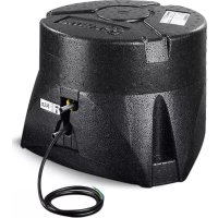
4 Control unit
5 Battery
6 Safety socket

Exemple de montage
Symbols used 16
Safety instructions 16
General instructions 17
Batteries 17
Function description 17
Operating instructions
Remote control 18
Switching on the remote control 18
Remote control LED blink code and audio signal 18
Remote control battery change 19
Disposal 19
Manoeuvring the caravan 19
Coupling to a towing vehicle 19
Maintenance 19
Checks 20
Emergency disengagement 20
Troubleshooting 20
Tuning the electronic control unit to the radio remote
control 20
Technical data 21
EU Declaration of Conformity 21
Manufacturer's Warranty (European Union) 22
Installation instructions
Intended use 23
Approval 23
Tools and facilities required 23
Minimum installation dimensions 23
Measuring the frame height 23
Determining the installation type 23
Special accessory installation 24
Selecting a location 24
Mud guards 24
Fitting the drive elements 25
Electrical wiring and control unit 26
Connecting the battery 27
Connecting the safety socket 28
Function check 28
Warnings 28
Symbols used

Symbol indicates a possible hazard.

Note containing information and tips.
Safety instructions
Only competent and trained persons (experts) may install, repair and carry out the functional test on the Tru ma product in accordance with the installation and operating instructions and the currently accepted technical regulations. Experts are persons who, based on their specialist instruction and training, their knowledge and experience with Truma products and the relevant standards, can carry out the necessary work properly and identify potential hazards.
-
This appliance may be used by children from 8 years old and by persons with disabilities or with a lack of experience only if they are supervised or have been instructed in the safe use of the appliance and understand the resulting risks. Children must not be allowed to play with the appliance.
-
Before using the Mover XT / XT2 outdoors for the first time, practice with it to familiarise yourself with the functions of the remote control and the Mover XT / XT2.
- Before using the Mover XT4 outdoors for the first time, practice with it to familiarise yourself with the functions of the remote control and the Mover XT4.
- Before each use of the Mover XT4, check tyres and drive rollers, removing any sharp stones and similar objects.
- The side slide switch on the remote control (ON/OFF) also serves as an "Emergency Stop switch". Switch the side slide switch to "OFF" immediately in the event of any abnormalities, e. g. uncontrolled behaviour of the manoeuvring system.
-
No person must be present in the caravan during operation.
-
There must be no persons (particularly children) inside the turning and movement range (manoeuvring range) of the mobile home.
- When engaging and disengaging and while operating the Mover XT4, care must be taken to ensure that no hair, parts of the body, clothing or other parts on the body can become caught in moving and / or rotating parts (such as drive rollers).
- During manoeuvring, the distance between the radio remote control and the middle of the caravan must not exceed 10m .
- In the event of a malfunction, apply the parking brake.
- In order to avoid tilting the caravan, when manoeuvring on slopes the drawbar should be pointed downwards (downhill).
- After manoeuvring, always apply the parking brake first, disengage the drive rollers from the tyres and block the wheels (especially on sloping surfaces!). The Mover XT4 is not suitable for use as a parking brake for a parked caravan.
- Always protect the radio remote control from unauthorised access (paying particular attention to children).
- Never tow the caravan with the drive rollers engaged, as this may cause damage to the tyres, the towing vehicle and the drive assemblies.
-
All wheels and tyres on the caravan must be of the same size and type.
In order to ensure that the Mover XT4 operates correctly, the gap between the tyres and the disengaged drive rollers must be 20mm . All tyres must be inflated to the same pressure in accordance with manufacturer's instructions and checked regularly. Tyre wear or the fitting of new tyres may make it necessary to readjust the gap between the drive rollers and the tyres (see "Fitting the drive elements"). -
When using a jack, the Mover XT4 must not be used as a jacking point, as this may damage the drive assembly.
- Sensitive objects such as cameras, DVD players etc. must not be kept in the stowage box near the control unit or the motor cables, as the powerful electromagnetic fields may damage them.
- The empty weight of the vehicle is increased by the weight of the Mover XT4, thus reducing the vehicle's payload.
- Remove the plug / adapter from the safety socket after manoeuvring, otherwise the battery will be discharged. Quiescent current with plug / adapter inserted < 80mA . Quiescent current with plug / adapter unplugged < 150 .
- Inspect the system for damage before use. The system must not be used if it is damaged.
General instructions
The Mover XT4 has been designed to cope with inclines of up to approx. 10% bearing a gross weight of 3100kg on a suitable surface.
Depending on the weight of the caravan, the Mover XT4 may not be able to overcome obstacles more than about 5 cm in height without auxiliary equipment (please use ascent chocks).
As a result of the characteristic properties of a radio signal, it may be interrupted by terrain / objects. This reduces reception quality in small areas around the caravan, as a result of which the operation of the Mover XT4 may be briefly interrupted.
When the Mover XT4 is switched off using the remote control, the control unit remains in standby for one hour. In order to switch off completely the battery must be disconnected or an isolating switch installed.
Batteries
Recommended battery capacities
| Button cell technology at least 55 Ah | |
| Gel / AGM at least 70 Ah | |
| Lead-acid battery (liquid electrolyte) at least 80 Ah | |
| Starter batteries are not suitable | |

Batteries with greater capacity allow the equipment to be used for longer.
Charger
For optimum battery charging we recommend the Truma BC 10 charger, which is suitable for all battery types up to 200 Ah.
Notes for handling batteries
- When handling batteries, pay attention to the manufacturer's safety instructions and data sheets
- Ensure that the terminal clamps are secure.
- Secure battery poles with protection caps in order to prevent a short circuit
- When removing the battery, first disconnect the earth connection (negative terminal), followed by the positive terminal. When installing the battery, first connect the positive terminal followed by the negative terminal.
Battery care (including maintenance-free batteries)
In order to achieve a long battery service life, attention must be paid to the following points:
- Batteries should be fully charged before and after removing power,
for stationary periods of longer than 24 hours, interrupt power circuit (e.g. using circuit breaker or by disconnecting the battery poles),
for longer stop periods the battery must be disconnected and charged for 24 hours at least every 12 weeks.

In winter, store fully charged battery in a cool and frost-free place and recharge at regular intervals (every 12 weeks).
Function description
Always observe the operating instructions and the "Safety instructions" prior to starting! The vehicle owner is responsible for correct operation of the device.
Please note that the Mover XT4 is only suitable for twin-axle trailers.
The Mover XT4 is a manoeuvring system which allows a caravan to be manoeuvred without the aid of the towing vehicle.
It consists of four separate drive assemblies, each with its own 12 V DC motor. These units are mounted on the frame of the vehicle in the immediate vicinity of the wheels, and are connected by a lateral bar.
Once the drive rollers have been engaged using the remote control, the Mover XT4 is ready for operation. It is operated exclusively via the remote control, which transmits radio signals to the control unit. A separately installed 12V lead-acid battery or suitable lead-gel battery (not supplied) provides the control unit with electrical power.
Remote control

Protect the remote control from moisture and direct sunlight.
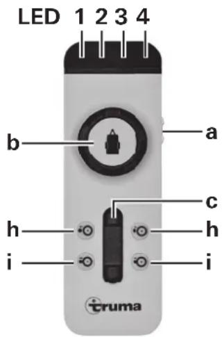
Figure 2
Switching on the remote control
a = On / Off slide switch

No other remote control function must be active when the remote control is switched on.
On (LED 4 lights up)
- Off (LED 4 goes off)
LED 4 flashes for approx. 5 seconds after the remote control is switched on, until the system is ready for operation.
The following options are available for controlling the caravan:
b using the control knob only
c using the slide control only
b + c using the control knob and the slide control
The caravan symbol on the control knob indicates the current direction of travel (of the caravan).
The slide control allows the caravan to be moved forwards and backwards without jerking, with infinitely variable speed control.
Slide control only
(Forwards, backwards and infinitely variable speed control)
-
Push slide control forwards -> caravan moves forwards (in the direction of the drawbar) (both wheels rotate forwards)
-
Pull slide control backwards-> caravan moves backwards (in the opposite direction to the drawbar) (both wheels rotate backwards)
The further the slide control is moved from the zero position, the faster the speed.
Control knob Mover XT4
The caravan drawbar can be rotated to the right / left within a range of approx. 30cm using the control knob. When the limit of the rotating range is reached, the rotating procedure is stopped automatically.
To continue rotating, the caravan must be moved forwards or backwards in a straight line for a certain distance using the slide control.
Control knob and slide control Mover XT4
(Caravan right or left and forwards or backwards)
Operating the control knob and the slide control makes the Mover XT4 go round in a circle, whereby the wheels rotate continuously but the inner wheels rotate more slowly than the outer wheels.
- Turn control knob to right and push slide control forwards -> caravan drawbar moves to right left wheel rotates fast - right wheel rotates slowly forwards
- Turn control knob to left and push slide control forwards -> caravan drawbar moves to left left wheel rotates slowly - right wheel rotates fast forwards
- Turn control knob to right and pull slide control backwards -> caravan drawbar moves to right left wheel rotates slowly - right wheel rotates fast backwards
- Turn control knob to left and pull slide control backwards -> caravan drawbar moves to left left wheel rotates fast - right wheel rotates slowly backwards
The further the slide control is pushed forwards the end stop, the faster the speed (freely selectable turning radius and speed).
Engaging and disengaging
h = Two-handed operation disengagement of drive rollers (drive rollers swing away from tyres)
i = Two-handed operation engagement of drive rollers (drive rollers swing towards tyres)
In order to engage and disengage the drive rollers, both buttons must always be pressed simultaneously - for approx. 3 seconds (safety delay) - until the engaging or disengaging of the drive rollers commences.
The buttons can be released when the drive rollers are moving in the direction of the respective end position. The drive rollers automatically reach their end position.

If the two buttons for disengaging are pressed whilst the rollers are engaging, engaging is interrupted, the drive rollre disengaged and automatically move to their end position
The remote control switches itself off after about 1 minute if none of the buttons are pressed. The green LED 4 goes out.
To reactivate the remote control, move slide switch to "Off" and then back to "On" after approximately 1 second.
There is no "On / Off" switch on the caravan itself.
Remote control LED blink code and audio signal
LED 1 red indicates state of charge of caravan battery good LED off weak LED on empty LED on and LED 3 indicates a fault
LED 2 yellow lights up in the event of a temporary malfunction, and an acoustic signal is also emitted
in the event of overcurrent / overtemperature The power is automatically reduced. Allow system to cool.
flashes if the Mover is engaged and the control unit or the remote control has been switched off.
LED 3 red
lights up in the event of a persistent fault, and an acoustic signal is also emitted e.g. in the event of a faulty drive motor apply the parking brake. See "Troubleshooting"
LED 4 green flashes if radio connection has not yet been established after switching on the remote control
lights up when remote control is ready for operation and the data link is stable
flashes in combination with acoustic signal
- 10 seconds after switching on the remote control if the control unit is not yet ready for operation
- if the control unit has been switched off
- after 1 minute without pressing a button on the remote control
- after a radio communication interruption
All LEDs "off" and no audio signal
System off (check batteries in remote control if necessary)
Remote control battery change
Please only use leak-proof micro-batteries with a steel outer casing, type LR 03, AAA, AM 4, MN 2400 (1.5 V).
When inserting new batteries, take care not to reverse the positive and negative terminals.
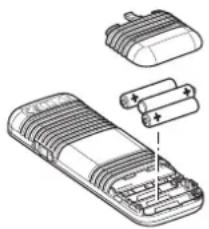
Figure 3
Empty, used batteries can leak and damage the remote control! Remove the batteries if the remote control is not being used for a long period of time.
No warranty is given for damage caused by leaking batteries.
Disposal
Neither the remote control nor the batteries may be disposed of with domestic refuse, instead they must be sent for recycling separately via a collection point. By doing this you are contributing towards reuse and recycling.
Manoeuvring the caravan
Follow the "Safety instructions" before using the Mover XT4.
Apply parking brake if caravan is uncoupled.
Disconnect 13-pin plug / adapter from vehicle and plug into safety socket of caravan.
For safety reasons, the Mover XT4 can only be operated if the 13-pin plug / adapter of the caravan is plugged into the safety socket.
In the event of a malfunction, the 13-pin plug / adapter must not be removed from the safety socket until the parking brake has been applied, since removing the plug disables the electronic safety functions.
Switch on the remote control - green LED 4 flashes until the control unit is ready for operation. If the control unit is not ready for operation, the remote control switches off after about 10 seconds. Press the two buttons (i) for engaging simultaneously, and engaging will start after approx. 3 seconds (safety delay).
Use the position indicator to check that all drive rollers are correctly engaged.
Before starting the Mover XT4, release the parking brake. The caravan can be moved in all directions using the control knob and the slide control.
With the Mover XT4 rotation around the vertical axis by about 30~cm per side (measured at the drawbar) can be carried out with the end stop at the control knob (left and right stop)
The Softstart / Softstop makes the caravan start to move without jolting, and brakes it gently when stopping.
When the control knob or slide control are released, or if the radio signal is interrupted or becomes too weak, the caravan stops moving. Radio equipment and other Mover remote controls will not activate your Mover.
After start-up, the Mover XT4 moves at a steady speed (according to the setting on the slide control). Speed increases slightly on downhill slopes and decreases on uphill slopes.
After manoeuvring, apply the parking brake first and then disengage the drive rollers from the tyres.
Move slide switch on remote control to the "Off" position to switch the remote control off (the Mover XT4 switches to standby mode).
The slide switch also acts as an "Emergency Stop" switch.
Remove the plug / adapter from the safety socket after manoeuvring, otherwise the control unit will automatically switch off after 1 hour. When the plug / adapter is inserted, the battery is discharged with a quiescent current of approx. 80mA (with approx. 150~ A after one hour).
Coupling to a towing vehicle
The Mover XT4 allows a caravan to be coupled to a towing vehicle without jolting and with millimetric precision. However, this requires care and a degree of practice.
Following the operating instructions, move the caravan close to the towing vehicle (apply parking brake and engage gear). In order to position the caravan precisely, operate the control knob or slide control until the caravan's coupling is located precisely over the ball coupling on the towing vehicle. Then couple the caravan to the vehicle by lowering it at the support wheel in the usual manner.
Prepare the caravan for towing in the usual way. The caravan must not be towed with the drive rollers engaged.
Maintenance
Keep drive elements clear of coarse road dirt. When cleaning the caravan, spray the Mover XT4 with a water hose to remove mud etc. Make sure that no stones, twigs etc. are trapped in it. The control unit does not require servicing. The remote control must be kept in a dry place.
Clean the Mover XT4 as described above every year (or before overwintering). Do not park the caravan with the drive rollers engaged.
To prevent the battery from becoming totally discharged during long periods of inactivity it must be disconnected and recharged before using again. Charge the caravan battery before starting up.
It is extremely easy for you or your caravan dealer to perform the checking and maintenance of your Mover XT4 during the annual inspection of your caravan. If in doubt, please contact Truma Service or one of our authorised service partners (see www.truma.com).
Checks
- Check the installation, wiring and connections for damage at regular intervals. The drive assemblies must be able to move freely and be returned automatically to the safe idle position when they are disengaged. If this is not the case, check the drive assemblies for dirt or corrosion on their guides and clean them if necessary to ensure they can move properly.
- After a prolonged period of non-use (e.g. overwintering), check that all motors respond correctly to commands from the remote control.
- At least every 2 years, an expert must check the Mover XT4 for rust, check that detachable parts are firmly attached and check that all safety-related parts are in good working order.
Emergency disengagement
If the caravan battery is discharged to the extent that electrical disengagement no longer works, or if a defect is present, disengagement can also be performed manually.
Prise out the plastic cap (m) at the rear end of the cover using a screwdriver. Attach the socket wrench (WAF 7 - included in scope of delivery) to the hex bolt and disengage drive assembly by rotating clockwise. Repeat procedure for all drive assemblies
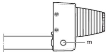
Figure 4
Once the battery has been charged or the fault remedied, the rollers can be engaged electrically again.
Troubleshooting
Check that the batteries in the remote control are in immaculate condition!
Check whether the caravan plug / adapter has been plugged into the safety socket!
Check whether the caravan battery is in immaculate condition and is fully charged! Please note that battery performance can deteriorate considerably at cold ambient temperatures.
Check that the fuse in the battery connector cable is in order. If the fuse is defective, check the connector cable for possible short circuits.
In the event of a system error (remote control LED 3 lights up red), apply the parking brake, switch off the remote control and switch it back on again after 2 seconds!
Perform a reset with the parking brake applied, which takes approx. 10 seconds (briefly disconnect battery or disconnect and reconnect safety plug)!
If these actions do not remedy the problem, please contact TrumaService.
Tuning the electronic control unit to the radio remote control

The remote control and the control unit are tuned to each other in the factory.
If the control unit or the remote control is replaced, they must be tuned to each other again in accordance with the instructions below.
Check that installation has been carried out in accordance with the installation instructions, and make sure that the drive rollers are not engaged. Check that the battery is properly connected and in good condition, and that the control unit is being supplied with 12V . Make sure that the caravan connector is plugged into the safety socket.

Please read all the following instructions beforehand, as you only have a limited time for tuning (approx. 10 seconds).

You will need a pen, a small screwdriver or similar to press the reset button (k).
- Switch off the remote control.
-
Switch on the control unit and wait for about 15 seconds until the red LED (j) starts flashing slowly.
-
Press the reset button (k) on the control unit until the red LED (j) flashes rapidly.
-
Hold the swivel in button (i) on the remote control depressed and switch on the remote control with the slide switch (a). Release the swivel in button (i).
-
When the devices are tuned, the red LED (j) on the control unit and the green LED on the remote control (LED 4) remain permanently on.

If tuning was unsuccessful, the red LED (j) flashes and you have to repeat the process.
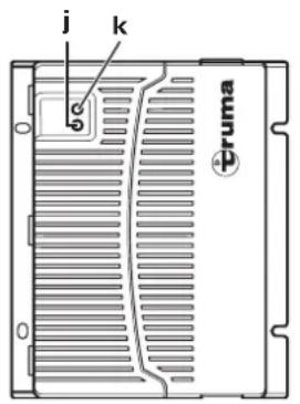
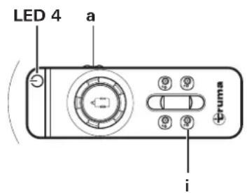
Figure 5
Technical data
Operating voltage
12VDC
Power consumption
on average approx. 37 A up to a maximum of 150 A
Quiescent current consumption
< 80 mA (with plug / adapter inserted)
< 150 A (plug / adapter disconnected or after 1 hour with plug / adapter inserted)
Radio frequency
Class 2,868 MHz
Speed
approximately 17 cm per second
Depending on weight and incline
Weight
approx. 60kg
Positive line fuse
150A
Mover XT4 range of use
Dual-axle caravans with a gross weight of up to 3100kg

Subject to technical changes.
EU Declaration of Conformity
Product
Function: Manoeuvring assistant
Type: Mover XT
Versions: Mover XT, Mover XT2, Mover XT L, Mover XT4
Mover HR XT, Mover HR XT2, Mover HR XT L, Mover HR XT4
Manufacturer
85640 Putzbrunn, Germany
This declaration of conformity is issued under the sole responsibility of the manufacturer.
The product is in conformity with the relevant Union harmonisation legislation:
Directive 2014/53/EU Radio equipment
The following (harmonised) standards and other technical specifications were used:
EN 300 220-1 V3.1.1; EN 300 220-2 V3.1.1
EN 301 489-1 V1.9.2; EN 301 489-3 V1.6.1
EN 60950-1:2006/A2:2013
The KBA, 24932 Flensburg, Germany issued the type approval(s):
E1 10R-05 6968
Signed for and on behalf of:
Manufacturer's Warranty (European Union)
1. Scope of Manufacturer's Warranty
As the Manufacturer of the unit, Truma undertakes a warranty towards the Consumer that covers any material and/or manufacturing defects of the unit.
This Warranty is applicable in EU member states as well as in Iceland, Norway, Switzerland and Turkey. A Consumer is the natural person who was the first one to purchase the unit from the Manufacturer, OEM or dealer and who neither resold the unit in a commercial or self-employed professional capacity nor did he or she install it for a third party in such a capacity.
The Manufacturer's Warranty covers any of the aforementioned defects that occur within 24 months upon concluding the purchase agreement between the seller and the Consumer. The Manufacturer or an authorised service partner undertakes to remedy such defects through subsequent fulfilment, i.e. at its discretion either by repairing or replacing the defective item. Any defective parts shall become the property of the Manufacturer or the authorised service partner. If the unit is no longer manufactured at the time of defect notification and if replacement delivery has been opted for, then the Manufacturer may deliver a similar product.
If the Manufacturer remedies a defect under its warranty commitment, the term of the Warranty shall not recommence anew with regard to the repaired or replaced parts; rather, the original warranty period shall continue to be applicable to the unit. Only the Manufacturer itself and an authorised service partner shall be entitled to conduct a warranty job. Any costs that occur in the event of a warranty claim shall be settled directly between the authorised service partner and the Manufacturer.
The Warranty does not cover additional costs arising from complicated removal or installation jobs on the unit (e.g. dismantling of furnishings or parts of the vehicle body), and neither does it cover travel expenses incurred by the authorised service partner or the Manufacturer.
No further-reaching claims shall be permitted, especially damage claims presented by the Consumer or third parties. This provision shall not affect the validity of the German Product Liability Act (Produkttaftungsgesetz).
Neither does the voluntary Manufacturer's Warranty affects the Consumer's legally applicable claims for defects towards the seller in the relevant country of purchase. In individual countries there may be warranties that can be issued by the relevant dealer (official distributor, Truma Partner). In such cases the warranty can be implemented directly through the dealer from whom the Consumer bought the unit. The warranty regulations of the country in which the unit was purchased by the Consumer for the first time shall also be applicable.
2. Warranty exclusions
No warranty claim shall be applicable under the following circumstances:
- Improper, unsuitable, faulty or negligent use and any use that is not compliant with the intended purpose
- Improper installation, assembly or commissioning, contrary to operating or installation instructions
- Improper operation or operation contrary to operating or installation instructions, particularly any disregard for maintenance, care or warning notes,
- Instances where installations, repairs or any other procedures have been conducted by non-authorised parties
-
Consumable materials and parts which are subject to natural wear and tear
-
Installation of replacement, supplementary or accessory parts that are not original manufacturer's parts or which have not been approved by the manufacturer. If the device is subject to networked control, this applies, in particular, if the control units or the software have not been approved by Truma or if the Truma control unit (e.g. Truma CP plus or Truma iNet Box) has not been exclusively used for controlling Truma devices or devices approved by Truma.
- Damage arising from foreign substances (e.g. oil or, plasticisers in the gas), chemical or electrochemical influences in the water, or cases when the unit has come into contact with unsuitable substances (e.g. chemical products, flammable substances or unsuitable cleaning agents)
- Damage caused by abnormal environmental or unsuitable operating conditions
- Damage caused by force majeure or natural disasters or any other influences not within Truma's responsibility
- Damage resulting from improper transport
- End customer's or third-party modifications of the device, including any replacement, supplementary or accessory parts, or installation of the same, especially concerning the exhaust gas system or the cowl.
3. Making a warranty claim
The warranty must be claimed with an authorised service partner or at the Truma Service Centre. All the relevant addresses and phone numbers can be found at www.truma.com, in the "Service" section.
The Manufacturer's address is:
85640 Putzbrunn, Germany
To ensure a smooth procedure, we should be grateful if you could have the following details ready before contacting us:
Detailed description of the defect
- Serial number of the unit
-Date of purchase
The authorised service partner or the Truma Service Centre will then specify the further procedure. To avoid transport damage, the affected unit must only be shipped upon prior arrangement with the authorised service partner or the Truma Service Centre.
If the warranty claim is recognised by the Manufacturer, then the transport expenses shall be borne by the same. If no warranty claim is applicable, the Consumer will be notified accordingly and any repair and transport expenses shall then be the Consumer's liability. We must ask you not to send in a unit without prior arrangement.
Installation instructions
Only competent and trained persons (experts) may install, repair and carry out the functional test on the Truma product in accordance with the installation and operating instructions and the currently accepted technical regulations. Experts are persons who, based on their specialist instruction and training, their knowledge and experience with Truma products and the relevant standards, can carry out the necessary work properly and identify potential hazards.
Please ensure that no metal chips or other contaminants get into the control unit during installation.
In the case of screws with sealant, make sure that the thread is free of grease / oil.
Intended use
The Mover XT4 has been designed for use on twin-axle caravans with a gross weight of up to 3100kg
The Mover XT4 weighs approx. 60kg
Check the maximum towable weight for your towing vehicle and the gross weight of your caravan to make sure that they are designed for this additional weight.
Approval
The Truma Mover XT4 has design approval, and a "general operating permit" (ABE) has been issued for Germany. Acceptance by a vehicle expert is not required (except when installing the low chassis kit). The general operating permit (ABE) must be kept in the vehicle.
The Mover XT4 complies with other requirements of EC Directives and Standards (see Declaration of conformity).
When installing the Mover XT4, the technical and administrative regulations of the country of first registration of the vehicle must be observed.
Any modifications made to the device, or the use of any spare parts or functionally significant accessories other than original Truma parts, or failure to comply with the contents of the operating and installation instructions invalidates the warranty and precludes any liability claims. This will also invalidate the operating permit for the equipment.
Tools and facilities required
To install the Mover XT4 you need:
- 8 mm, 10 mm, 13 mm and 17 mm socket wrenches, ring spanners or open-jawed spanners
-Allenkey4 - Torque wrenches (3.5 - 50 Nm)
Cable cutter / crimping tool - Electric drill / screwdriver / keyhole saw, diameter 25 mm
- 2-tonne trolley jack and suitable support trestles
- Adequate lighting
Minimum installation dimensions
A distinction is made between L-profile and U-profile frames as shown in the illustration.
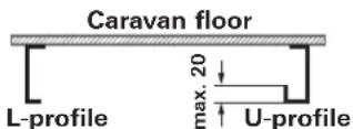
Figure 6
Installation is only possible on caravans with the following dimensions.
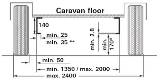
Figure 7
All dimensions in mm.
- with loaded vehicle with max. permissible gross weight
** with U-profile
Measuring the frame height
A frame height of at least 140mm is required at the level of the tyre hub / tyre centre in the range of 320mm from the outer edge of the tyre.
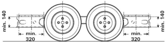
Figure 8
Determining the installation type
1. Standard installation
Standard installation is used with a U-profile or L-profile chassis and a frame height of at least 140mm . No special accessories are required.
- Installation on chassis with U-profile or L-profile and a frame height of between 80mm and less than 140mm In order to compensate for height, the 30~mm spacer set (for frame heights down to 110mm ) or the 60~mm spacer set (for frame heights of less than 110mm down to 80mm ) is required.
3. Installation on chassis with U-profiles or L-profiles with a frame height of less than 80mm
If the chassis has a frame height of less than 80mm a low chassis kit must be fitted to compensate for the height.
If a low chassis kit is used in Germany, acceptance by a vehicle expert is required.
4. Installation on chassis with L-profile and with a limited amount of space
The short mounting system is required to compensate for the height (30 or 60~mm ) with substructures such as tanks.
Special accessory installation
1. Spacer kit 30 mm
To compensate for the height for caravans with a frame height of < 140mm to 110mm , part no. 60030-95000.
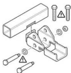
Figure 9
2. Spacer kit 60 mm
To compensate for the height for caravans with a frame height of < 110mm to 80mm , part no. 60030-95100.
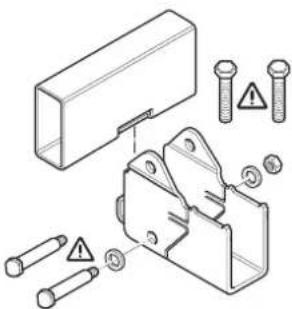
Figure 10
3. Low chassis kit
For compensating for height on caravans with a frame height of less than 80mm and /or for bridging struts, part no. 60010-64900.
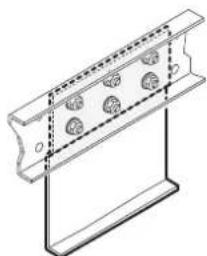

Figure 11
If a low chassis kit is used in Germany, acceptance by a vehicle expert is required.
4. Low chassis kit, short
For compensating for height on caravans with a frame height of less than 80 mm, part no. 60030-37600.
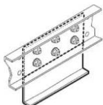

Figure 12
If a low chassis kit is used in Germany, acceptance by a vehicle expert is required.
5. Short mounting system
Replacement for standard mounting system if this cannot be used due to lack of space and to compensate for the height (30 or 60 mm) of substructures such as tanks. Part no. 60031-20000.
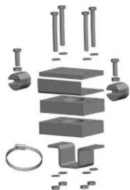
Figure 13
6. Mud guard set (no illustration)
Replacement for the standard mud guards, if these cannot be adapted to the Mover.
Part. no. 60031-08200

In some cases installation is not possible because of the design of the sub-frame. Contact your dealer if sary.

Detailed installation instructions are included with each mounting set.

The Mover XT4 must not be fitted to caravans with other frames.
The vehicle frame must not be drilled or welded. Wheel suspension parts must not be removed under any circumstances.
Selecting a location
Only use the bolts provided (or the mounting parts available as special accessories) to attach the Mover XT4.
Mud guards
When a Mover is fitted, the existing mud guards must be moved / adapted if necessary (max. distance between tyre / mud guard 300 mm).
If the original mud guards cannot be used, the Truma mud guard set (part no. 60031-08200) must be used and adapted.

The mud guards are installed behind the axle. No mud guards are required in front of the axle.
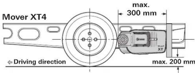
Figure 14
Adapting the mud guards to the Mover
- Remove the mud guards.
- Fit Mover in accordance with the following installation instructions.
- Determine dimensions a and b and transfer to mud guards. The top leg of the fastening bracket must face towards the rear of the caravan.
Determining the cut-out sizes
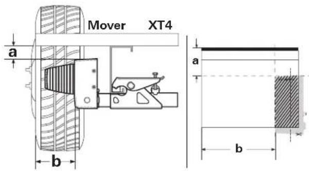
Figure 15
Cut out the template at the end of the installation instructions, place onto mud guard, transfer contour and cut out (figure 6).

Pay attention to left and right sides!
If necessary, make recesses in the mud guard for the apron contour. Secure the mud guard 300mm from the tyre on the underside of the caravan.
Fitting the drive elements
The frame of the vehicle must be free of rust, grease and heavy soiling. There must be no damage in the area of the wheel suspension.
The wheels and tyres fitted on the caravan must be of the same size and type, and must be inflated in accordance with manufacturer's instructions.
Remove all components from packing and place on the floor.
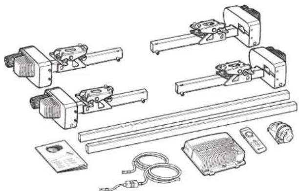
Figure 16
In order to guarantee the validity of the general operating permit (ABE), the type plates(f) must be present on the cross-struts (4 x).
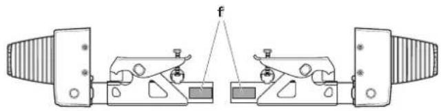
Figure 17
Mark the connection pipes in the centre. Loosely connect the drive assemblies with connection pipes.

Do not screw in the supplied threaded bolts (g) yet.
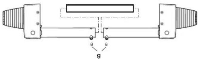
Figure 18
Place the drive assemblies with the connection pipe and mounting kit (b) on the vehicle frame and bolt them on with the two bolts (c) in such a way that it is just possible to move them along the frame.

The gripper (a) must be lying flat against the chassis frame (e) in its entirety and also flat against the leg (d).
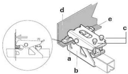
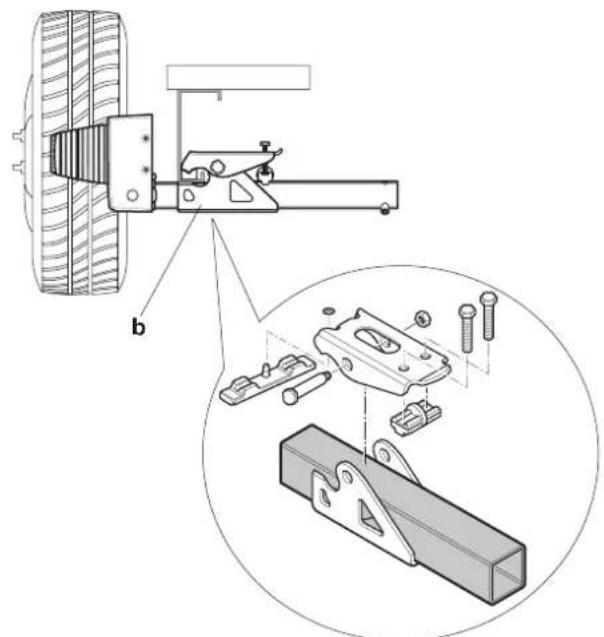
Figure 19
Figure 20
If the frame is not high enough, Truma can provide 30 mm and 60 mm spacer sets as accessories in order to compensate for this.
Spacer kit 30~mm part no.60030-95000,
Spacer kit 60 mm, part no. 60030-95100
Make sure that there is adequate ground clearance (at least 110mm ).
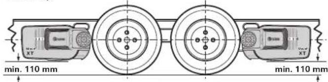
Figure 21
Set the correct distance between tyres and rollers (20mm) with the spacer gauge provided by moving the drive assemblies (in the disengaged position) in the longitudinal direction. The movable connection pipe makes it possible to adjust to the frame width.
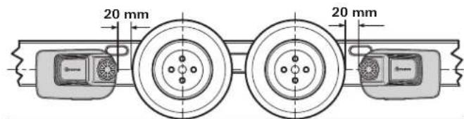
Figure 22
Move the drive assemblies in a lateral direction in such a way that as much of the tread area of the tyre / drive roller as possible is covered.
Once the drive assemblies have been correctly positioned, tighten the bolts (c) of the mounting set a little, then check the required distances again. The weight of the caravan must be resting on the wheels when doing this.
Place the movable connection pipes in the centre (use the marking) and fix each one with a threaded bolt (g) M8 x 12 (15 Nm).

The threaded bolts are coated with sealant, and must therefore only be bolted in once.
Re-check the distance of 20mm from the tyre (with the wheels under load). Then tighten the 2 bolts of the mounting set (M10) alternately to 25Nm .
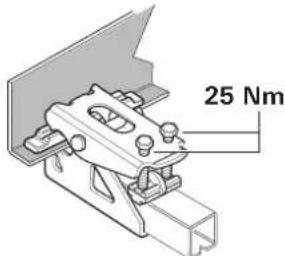

Figure 23
The bolts are coated with sealant, and must therefore only be bolted in once.
Position indicator
Indicates how far the Mover XT4 is engaged. No figure visible: Disengaged position Figures 1 to 3 visible: Engaged position
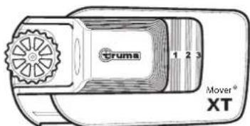
Figure 24
Electrical wiring and control unit
The Mover XT4 is only suitable for connection to 12V batteries (DC voltage).

Before commencing work, disconnect the battery and any external electrical power supplies. If unsure about electrical connection, have the work performed by a quali-vehicle electrician.
The electrical installation must comply with the technical and administrative regulations of the respective country of use (e.g. EN 1648-1). National regulations and rules must be followed.
Connector cables for the drive motor and data cables are preinstalled on each drive assembly. Mark the relevant motor connecting cables (drive assembly A or B - see also connecting diagram) and temporarily route them along the underbody of the caravan to the location where it is planned to install the control unit. An example of a suitable location for the control unit is in a bed stowage box in close proximity to the manoeuvring system, at least 40~cm away from the battery.
Place the control unit in the stowage box and secure with the chipboard screws provided (5× 25)
At a distance of approx. 150mm from the control unit connection strip, mark a hole with a diameter of 25mm on the floor of the caravan through which to pass the wiring looms.

Before drilling, check for underlying frame sections, gas lines and electrical cables.
Drill the hole and pass the cables through the floor of the caravan to the control unit, routing them in such a way that they cannot chafe (especially where they pass through metal panels). Use the protection pipes provided to prevent damage to cables.

The drive motors move when operating. In order to
compensate for this, secure the cables in this area loosely with a little play to prevent the cables from being stretched. No cable must be laid over the control unit.
Secure the cables to the chassis or underbody using the clips and screws provided.
Seal the hole in the vehicle floor with plastic body sealant.
Connecting diagram
Assembly in front of and behind the axle (Top view)
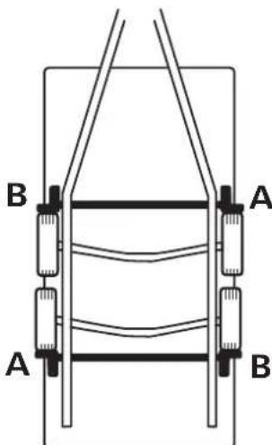
Figure 25
| PIN Description | (Figure 26) |
| Battery (C) | |
| Battery + Battery + terminal, red 25 mm² | |
| Battery - Battery - terminal, black 25 mm² | |
| Drive assemblies in front of the axle | |
| Motor left + (B) Motor left + terminal, red 10 mm² | |
| Motor left - (B) Motor left - terminal, black 10 mm² | |
| Motor right + (A) Motor right + terminal, red 10 mm² | |
| Motor right - (A) Motor right - terminal, black 10 mm² | |
| Drive assemblies behind the axle | |
| Motor left + (A) Motor left + terminal, red 10 mm² | |
| Motor left - (A) Motor left - terminal, black 10 mm² | |
| Motor right + (B) Motor right + terminal, red 10 mm² | |
| Motor right - (B) Motor right - terminal, black 10 mm² | |
| Connector block (D) | |
| K1-1 Safety socket, black | |
| K1-2 Safety socket, black / red | |
| K1-3 Data cable motor left, black 0.5 mm² | |
| K1-4 Data cable motor left, black / red 0.5 mm² | |
| K1-5 Data cable motor right, black 0.5 mm² | |
| K1-6 Data cable motor right, black / red 0.5 mm² | |
| K1-7 Data cable motor left, black 0.5 mm² | |
| K1-8 Data cable motor left, black / red 0.5 mm² | |
| K1-9 Data cable motor right, black 0.5 mm² | |
| K1-10 Data cable motor right, black / red 0.5 mm² | |
| Diagnostic interface (E) | |
| J 1 Diagnostic interface | |

If the data cables are incorrectly assigned, the system cannot be initialised
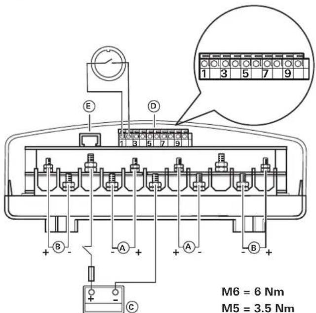
Figure 26
Once the cables have been routed out of the control unit, they must be strain-relieved.
Connecting the drive motors
The data and motor cables must be routed together in such a way that they cannot be torn off or damaged.

The cables may be shortened. Please pay attention to different ring eyelet sizes.
Release the cover of the control unit by applying lateral pressure to the latching lugs, and clamp the cables as shown in the connecting diagram (red = positive, black = negative). Please ensure that the connections are made properly. (Torque M5 = 3.5 Nm / M6 = 6.0 Nm)
Connecting the battery
Liquid electrolyte batteries must be installed in a separate box with ventilation leading to the outside. The fuse in the positive lead must be connected outside the box. A separate box is not required for gel or AGM batteries. Pay attention to the battery manufacturer's installation instructions.
The outgoing lines from the terminals must be routed with a gap between them until after the fuse in the positive lead.
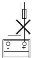
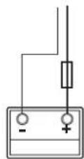
Figure 27
Route the battery connector cables (only use the original Truma cables supplied) to the control unit and attach them securely using the clips and screws provided.
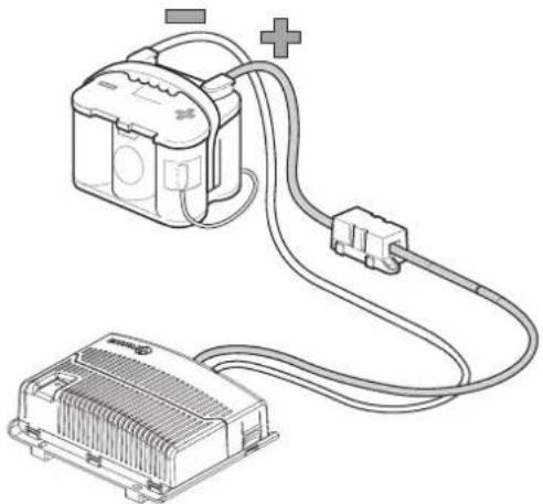
Figure 28

The battery connector cables must not be extended. They must be routed separately from the motor cables, must not run over the control unit.
Route battery connector cables so that they do not chafe (particularly at leadthroughs through metal panels). Use suitable protective leadthrough bushing to prevent damage to cables. Connect battery connector cables to the existing battery terminals (red = positive, black = negative).

Incorrect polarity will destroy the electronics / control unit
The connection to the control unit (as per the connecting diagram) must be made in the order: nut, battery connection ring eyelet, nut (torque M6 = 6.0 Nm).
Connect fuse in the positive lead (150 A) near the positive terminal.
Connecting the safety socket
Lead the supplied 2-wire cable (10m) with the flat connectors through the socket holder (g) and the rubber sleeve (h).
If necessary, open cover and push socket connection out of socket housing (i).
Connect 2-wire cable with flat connectors to micro switch.
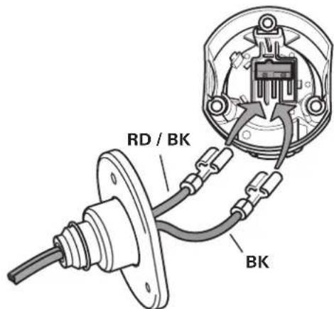
Figure 29
If necessary, insert socket connector back into socket housing (i).
Screw socket housing (i) with rubber seal (h) to socket holder (g) using 3 sheet metal screws (j). (Several positions are possible by selecting the mounting holes on the socket holder and rotating the rubber seal)
Lead cable loosely through the strain relief (k) and screw in place with the 2 sheet metal screws. Depending on the installation situation, the cable can be led out of the socket holder through one of the three recesses.
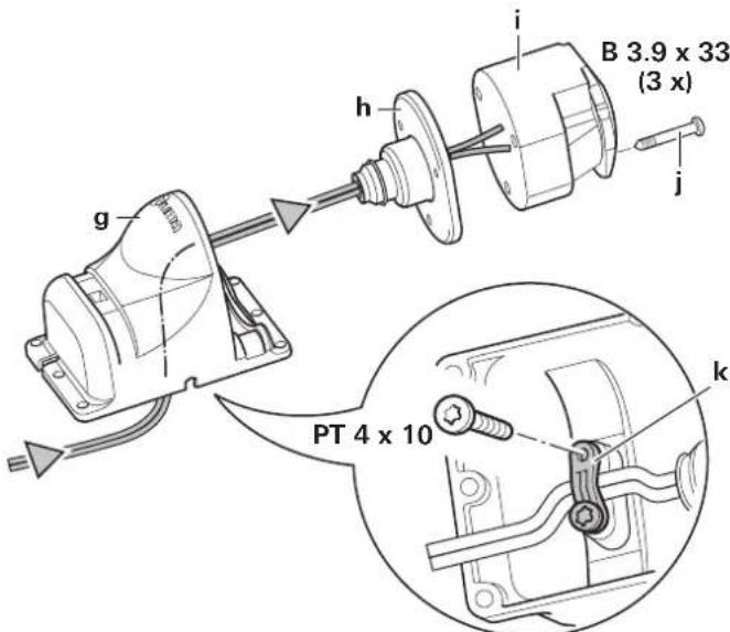
Figure 30
Secure safety socket to the (plastic) shaft cover of the caravan with 4 screws, nuts and washers.
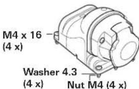
Figure 31

No holes must be drilled in the chassis.
Alternatively, the safety socket can be secured using the two hose clamps.
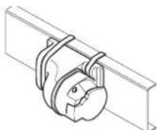
Figure 32
Route both wires to the control unit (shortening them if necessary) and connect them to the connector block as shown in the connecting diagram.
Re-check whether all cables are correctly connected, attached using the provided clips and cannot chafe.
Function check
Check whether the battery is fully charged for operating the Mover XT4.
Position the caravan on open, level ground and apply the parking brake. The drive rollers must not be in contact with the wheels and the corner jacks must be raised.
Connect the battery terminals to the battery. Check that all cables are securely attached and not hot, and that there are no signs of short circuits etc.
Plug the 13-pin plug / adapter into the safety socket.
Move slide switch on remote control to the "On" position. This switches on the remote control, and green LED 4 flashes until the control unit is ready for operation. If LED 4 does not light up, check polarity and condition of batteries in remote control.
Check whether the drive motors are stationary. With the remote control switched on, operate the "slide control (C)" and the drive motors must rotate.
Engage drive rollers using remote control.
Ensure that there are no obstacles around the caravan and release the parking brake. Now check all functions several times in accordance with the operating instructions.
Apply caravan parking brake. Disengage drive rollers and move remote control slide switch to "Off" in order to switch off the remote control and the Mover XT4. Re-check distance between drive rollers and tyres. Re-adjust if necessary.

The distance between the disengaged drive rollers and tyres is 20mm
Warnings
The installer or vehicle owner must apply the yellow sticker with the warning information, which is enclosed with the appliance, in a location in the vehicle where it is clearly visible to all users (e.g. the wardrobe door). Missing stickers can be requested from Truma.
Table des matieres
Plaquage et repliage
Sous reserve de modifications techniques!
6. Kit de bavettes anti-projections (sans illustration)
Bavettes anti-projections
a = Interrupttortarescorrimento on/off
in media circa 37 A max.150 A
Vridreglage Mover XT4
Shown left side in the direction of travel
EN Should problems occur, please contact the Truma Service Centre or one of our authorised service partners (see www.truma. com).
In order to avoid delays, please have the unit model and serial number ready (see type plate).