DMM53 - Multimeter MULTIMETRIX - Free user manual and instructions
Find the device manual for free DMM53 MULTIMETRIX in PDF.
User questions about DMM53 MULTIMETRIX
0 question about this device. Answer the ones you know or ask your own.
Ask a new question about this device
Download the instructions for your Multimeter in PDF format for free! Find your manual DMM53 - MULTIMETRIX and take your electronic device back in hand. On this page are published all the documents necessary for the use of your device. DMM53 by MULTIMETRIX.
USER MANUAL DMM53 MULTIMETRIX
Thank you for purchasing this DMM53 digital multimeter.
For best results from your instrument:
■ read these operating instructions carefully,
■ comply with the precautions for use.

WARNING, risk of DANGER! The operator must refer to these instructions whenever this danger symbol appears.

WARNING, risk of electric shock. The voltage applied to parts marked with this symbol may be hazardous.

Equipment protected by double insulation. Battery.

Information or useful tip. Fuse. Earth.


The product is declared recyclable following an analysis of the life cycle in accordance with standard ISO 14040.

Chauvin Arnoux has adopted an Eco-Design approach in order to design this appliance. Analysis of the complete lifecycle has enabled us to control and optimize the effects of the product on the environment. In particular this appliance exceeds regulation requirements with respect to recycling and reuse.


The CE marking indicates conformity with European directives, in particular LVD and EMC.

The rubbish bin with a line through it indicates that, in the European Union, the product must undergo selective disposal in compliance with Directive WEEE 2002/96/EC. This equipment must not be treated as household waste.
Definition of measurement categories:
■ Measurement category IV corresponds to measurements taken at the source of low-voltage installations. Example: power feeders, counters and protection devices.
■ Measurement category III corresponds to measurements on building installations. Example: distribution panel, circuit-breakers, machines or fixed industrial devices
■ Measurement category II corresponds to measurements taken on circuits directly connected to low-voltage installations.
Example: power supply to electro-domestic devices and portable tools.
CONTENTS
1. PRESENTATION......15
1.1. Delivery condition 15
1.2. Inserting the batteries....15
1.3. Display unit 15
1.4. Presentation of the instrument.... 15
2. USE 17
2.1. Voltage measurement.... 17
2.2. Current measurement....17
2.3. Resistance, diode, and continuity measurements....17
2.4. Capacitance measurement....17
2.5. Frequency and duty cycle measurements....18
2.6. Temperature measurement....18
2.7. Non-contact voltage detection (NCV) 18
2.8. Auto off....18
3. CHARACTERISTICS ...... 19
3.1. Reference conditions.... 19
3.2. Electrical characteristics....19
3.3.Environmental conditions 22
3.4. Power supply 22
3.5. Characteristics of construction 22
3.6. Electrical safety 22
3.7. Electromagnetic compatibility 22
4. MAINTENANCE....23
4.1. Cleaning 23
4.2. Replacement of batteries....23
4.3. Replacing the fuses....23
5. WARRANTY 23
PRECAUTIONS FOR USE
This instrument is compliant with safety standard IEC61010-2-033 and the leads are compliant with IEC61010-031, for voltages up to 600V in measurement category III.
■ Failure to observe the safety instructions may result in electric shock, fire, explosion, and destruction of the instrument and of the installations.
■ The operator and/or the responsible authority must carefully read and clearly understand the various precautions to be taken in use. Sound knowledge and a keen awareness of electrical hazards are essential when using this instrument.
If you use this instrument other than as specified, the protection it provides may be compromised, thereby endangering you.
■ Do not use your instrument on networks of which the voltage or category exceeds those stated.
■ Observe the environmental conditions of use.
■ Do not use the instrument if it seems to be damaged, incomplete, or poorly closed.
■ Before each use, check the condition of the insulation on the leads, housing, and accessories. Any item of which the insulation is deteriorated (even partially) must be set aside for repair or scrapping.
■ Use only the leads supplied. The use of leads of a lower voltage rating or category limits the use of the combined instrument + leads to the lowest category and service voltage.
■ Do not use the instrument in an explosive or dust-laden atmosphere.
■ When handling the test probes, keep your fingers behind the physical guard.
■ Use personal protection equipment systematically.
■ All troubleshooting and metrological checks must be done by competent, accredited personnel.
1. PRESENTATION
1.1. DELIVERY CONDITION
Delivered in blister pack with:
■ two 1.5V batteries (AAA or LR3),
■ one set of two leads each terminated by a probe tip,
■ one type K thermocouple,
■ one multilingual safety data sheet,
■ one user's manual in five languages.
1.2. INSERTING THE BATTERIES
■ Lift the prop.
■ Using a small cross-headed screwdriver, unscrew the screws of the battery compartment cover.
■ Withdraw the battery compartment cover.
■ Insert the two batteries provided (AAA or LR3 1.5V alkaline batteries).
- Put the battery compartment cover back in place. Make sure that it is completely and correctly closed, then screw the screws back in.
1.3. DISPLAY UNIT
When the display unit indicates OL, it is because the quantity measured lies outside the measurement range.
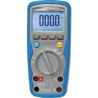
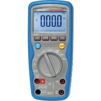
1.4. PRESENTATION OF THE INSTRUMENT
The DMM53 is an easy-to-use hand-held digital multimeter.
It can measure AC and DC voltages, AC and DC currents, resistances, capacitances, frequencies, and temperatures. It can also be used to determine duty cycles, diode voltages, and continuities and for non-contact voltage detection (NCV).
text_image
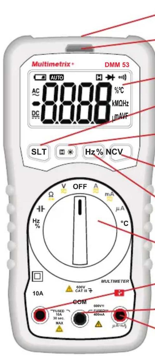
Multimetrix DMM 53 AUTO AC 0.000 0.000 %C -DC 0.000 kMΩHz μMAVF SLT H Hz% NCV OFF A mA μA °C Hz % 10A 600V CAT III MULTIMETER COM FUSED 10A 30 sec. MAX 600V= FUSED= 400mA μA·mALight with which to illuminate the measurement point.
Indicator for non-contact voltage detection.
LCD display unit.
SLT key to select AC/DC or Ω/→+/-.
H key to lock the display of the measurement and ✿ (long press) to switch on the display unit backlight and the flashlight.
NCV key for non-contact voltage detection.
Hz% key to display the frequency or the duty cycle.
Nine-position rotary switch.
10A current measurement terminal.
COM terminal.
+ terminal.
2.1. VOLTAGE MEASUREMENT
■ Connect the red lead to the + terminal and the black lead to the COM terminal.
■ Set the switch to V.
■ Place the probe tips on the element to be tested, starting with the black probe tip, and maintain firm contact.
■ The voltage is displayed.
■ At the end of the measurement, disconnect the + terminal first, then the COM terminal.
The SLT key is used to choose to display the AC voltage only or the DC voltage only. To measure a DC voltage, first check that the AC voltage is zero.
2.2. CURRENT MEASUREMENT
Before each current measurement, check the fuses.
■ Short-circuit the + and 10A terminals and make a continuity measurement. If the result is 0, the fuse in the 10A terminal is OK. If the result is OL, the fuse (F2) must be replaced.
■ Measure a known current (<400mA) between the + and COM terminals. If the result is 0, the fuse (F1) must be replaced.
To make a current measurement:
■ Cut off power to the device to be tested and discharge all high-voltage capacitors.
■ Set the switch to A, mA or A, depending on the value of the current to be measured.
■ Connect the red lead to the 10A terminal or to the + terminal and the black lead to the COM terminal.
■ Place the test probes on the element to be tested and maintain a firm contact.
■ Power up the device to be tested and read the measurement.
2.3. RESISTANCE, DIODE, AND CONTINUITY MEASUREMENTS
■ Connect the red lead to the + terminal and the black lead to the COM terminal
■ Set the switch to .
- Cut off power to the device to be tested and discharge all high-voltage capacitors.
■ Use the SLT key to select the desired function: Ω, ➤ or ⚪.
■ Place the test probes on the element to be tested and maintain a firm contact. For diode voltage measurements, place the red probe tip on the cathode and the black probe tip on the anode.
■ The measurement is displayed.

For low resistance measurements, measure the resistance of the leads by short-circuiting the probe tips. Subtract the value so found from the low resistance measurements.
2.4. CAPACITANCE MEASUREMENT
■ Connect the red lead to the + terminal and the black lead to the COM terminal
■ Set the switch to .
■ Cut off power to the device to be tested and discharge all high-voltage capacitors.
■ Place the test probes on the element to be tested and maintain a firm contact.
■ The measurement is displayed. Wait for the measurement to stabilize.
2.5. FREQUENCY AND DUTY CYCLE MEASUREMENTS
■ Connect the red lead to the + terminal and the black lead to the COM terminal
■ Set the switch to Hz.
■ Use the Hz% key to select the desired function: Hz or %.
■ Place the test probes on the element to be tested and maintain a firm contact.
■ The measurement is displayed.
2.6. TEMPERATURE MEASUREMENT
■ Connect a K thermocouple between the + and COM terminals.
■ Set the switch to °C.
■ Place the end of the thermocouple on the object or in the environment to be measured.
■ The measurement is displayed. Wait for the measurement to stabilize.
2.7. NON-CONTACT VOLTAGE DETECTION (NCV)
The instrument can detect an AC voltage greater than or equal to 110V with respect to ground.
■ Disconnect the leads.
■ Set the switch to any position except OFF.
- Keep the NCV key pressed and move the top of the instrument close to the conductor.
■ The presence of the voltage is indicated by the blinking of the indicator and by the audible signal.

The absence of a voltage indication in the NCV function does not mean that there is no voltage. To confirm the absence of a voltage, use a VAT.

The presence of other voltages nearby can trigger non-contact voltage detection.
2.8. AUTO OFF
To save the batteries, the instrument switches itself off automatically after 30 minutes if the user has not shown signs of being present by turning the switch or pressing a key.
To suppress auto off, press the SLT key while turning the switch when starting up.
3.1. REFERENCE CONDITIONS
| Quantity of influence Reference values | |
| Temperature 23 ±5°C | |
| Relative humidity <80% RH | |
| Supply voltage 3 ±0.1V | |
| Frequency of the measured signal DC or | 45 to 65Hz |
| Type of signal sinusoidal | |
| External electric field <1V/m | |
| DC external magnetic field <40A/m |
The uncertainties are expressed in % of the reading (R) and in number of display points (pt): ±(a% R + b pt)
3.2. ELECTRICAL CHARACTERISTICS
3.2.1. VOLTAGE
| DC range 400mV | 4V 40V 400V 600V | |||
| Resolution 0.1mV | 1mV | 10mV 100mV | 1V | |
| Intrinsic uncertainty | ±(0.5% R ±3 pt) | ±(0.8% R ±3 pt) | ||
| Input resistance | 10MΩ | |||
For AC measurements, the frequency is between 40 and 400Hz and the signal is sinusoidal.
| Calibre AC | 4V 40V 400V | 600V | |
| Resolution | 1mV | 10mV 100mV 1V | |
| Intrinsic uncertainty | ±(0.8% R ±5 pt) | ±(1% R±5 pt) | |
| Input resistance | 10MΩ | ||
3.2.2. RESISTANCE
| Range | 400Ω | 4kΩ | 40kΩ | 400kΩ | 4MΩ | 40MΩ |
| Resolution | 0,1Ω | 1Ω | 10Ω | 100Ω | 1kΩ | 10kΩ |
| Intrinsic uncertainty | ±(0.8% R ±5 pt) | |||||
3.2.3. DIODE AND CONTINUITY
| Function Measurement range Resolution Intrinsic uncertainty | |||
 | 3V 1mV | The display unit indicates the nearest standardized diode voltage. | |
| [ZxST] | The audible signal indicates a resistance <50Ω | Open-circuit voltage: 1V | |
3.2.4. CAPACITY
| Range 10 nF | 100 nF 1 μF | 10 μF 100 μF | 1 mF | 10 mF | |||
| Resolution | 1 pF 10 | pF 100 pF 1 | nF | 10 | nF 100 nF 1 | μF | |
| Intrinsic uncertainty | ± (3% R ±5 pt) | ||||||
3.2.5. CURRENT
| DC range | 400μA | 4000μA | 40mA | 400mA | 10A |
| Resolution | 0,1μA | 1μA | 10μA 100μA | 10mA | |
| Intrinsic uncertainty | ±(1% R ±5 pt) | ±(2% R ±10 pt) | |||
For AC measurements, the frequency is between 40 and 400Hz and the signal is sinusoidal.
| Calibre AC | 400μA | 4000μA | 40mA | 400mA | 10A |
| Resolution | 0,1μA | 1μA | 10μA | 100μA | 10mA |
| Intrinsic uncertainty | ±(1% R ±5 pt) | ±(2% R ±10 pt) | |||
For the 10A current, the measurement time must not exceed 30 seconds every 15 minutes
The 10A terminal is protected by a fuse: FF 10A H 600V 10 kA.
The + terminal is protected by a fuse: FF 400mA H 600V 10 kA.
3.2.6. FREQUENCY
In the Hz% setting
Input voltage ≥ 2V_AC . This voltage increases with the frequency to be measured.
| Range 10 Hz | 100 Hz 1 kHz | 10 kHz 100 kHz | 1 MHz | 10 MHz | |||
| Resolution 0, | 001 Hz 0,01 | Hz 0,1 Hz 1 | Hz 10 Hz 10 | Hz 100 Hz | |||
| Intrinsic uncertainty | ± (1% R ± 5 pt) | ||||||
In the A or V setting
Maximum input voltage 600 V _AC .
Input voltage ≥ 600m V _AC . This voltage increases with the frequency to be measured.
| Measurement range | 100 Hz 1000 Hz | 10 kHz 100 kHz | ||
| Resolution 0,01 Hz 0 | 1 Hz 1Hz | 10Hz | ||
| Intrinsic uncertainty | ±(1.5% R ±5 pt) | |||
3.2.7. DUTY CYCLE
| Measurement range | 0.1-99.9% |
| Resolution | 0.1% |
| Intrinsic uncertainty | ±3% |
In the Hz% setting
Frequency: 1Hz to 10 MHz.
Input voltage ≥ 2 V_AC . This voltage increases with the frequency to be measured.
In the A or V settings
Frequency: 40Hz to 100 kHz.
Input voltage ≥ 600 mV _AC . This voltage increases with the frequency to be measured.
3.2.8. TEMPERATURE
| Measurement range | -20°C ... +1000°C |
| Resolution | 1°C |
| Intrinsic uncertainty | ±(3% R ±3 pt) |
3.2.9. NON-CONTACT VOLTAGE DETECTION (NCV)
The instrument detects a line voltage ≥ 110 V _AC 50/60Hz with respect to ground.
3.3. ENVIRONMENTAL CONDITIONS
Operating range: 0 to 40°C and <80%RH without condensation up to 10°C.
Storage range (without batteries): -10 to +60°C and <70%RH without condensation.
If an extended period of non-use is anticipated, or for storage, withdraw the batteries from the housing.
For use indoors and outdoors without rain.
Pollution degree: 2.
Altitude: <2000m.
3.4. POWER SUPPLY
The instrument is powered by two 1.5V alkaline batteries (type AAA or LR3).
3.5. CHARACTERISTICS OF CONSTRUCTION
Dimensions (L x l x P) 150 x 74 x 48mm
Mass 220g approx.
Drop test 2m.
3.6. ELECTRICAL SAFETY
Electrical safety 600V CAT III per IEC61010-1, IEC61010-033 and IEC61010-031.

Intertek
Conforms to UL Std. 61010-1, 61010-2-030, 61010-2-033
Certified to CSA Std. C22.2 No. 61010-1, 61010-2-030, IEC std. 61010-2-033.
3.7. ELECTROMAGNETIC COMPATIBILITY
Emission and immunity in industrial environment according to IEC61326-1.

Except for the batteries and the fuses, the instrument contains no parts that can be replaced by personnel who have not been specially trained and accredited. Any unauthorized repair or replacement of a part by an “equivalent” may gravely impair safety.
4.1. CLEANING
Disconnect everything connected to the instrument and set the switch to OFF.
Use a soft cloth, dampened with soapy water. Rinse with a damp cloth and dry rapidly with a dry cloth or forced air. Do not use alcohol, solvents, or hydrocarbons.
4.2. REPLACEMENT OF BATTERIES
If the symbol is displayed during a measurement, you must replace the batteries.
Disconnect everything connected to the instrument and set the switch to OFF.
■ Refer to §1.2 to remove the battery compartment cover.
■ Replace all spent batteries with new AAA or LR03 batteries.

Spent batteries must not be treated as ordinary household waste. Take them to the appropriate recycling collection point.
4.3. REPLACING THE FUSES
Disconnect everything connected to the instrument and set the switch to OFF.
■ Unscrew the 4 screws on the back of the housing.
■ Using a flat blade screwdriver, separate the 2 parts of the housing and remove the back.
■ Replace the blown fuse with a suitable fuse.
F1 : 6x32 FF 10A HPC 600V 10kA
F2 : 6x32 FF 400mA HPC 600V 10kA
- Put the back back in place and screw the screws back in.
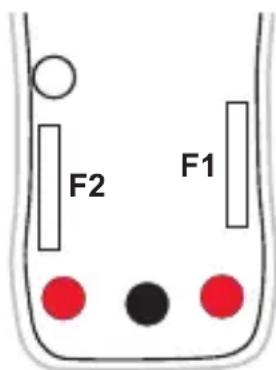
text_image
F2 F15. WARRANTY
Except as otherwise stated, our warranty is valid for twelve months starting from the date on which the equipment was sold. Extract from our General Conditions of Sale provided on request.
The warranty does not apply in the following cases:
■ Inappropriate use of the equipment or use with incompatible equipment;
■ Modifications made to the equipment without the explicit permission of the manufacturer's technical staff;
■ Work done on the device by a person not approved by the manufacturer;
■ Adaptation to a particular application not anticipated in the definition of the equipment or not indicated in the user's manual;
■ Damage caused by shocks, falls, or floods.
Certified to CSA Std. C22.2 No. 61010-1, 61010-2-030, IEC std. 61010-2-033.
Dimensioni (L x l x P) 150 x 74 x 48mm
Peso circa 220g
Caduta 2m.
3.6. SICUREZZA ELETTRICA
Certified to CSA Std. C22.2 No. 61010-1, 61010-2-030, IEC std. 61010-2-033.
3.7. COMPATIBILITÀ ELETTROMAGNETICA
Certified to CSA Std. C22.2 No. 61010-1, 61010-2-030, IEC std. 61010-2-033.