CM605 - Multimeter MULTIMETRIX - Free user manual and instructions
Find the device manual for free CM605 MULTIMETRIX in PDF.

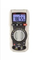
| Product Type | Digital Clamp Multimeter |
| Brand | Multimetrix |
| Model | CM605 |
| Measurement Categories | CAT III 300 V |
| Dimensions (L x W x H) | 202 x 70 x 34 mm |
| Weight (with batteries) | 180 g |
| Power Supply | 2 AAA 1.5 V batteries |
| Battery Life (DC measurement) | 45 hours |
| Display | 4-digit LCD (9,999 counts) |
| Measurement Functions | AC/DC voltage, AC/DC current (up to 100 A), resistance, continuity test |
| Voltage Ranges | 600 V AC/DC |
| Current Ranges | 100 A AC/DC (auto-ranging) |
| Resistance Range | 0 to 10 kΩ |
| Continuity Test | Threshold < 100 Ω, audible signal |
| Analog Output | 10 mV/A (20 kHz ± 3 dB) |
| Special Functions | Data Hold, Peak Hold, Relative Measurement, Auto Power Off (30 min) |
| Safety | Double insulation, overload protection 600 V RMS |
| Operating Conditions | 0 to 40°C, RH < 80%, non-condensing |
| Storage Conditions | -10 to 60°C, RH < 70%, batteries removed |
| Included Accessories | 2 AAA batteries, 2 test lead probes, instruction manual, carrying case |
| Warranty | Against material and workmanship defects (see general terms and conditions) |
| Maintenance | Annual metrological verification recommended; clean with a dry cloth |
| Repairability | Repair by manufacturer or authorized distributor |
Frequently Asked Questions - CM605 MULTIMETRIX
User questions about CM605 MULTIMETRIX
0 question about this device. Answer the ones you know or ask your own.
Ask a new question about this device
Download the instructions for your Multimeter in PDF format for free! Find your manual CM605 - MULTIMETRIX and take your electronic device back in hand. On this page are published all the documents necessary for the use of your device. CM605 by MULTIMETRIX.
USER MANUAL CM605 MULTIMETRIX
text_image
24 HOLD OXYCE
CONDITIONS GENERALES DE GARANTIE ET DE SECURITE
1. PRECAUTIONS D'EMPLOI

AND GUARANTEE CONDITIONS
1. PRECAUTIONS DURING USE

- Please read the safety instructions below before using the instrument to avoid any accidental injuries, such as burns or electric shocks.
- You must observe the instructions preceded by the symbol
1.1 MEASUREMENT CATEGORIES (EN 61010-2-033)
MEASUREMENT CATEGORY II
MEASUREMENT CATEGORY II is applicable to test and measuring circuits connected directly to utilization points (socket outlets and similar points) of the low-voltage MAINS installation. This part of the installation is expected to have a minimum of two levels of overcurrent protective devices between the transformer and the connecting points of the measuring circuit.
Example : measurements on MAINS CIRCUITS of household appliances, portable tools and similar equipment.
MEASUREMENT CATEGORY III
MEASUREMENT CATEGORY III is applicable to test and measuring circuits connected to the distribution part of the building's low-voltage MAINS installation. This part of the installation is expected to have a minimum of one level of over-current protective devices between the transformer and possible connecting points.
Example : measurements on distribution boards (including secondary electricity meters), circuit breakers, wiring, including cables, bus-bars, junction boxes, switches, socket -outlets in the fixed installation, and equipment for industrial use and some other equipment such as stationary motors with permanent connection to the fixed installation.
MEASUREMENT CATEGORY IV
MEASUREMENT CATEGORY IV is applicable to test and measuring circuits connected at the source of the building's low-voltage MAINS installation. This part of the installation could have no over-current protective devices between the transformer and connecting points of the measuring circuit.
Example : measurements on devices installed before the main fuse or circuit breaker in the building installation.
text_image
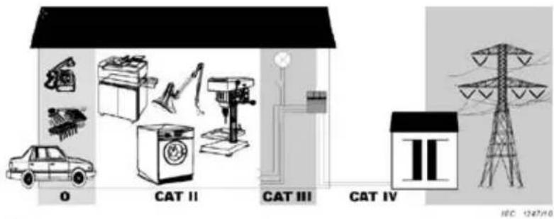
O CAT II CAT III CAT IV II 10C 1247/10Key
O: Other circuits that are not directly connected to MAINS
CAT II MEASUREMENT CATEGORY II
CAT III MEASUREMENT CATEGORY III
CAT IV: MEASUREMENT CATEGORY IV
1.2 NORMS
- Please refer to the norms and installation categories mentioned in the specific instructions for each unit.
- Warning! This instrument is not a voltage or non-voltage detector in the sense of UTE C18510.
1.3 EXPLANATION OF THE SYMBOLS
| Symbol | Signification |
| Instrument with double insulation. | |
| Alternating current (AC). | |
| Direct current (DC). | |
| Warning! Please refer to the operating instructions. | |
| Earth. |
| Symbol | Signification |
| Fuse. | |
| CE approved. | |
| According to WEEE directive2002/96/EC | |
| Do not apply around or remove from hazardous live conductors |
1.4 FOR WORKING SAFELY

This symbol applies to the whole of this section.
- Take particular care with voltages in excess of 30V AC RMS and 50V DC.
- Never work above the indicated maximum voltage ranges, particularly with regards to the Earth.
- When measuring the intensity, always check that the value for the current to be measured is within the measurement range of the instrument. For instruments fitted with fuses, check the fuses' condition before taking any measurements. Only replace worn-out fuses with the fuses recommended in the product's instruction manual.
- Never use the instrument in a damp or dusty environment.
- Never use the instrument without wearing electrician's gloves and the other safety equipment recommended by the legislation.
- Never touch any metal part of the contact points with your finger.
- Check the mechanical and electrical condition of the test leads and the contact points before taking any measurements. Any test leads or contact points that are damaged must be replaced immediately. Never use the instrument if it is damaged.
- Never work with the instrument's rear casing open.
- Never change the batteries while the power cables are connected.
- Do not use the instrument in, or expose it to, direct sunlight, high temperatures or high levels of humidity.
- Do not remove the casing; only the battery compartment cover may be opened.
- Never alter the internal electronic circuits.
1.5 OTHER SAFETY RECOMMENDATIONS
- For instruments of installation categories I and II, never work on equipment that could generate voltage spikes (motors, etc.).
- When measuring in the manual range, always start with the maximum range and then select the most appropriate range.
- First of all connect the black contact point and then the red one.
■ Disconnect the test leads before changing function. - First of all disconnect the red contact point and then the black one.
- Use and install batteries that comply with the instructions in the user's manual for the product you have purchased.
- Check that there is no voltage present before using the ••• and Ω functions.
■ To measure voltage, to measure current:

Please read the safety recommendations before use.
To measure resistance, diode test, Continuity test, to measure frequency / cycle ratio, to replace batteries and fuse.
- To measure capacity there must be no voltage in the circuit and the capacitor to be measured must be discharged.
2. GUARANTEE
The instrument is guaranteed against any material or manufacturing fault in accordance with the General Sales Conditions. During the guarantee period, the instrument may only be repaired by the manufacturer, who reserves the right either to proceed to repair the product or replace it in whole or in part. If any equipment is returned to the manufacturer, the customer is responsible for paying the outward transport costs. The guarantee does not apply in the case of:
- Improper use of the instrument or its use with incompatible equipment.
■ Modification of the instrument without express authorisation from the manufacturer's technical departments.
■ Any work being performed on the instrument by anyone not formally approved by the manufacturer. - Any adaptation for any particular application not provided for in the instrument's definition or the operating instructions.
■ An impact, a fall or drenching in water.
Information and contact details for our After-Sales Services: contact your distributor.
3. UNPACKING AND REPACKING
All the equipment has been checked mechanically and electrically before dispatch. However, you are advised quickly to check for any damage during transport. Should this be the case, inform the freight forwarder immediately of your reservations. If you are sending anything back, please use the original packaging and attach a note indicating the reason for the return.
4. MAINTENANCE
4.1 METROLOGICAL CHECKS
Like all measuring or testing devices, the instrument must be checked regularly.
This instrument should be checked at least once a year. For checking and calibration, contact one of our accredited metrology laboratories (information and contact details available on request), at our Chauvin Arnoux subsidiary or the branch in your country.
4.2 REPAIR
For all repairs before or after expiry of warranty, please return the device to your distributor.
5. STORAGE
Remove the battery or batteries and store them separately if your measuring instrument will not be used for more than 60 days.
6. INTRODUCTION
6.1 THE FRONT FACE
| No. | Function |
| 1. | Black Negative COM terminal (-). |
| 2. | Liquid crystal display 4 digits (9999 points).‘OL’: current and voltage measurements exceed the range. |
| 3. | Trigger for opening the clamp. |
| 4. | Guard: Your hand must be behind this protective guard. |
| 5. | Movable jaws. |
| 6. | Fixed jaws and gap. The conductor must be located in the centre of this area during measurement for maximum accuracy. |
| 7. | HOLDand PEAKbuttons.HOLD: This holds the measurement (Data Hold); theicon appears when the function is activated.Pressing the button again cancels the function.PEAK: displays the peak value; the iconis displayed when the function is activatedfor . Press HOLDduring 2 seconds cancels the function. |
| 8. | Function rotary selector switch.OFF: Multimeter off. : AC current (100 A) : AC current (100 A). : AC voltage (600 V). : DC voltage (600 V). ^- : Resistance and continuity (10 kΩ). |
| 9. | ZERObutton. Measurement is considered as the zero after button is depressed; the iconis displayed.Depress once more time to cancel. |
| 10. | Red positive terminal (+). |
6.2 THE DISPLAY
| No. | Function | No. | Function |
| 11. | Negative value. | 18. | Hold value. |
| 12. | Auto shutdown. | 19. | Continuity. |
| 13. | Low batteries. | 20. | Current. |
| 14. | AC/DC. | 21. | Voltage. |
| 15. | Auto ranges. | 24. | Resistance. |
| 16. | Relative measurement. | 25. | Reading. |
| 17. | Peak value. |
7. USE
7.1 TO USE THE MULTIMETER
Set the selector (8) to any position other than OFF.
7.2 TO STOP THE MULTIMETER
Manual stop
Set the selector (8) to OFF.
Automatic shutdown
The multimeter shuts down automatically 30 minutes after the last measurement.
Cancelling automatic shutdown
-
Set the selector (8) to OFF.
-
Hold down the ZERO button (9) and set the selector (8) to any position other than OFF.
The Ⓧicon disappears and automatic shutdown is deactivated.
Restarting automatic shutdown
-
Set the selector (8) to OFF.
-
Set the selector to any position other than OFF.
The Ⓧ icon appears and automatic shutdown is reactivated.
7.3 TO MEASURE VOLTAGE

Please read the safety recommendations before use.
Automatic measurement ranges 600V DC or AC.
- Set the selector (8) on:
- to measure a DC voltage.
- to measure an AC voltage.
- Insert the black connector into the COM terminal (1), the red connector into the + terminal (10) and take the voltage reading once it has stabilised.
When the AUTO icon (23) is displayed, the multimeter determines the optimum measurement range.
For a continuous voltage, the icon « - » (rep. 11) indicates reversal of the contact points' polarity.
« OL »" indicates that the capacity has been exceeded.
To display the peak value (PEAK), see § 7.9.
To freeze the read value, (DATA HOLD), see § 7.10.
- Set the selector to OFF.
7.4 TO MEASURE DC CURRENT

Please read the safety recommendations before use.
Automatic measurement ranges from 10 A DC to 100 A DC (3 ranges).
-
Set the selector (8) to A.
-
Press the ZERO button (9) to set zero.
The icon △ is displayed; the reading is stored as reference value for subsequent measurement. Press this button again to exit the zero mode.
- Press the trigger (3) to open the clamp (5) and position the conductor in the centre of the clamp (Fig. 3).
NB: never insert two + and - conductors from the same circuit in the clamp; the reading will be zero.
- Take the current reading once it has stabilised.
When AUTO (rep. 15) is displayed, the multimeter determines the optimum measurement range.
The icon « - » (rep. 11) indicates reversal of the contact points' polarity ; refer to the « + » mark graven on the clamp (rep. 6).
If « OL » is displayed, the capacity has been exceeded.
To display the peak value (PEAK), see § 7.9.
To freeze the read value, (DATA HOLD), see § 7.10.
- Open the clamp, release the conductor and set the selector to OFF.
7.5 TO MEASURE THE AC CURRENT
Automatic measurement ranges from 10 A AC to 100 A AC (3 ranges).
-
Set the selector (8) to .
-
Press the trigger (3) to open the clamp (6) and position a conductor in the centre of the clamp (Fig. 3).
NB: never insert two conductors from the same circuit in the clamp; the reading will be zero.
- Take the current reading once it has stabilised.
The AUTO icon (15) is displayed; the multimeter determines the optimum measurement range.
If "OL" is displayed, the capacity has been exceeded.
To display the peak value (PEAK), see § 7.9.
To freeze the read value, (DATA HOLD), see § 7.10.
- Open the clamp, release the conductor and set the selector to OFF.
7.6 TO MEASURE THE RESISTANCE

Please read the safety recommendations before use.
There must be no voltage in the circuit.
Automatic measurement ranges from 0 to 10KΩ (1 range).
-
Set the selector (8) to . Ω
-
Insert the black connector into the COM terminal (1), the red connector into the + terminal (10) and take the reading.
If OL is displayed, the capacity has been exceeded.
When AUTO (rep. 15) is displayed, the multimeter determines the optimum measurement range.
- Set the selector to OFF.
7.7 CONTINUITY TEST

Please read the safety recommendations before use. There must be no voltage in the circuit.
- Set the selector (8) to . Ω·
- Insert the black cable in the COM terminal (1), the red cable in the + terminal (10) and apply the contact points to the circuit to be checked.
The buzzer sounds when the circuit to be checked is DC or has a resistance of less than 100 ± 20 .
- Set the selector to OFF.
7.8 ANALOG OUTPUT SIGNAL

Please read the safety recommendations before use.
-
Set the selector (8) to or .
-
Insert the cable in the COM terminal (1) and another in the + terminal (10). Connect the ends of both cables to an oscilloscope or another multimeter.
- Press the handle (3) to open the clamp (5) and place the conductor in the centre (Fig. 3).
- Close the clamp and read off the analog signal on the oscilloscope or multimeter.
If the signal measured is continuous, the output signal will be DC. If the signal measured is alternating, the output signal will be AC.
- Open the clamp, release the conductor and set the selector to OFF.
7.9 MAX FUNCTION (DISPLAYING THE MAXIMUM VALUE PEAK)
- Set the selector to and press HOLD (7) until the P icon is displayed (17).
- Take the measurement.
The maximum measurement will be updated automatically.
- Press HOLD for 2 seconds to deactivate the PEAK function.
7.10 HOLD FUNCTION (DATA HOLD)
- Set the selector to and press HOLD (7) during 2 seconds.
The icon is displayed (rep. 18).
- Take the measurement.
The measurement is stored
- To deactivate the function, press HOLD during 2 seconds (7). The icon H disappears (rep. 18).
7.11 RELATIVE MEASUREMENT
- Press the ZERO button (9) to activate Zero mode.
The △ icon appears: the value is stored in memory as the reference value for the subsequent measurements. Press the △ ZERO button again (9) to exit Zero mode.
8. TO REPLACE THE BATTERIES

Please read the safety recommendations before use. There must be no voltage in the circuit.
The two batteries type AAA must be replaced when the 📄 icon (13) is displayed:
- Disconnect the contact points.
- Set the selector to OFF.
- Remove the fixing screws and the battery compartment cover. Replace both the 1.5V type AAA batteries, paying careful attention to the polarities.
- Replace the cover and fasten the screws.
NB: Remove the batteries if the multimeter will not be used for a prolonged time.
9.1 GENERAL
| Value measurements | DC and AC voltages, AC and DC current, resistance, continuity test. |
| Display | 4 digits (9 999 points) |
| Polarity indication | “-” sign. |
| Ranges | Automatic range selection. |
| Additional selectable functions | Automatic shutdown (active or not). Display of capacity being exceeded Maximum measurement (Peak). Measurement storage (Data Hold). Zero mode, relative measurements. |
| Battery indication | Low charge battery symbol |
| Sampling frequency | Approx. 2 times per second. |
| Analog output | For ACA and DCA ranges. 10 mV/A (20 kHz ±3 dB). Accuracy: ±4.5% reading +0.5 mV. Output impedance: approx 3 kΩ. Overload protection: 600 V RMS. |
| Use | 0 to 40°C (32°F - 122°F). RH < 80%, no condensation. |
| Storage | -10°C to 60°C (14 – 140°F); RH < 70%, no condensation and with the battery removed. |
| Battery | 2 1.5V AAA type batteries. |
| Autonomy (when measuring Volts DC) | 45 hours with alkaline battery. |
| Dimensions and weight | 202 x 70 x 34 mm / 7.95 x 2.76 x 1.33 inch. (L x | x H). 180 g (with batteries) |
| Pollution level | 2 |
| IEC | IEC 61010-1, IEC 61010-2-033, 300 V, CAT III |
| Delivered with the instrument | 2 1.5V AAA type batteries. Two power cables One set of operating instructions. A carrying case. |
9.2 TECHNICAL DETAILS
Reference conditions: 18°C - 28°C; RH < 80%, no condensation. Norm: NF IEC 61010-1, IEC 61010-2-033, 300 V, CAT III. Accuracy specifications defined as 5% and 100 % on each range. See table on Page 34.
Key
O: Other circuits that are not directly connected to MAINS
CAT II MEASUREMENT CATEGORY II
CAT III. MEASUREMENT CATEGORY III
CAT IV: MEASUREMENT CATEGORY IV
1.2 NORM
7.8 ANALOGES AUSGANGSSIGNAL

Unit 1 Nelson Court – Flagship Square
Shaw Cross Business Park
DEWSBURY- West Yorkshire - WF12 7TH
Tel: 011628 788 888 - Fax: 01628 628 099
MIDDLE EAST - Chauvin Arnoux Middle East
P.O. BOX 60-154
1241 2020 JAL EL DIB (Beirut) - LEBANON
Tel: (01) 89 04 25 - Fax: (01) 89 04 24
CHINA - Shanghai Pu-Jiang - Enerdis Instruments Co Ltd
3 F, Building 1 - N° 381 Xiang De Road
Hongkou District - 200081 SHANGHAI
Tel: +86 21 65 21 51 96 - Fax: +86 21 65 21 61 07
USA - Chauvin Arnoux Inc - d.b.a AEMC Instruments
200 Foxborough Blvd.-Foxborough-MA 02035
Tel: (508) 6982115 - Fax: (508) 698-2118
http://www.chauvin-arnoux.com