DMM54 - Multimeter MULTIMETRIX - Free user manual and instructions
Find the device manual for free DMM54 MULTIMETRIX in PDF.


User questions about DMM54 MULTIMETRIX
0 question about this device. Answer the ones you know or ask your own.
Ask a new question about this device
Download the instructions for your Multimeter in PDF format for free! Find your manual DMM54 - MULTIMETRIX and take your electronic device back in hand. On this page are published all the documents necessary for the use of your device. DMM54 by MULTIMETRIX.
USER MANUAL DMM54 MULTIMETRIX
text_image
Technical diagram of a digital multimeter with numbered parts for identification and assembly reference.1 - Afficheur
■ The meter measures AC/DC Voltage, AC/DC Current, Resistance, Diode Test, Continuity, Capacitance, Frequency and Temperature.
■ The meter also offers a Non-Contact AC Voltage detector.
■ Proper use and care of this meter will provide many years of reliable service.
CONTENTS
- SAFETY......13
1.1. Precaution of use 13
1.2. Input Limits.... 14
1.3. Definition of Symbols....14
- DESCRIPTION....15
2.1. Meter Description 15
2.2. Symbols Used on LCD Display ..... 15
- BUTTON FUNCTIONS....16
3.1. MODE and REL button....16
3.2. RANGE button....16
3.3. MAX/MIN button 16
3.4. HOLD/Backlight button....16
3.5. Auto Power Off 16
3.6. Low Battery Indication 16
- USE17
4.1. AC/DC Voltage Measurement .....17
4.2. Frequency Measurement ..... 17
4.3. AC/DC Current Measurement ..... 17
4.4. Resistance Measurement.....17
4.5. Diode Test.....18
4.6. Continuity Check 18
4.7. Capacitance Measurement ..... 18
4.8. Temperature Measurement 18
4.9. Non-Contact AC Voltage Detection .....18
- SPECIFICATIONS....19
5.1. Specifications ..... 19
5.2. General Specifications ...... 21
- MAINTENANCE......22
6.1. Maintenance and cleaning 22
6.2. Replacing the battery 22
6.3. Replacing The Fuses....22
- WARRANTY....23
1. SAFETY
1.1. PRECAUTION OF USE
This instrument is compliant with safety standard IEC/EN 61010-2-033 or BS EN 61010-2-033 and the leads are compliant with IEC/EN 61010-031 or BS EN 61010-031, for voltages up to 600V in measurement category III.
Failure to observe the safety instructions may result in electric shock, fire, explosion, and destruction of the instrument and of the installations.
■ The operator and/or the responsible authority must carefully read and clearly understand the various precautions to be taken in use. Sound knowledge and a keen awareness of electrical hazards are essential when using this instrument.
If you use this instrument other than as specified, the protection it provides may be compromised, thereby endangering you.
■ Do not use your instrument on networks of which the voltage or category exceeds those stated.
- Observe the environmental conditions of use.
■ Do not use the instrument if it seems to be damaged, incomplete, or poorly closed.
■ Before each use, check the condition of the insulation on the leads, housing, and accessories. Any item of which the insulation is deteriorated (even partially) must be set aside for repair or scrapping.
■ Use leads and accessories rated for voltages and categories at least equal to those of the instrument. If not, an accessory of a lower category lowers the category of the combined device + accessory to that of the accessory.
■ Do not use the instrument in an explosive or dust-laden atmosphere.
■ When handling the test probes, keep your fingers behind the physical guard.
■ Use caution on live circuits, Voltages above 30 VRMS, 42 Vpeak or 60 Vdc pose a shock hazard.
■ Use personal protection equipment systematically.
■ All troubleshooting and metrological checks must be done by competent, accredited personnel.
1.2. INPUT LIMITS
| Function Maximum Input | |
| Voltage AC or DC 600V AC/DC | |
| Frequency, Resistance, Capacitance, Continuity, Diode Test, Temperature | 600V AC/DC |
| Current 10 A AC or DC 10A (protected by fuse) | |
| Current μA/mA AC or DC 500mA (protected by fuse) |
1.3. DEFINITION OF SYMBOLS

WARNING, risk of DANGER! The operator must refer to these instructions whenever this danger symbol appears.
WARNING, risk of electric shock. The voltage applied to parts marked with this symbol may be hazardous.

Equipment protected by double insulation. Battery.


Information or useful tip. Fuse.

The product is declared recyclable following an analysis of the life cycle.


The CE marking indicates compliance with the European Low Voltage Directive (2014/35/EU), Electromagnetic Compatibility Directive (2014/30/EU), and Restriction of Hazardous Substances Directive (RoHS, 2011/65/EU and 2015/863/EU).

The UKCA marking certifies that the product is compliant with the requirements that apply in the United Kingdom, in particular as regards Low-Voltage Safety, Electromagnetic Compatibility, and the Restriction of Hazardous Substances.

The rubbish bin with a line through it indicates that, in the European Union, the product must undergo selective disposal in compliance with Directive WEEE 2019/19/EU. This equipment must not be treated as household waste.

Indicates the terminal(s) so marked must not be connected to a circuit where the voltage with respect to earth ground exceeds the maximum safety rating of the meter.

This symbol indicates a potentially hazardous situation, which if not avoided, could result in death or serious injury.

This symbol indicates a potentially hazardous situation, which if not avoided, may result damage to the product
Definition of measurement categories
■ Measurement category IV corresponds to measurements taken at the source of low-voltage installations.
Example: power feeders, counters and protection devices.
■ Measurement category III corresponds to measurements on building installations.
Example: distribution panel, circuit-breakers, machines or fixed industrial devices
■ Measurement category II corresponds to measurements taken on circuits directly connected to low-voltage installations.
Example: power supply to electro-domestic devices and portable tools.
2. DESCRIPTION
2.1. METER DESCRIPTION
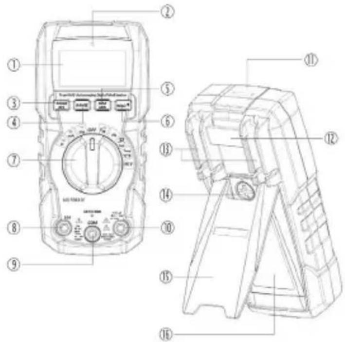
text_image
Technical diagram of a digital multimeter with numbered parts for identification and assembly reference.1-LCD display
2-Non-Contact Voltage Indicator
3-MODE/RELATIVE button
4-RANGE button
5-MAX/MIN button
6-HOLD/Backlight button
7-Function switch
8-10A terminal
9-COM terminal
10-+ (μA/mA) terminal
11-Non-Contact Voltage Detector
12-Lanyard hole
13-Test lead holders
14-Battery cover lock
15-Tilt stand
16-Battery cover
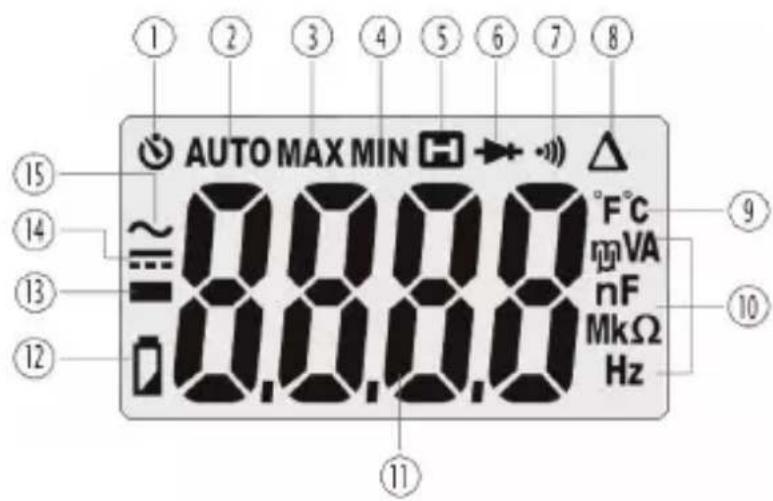
2.2. SYMBOLS USED ON LCD DISPLAY

text_image
AUTO MAX MIN ~ 8.8.8.0 °F°C mA VA nF MkΩ Hz 15 14 13 12 11 9 101-Auto Power Off
2-Auto ranging
3-Maximum
4-Minimum
5-Display Hold
6-Diode Test
7-Continuity
8-Relative mode
9-Degree Celsius/Degree Fahrenheit
10-Units of measure
11-Measurement reading
12-Low battery
13-Minus sign
14-DC
15-AC
3.1. MODE AND REL BUTTON
■ Press the MODE button to select AC/DC voltage, AC/DC current, frequency, resistance, diode test, continuity or capacitance, temperature.
■ Press the REL button for >2 second to turn on or off the Relative function.
■ The Relative function zeros out the reading on the display and stores it as a reference, subsequent readings will be displayed as the relative difference between the actual measurement and the stored reference value.
Note: REL does not work on Frequency, Diode Test, Continuity.
3.2. RANGE BUTTON
When the meter is first turned on, it automatically goes into Auto Ranging.
This automatically selects the best range for the measurements being made and is generally the best mode for most measurements.
For measurement situations requiring that a range be manually selected, perform the following:
■ Press the RANGE button, the AUTO display indicator will turn off.
■ Press the RANGE button to step through the available ranges until you select the range you want.
■ Press and hold the RANGE button for 2 seconds to exit the Manual Ranging mode and return to Auto Ranging.
3.3. MAX/MIN BUTTON
■ Press the MAX/MIN button to activate the MAX/MIN mode, the MAX indicator will appear on the LCD display, the meter will display and hold the maximum reading and will update when a higher maximum occurs.
■ Press the MAX/MIN button again to view the lowest reading, the MIN indicator meter will appear on the LCD display, the meter will display and hold the minimum reading and will update when a lower minimum occurs.
■ Make a long press on the MAX/MIN button to end MAX/MIN and return to normal operation.
Note: The meter does not autorange when the MAX/MIN mode is active, the display will read OL if the range is exceeded. When this occurs, exit MAX/MIN and use the RANGE button to select a high range. MAX/MIN does not work on frequency and capacitance.
3.4. HOLD/BACKLIGHT BUTTON
■ Press the HOLD/ button to turn on or off the HOLD function.
■ Press the HOLD button for >2 second to turn on or off the backlight function.
3.5. AUTO POWER OFF
The auto off feature will turn the meter off after 15 minutes.
To disable the auto power off feature, hold down the MODE button and turn the meter on.
3.6. LOW BATTERY INDICATION
The symbol will appear in the lower left corner of the display when the battery voltage becomes low. Replace the battery when this appears.
4.1. AC/DC VOLTAGE MEASUREMENT
WARNING: Observe all safety precautions when working on live voltages.
CAUTION: Do not measure voltages if a motor on the circuit is being switched ON or OFF. Large voltage surges may occur that can damage the meter.
■ Set the rotatory function switch to the VAC/DC position.
■ To select AC or DC voltage, press the MODE button until the ∼ or === symbol appears on the LCD display.
- Insert the black test lead banana plug into the negative COM terminal; Insert the red test lead banana plug into the + terminal.
■ Touch the black test probe tip to the negative side of the circuit; Touch the red test probe tip to the positive side of the circuit.
- Read the voltage on the LCD display.
■ Press the MODE button to indicate Hz.
- Read the frequency in the display.
4.2. FREQUENCY MEASUREMENT
WARNING: Observe all safety precautions when working on live voltages.
■ Set the rotatory function switch to the Hz position.
- Insert the black test lead banana plug into the negative COM terminal; Insert the red test lead banana plug into the + terminal.
■ Touch the test probe tips to the circuit under test.
- Read the frequency on the display.
4.3. AC/DC CURRENT MEASUREMENT
WARNING: Observe all safety precautions when working on live circuits. Measurements in the 10A range should be limited to 30 seconds maximum every 15 minutes.
■ Insert the black test lead banana plug into the COM terminal.
■ For current measurements up to 10AAC/DC, set the rotary function switch to the 10A position and Insert the red test lead into the 10A terminal.
■ For current measurements up to 400mA AC/DC, set the rotary function switch to the mA position and Insert the red test lead into the + terminal.
■ For current measurements up to 4000μA AC/DC, set the rotary function switch to the μA position and Insert the red test lead into the + terminal.
■ Press the MODE button to select AC or DC current, the ∼ or === symbol will be shown on the LCD display.
■ Remove power from the circuit under test, then open up the circuit at the point where you wish to measure current.
- Touch the black test probe tip to the neutral side of the circuit; Touch the red test probe tip to the "hot" side of the circuit.
■ Apply power to the circuit, Read the current on the LCD display.
4.4. RESISTANCE MEASUREMENT
WARNING: Never test resistance on a live circuit.
■ Set the rotary function switch to the CAP position.
■ Press the MODE button until the symbol appears on the LCD display.
- Insert the black test lead banana plug into the negative COM terminal; Insert the red test lead banana plug into the + terminal.
■ Touch the test lead probes to the component under test, if the component is installed in a circuit, it is best to disconnect one side before testing to eliminate interference with other devices.
- Read the resistance in on the LCD display.
4.5. DIODE TEST
WARNING: Never test resistance on a live circuit.
■ Set the rotary function switch to the Ω↔CAP position.
■ Press the MODE button until the ➤ symbol appears on the LCD display.
- Insert the black test lead banana plug into the negative COM terminal; Insert the red test lead banana plug into the + terminal.
■ Touch the test lead probes to the diode under test.
■ Forward voltage will indicate 0.4 to 0.7V on the LCD display; Reverse voltage will indicate OL; Shorted devices will indicate near 0 and an open device will indicate OL in both polarities.
4.6. CONTINUITY CHECK
WARNING: Never test continuity on a live circuit.
■ Set the rotary function switch to the CAP position.
■ Press the MODE button until the symbol appears on the LCD display.
■ Insert the black test lead banana plug into the negative COM terminal; Insert the red test lead banana plug into the + terminal.
■ Touch the test lead probes to the device or wire under test.
■ A beeper will sound if the resistance is approx. 50 Ω or less and the resistance reading will be shown on the LCD display.
4.7. CAPACITANCE MEASUREMENT
WARNING: To avoid electric shock, disconnect power, remove the batteries and unplug the line cords of the unit under test. Discharge all capacitors before taking any capacitance measurements.
■ Set the rotary function switch to the CAP position.
■ Press the MODE button until the nF symbol appears on the LCD display.
■ Insert the black test lead banana plug into the negative COM terminal; Insert the red test lead banana plug into the + terminal.
■ Touch the test leads to the capacitor to be tested. Wait until the readings settle before ending the test.
- Read the capacitance value in the display.
4.8. TEMPERATURE MEASUREMENT
WARNING: Do not touch the temperature probe to live circuits.
■ Set the function switch to the Temp position.
■ Press the MODE button to indicate °C or °F.
■ Connect the temperature probe to the banana plug adapter, note the - and + markings on the adapter.
■ Connect the adapter to the meter, making sure the - side goes into the COM terminal and the positive side goes into the + terminal.
■ Touch the tip of the temperature probe to the object being measured.
- Read the temperature on the LCD display.
4.9. NON-CONTACT AC VOLTAGE DETECTION
WARNING: Risk of Electrocution. Before use, always test the Voltage Detector on a known live circuit to verify proper operation.
■ Set the rotary function switch to the NCV position.
■ Hold the detector close to the AC voltage being tested.
- If no signal is detected, the LCD will show EF, NCV indicator light doesn't flashes and the buzzer is no sound. - According to the detected signal strength, LCD displays different horizontal lines.
■ When the signal is strongest, LCD displays four horizontal lines, when the signal is weakest, only one line.
■ Meanwhile, NCV indicator light flashes, buzzer make different sound.
Note: The sensing level varies with the distance between the sensing part and the measured AC power cord.
Note: The detector is designed with high sensitivity. Static electricity or other sources of energy may randomly trip the sensor. This is normal operation.

The absence of a voltage indication in the NCV function does not mean that there is no voltage. To confirm the absence of a voltage, use a VAT.

The presence of other voltages nearby can trigger non-contact voltage detection.
5. SPECIFICATIONS
5.1. SPECIFICATIONS
Note: Intrinsic uncertainty is stated at 18 to 28°C (65 to 83°F) and less than 75%RH.
Note: Intrinsic uncertainty is expressed as a percentage of reading (R) plus a number of digits (ct): ±(a% R + b)
| Function Range | Resolution Intrinsic uncertainty | ||
| AC True RMS Voltage | 4.000 V 1 mV ±(1.2% + 3 ct) | ||
| 40.00 V 10 mV | ±(1.2% + 5 ct)400.0 V 10 | ||
| 600 V 1 V | |||
| All AC voltage ranges are specified from 5% of range to 100% of range.AC Voltage Bandwidth: 50 to 60 Hz (All wave); 50 Hz to 1 kHz (Sine wave). | |||
| DC Voltage | 400.0 mV | 0.1 mV | ±(0.5% + 8 ct) |
| 4.000 V 1 mV | |||
| 40.00 V 10 mV | |||
| 400.0 V 100 mV | |||
| 600 V 1 V | |||
| Function Range | Resolution Intrinsic uncertainty | ||
| AC True RMS Current | 400.0 μA 0.1 μA | ±(1.0% + 5 ct)4000 μA 1 | |
| 40.00 mA 10 μA | |||
| 400.0 mA 100 μA | ±(1.2% + 8 ct) | ||
| 4.000 A 1 mA ±(2.0% + 3 ct) | |||
| 10.00 A 10 mA ±(2.0% + 5 ct) | |||
| All AC Current ranges are specified from 5% of range to 100% of range.AC Current Bandwidth: 50 to 60 Hz (All wave); 50 to 400 Hz (Sine wave) | |||
| DC Current | 400.0 μA 0.1 μA | ±(1.0% + 5 ct)4000 μA 1 | |
| 40.00 mA 10 μA | |||
| 400.0 mA 100 μA ±(1.0% + 8 ct) | |||
| 4.000 A 1 mA ±(2.0% + 3 ct) | |||
| 10.00 A 10 mA ±(2.0% + 5 ct) | |||
| Temperature | -18 to 1000°C 1°C ±(1.5% + 5°C) | |
| 0 to 1832°F 1°F ±(1.5% + 9°F) |
| Resistance | 400.0 Ω | 0.1 Ω | ±(1.2% + 5 ct) |
| 4.000 kΩ | 1 Ω | ||
| 40.00 kΩ | 10 Ω | ||
| 400.0 kΩ 100 Ω | |||
| 4.000 MΩ | 1 kΩ | ±(2.5% + 8 ct) | |
| 40.00 MΩ 10 kΩ | ±(3.0% + 8 ct) | ||
| Capacitance | 4.000 nF 0.001 nF | ±(3.5% + 60 ct) | |
| 40.00 nF | 0.01 nF | ±(3.5% + 10 ct) | |
| 400.0 nF 0.1 nF | |||
| 4.000 μF | 1 nF | ±(4.0% + 5 ct) | |
| 40.00 μF | 10 nF | ||
| 400.0 μF | 100 nF | ±(3.5% + 5 ct) | |
| 4.000 mF 1 μF | |||
| Function Range | Resolution Intrinsic uncertainty | ||
| Frequency (Electrical) | 4.000 Hz 0.001 Hz | ±(1.2% + 5 ct) | |
| 40.00 Hz 0.01 Hz | |||
| 400.0 Hz 0.1 Hz | |||
| 4.000 kHz 1 Hz | |||
| 10.00 kHz 10 Hz | |||
Sensitivity: >15V RMS
| Frequency (Electronic) | 2.000 - 4.000 Hz 0.001 Hz | ±(1.2% + 5 ct) | |
| 40.00 Hz 0.01 Hz | |||
| 400.0 Hz 0.1 Hz | |||
| 4.000 kHz 1 Hz | |||
| 40.00 kHz 10 Hz | |||
| 400.0 kHz 100 Hz | |||
| 4.000 MHz 1 kHz | |||
| 10.00 MHz 10 kHz | |||
| >0.8 V RMS while <100kHz; 3 V RMS while >100kHz | |||
5.2. GENERAL SPECIFICATIONS
| Diode Test current approximately 1 mA, open circuit voltage of 2 V typical | |
| Continuity test Audible signal if the resistance is <50 Ω | |
| Display 4000 count LCD | |
| Measurement rate 3 readings per second | |
| Input Impedance >10 MΩ AC and DC Voltage | |
| AC Voltage Bandwidth 50 Hz to 1 kHz | |
| AC Current Bandwidth | 50 to 400 Hz |
| Operating Environment | 5 to 40°C (41 to 104°F) |
| Storage Environment | -10 to 50°C (14 to 122°F) |
| Operating Humidity | Max 80% up to 31°C (87°F) decreasing linearly to 50% at 40°C (104°F) |
| Storage Humidity | <80% |
| Dimensions/ Massa | 154x74x43mm / Approx. 210g (without batteries) |
| Safety | For indoor useClass 2, double insulationComplies with IEC/EN 61010-2-033 or BS EN 61010-2-033 and IEC/EN 61010-031 or BS EN 61010-031 for measurement category III 600V,pollution degree 2. |
6. MAINTENANCE

Except for the batteries and the fuses, the instrument contains no parts that can be replaced by personnel who have not been specially trained and accredited. Any unauthorized repair or replacement of a part by an “equivalent” may gravely impair safety.
6.1. MAINTENANCE AND CLEANING
This Multimeter is designed to provide years of dependable service, if the following care instructions are performed:
- Keep the meter dry, if it gets wet, wipe it off.
■ Use and store the meter in normal temperatures, temperature extremes can shorten the life of the electronic parts and distort or melt plastic parts.
■ Handle the meter gently and carefully, dropping it can damage the electronic parts or the case. - Keep the meter clean, wipe the case occasionally with a damp cloth, do not use chemicals, cleaning solvents, or detergents.
■ Use only fresh batteries of the recommended size and type, remove old or weak batteries so they do not leak and damage the unit.
■ If the meter is to be stored for a long period of time, the batteries should be removed.
6.2. REPLACING THE BATTERY
WARNING: To avoid electric shock, disconnect the test leads from any source of voltage before removing battery cover.
WARNING: To avoid electric shock, do not operate the meter until the battery cover is in place and securely fastened.
■ Rotate the locking screw 180 degrees counterclockwise to open the back cover of battery.
■ Replace old batteries with two AAA 1.5V batteries.
■ Replace and secure the cover of battery.

Spent batteries must not be treated as ordinary household waste. Take them to the appropriate recycling collection point.
6.3. REPLACING THE FUSES
WARNING: To avoid electric shock, disconnect the test leads from any source of voltage before removing the fuse door.
WARNING: To avoid electric shock, do not operate your meter until the fuse cover is in place and fastened securely.
■ Disconnect the test leads from the meter.
■ Rotate the locking screw 180 degrees counterclockwise to open the back cover of battery for the 500mA/600V fast and Remove the rear cover for the 10A/600V fast.
■ Gently remove the old fuse and install the new fuse into the holder.
■ Always use a fuse of the proper size and value (500mA/600V fast blow for the A/mA range or 10A/600V fast blow for the 10A range).
■ Fast Acting fuse 600V 10 A F 6,3 x 32 mm per 10 A range.
■ Fast Acting fuse 600V 500mA F 6,3 x 32 mm per μA/mA range.
- Replace and secure the rear cover.
7. WARRANTY
Except as otherwise stated, our warranty is valid for 24 months starting from the date on which the equipment was sold. The extract from our General Conditions of Sale is available on our website. www.group.chauvin-arnoux.com/en/general-terms-of-sale
The warranty does not apply in the following cases:
■ Inappropriate use of the equipment or use with incompatible equipment;
■ Modifications made to the equipment without the explicit permission of the manufacturer's technical staff;
■ Work done on the device by a person not approved by the manufacturer;
■ Adaptation to a particular application not anticipated in the definition of the equipment or not indicated in the user's manual;
■ Damage caused by shocks, falls, or floods.
text_image
Technical diagram of a digital multimeter with numbered parts for identification and assembly reference.text_image
Technical diagram of a digital multimeter with labeled parts including analog scale, display, and control panel2.2. SIMBOLI UTILIZZATI SUL DISPLAY