DMM210 - Multimeter MULTIMETRIX - Free user manual and instructions
Find the device manual for free DMM210 MULTIMETRIX in PDF.
User questions about DMM210 MULTIMETRIX
0 question about this device. Answer the ones you know or ask your own.
Ask a new question about this device
Download the instructions for your Multimeter in PDF format for free! Find your manual DMM210 - MULTIMETRIX and take your electronic device back in hand. On this page are published all the documents necessary for the use of your device. DMM210 by MULTIMETRIX.
USER MANUAL DMM210 MULTIMETRIX
Industrial Multimeter
Industrie-Multimeter
Multimetro Industriale
Multímetro Industrial
User's manual Chapter II - page 16
1. INSTRUCTIONS GÉNÉRALES....2
AUTO MAX MIN HOLD REL ➤ ◆ ⏰
text_image
DC AC - 8.8.8 mVA MkΩ Hz% -text_image
Diagram of a multimeter with labeled terminals and a voltage source symbol below itnatural_image
Line drawing of a multimeter with circuit board and battery (no text or symbols)natural_image
Line drawing of a digital multimeter with circuit board and power supply (no text or symbols)text_image
Diagram of a multimeter with labeled terminals and electrical connections, including polarity indicatorstext_image
Diagram of a multimeter with labeled terminals and connections, showing measurement setup with negative and positive terminals.text_image
Diagram of a multimeter with labeled components and polarity indicatorsDMM210 9
text_image
Diagram of a multimeter connected to a power source with polarity labels1.1. Precautions and safety measures 17
1.1.1. Before using....17
1.1.3. Symbols....18
1.1.4. Instructions 18
1.1.5. Cleaning 18
1.2. Guarantee....19
1.3. Maintenance 19
1.4. Unpacking - Repacking....19
2. DESCRIPTION 20
2.1 Controls and Terminals....20
2.2 Symbols and Abbreviations....20
3. OPERATING INSTRUCTIONS .....21
3.1 DC voltage measurements .....21
3.2 AC voltage measurements (frequency, duty cycle).....21
3.3 DC current measurements....22
3.4 AC current measurements (frequency, duty cycle)....23
3.5 Resistance measurements 23
3.6 Continuity check....24
3.7 Diode test....24
3.8 Frequency/duty cycle measurements (Electronic)....25
3.9 Autoranging/Manual range selection....25
3.10 MAX/MIN 25
3.11 Relative mode....26
3.12 Backlighting 26
3.13 HOLD....26
3.14 Auto power OFF....26
3.15 Low battery indication 26
4. MAINTENANCE 27
4.1 Battery installation....27
4.2 Replacing the fuses....28
5. TECHNICAL FEATURES....28
1. GENERAL INSTRUCTIONS
1.1. Precautions and safety measures
1.1.1. Before using
You have just acquired a DMM210 meter. Thank you for your confidence. It measures AC/DC Voltage, AC/DC Current, Resistance, Frequency (electrical & electronic), and tests diodes and Continuity. It features a waterproof, rugged design for heavy duty use. Proper use and care of this meter will provide many years of reliable service. This multimeter complies with the IEC 61010-1 and IEC 61010-2-033 standards concerning electronic measurement instruments. For your own safety and to prevent damage to the instrument, follow the instructions in this manual.
Be careful to adhere to storage conditions.
This handheld autonomous instrument was designed for:
* Indoor use
* Use in pollution degree 2 environments
* In altitudes lower than 2,000 metres
* In temperatures ranging from 5°C to 40°C.
It can be used up to 1000 V on category III circuits, or 600 V on category IV circuits.
MEASUREMENT CATEGORIES (IEC 61010-2-033)
CAT II: MEASUREMENT CATEGORY II is applicable to test and measuring circuits connected directly to utilization points (socket outlets and similar points) of the low-voltage MAINS installation. This part of the installation is expected to have a minimum of two levels of overcurrent protective devices between the transformer and the connecting points of the measuring circuit.
Example : measurements on MAINS CIRCUITS of household appliances, portable tools and similar equipment.
CAT III: MEASUREMENT CATEGORY III is applicable to test and measuring circuits connected to the distribution part of the building's low-voltage MAINS installation. This part of the installation is expected to have a minimum of one level of over-current protective devices between the transformer and possible connecting points.
Example : measurements on distribution boards (including secondary electricity meters), circuitbreakers, wiring, including cables, bus-bars, junction boxes, switches, socket -outlets in the fixed installation, and equipment for industrial use and some other equipment such as stationary motors with permanent connection to the fixed installation.
CAT IV: MEASUREMENT CATEGORY IV is applicable to test and measuring circuits connected at the source of the building's low-voltage MAINS installation. This part of the installation could have no overcurrent protective devices between the transformer and connecting points of the measuring circuit.
DMM210 17
Example : measurements on devices installed before the main fuse or circuit breaker in the building installation.
1.1.2. During use
- Never exceed the protection limiting values indicated in the specifications for each type of measurement.
- When the multimeter is connected to the circuits to be measured, do not touch any unused terminals.
- Before changing function, disconnect the measurement leads from the circuit measured.
• Never measure resistances or test diodes, etc., on a live circuit.
1.1.3. Symbols
Refer to the user's manual
Risk of electric shock
Double insulation
WEEE 2002/96/EC directive
1.1.4. Instructions
Before opening the instrument, disconnect it from the circuits to be measured and make sure that you are not charged with static electricity, which could irreparably damage the instrument's internal elements.
1.1.5. Cleaning
Disconnect external circuit leads and turn the instrument off. Clean with a damp cloth and soap. Never use abrasive products or solvents. Make sure the instrument is perfectly dry before using it again.
18 DMM210
1.1.6. Protection factor (PF)/Humid environment
This instrument has a PF67 protection factor, which means that it is extremely waterproof and will not be damaged by water immersion (when turned off). However, the instrument and its accessories must be completely dry (including inside measurement terminals) before being used again.
1.2. Guarantee
This equipment is guaranteed against any material or manufacturing flaws, as specified in the general terms of sale.
During the guarantee period (1 year), the instrument can only be repaired by the manufacturer, who reserves the right to repair the instrument or to exchange all or part of it. If the equipment is returned to the manufacturer, the outgoing transport costs are borne by the customer.
The guarantee is not applicable in the following cases:
- improper use of the equipment or use in conjunction with incompatible equipment;
- modifications to the equipment without the explicit authorisation of the manufacturer's technical department;
- work carried out on the instrument by a person not approved by the manufacturer;
- adaptation for a specific application, not included in user's manual
- knocks, falls or prolonged immersion.
1.3. Maintenance
Return your instrument to your distributor for any work to be done within or outside of the guarantee.
1.4. Unpacking - Repacking
The equipment underwent thorough mechanical and electronic testing before shipment. All the necessary precautions were taken to ensure that you receive the instrument in perfect condition. We recommend you check the equipment quickly on delivery to detect any damage that may have occurred during transport. If there is any damage, inform the carrier immediately. If you ship this instrument on elsewhere, it is preferable to use the original packaging and indicate the reasons for reshipment as clearly as possible in a note enclosed with the equipment.
2. DESCRIPTION
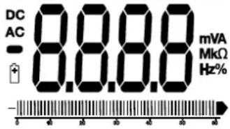
2.1 Controls and Terminals
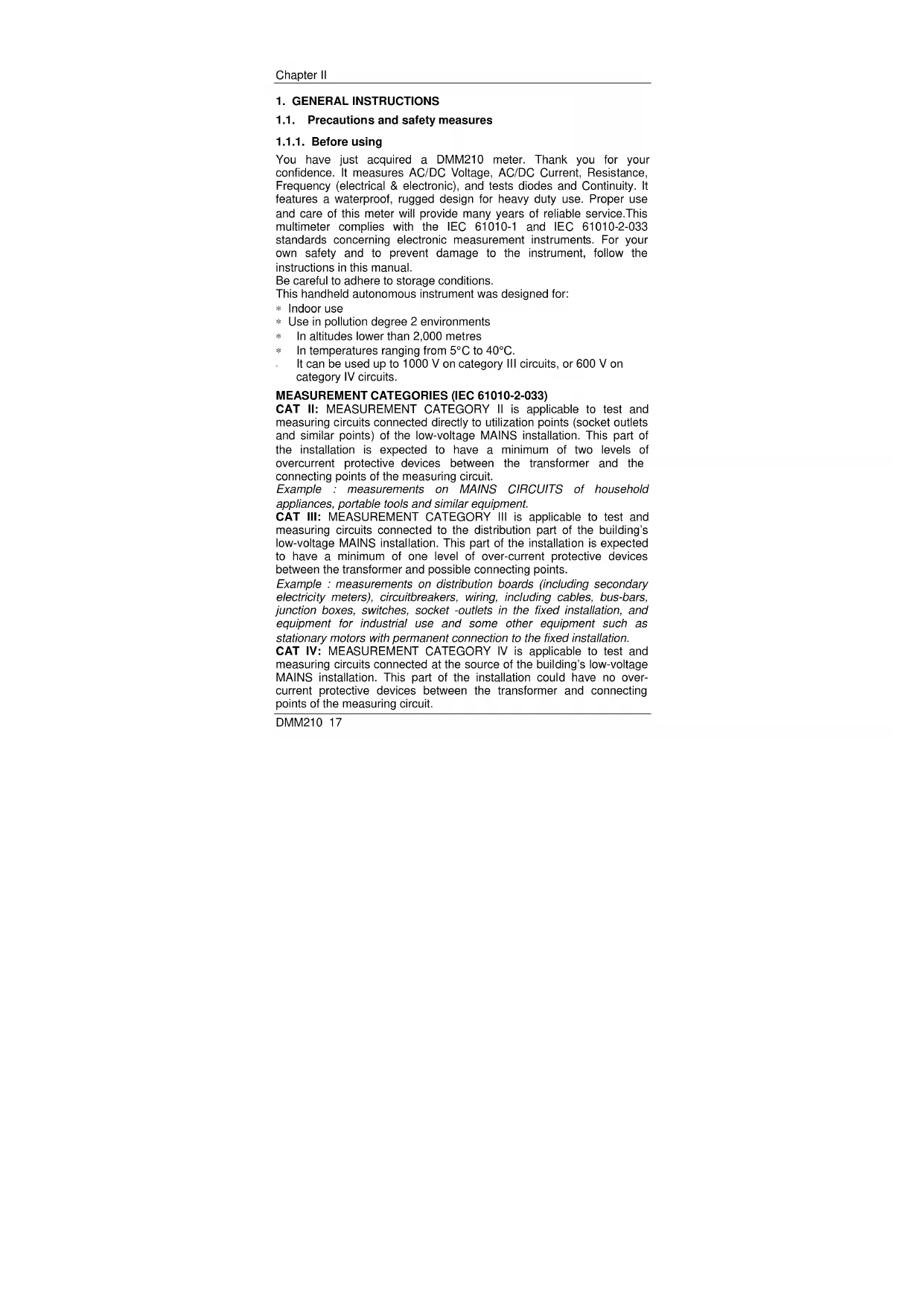
- 6,000 count LCD display
- RANGE button
- Hz and % button
- Mode button
- Function switch
- mA, A and 10A input terminal
- Negative COM input terminal
- V+, Ω positive input terminal
- HOLD and Backlight button
- RELATIVE button
- MAX/MIN button
text_image
1 2 3 4 5 6 7 8 9 10 11 A B C D E F G H I J K L M N O P Q R S T U V W X Y Z A B C D E F G H I J K L M N O P Q R S T U V W X Y ZTilt stand and battery compartment are on rear of unit.
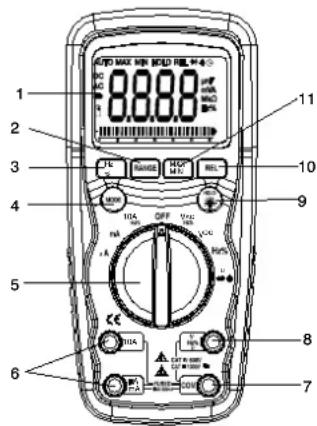
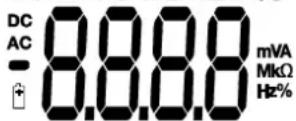
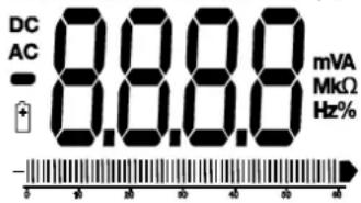
2.2 Symbols and Abbreviations
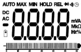
text_image
AUTO MAX MIN HOLD REL DC 8.8.8 mVA AC - 8.8.8 MkΩ Hz%| Auto power off | Hz | Hertz (frequency) | |
| •)) | Continuity | V | Volts |
| Diode test | % | Duty Cycle | |
| Battery status | REL | Relative Measurement | |
| micro ( 10^-6 ) (amps) | AUTO | Autoranging | |
| m | milli ( 10^-3 ) (volts, amps) | HOLD | Display hold |
| A | Amps | MIN | Minimum |
| k | kilo ( 10^-3 ) (ohms) | MAX | Maximum |
| M | mega ( 10^6 ) (ohms) | AC | Alternating current |
| Ohms | DC | Direct current | |
| - | Negative polarity | ||||||||||| | Bargraph |
20 DMM210
3. OPERATING INSTRUCTIONS

Risk of electrocution. High-voltage circuits, both AC and DC, are very dangerous and should be measured with great care.
- Always turn the function switch to the OFF position when the meter is not in use.
- If "OL" appears on the screen during a measurement, the value exceeds the range you have selected. Choose a higher range.
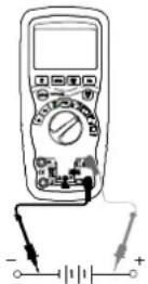
3.1 DC voltage measurements
Do not measure DC voltages if a motor on the circuit is being switched ON or OFF. Voltage surges may occur and damage the meter.
- Set the function switch to the VDC position.
- Insert the black test lead banana plug into the negative COM terminal.
Insert the red test lead banana plug into the positive + terminal. - Apply the test probes to the points of the circuit to be tested.
- The voltage measured is displayed on screen.
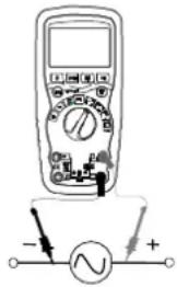
3.2 AC voltage measurements (frequency, duty cycle)

Risk of Electrocution.
The test probes may not be long enough to reach the live parts in certain wall sockets whose contacts are too deeply recessed. As a result, the reading may show 0 volts when the wall socket is live. Make sure the test probes are touching the live parts before assuming that no voltage is present.
Do not measure AC voltages if a motor on the circuit is being switched ON or OFF. Voltage surges may occur that can damage the multimeter.
- Set the function switch to the VAC/Hz/% position.
- Insert the black test lead banana plug into the negative COM terminal. Insert red test lead banana plug into the positive + jack.
- Apply the test probes to the points of the circuit to be tested
- The voltage measured is displayed on screen
- Press the Hz % button to display "Hz".
- The frequency measured is displayed on screen.
- Press the Hz % button again to display "%".
- The duty cycle is displayed in percentage
text_image
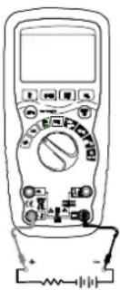
Diagram of a multimeter with an analog voltmeter connected to a power supply, showing polarity and current direction3.3 DC current measurements
Do not make 20 A current measurements for longer than 30 s. Exceeding 30 seconds may cause damage to the meter and/or the test leads.
- Insert the black test lead banana plug into the negative COM terminal.
- For DC current measurements up to 6000 A, set the function switch to the A position and insert the red test lead banana plug into the A/mA terminal.
- For DC current measurements up to 600mA, set the function switch to the mA position and insert the red test lead banana plug into the μA/mA terminal.
- For DC current measurements up to 20A, set the function switch to the 10A position and insert the red test lead banana plug into the 10A terminal.
- Press the MODE button to display "DC" on screen.
- Apply the test probes to the points of the circuit to be tested.
- Apply power to the circuit.
-
The current measured is displayed on screen
-
Remove power from the circuit to be tested, then open the circuit at the point where you wish to measure the current.
text_image
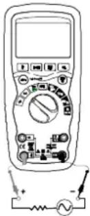
Diagram of a multimeter with labeled function dial and electrical connections3.4 AC current measurements (frequency, duty cycle)
Do not make 20 A current measurements for longer than 30 s. Exceeding 30 seconds may cause damage to the meter and the test leads.
- Insert the black test lead banana plug into the negative COM terminal.
- For AC current measurements up to 6000μA, set the function switch to the μA position and insert the red test lead banana plug into the μA/mA terminal.
- For AC current measurements up to 600mA, set the function switch to the mA position and insert the red test lead banana plug into the μA/mA terminal.
-
For AC current measurements up to 20A, set the function switch to the 10A position and insert the red test lead banana plug into the 10A terminal.
-
Press the MODE button to display "AC" on the screen.
-
Remove power from the circuit to be tested, then open the circuit at the point where you wish to measure the current.
-
Apply the test probes to the points of the circuit to be tested.
-
Apply power to the circuit.
-
The current measured is displayed on screen.
-
Press the Hz/% button to display "Hz".
-
The frequency measured is displayed on screen.
-
Press the Hz/% button again to indicate “%”.
-
The duty cycle is displayed in percentage.
-
Press the Hz/% button to return to current measurement.
text_image
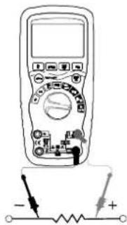
Diagram of a multimeter with labeled terminals and electrical connections, including a battery and switch.3.5 Resistance measurements
To eliminate any risk of deterioration, disconnect power to the circuit to be tested before making any resistance measurements.
- Set the function switch to the → position.
- Insert the black test lead banana plug into the negative COM terminal.
- Insert the red test lead banana plug into the positive + terminal.
- Press the MODE button to indicate "Ω".
- Apply the test probes to the circuit to be tested. It is best to disconnect one side of the part to be measured so the rest of the circuit will not interfere with the measurement. Read in the display.
text_image
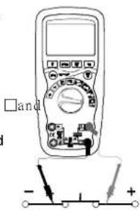
Diagram of a multimeter with labeled terminals and electrical circuit symbols, showing polarity indicators3.6 Continuity check
To eliminate any risk of deterioration, disconnect power to the circuit to be tested before making any continuity measurements.
- Set the function switch to the position.
- Insert the black lead banana plug into the negative COM terminal. Insert the red test lead banana plug into the positive + terminal.
- Press the MODE button to display "☐" " ☐" screen
- Apply the test probes to the circuit to be tested
- Any resistance greater than 100 Ω stops the sound alert emitted by the instrument. If the circuit is open, the screen displays "OL".
text_image
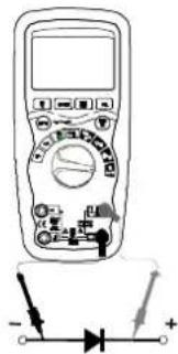
□and - 1 +3.7 Diode test
To eliminate any risk of deterioration, disconnect power to the circuit to be tested before making any diode measurement.
- Set the function switch to the position.
- Insert the black test lead banana plug into the negative COM terminal and the red test lead banana plug into the positive + terminal.
- Press the MODE button to display ➤ and V □□□□ on screen.
- Apply the test probes to the terminals of the diode to be tested. Forward voltage will typically indicate 0.400 to 0.700V.
text_image
Diagram of a multimeter with labeled terminals and a diode symbol, showing polarity indicators.Reverse voltage is indicated by "OL". Shorted elements will indicate near 0V and an open element will indicate "OL" in both polarities.
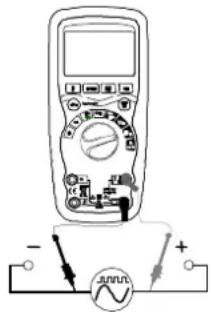
3.8 Frequency/duty cycle measurements (Electronic)
- Set the function switch to the "Hz %" position.
- Press the Hz/% button to display "Hz".
- Insert the black lead banana plug into the negative COM terminal and the red test lead banana plug into the positive + terminal.
- Apply the test probes to the points of the circuit to be tested.
- The frequency measured is displayed on screen.
- Press the Hz/% button again to display “%”.
- The duty cycle is displayed in percentage.
text_image
Diagram of a multimeter connected to a voltage meter with polarity labels3.9 Autoranging/Manual range selection
When the multimeter is first turned on, it automatically goes into Autoranging and automatically selects the best range for the measurements being made. This is generally the best mode for most measurements. When manual range selection is necessary, proceed as follows:
- Press the RANGE key. The "AUTO" display will turn off.
- Press the RANGE key several times to scroll through the available ranges until the range you want is displayed.
- To exit Manual selection mode and return to Autoranging, press and hold down the RANGE key for 2 seconds.
Manual ranging does not apply to frequency measurements.
3.10 MAX/MIN
When using the MAX/MIN function in Autoranging mode, the multimeter will "lock" into the range that is used when MAX/MIN is activated. If a MAX/MIN reading exceeds that range, an "OL" will be displayed. Select the adequate range BEFORE entering MAX/MIN mode.
-
Press the MAX/MIN key to activate the MAX/MIN measurement mode. The "MAX" is displayed. The meter will display and hold the maximum measurement until a new maximum value is measured.
-
Press the MAX/MIN key again to display the "MIN" icon. The multimeter will display and hold the minimum measurement until a new minimum value is measured.
- To exit MAX/MIN mode press and hold the MAX/MIN key for 2 seconds.
3.11 Relative mode
Relative mode enables relative measurement results to be obtained in relation to a stored reference value. The displayed value is the difference between the stored reference value and the value measured.
- Perform the measurement as described in the operating instructions.
- Press the REL button to store the displayed measurement. The "REL" indicator is displayed.
- The display will now indicate the difference between the stored reference value and the value measured.
- Press the REL button to exit relative mode.
Relative mode does not apply to frequency measurements.
3.12 Backlighting
Press and hold down the HOLD key for >1 second to turn on or off the screen's backlighting. The backlighting will automatically turn off after 10 seconds.
3.13 HOLD
The hold function freezes display of the current value. Briefly press the HOLD key to activate or disable the HOLD function.
3.14 Auto power OFF
The auto off function turns off the multimeter after 15 minutes. To disable this function, hold down the MODE button when turning on the multimeter.
3.15 Low battery indication
The 📋 icon will appear in the lower left corner of the screen when the battery voltage becomes low. Replace the battery when this icon is displayed.
4. MAINTENANCE
To avoid electric shocks, disconnect the measurement leads from any source of voltage before opening the instrument or battery compartment. Do not use the instrument when it is open or without locking the battery compartment cover.
This multimeter is designed to provide years of reliable service, if the following care instructions are followed:
- Keep the meter dry. If it gets wet, wipe it dry.
- Use and store the multimeter in normal temperatures. Extreme temperatures can shorten the life of the electronic parts and distort or melt plastic parts.
- Handle the multimeter gently and carefully. Dropping it can damage the electronic parts or the case.
- Keep the multimeter clean. Wipe the case occasionally with a damp cloth. DO NOT use chemical substances, cleaning solvents or detergents.
- Use only new batteries of the recommended size and type. Remove the old or used battery so it does not leak and damage the instrument.
- If the multimeter is to be stored for a long period of time, the battery should be removed to prevent damage to the unit.
4.1 Battery installation

To avoid electric shocks, disconnect the measurement leads any source of voltage before removing the battery cover.
- Turn power off and disconnect the test leads from the multimeter.
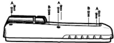
- Open the battery cover on the rear panel by removing the two screws (B) using a head screwdriver.
- Insert the battery into battery holder, observing the correct polarity.
- Put the battery cover back in place. Screw back down.
If your multimeter is not working properly, check the fuses and batteries to make sure that they are still good and that they are properly inserted.
text_image
A B A B A
natural_image
Cross-sectional diagram of a mechanical device with labeled parts F1 and F2 (no text or symbols beyond labels)4.2 Replacing the fuses
To avoid electric shocks, disconnect the test leads from any source of voltage before removing the battery cover.
- Disconnect the test leads from the multimeter.
- Remove the battery cover (two "B" screws) and the battery.
- Remove the six "A" screws securing the rear panel.
- Gently remove the old fuse and install the new fuse.
- Always use a fuse of the proper size and value (0.8A/1000V fast blow for the 600mA range [SIBA 70-172-40], 10A/1000V fast blow for the 20A range [SIBA 50-199-06]).
- Replace and secure the rear panel, battery and battery cover.
5. TECHNICAL FEATURES
| Function | Range | Resolution | Accuracy | Protection | |
| DC Voltage | 600 mV | 0,1 mV | ±(0,09 % R + 2 D) | 1 000 V | |
| 6V | 0,001 V | ||||
| 60 V | 0,01 V | ||||
| 600 V | 0,1 V | ||||
| 1 000 V | 1 V | ±(0,15% R + 2 D) | |||
| AC Voltage | 50 to 60 Hz | 40Hz-1kHz | |||
| 6 V | 0,001 V | ±(1,0% R + 3 D) | ±(2,0% R + 3 D) | 1 000 V | |
| 60 V | 0,01 V | ||||
| 600 V | 0,1 V | ||||
| 1 000 V | 1 V | ±(1,2% R + 3 D) | ±(2,5% R + 3 D) | ||
| Accuracy for 5 % to 100 % of range | |||||
| DC Current | 600 μA | 0,1μA | ±(1,0 % R + 3 D) | Fuse HBC 800mA/1000V | |
| 6 000 μA | 1 μA | ||||
| 60 mA | 0,01 mA | ||||
| 600 mA | 0,1 mA | ||||
| 6 A | 0,001 A | ±(1,5 % R + 3 D) | Fuse HBC 10A/1000V | ||
| 10 A | 0,01 A | ||||
| (20 A : 30 s max. with reduced accuracy) | |||||
| AC Current | 40 Hz to 1 kHz | ||||
| 600 μA | 0,1μA | ±(1,5 % R + 3 D) | Fuse HBC 800mA/1000V | ||
| 6 000 μA | 1 μA | ||||
| 60 mA | 0,01 mA | ||||
| 600 mA | 0,1 mA | ||||
| 6 A | 0,001 A | ±(2,0 % R + 3 D) | Fuse HBC 10A/1000V | ||
| 10 A | 0,01 A | ||||
| (20 A : 30 s max. with reduced accuracy) | |||||
| Accuracy for 5 % to 100 % of range | |||||
R: reading; D: digits
Accuracy is valid from 18 °C to 28°C, RH < 75%.
Chapter II
| Function | Range | Resolution | Accuracy | Authorized overload protection |
| Resistance | 600 Ω | 0,1 Ω | ±(0,3 % R + 4 D) | 1 000 V |
| 6 kΩ | 0,001 kΩ | |||
| 60 kΩ | 0,01 kΩ | |||
| 600 kΩ | 0,1 kΩ | |||
| 6 MΩ | 0,001 MΩ | |||
| 60 MΩ | 0,01 MΩ ± | (0,5 % R + 20 D) | ||
| Frequency (electronic) | 9,999 Hz | 0,001 Hz | ±(0,1 % R + 1 D) | 1 000 V |
| 99,99 Hz | 0,01 Hz | |||
| 999,9 Hz | 0,1 Hz | |||
| 9,999 kHz | 0,001 kHz | |||
| 99,99 kHz | 0,01 kHz | |||
| 999,9 kHz | 0,1 kHz | |||
| 9,999 MHz | 0,001 MHz | |||
| Sensitivity :0.8 Vrms min. @ 20 % to 80 % duty cycle and F < 100 kHz;5 Vrms min. @ 20 % to 80 % duty cycle and F > 100 kHz | ||||
| Frequency (electrical) | 10,00-400 Hz | 0,01 Hz | ±(0,5 % R) | 1 000 V |
| Sensitivity : 15 Vrms | ||||
| Duty cycle | 0,1 to 99,9 % | 0,1 % | ±(1,2 % R + 2 D) | 1 000 V |
| Pulse width : 100 μs - 100 msFrequency : from 5 Hz to 150 kHz | ||||
Accuracy features include two elements:
(% R reading): accuracy of the measurement circuit
(+D figures): ADC accuracy
| Case | Double molded, waterproof IP67 |
| Shock (Drop Test) | 2 m |
| Diode Test | Test current of 0.9mA max.,open circuit voltage 2.8V DC typical |
| Continuity Check | Sound alerts stops if:resistance >100 Ω,test current < 0.35mA |
| Input Impedance >10MΩ V = and V ≈ | |
| AC Response Averaged | |
| ACV Bandwidth 40Hz to 1kHz | |
| Peak Factor ≤ 3 at full scale up to 500V, decreasinglinearly to ≤1.5 at 1000V | |
| Display | 6,000 count backlit LCD with bargraph |
| Overrange value | “OL” is displayed |
| Auto Power Off | 15 min. (approx.) with disable feature |
| Polarity Automatic, no indication for positive values;minus (-) sign for negative values | |
| Measurement Rate | 2 measures per second, nominal |
| Low Battery Indication | “ ” is displayed if battery voltage drops below operating voltage |
| Battery | 9 V battery (6LF22) |
| Fuses | mA, μA ranges: 0.8A/1000V ceramic fast blowA range: 10A/1000V ceramic fast blow |
| Operating Temperature | 5°C to 40°C |
| Storage Temperature | -20°C to 60°C |
| Operating Humidity | max 80% up to 31°C decreasing linearly to 40°C |
| Storage Humidity | < 80% |
| Operating Altitude | 2000 m max. |
| Weight | 342 g incl. holster |
| Dimensions | 187 x 81 x 50mm incl. holster |
| Safety | In compliance with IEC61010-1and IEC 61010-2-033Double isolationInstallation category: IIIRated voltage: 1000 VPollution degree: 2 |
Inhalt
1. ALLGEMEINE HINWEISE....32
text_image
Diagram of a multimeter with labeled terminals and a voltage source symbol below itnatural_image
Line drawing of a multimeter with circuit components and power supply (no text or symbols)natural_image
Illustration of a multimeter with circuit connections and a battery (no text or symbols)text_image
Diagram of a multimeter with labeled terminals and polarity indicators showing measurement points3.7 Diodentest

text_image
Diagram of a multimeter with labeled terminals and a diode symbol below, showing electrical connections.text_image
Diagram of a multimeter connected to a power supply with labeled terminals and current direction indicatorsnatural_image
Line drawing of a device with labeled points (A, B, C) and directional arrows indicating movement or orientation (no text or symbols present)
AUTO MAX MIN HOLD REL
text_image
Diagram of a multimeter with labeled terminals and a voltmeter connected to a power sourcetext_image
Diagram of a multimeter with labeled buttons and a battery, showing measurement ranges and function indicators.natural_image
Line drawing of a multimeter with circuit board and power supply (no text or symbols)text_image
Diagram of a multimeter with labeled terminals and electrical connections, including a battery symbol and polarity indicators.text_image
Diagram of a multimeter with labeled terminals and measurement markings, showing connections to ground points.text_image
Diagram of a multimeter with labeled terminals and electrical connections, including a battery symbol and polarity indicators.DMM210 55
Capitolo IV
AUTO MAX MIN HOLD REL ➕ ◆ ⏰
text_image
DC AC - 8.8.8 mVA MkΩ Hz% -text_image
Diagram of a multimeter with labeled terminals and a voltmeter connected to positive and negative terminals3.3 Medidas de corriente continua
natural_image
Illustration of a digital multimeter with an analog circuit connected to its terminals (no text or symbols visible)natural_image
Line drawing of a multimeter with circuit components and a power supply (no text or symbols)text_image
Diagram of a multimeter connected to a power supply with labeled terminals and connection pointsnatural_image
Technical line drawing of a mechanical device with labeled sections F1 and F2 (no text or symbols beyond labels)UK - Unit 1 - Nelson Ct - Flagship Sq - Shaw Cross Business Pk - Dewsbury
West Yorkshire - WF12 7 ^TH - Tél : 01924 460 494 - Fax : 01924 455 328
Middle East - P.O BOX 60-154 - 1241 2020 Jal el dib- BEIRUT