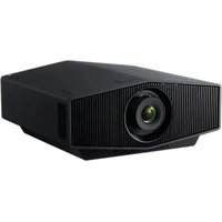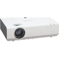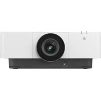
VPLFHZ80 - Projector SONY - Free user manual and instructions
Find the device manual for free VPLFHZ80 SONY in PDF.



| Product type | Projector |
| Brand | Sony |
| Model | VPLFHZ80 |
| Light source | Laser (laser diode array, 95 W, 20 diodes) |
| Wavelength | 449 - 461 nm |
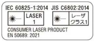
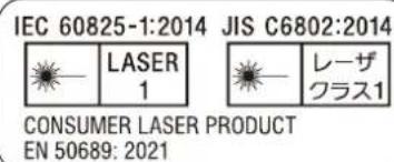
| Laser class | IEC 60825-1:2014 Class 1 |
| Visual safety | RG2 IEC 62471-5:2015 - Do not look into the lens |
| Lens | Interchangeable (optional accessory) |
| Lens shift (Lens Shift) | Electric |
| Zoom | Electric or manual depending on lens |
| Focus | Electric or manual depending on lens |
| Brightness sensor | Yes, for automatic image correction |
| Automatic filter cleaning | Yes |
| Connectivity | HDMI, LAN, HDBaseT |
| Power supply | Mains (power cord supplied) |
| Dimensions (W x H x D) | 460 x 169 x 516.5 mm |
| Network features | Control via web browser, control protocol |
| High altitude mode | Yes, adjustable in menu |
| Air filter | Cleanable and replaceable |
| Included accessories | Remote control (RM-PJ30), AA batteries (x2), power cord, plug holder |
| Menu languages | French, English, etc. |
Frequently Asked Questions - VPLFHZ80 SONY
User questions about VPLFHZ80 SONY
0 question about this device. Answer the ones you know or ask your own.
Ask a new question about this device
Download the instructions for your Projector in PDF format for free! Find your manual VPLFHZ80 - SONY and take your electronic device back in hand. On this page are published all the documents necessary for the use of your device. VPLFHZ80 by SONY.
USER MANUAL VPLFHZ80 SONY
© 2021 Sony Corporation

このマニュアルについて
natural_image
Line drawing of a steam machine emitting smoke, with no text or symbols present.natural_image
Simple line drawing of a building on a roof with smoke and a prohibition symbol (no text or labels)
禁止
熱感知器や煙感知器のそばに設置しない
natural_image
Diagram of a front-mounted air conditioner unit with ventilation grilles and control panel (no text or labels)① クラス1ラベル
text_image
IEC 60825-1:2014 JIS C6802:2014 LASER 1 LEーザ クラス1 CONSUMER LASER PRODUCT EN 50689: 2021光源の仕様
VPL-FHZ85
natural_image
Illustration of a steam rising from a chimney to a printer with smoke, no text or symbols presenttext_image
Diagram showing connection between a laptop and an HDMI device via USB port, with labeled ports and connection point.HDMI ケーブル(別売)
ご注意
text_image
Operation Language English Menu Position Bottom Left Status On IR Receiver Front & Rear ID Mode All Security Lock Off Control Key Lock Off Lens Control On Menu Settings Lock Set Password OK Select Sat Set Backnatural_image
Two grayscale images showing a table with fruit and grapes, one before and after transformation (no text or symbols)電動フォーカスレンズを装着しているとき
natural_image
Black-and-white photo of assorted fruits including grapes, apples, and a rainbow on a white surface, with no visible text or symbols.natural_image
Diagram of a projector with a circular base and internal components, showing no text or symbols.ご注意
natural_image
Line drawing of a car air conditioner panel with two circular insets showing the control panel (no text or symbols)natural_image
Line drawing of a projector with a circular vent and scroll wheel (no text or symbols)ご注意
This Setup Guide explains the safety precautions for using of this unit, how to install the unit, and the initial setup.
Step 1
Preparing Page 35
Step 2
Connecting Page 36
Step 3
Projecting......Page 39
Indicators...... Page 42
Cleaning the Air Filter......Page 44
Replacing the Projection Lens......Page 45
Dimensions......Page 46
Manuals supplied

Setup Guide (this document)
Explains the safety precautions, installation method, and initial setup for this unit.
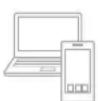
Help Guide (Web operating instructions)
Explains the features of the unit and how to use in detail. You can view the Help Guide on a smartphone or computer.
https://rd1.sony.net/help/vpl/fhz85/en/

English
Before operating the unit, please read this manual thoroughly and retain it for future reference.
When using the product, do not use it for purposes other than those described in the instruction manual.
WARNING
To reduce the risk of fire or electric shock, do not expose this apparatus to rain or moisture. To avoid electrical shock, do not open the cabinet. Refer servicing to qualified personnel only.
WARNING
This apparatus must be earthed.
CAUTION
- Danger of explosion if battery is incorrectly replaced. Replace only with the same or equivalent type recommended by the manufacturer.
- When you dispose of the battery or the product, you must obey the law in the corresponding area or country. Do not dispose of the battery or the product in a fire or a hot oven, or mechanically crush or cut the battery. It may explode or cause a fire. Do not subject the battery to extremely low air pressure that may result in an explosion or the leakage of flammable liquid or gas.
- Do not place the battery in a high temperature place, such as under direct sunlight or near fire. It may ignite, explode, or cause a fire. Do not immerse or wet the battery in water or seawater. This may cause an electric shock.
WARNING
When installing the unit, incorporate a readily accessible disconnect device in the fixed wiring, or connect the power plug to an easily accessible socket-outlet near the unit. If a fault should occur during operation of the unit, operate the disconnect device to switch the power supply off, or disconnect the power plug.
CAUTION
For safety, do not connect the connector for peripheral device wiring that might have excessive voltage to the following port:
• LAN
WARNING
- Use the approved Power Cord (3-core mains lead) / Appliance Connector / Plug with earthing-contacts that conforms to the safety regulations of each country/region if applicable.
- Use the Power Cord (3-core mains lead) / Appliance Connector / Plug conforming to the proper ratings (Voltage, Ampere).
If you have questions on the use of the above Power Cord / Appliance Connector / Plug, please consult a qualified service personnel.
IMPORTANT
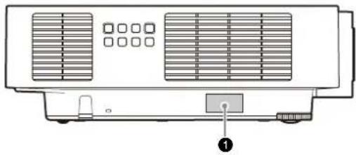
The nameplate is located in the following location on the unit.
- Bottom
For the customers in the U.S.A.
This equipment has been tested and found to comply with the limits for a Class A digital device, pursuant to part 15 of the FCC Rules. These limits are designed to provide reasonable protection against harmful interference when the equipment is operated in a commercial environment. This equipment generates, uses and can radiate radio frequency energy and, if not installed and used in accordance with the instruction manual, may cause harmful interference to radio communications. Operation of this equipment in a residential area is likely to cause harmful interference in which case the user will be required to correct the interference at his own expense.
You are cautioned that any changes or modifications not expressly approved in this manual could void your authority to operate this equipment.
All interface cables used to connect the equipment to peripherals must be shielded type to comply with EMC standard(s) and to prevent undesired operation due to radiated emissions. When cables are supplied, always use them for this purpose.
If you have any questions about this product, you may call:
Sony Customer Information Service Center 1-800-222-7669 or http://www.sony.com/
Supplier's Declaration of Conformity
Trade Name : SONY
Model : VPL-FHZ85/VPL-FHZ80
Responsible party : Sony Electronics Inc.
Address 16535 Via Esprillo, San
Diego, CA 92127 U.S.A.
Telephone Number: 858-942-2230
This device complies with part 15 of the FCC Rules.
Operation is subject to the following two conditions: (1) This device may not cause harmful interference, and (2) this device must accept any interference received, including interference that may cause undesired operation.
For the customers in Canada
CAN ICES-003(A) / NMB-003(A)
WARNING
Operation of this equipment in a residential environment could cause radio interference.
For the customers in Europe
This apparatus shall not be used in the residential area.
CAUTION
The following size and number of batteries are required for the remote control.
- Size: AA (R6)
• Number of battery(ies): Two pieces
To avoid risk of explosion, use only the following type of battery.
- Manganese or alkaline batteries

This symbol is intended to alert the user to the presence of important operating and maintenance (servicing) instructions in the literature accompanying the appliance.
For the customers in the U.S.A.
CAUTION
Use of controls or adjustments or performance of procedures other than those specified herein may result in hazardous radiation exposure.
CAUTION
Do not look into the lens while in use.
CAUTION
Do not allow children to operate this product without supervision.
CAUTION
The use of optical instruments with this product will increase eye hazard.
For the customers in other countries/regions
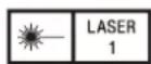
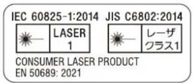
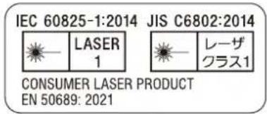
IEC 60825-1:2014
CLASS 1 LASER PRODUCT
• This product complies with EN60825-1:2014+A11:2021.
• This product complies with EN50689:2021.
- This product is designed to project images on a wall or screen.
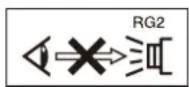
As with any bright light source, do not stare into the beam, RG2 IEC 62471-5:2015.
WARNING: Do not look into the lens while in use.
Caution
Use of controls or adjustments or performance of procedures other than those specified herein may result in hazardous radiation exposure.
Caution
The use of optical instruments with this product will increase eye hazard.
LASERPRODUKT AV KLASS 1
Never allow children to stare into the projector beam at any distance from the projector.
CAUTION
Do not turn on the projector with the remote commander while in front of the projection lens.
CAUTION
Avoid the use of optical aids such as binoculars or telescopes inside the beam.
For the customers in the U.S.A.
SONY LIMITED WARRANTY - Please visit http://www.sony.com/psa/warranty for important information and complete terms and conditions of Sony's limited warranty applicable to this product.
For the customers in Canada
SONY LIMITED WARRANTY - Please visit http://www.sonybiz.ca/pro/lang/en/ca/article/resources-warranty for important information and complete terms and conditions of Sony's limited warranty applicable to this product.
For the customers in Europe
Sony Professional Solutions Europe - Standard Warranty and Exceptions on Standard Warranty. Please visit https://pro.sony/support-services/primesupport/support-professional-solutions-europe-standard-product-warranty for important information and complete terms and conditions.
For the customers in Korea
SONY LIMITED WARRANTY - Please visit http://bpeng.sony.co.kr/handler/BPAS-Start for important information and complete terms and conditions of Sony's limited warranty applicable to this product.
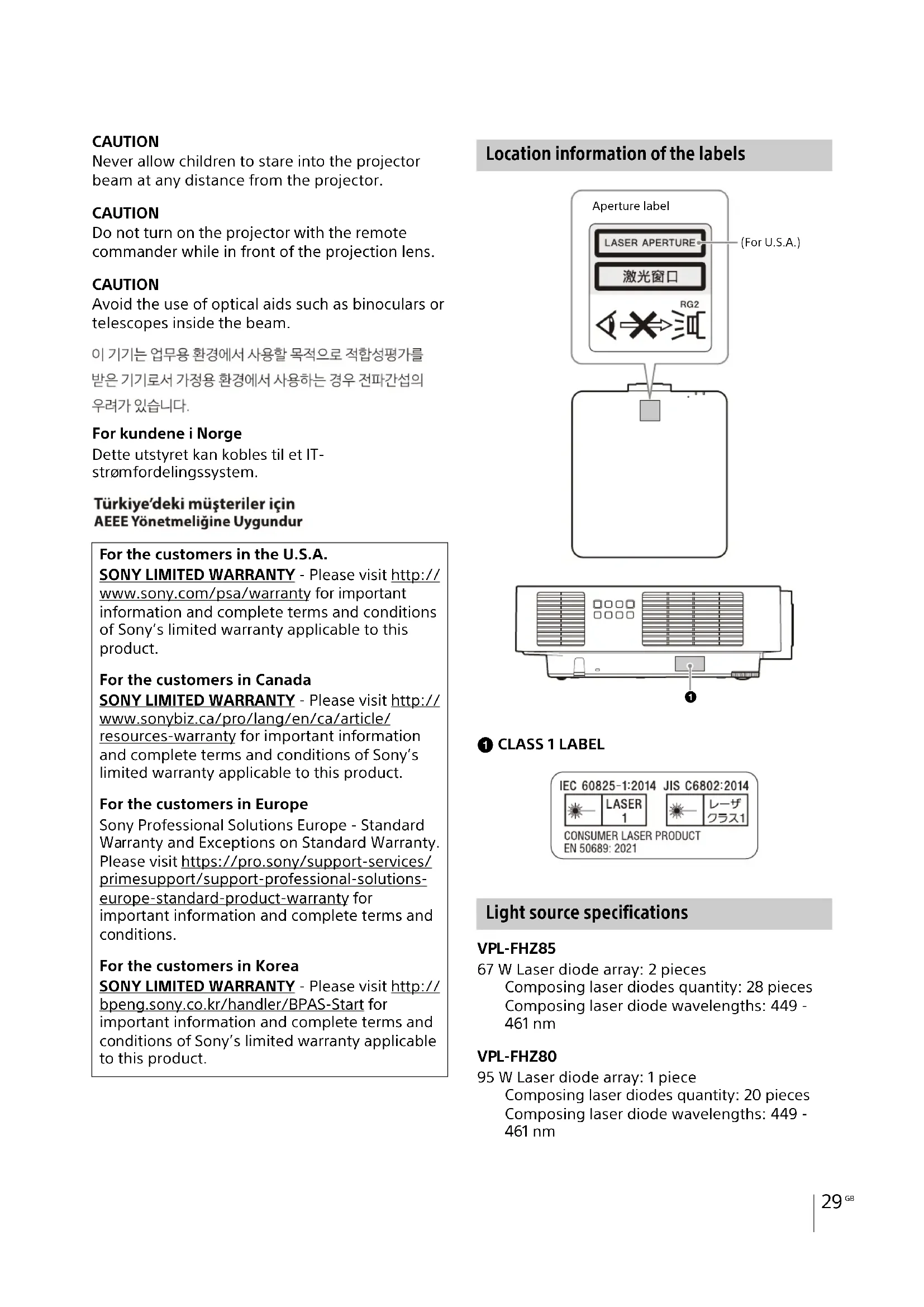
Location information of the labels

flowchart
graph TD
    A["Aperture label"] --> B["LASER APERTURE"]
    A --> C["激光窗口"]
    A --> D["RG2"]
    D --> E["Square icon"]
    style A fill:#f9f,stroke:#333
    note right of A (For U.S.A.)
    note right of A (For U.S.A.)
natural_image
Diagram of a front-mounted air conditioner unit with ventilation grilles and a control panel (no text or symbols)① CLASS 1 LABEL
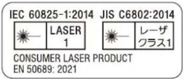
Light source specifications
VPL-FHZ85
67 W Laser diode array: 2 pieces Composing laser diodes quantity: 28 pieces Composing laser diode wavelengths: 449 - 461 nm
VPL-FHZ80
95 W Laser diode array: 1 piece Composing laser diodes quantity: 20 pieces Composing laser diode wavelengths: 449 - 461 nm
Beam divergence angle from lens of this unit
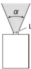
Laser emission port
| Lens Zoom maximum: α Zoom minimum: α | ||
| Standard lens 45° | 3° 29.4° | |
| VPLL-3007 84° | - | |
| VPLL-Z3009 69° | 61° | |
| VPLL-Z3010 61° | 46° | |
| VPLL-Z3024 28° | 21° | |
| VPLL-Z3032 21° | 14° | |
| VPLL-3003 122° | - | |
The distance L' between the front of the lens (center) and the front of the cabinet
Unit: mm (inches)
| Lens | L' |
| Standard lens | 22.5 ( ^7/_8 ) |
| VPLL-3007 | 73.7 ( 2^29/_32 ) |
| VPLL-Z3009 | 72.5 ( 2^27/_32 ) |
| VPLL-Z3010 | 81.3 ( 3^3/_16 ) |
| VPLL-Z3024 | 31.2 ( 1^7/_32 ) |
| VPLL-Z3032 | 31.2 ( 1^7/_32 ) |
| VPLL-3003 | 277.3 ( 10^29/_32 ) |
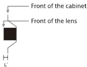
text_image
Front of the cabinet Front of the lensPrecautions
On safety
- Check that the operating voltage of your unit is identical with the voltage of your local power supply. If voltage adaptation is required, consult with qualified Sony personnel.
- Should any liquid or solid object fall into the cabinet, unplug the unit and have it checked by qualified Sony personnel before operating it further.
- Unplug the unit from the wall outlet if it is not to be used for several days.
- To disconnect the cord, pull it out by the plug. Never pull the cord itself.
- The wall outlet should be near the unit and easily accessible.
- The unit is not disconnected from the AC power source (mains) as long as it is connected to the wall outlet, even if the unit itself has been turned off.
- Do not look into the lens while in use.
- When turning on the projector, make sure no one is peeking at the projection lens.
- Do not let children use the unit alone.
- Do not place your hand or objects near the ventilation holes — the air coming out is hot.
- Be careful not to catch your fingers by the feet (adjustable) when you adjust the height of the unit. Do not push hard on the top of the unit with the adjuster out.
- Be sure to use two people to grasp both sides of the unit when carrying the unit.
- Avoid using an extension cord with a low voltage limited since it may cause the short-circuit and physical incidents.
- Do not catch your finger between the unit and surface of the floor when moving the projector installed on the floor.
- Be careful not to catch your finger in the cooling fan.
- Do not carry the projector with the cabinet on and with its cover open.
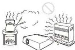
- Do not install the unit in a location near heat sources such as radiators or air ducts, or in a place subject to direct sunlight, excessive dust or humidity, mechanical vibration or shock.
- If a user disassembles, repairs, or alters the unit, it may cause a serious problem to the user's safety.
- If the projector malfunctions or is damaged, consult with a qualified Sony personnel.
- If the ventilation holes are blocked, internal heat builds up, and it may cause a fire or damage the unit. To allow adequate air circulation and prevent internal heat build-up, follow the items below:
- Place the unit, leaving sufficient space from walls or any objects (page 31).
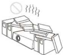
natural_image
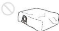
Line drawing of a mechanical device emitting smoke, with no text or symbols present.- Avoid using something to cover the ventilation holes (exhaust/intake).
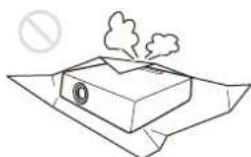
- Do not place the unit on surfaces such as an original packing sheet, soft cloth, papers, rugs, or scraps of paper. The ventilation holes may take in such materials.
natural_image
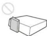
Simple line drawing of a smokestack on a surface with a prohibition symbol above (no text or labels)- Do not place any object in front of the lens that may block the light during projection. Heat from the light may damage the object. Use the blank function to cut off the picture.
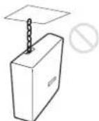
- Do not use the Security bar for the purpose of preventing theft for transporting or installing the unit. If you lift the unit by the Security bar or hang the unit by this bar, it may cause the unit to fall and be damaged, and may result in personal injury.
For dealers
- When the projector is mounted on the ceiling, a Sony bracket or recommended equivalent must be used for installation.
- Be sure to secure the cabinet cover firmly when installing to the ceiling firmly.
Safety precautions for installing the unit on a ceiling
- Never mount the projector on the ceiling or move it by yourself. Be sure to consult the store where you purchased the projector or a dedicated installer.
- When installing the unit on a ceiling, be sure to use a safety wire, etc., to prevent the unit from falling. For the installation, be sure to consult the store where you purchased the projector or a dedicated installer.
On Installation
- When installing the unit, leave space between any walls, etc. and the unit as illustrated.
Top view
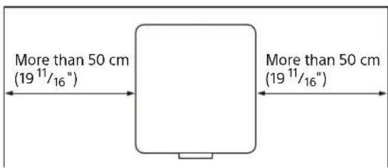
text_image
More than 50 cm (19 11/16") More than 50 cm (19 11/16")- Avoid using the unit in a location where the temperature or humidity is very high, or temperature is very low.
natural_image
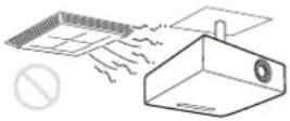
Illustration of a portable air conditioner unit emitting steam, with a chimney emitting smoke and a prohibition symbol above (no text or labels)- Avoid installing the unit in a location subject to direct cool or warm air from an air-conditioner. Installing in such a location may cause malfunction of the unit due to moisture condensation or rise in temperature.
- Avoid installing the unit in a location near a heat or smoke sensor. Installing in such a location may cause malfunction of the sensor.

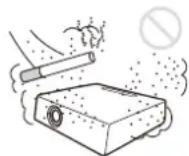
- Avoid installing the unit in a very dusty or extremely smoky environment. Otherwise, the air filter will become obstructed, and this may cause a malfunction of the unit or damage it.
- When using the unit in a location at an altitude of 1,000 m (approx. 3,280 feet) or higher, appropriately set "High Altitude Mode" in the "Installation" menu. Failing to do so could have adverse effects, such as reducing the reliability of certain components.
- Avoid installing the product in a space where space disinfectant components containing hypochlorous acid and chlorine dioxide are dispersed. Also, avoid spraying sanitizers or disinfectants near the product. This may cause discoloration of the product, deterioration of the material, failure due to corrosion, and easy clogging of the air filter.
On cleaning the lens and the cabinet
- Be sure to disconnect the AC power cord from the wall outlet before cleaning.
-
If you rub on the unit with a stained cloth, the cabinet may be scratched.
-
If the unit is exposed to volatile materials such as insecticide, or the unit is in contact with a rubber or vinyl resin product for a long period of time, the unit may deteriorate or the coating may come off.
- Do not touch the lens with bare hands.
- On cleaning the lens surface:
Wipe the lens gently with a soft cloth, such as a glass cleaning cloth. Stubborn stains may be removed with a soft cloth lightly dampened with water. Never use solvent such as alcohol, benzene or thinner, or acid, alkaline or abrasive detergent, or a chemical cleaning cloth. - On cleaning the cabinet:
Clean the cabinet gently with a soft cloth. Stubborn stains may be removed with a soft cloth lightly dampened with mild detergent solution and wrung, followed by wiping with a soft dry cloth. Do not use alcohol, benzine, thinner, sanitizers, or disinfectants.
On Illumination
To obtain the best picture, the front of the screen should not be exposed to direct lighting or sunlight.
On Heat Dissipation
The temperature of the projector cabinet may increase during or immediately after use; however, this is not a malfunction.
On Screen
When using a screen with an uneven surface, stripes pattern may rarely appear on the screen depending on the distance between the screen and the unit or the zooming magnifications. This is not a malfunction of the unit.
On Fan
Since the projector is equipped with a fan inside to prevent internal temperature from rising, there may be some noise. This is a normal result of the manufacturing process and does not indicate a malfunction. If, however, in a case of abnormal noise, consult with qualified Sony personnel.
About the Automatic Filter Cleaning Function
This unit has an automatic filter cleaning function. You may hear a filter tapping sound multiple times when the power is turned on or off, but this is not a malfunction.
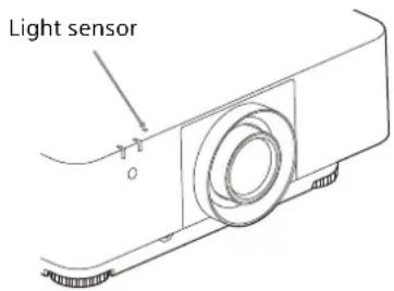
About the Light Sensor
This unit has a function that uses the light sensor to detect the brightness of the surroundings to perform automatic image quality correction.
text_image
Light sensorDo not block the light sensor when using automatic image quality correction based on the ambient brightness.
About Lens Replacement
When the power is connected, do not attach or remove the projection lens.
Do not attach any lens other than the specified accessory lens sold separately.
Do not replace the lens while the projector is mounted on the ceiling.
On inspection of light source related parts
Since the unit uses a laser, when adjusting or inspecting the light source related parts, particular attention and a safe environment are necessary. Be sure to consult with qualified Sony personnel.
On disposing used products
Do not dispose the used products and general garbage together.
Correctly dispose of used products to avoid harming the environment or the health of yourself and others. Follow the disposal regulations of your area.
LCD Projector
The LCD projector is manufactured using high-precision technology. You may, however, see tiny black points and/or bright points (red, blue, or green) that continuously appear on the LCD projector. This is a normal result of the manufacturing process and does not indicate a malfunction.
Also, when you use multiple LCD projectors to project onto a screen, even if they are of the same model, the color reproduction among projectors may vary, since color balance may be set differently from one projector to the next.
On condensation
If the room temperature where the projector is installed changes rapidly, or if the projector is moved suddenly from a cold to a warm place, condensation in the projector may occur. As the condensation may cause malfunction, be careful in adjusting temperature settings of the air conditioner. If condensation occurs, leave the projector turned on for about two hours before use.
Notes on security
- SONY WILL NOT BE LIABLE FOR DAMAGES OF ANY KIND RESULTING FROM A FAILURE TO IMPLEMENT PROPER SECURITY MEASURES ON TRANSMISSION DEVICES, UNAVOIDABLE DATA LEAKS RESULTING FROM TRANSMISSION SPECIFICATIONS, OR SECURITY PROBLEMS OF ANY KIND.
-
Depending on the operating environment, unauthorized third parties on the network may be able to access the unit. When connecting the unit to the network, be sure to confirm that the network is protected securely.
-
From a safety standpoint, when using the unit connected with the network, it is strongly recommended to access the Control window via a Web browser and change the access limitation settings from the factory preset values.
Also, it is recommended that you set a password with a sufficiently long character string that is hard to guess by others, and that you store it safely. - Do not browse any other website in the Web browser while making settings or after making settings. Since the login status remains in the Web browser, close the Web browser when you complete the settings to prevent unauthorized third parties from using the unit or harmful programs from running.
- When connecting this product to a network, connect via a system that provides a protection function, such as a router or firewall. If connected without such protection, security issues may occur.
Do not place this product close to medical devices
This product (including accessories) has magnet(s) which may interfere with pacemakers, programmable shunt valves for hydrocephalus treatment, or other medical devices. Do not place this product close to persons who use such medical devices. Consult your doctor before using this product if you use any such medical device.
Notes
- Always verify that the unit is operating properly before use. SONY WILL NOT BE LIABLE FOR DAMAGES OF ANY KIND INCLUDING, BUT NOT LIMITED TO, COMPENSATION OR REIMBURSEMENT ON ACCOUNT OF THE LOSS OF PRESENT OR PROSPECTIVE PROFITS DUE TO FAILURE OF THIS UNIT, EITHER DURING THE WARRANTY PERIOD OR AFTER EXPIRATION OF THE WARRANTY, OR FOR ANY OTHER REASON WHATSOEVER.
- SONY WILL NOT BE LIABLE FOR CLAIMS OF ANY KIND MADE BY USERS OF THIS UNIT OR MADE BY THIRD PARTIES.
- SONY WILL NOT BE LIABLE FOR THE TERMINATION OR DISCONTINUATION OF ANY SERVICES RELATED TO THIS UNIT THAT MAY RESULT DUE TO CIRCUMSTANCES OF ANY KIND.
License Notice
Refer to "Notice on the Software" in the Help Guide and read the contents of the license.
Step 1
Preparing
Checking the Supplied Accessories
Remote Commander (RM-PJ30) (1)
Size AA (R6) batteries (2)
AC power cord (1)
Plug holder (1)
Setup Guide (this manual) (1)
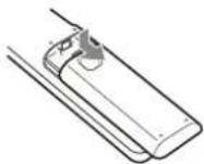
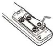
Installing batteries
1 Remove the lid, then install the two AA (R6) batteries (supplied) with the correct polarity.
While pressing the lid, slide it.
Be sure to install the battery from the ⊖ side.
2 Replace the lid.
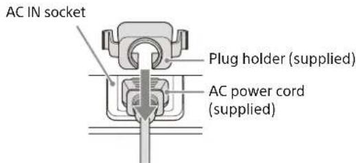
Connecting the AC Power Cord
1 Plug the AC power cord into the AC IN socket, then attach the plug holder to the AC power cord.
text_image
AC IN socket Plug holder (supplied) AC power cord (supplied)2 Slide the plug holder over the AC power cord to fix to the unit.
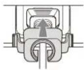
Step 2
Connecting
Notes
- Turn off all devices before making any connections.
- Use the proper cables for each connection.
- Insert the cable plugs firmly; Loose connections may reduce performance of picture signals or cause a malfunction. When unplugging a cable, be sure to grip the plug, not the cable itself.
- For more information, refer also to the instruction manual of the device to be connected.
- Use a no-resistance audio cable.
Connecting to a Computer
Connect the INPUT C terminal to a computer's HDMI output terminal.
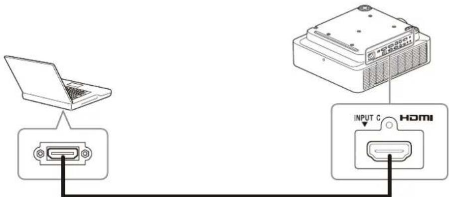
text_image
Diagram showing connection between a laptop and an HDMI device via USB port, with labeled ports and cable connections.HDMI cable (not supplied)
Notes
- Use an HDMI compatible device with the HDMI Logo.
- Use a high speed HDMI cable(s) on which the cable type logo is specified. (Sony products are recommended.)
- The HDMI terminal of this projector is not compatible with DSD (Direct Stream Digital) signal or CEC (Consumer Electronics Control) signal.
Using a LAN terminal
Connect the LAN terminal and the computer LAN terminal via a hub or router.
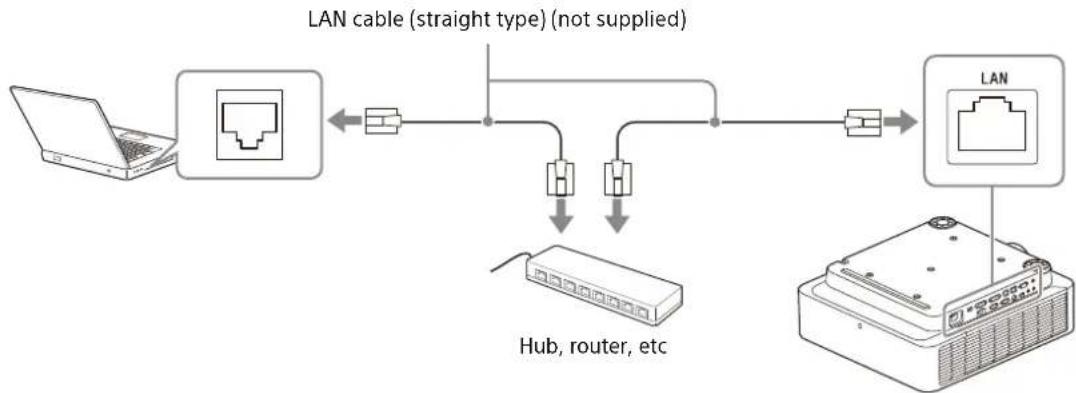
flowchart
graph TD
    A["Laptop"] --> B["Router"]
    B --> C["LAN cable (straight type) (not supplied)"]
    C --> D["Hub, router, etc"]
    D --> E["Server"]
    E --> F["LAN"]
Notes
- When using network features via the LAN terminal, be sure to check if "LAN Setting" is set to "LAN Port" under "HDBaseT Settings."
- Connect the projector to the network that is constructed to control the access from the internet, such as LAN. If the projector is connected directly to the internet, the security risk is increased.
When you monitor and control the projector via the network, access the Control Window of the projector (refer to "Using Network Features" in the Help Guide) via a Web browser and enable the desired control protocol.
Connecting to an HDBaseT™ Device
The HDBaseT transmitter is used when connecting the projector to a computer, video device, or network equipment.
Notes for connecting this unit to the HDBaseT transmitter
- Ask a professional or Sony dealer to perform wiring. If wiring has been insufficiently performed, it affects the transmission characteristics of the cable, and causes broken or unstable images.
- Connect the cable directly to the HDBaseT transmitter without going through a hub or router.
-
Use cables that meet the following conditions.
-
CAT5e or higher
- Shielded type (covering connectors)
- Straight wire connection
- Single wire
- When installing the cables, use a cable tester, cable analyzer, or similar device to check if the cables meet the CAT5e or higher requirement. If there is a transit connector between this unit and the HDBaseT transmitter, include it when measuring.
• To reduce the affect of noise, install and use the cable in a manner where it is not rolled up and it is as straight as possible.
• Install the cable away from the other cables (especially the power cable).
- When installing multiple cables, do not bind them and keep the running parallel distance as short as possible.
- The transmittable distance of the cable is 100 m (approx. 328 feet) maximum. If it exceeds 100 m (approx. 328 feet), it may cause broken images or a malfunction in LAN communication. Do not use the HDBaseT transmitter beyond the maximum transmittable distance of the cable.
- For operation or function problems caused by devices of other manufacturers, contact the relevant manufacturer.
Connecting to a computer/video device
Connect the HDBaseT terminal on the projector to the HDBaseT terminal on the HDBaseT transmitter, then connect the HDMI terminal on the HDBaseT transmitter to the HDMI output terminal on a computer or video device.
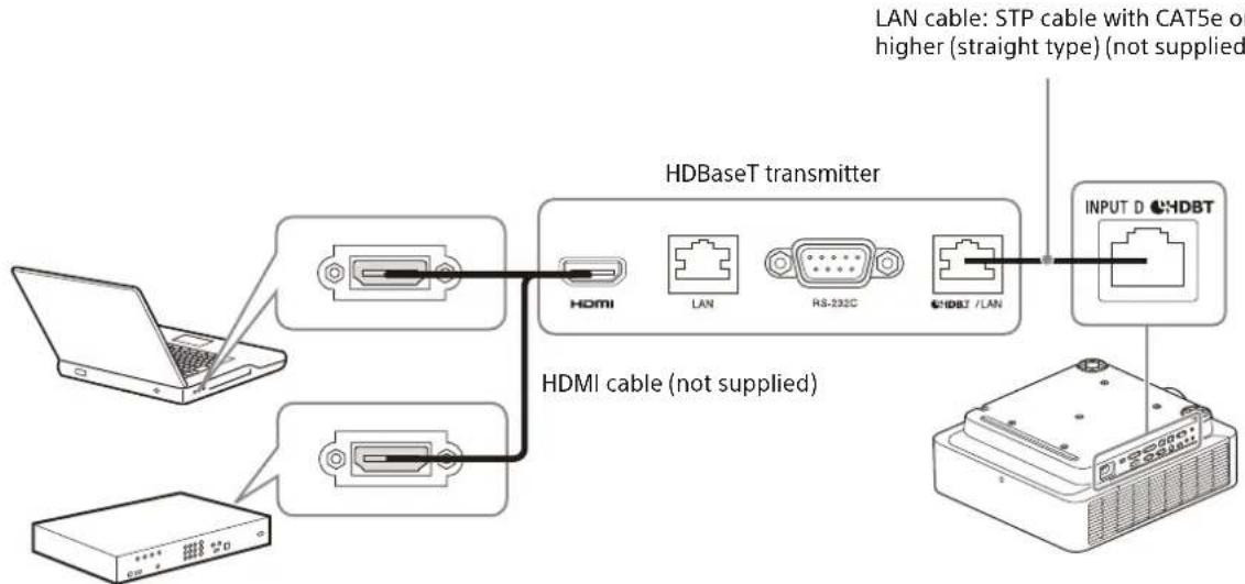
flowchart
graph TD
    A["Laptop"] --> B["HDBaseT transmitter"]
    C["Hardware"] --> D["HDMI cable (not supplied)"]
    B --> E["LAN"]
    B --> F["RS-232C"]
    B --> G["HDBAT / LAN"]
    G --> H["INPUT D CAT5e"]
    H --> I["Output"]
For information on other connecting methods, refer to "Connecting" in the Help Guide.
Turning the Projector On/Off
1 Plug the AC power cord into a wall outlet.
2 Turn on the projector.
Press the I/① key on the main unit or the I key on the Remote Commander.
Turning Off the Power
1 Press the I/⏻ key on the main unit or the ⏻ key on the Remote Commander.
The projector starts shutdown and turns off. For long-term use, turn off the projector when not in use.
2 Unplug the AC power cord from the wall outlet.
Selecting the Menu Language
The factory setting for the language for displaying menus, messages, etc. is English. To change the on-screen language, proceed as follows:
1 Plug the AC power cord into a wall outlet.
2 Turn on the projector.
Press the I/① key on the main unit or the I key on the Remote Commander.
3 Press the MENU key to display the menu screen.
If the display cannot be properly seen, adjust the focus, size, and position of the projected image (page 40).
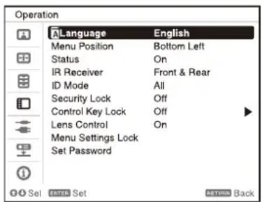
4 Select the menu language.
① Press the ↑ or ↓ key to select the Operation (☐ menu then press the ENTER key.
② Press the ↑ or ↓ key to select "Language (") then press the ENTER key.
text_image
Operation Language English Menu Position Bottom Left Status On IR Receiver Front & Rear ID Mode All Security Lock Off Control Key Lock Off Lens Control On Menu Settings Lock Set Password OK Set OK Back③ Press the /// key to select a language, then press the ENTER key.
5 Press the MENU key to turn off the menu screen.
Projecting an Image
The size of a projected image depends on the distance between the projector and screen. Place the projector so that the projected image fits the screen size. For details on projection distances and projected image sizes, see "Projection Distance" in the Help Guide.
1 Plug the AC power cord into a wall outlet.
2 Connect all necessary devices to the projector (page 36).
3 Turn on the projector.
Press the I/⏻ key on the main unit or the I key on the Remote Commander.
4 Turn on the connected device.
5 Select the input source.
Press the INPUT key on the projector or on the Remote Commander to display the input select window. Press the INPUT key repeatedly or the ♦/▼ key to select an image to be projected. The signal icon appears on the right side in the input select window when a signal is input. When there are multiple terminals to which signals are input, the terminals to which the signals are input are automatically selected each time the INPUT key is pressed.
You can select the input source using direct input select keys on the Remote Commander.
6 Change the computer screen output destination to an external display.
How to change the output destination varies, depending on the type of computer.
(Example)
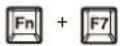
7 Adjust the focus, size and position of the projected image (page 40).
Adjusting the Projected Image
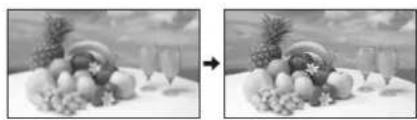
Focusing the image (Focus)
natural_image
Black-and-white photo showing a table with fruit and a decorative bowl, no visible text or symbolsWhen attaching the electric focus lens
Press the FOCUS key on the projector or the Remote Commander, then press the /// key to adjust the focus. Press the FOCUS key on the projector or the Remote Commander to display the focus adjustment pattern.
When attaching the manual focus lens
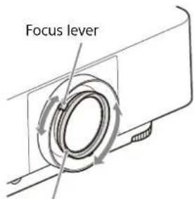
Turn the focus lever and peripheral focus ring to adjust the focus.
You can adjust the focus of the peripheral area by rotating the peripheral focus ring.
text_image
Focus leverPeripheral focus ring
Adjusting the image size (Zoom)
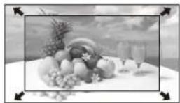
When attaching the electric zoom lens
Press the ZOOM key on the projector or the Remote Commander, then press the ♦/♦/♦/♦ key to adjust the size. Press the ZOOM key on the projector or the Remote Commander to display the zoom adjustment pattern.
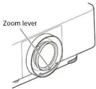
When attaching the manual zoom lens
Turn the zoom lever to adjust the size.
text_image
Zoom leverAdjusting the position of the image (Lens shift)
natural_image
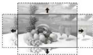
Black-and-white still life photo of fruits and grapes on a table, with arrows indicating direction (no text or symbols)Press the SHIFT key on the projector or the LENS SHIFT key on the Remote Commander, then press the /// key to adjust the position. Press the SHIFT key on the projector or the LENS SHIFT key on the Remote Commander to display the shift adjustment pattern.
To return the lens to the center position of the projected image
Press the RESET key on the Remote Commander while adjusting.
Note
Do not touch the lens when you adjust the image position. Your fingers may be pinched when the lens extends/retracts.
Adjusting the tilt of the projector with the front feet (adjustable)
If the projector is installed on an uneven surface, adjust the position of the projected image by changing the tilt of the projector with the front feet (adjustable).

natural_image
Diagram of a projector with a circular base and internal components, showing no text or symbols.Notes
- Be careful not to let the projector down on your fingers.
- Do not push hard on the top of the projector with the front feet (adjustable) extended. It may cause malfunction.
If you need to further adjust projected images, refer to "Adjusting" in the Help Guide.
Indicators
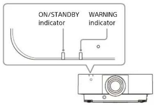
You can check the projector status or abnormality by checking the lighting/flashing status of the ON/STANDBY indicator and WARNING indicator on the front. If the indicators flash in red, address the problem in accordance with "Warning indication and remedies" (page 43).
text_image
ON/STANDBY indicator WARNING indicatorStatus indication
| Indicator status Operating status Description | |
(Li 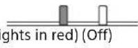 | Standby The power is supplied to the projector and the projector is in a standby mode according to the setting. |
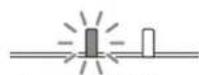 (Flashes in green) (Off) (Flashes in green) (Off) | Warm-up The projector is warming up after it is turned on. |
(Ligt 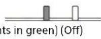 | Power on The projector is ready for projection. |
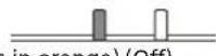 (Lights in orange) (Off) (Lights in orange) (Off) | Other standby status The projector is in With No Input (Light Cutoff). |
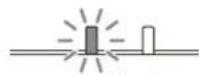 (Flashes in orange) (Off) (Flashes in orange) (Off) | Updating software The projector software is being updated. |
Warning indication and remedies
| Indicator status Number of flashes Meaning/Remedies | |
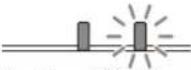 (Lights in red) (Flashes in red) (Lights in red) (Flashes in red) | Twice The side cover or air filter is not installed securely.Check how the side cover or air filter is attached and install it securely. |
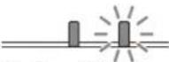 (Lights in red) (Flashes in red) (Lights in red) (Flashes in red) | Three times The light source does not light properly.Unplug the AC power cord and make sure the ON/STANDBY indicator turns off, then plug the AC power cord into the wall outlet and turn on the projector. |
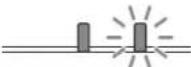 (Lights in red) (Flashes in red) (Lights in red) (Flashes in red) | Eight times The lens is not securely attached.Check how the lens is attached and install it securely. |
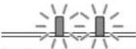 (Flashes in red) (Flashes in red)Both indicators flash (Flashes in red) (Flashes in red)Both indicators flash | Twice The temperature in the projector is abnormal.Perform the following.Check if the air filter is clogged, then clean or replace it (page 44).Check if the ventilation holes (intake/exhaust) are not blocked by the wall or an object and secure a sufficient gap.Check the ambient temperature and use the projector within the range of operating temperature. |
If the indicators flash in a manner other than described above, unplug the AC power cord and make sure the ON/STANDBY indicator turns off, then plug the AC power cord into the wall outlet and turn on the projector.
If the problem still persists, consult with qualified Sony personnel.
If there is any problem or an error message appears on the screen, refer to "Messages List" or "Troubleshooting" in the Help Guide.
Cleaning the Air Filter
When the message that prompts cleaning the air filter appears, clean the air filter.
If the dust cannot be removed from the air filter even after cleaning, replace the air filter with a new one.
For details on a new air filter, consult with qualified Sony personnel.
Caution
If you continue to use the projector even after the message is displayed, dust may accumulate, clogging it. As a result, the temperature may rise inside the unit, leading to a possible malfunction or fire.
1 Turn off the projector and disconnect the AC power cord from a wall outlet.
Note
If you remove the air filter while the power is turned on, you may accidentally touch the fan inside the unit, which may cause injury.
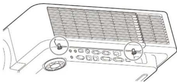
2 Loosen the two screws on the bottom of the side cover.
natural_image
Line drawing of a car air conditioner unit with control panel and two circular insets showing water flow (no text or symbols)3 Press down on the upper part of the side cover while sliding it downward to detach.
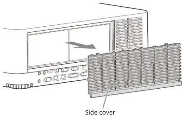
text_image
Side cover4 Pull out the air filter from the main unit.
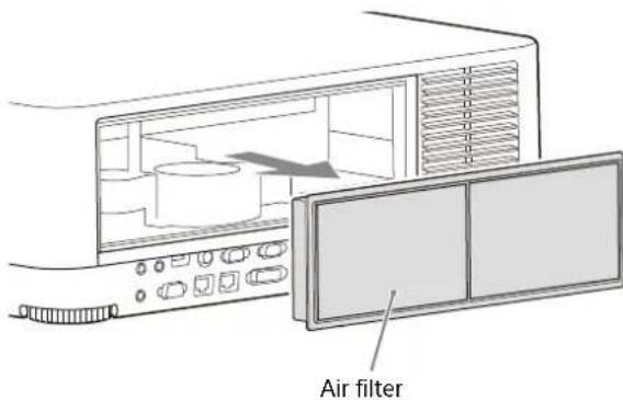
text_image
Air filter5 Clean the air filter with a vacuum cleaner.
6 Replace the air filter and attach the side cover to the unit.
Note
Be sure to attach the air filter firmly; the power cannot be turned on if it is not attached securely.
Replacing the Projection Lens
Notes
- Avoid removing/attaching the lens with the projector installed suspended from a ceiling.
- For usable projection lenses, see "Optional accessories" in the Help Guide.
- Do not attach any lens other than the specified accessory lens sold separately.
- Be careful not to drop the projection lens.
- Avoid touching the lens surface.
Removing
1 Return the projection lens to the center position.
While the unit is turned on, press the LENS SHIFT key on the Remote Commander, then press the RESET key on it. The projection lens returns to the center position.
Note
The projection lens cannot be removed unless it has returned to the center position.
2 Turn off the projector, then unplug the AC power cord from the wall outlet.
Caution
When replacing the lens, your eyes may be damaged if a strong light accidentally gets into your eyes. Before replacing the lens, turn off the projector and then unplug the AC power cord.
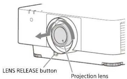
3 While pressing and holding down the LENS RELEASE button, rotate the projection lens counterclockwise to pull out the lens straight.
text_image
LENS RELEASE button Projection lensAttaching
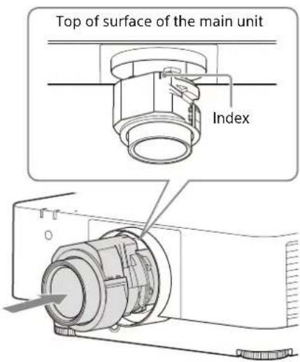
1 Fully insert the projection lens with the index on the lens facing toward the top surface of the main unit.
text_image
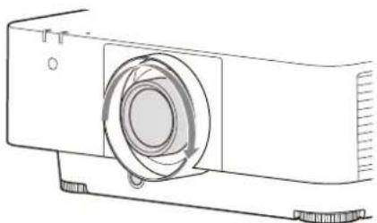
Top of surface of the main unit Index2 Rotate the lens clockwise until it clicks.
natural_image
Line drawing of a projector with a circular component and base mount (no text or symbols)Note
When attaching the projection lens, do not press the LENS RELEASE button.
Dimensions
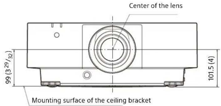
Front
text_image
Center of the lens 99 (3 29/32) Mounting surface of the ceiling bracket 101.5 (4)Unit: mm (inches)
Side
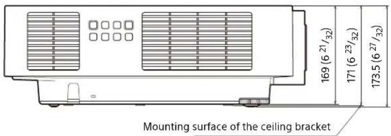
text_image
Mounting surface of the ceiling bracket 169 (6 21/32) 171 (6 23/32) 173.5 (6 27/32)Unit: mm (inches)
Top
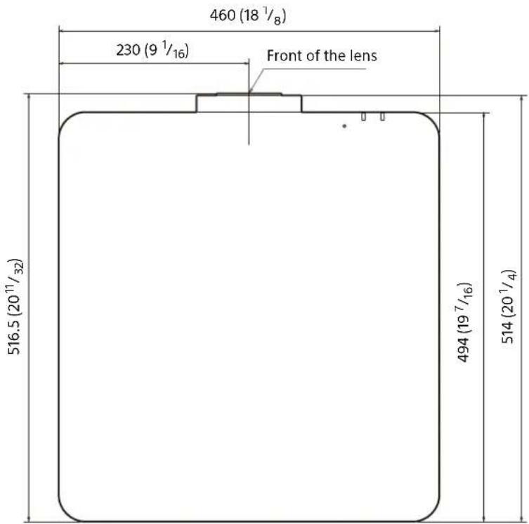
text_image
460 (18 1/8) 230 (9 1/16) Front of the lens 516.5 (20 11/32) 494 (19 7/16) 514 (20 1/4)Unit: mm (inches)
Bottom
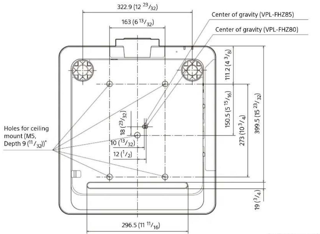
text_image
322.9 (12 23/32) 163 (6 13/32) Center of gravity (VPL-FHZ85) Center of gravity (VPL-FHZ80) Holes for ceiling mount (M5, Depth 9 (11/32))* 18 (23/32) 10 (13/32) 12 (1/2) 111.2 (4 3/8) 150.5 (5 15/16) 273 (10 3/4) 399.5 (15 23/32) 19 (3/4) 296.5 (11 11/16)Unit: mm (inches)
* Specifications of ceiling mount holes
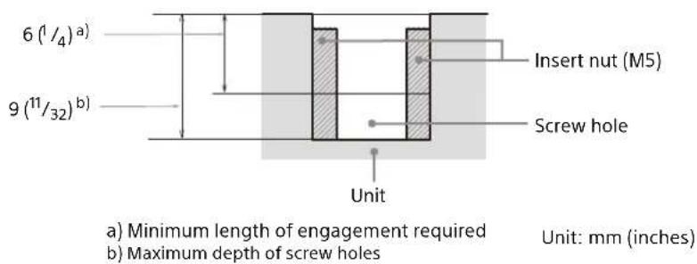
text_image
6 (1/4)a) 9 (11/32)b) Insert nut (M5) Screw hole Unit a) Minimum length of engagement required b) Maximum depth of screw holes Unit: mm (inches)- Be sure to use screws that are longer than the minimum length of engagement and shorter than the maximum depth of screw holes as shown in the figure above.
- Recommended tightening torque: 1.4 ± 0.2 ~N · m
Raccordement Page 58
Étape 3
Projection...... Page 61
Témoins Page 64
natural_image
Simple line drawing of a trash bin with smoke and a prohibition symbol above (no text or labels)natural_image
Simple line drawing of a smokestack emitting smoke from a tray, with no text or symbols present.natural_image
Illustration of a steam stove emitting smoke next to a portable heater and a heater with cooling effect (no text or symbols)text_image
Diagram showing connection between a laptop and an HDMI device via USB port, with labeled input/output ports.text_image
Operation Language English Menu Position Bottom Left Status On IR Receiver Front & Rear ID Mode All Security Lock Off Control Key Lock Off Lens Control On Menu Settings Lock Set Password OK Select Next Set Next Backnatural_image
Two grayscale photos showing a fruit arrangement on a table, one with a rainbow and the other with a bowl of fruit (no text or symbols)natural_image
Black-and-white photo of a basket of fruits and vegetables on a surface, with arrows pointing to the sky (no text or symbols)natural_image
Diagram of a projector with a circular base and internal components, showing no text or symbols.Remarques
natural_image
Line drawing of a car air conditioner unit with control panel and two circular insets showing internal components (no text or symbols)natural_image
Line drawing of a projector with a circular lens and base mount (no text or symbols)Remarque
natural_image
Diagram of a front-mounted air conditioner unit with ventilation grilles and a control panel (no text or symbols)① ETIQUETA DE CLASE 1
natural_image
Line drawing of a cluttered device emitting smoke or vapor (no text or symbols)natural_image
Simple line drawing of a smokestack on a surface with a prohibition symbol above (no text or labels)natural_image
Illustration of a steam rising from a chimney to a computer with smoke, no text or symbols presenttext_image
Diagram showing connection between a laptop and an HDMI device via USB port, with labeled input/output ports.text_image
Operation Language English Menu Position Bottom Left Status On IR Receiver Front & Rear ID Mode All Security Lock Off Control Key Lock Off Lens Control On Menu Settings Lock Set Password OK Select Next Set Next Backnatural_image
Diagram of a projector with a circular base and internal components, showing no text or symbols.Notas
natural_image
Line drawing of a car air conditioner panel with control buttons and fan (no text or symbols)natural_image
Line drawing of a projector with a circular vent and base mount (no text or symbols)Nota
natural_image
Diagram of a front-mounted air conditioner unit with ventilation grilles and a control panel (no text or symbols)① AUFKLEBER MIT DEM HINWEIS ZUR KLASSE 1
natural_image
Line drawing of a cluttered machine with smoke and a prohibition symbol above (no text or labels)natural_image
Simple line drawing of a building on a roof with smoke and a prohibition symbol (no text or labels)natural_image
Illustration of a portable stove with steam rising, next to a toaster and a chimney emitting smoke (no text or symbols)natural_image
Mechanical assembly diagram showing a clamping mechanism with no visible text or symbolstext_image
Diagram showing connection between a laptop and an HDMI device via USB port, with labeled input/output ports.text_image
Operation Language English Menu Position Bottom Left Status On IR Receiver Front & Rear ID Mode All Security Lock Off Control Key Lock Off Lens Control On Menu Settings Lock Set Password OK Set Backnatural_image
Two grayscale photos showing a table with fruit and vegetables, one rotated to show a change (no text or symbols)natural_image
Black-and-white photo of a basket of fruits and vegetables on a surface, with arrows pointing to the sides (no text or symbols)natural_image
Diagram of a projector with a circular base and internal components, showing no text or symbols.Hinweise
natural_image
Line drawing of a car air conditioner unit with control panel and fan (no text or symbols)natural_image
Line drawing of a projector with a circular lens and base mount (no text or symbols)Hinweis
natural_image
Diagram of a front-mounted air conditioner unit with ventilation grilles and a control panel (no text or symbols)① ETICHETTA CLASSE 1