TD 1500 - Turntable THORENS - Free user manual and instructions
Find the device manual for free TD 1500 THORENS in PDF.
| Product Type | Turntable |
| Brand | Thorens |
| Model | TD 1500 |
| Drive Type | Belt |
| Motor | DC |
| Speeds | 33 1/3 and 45 rpm |
| Speed Fluctuation | 0.08% DIN / WRMS |
| Platter | Die-cast aluminum, diameter 300 mm |
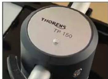
| Tonearm | Thorens TP150, J-shape, statically balanced |
| Effective Tonearm Length | 232.8 mm |
| Effective Tonearm Mass | 15 g |
| Maximum Tracking Weight | 30 g |
| Overhang | 17.8 mm |
| Included Cartridge | Ortofon 2M Bronze (MM) |
| Stylus Profile | Nude Fidelity Line |
| Frequency Range | 20 Hz - 29 kHz |
| Output Voltage | 5.5 mV (1 kHz, 3.54 cm/s) |
| Recommended Tracking Force | 1.5 g ±0.2 g |
| Cartridge Weight | 7.2 g |
| Headshell Weight | 13.5 g |
| Outputs | RCA/Cinch (gold) and XLR |
| Power Supply | AC 100-240 V, 50/60 Hz, 6 W |
| Dimensions (W x D x H) | 440 x 370 x 180 mm |
| Warranty | Legal warranty on the drive system, tonearm and motor |
| Maintenance | Regular cleaning of records and stylus; replace stylus every 500 hours of use |
Frequently Asked Questions - TD 1500 THORENS
User questions about TD 1500 THORENS
0 question about this device. Answer the ones you know or ask your own.
Ask a new question about this device
Download the instructions for your Turntable in PDF format for free! Find your manual TD 1500 - THORENS and take your electronic device back in hand. On this page are published all the documents necessary for the use of your device. TD 1500 by THORENS.
USER MANUAL TD 1500 THORENS
PYKOBODCTBO NOJb3OBATEJIY
使用手册
Thorens GmbH
Weiss = Signal links
Blau = Masse links
PYKOBODCTBO NOLBJ3OBATEJI
使用手册
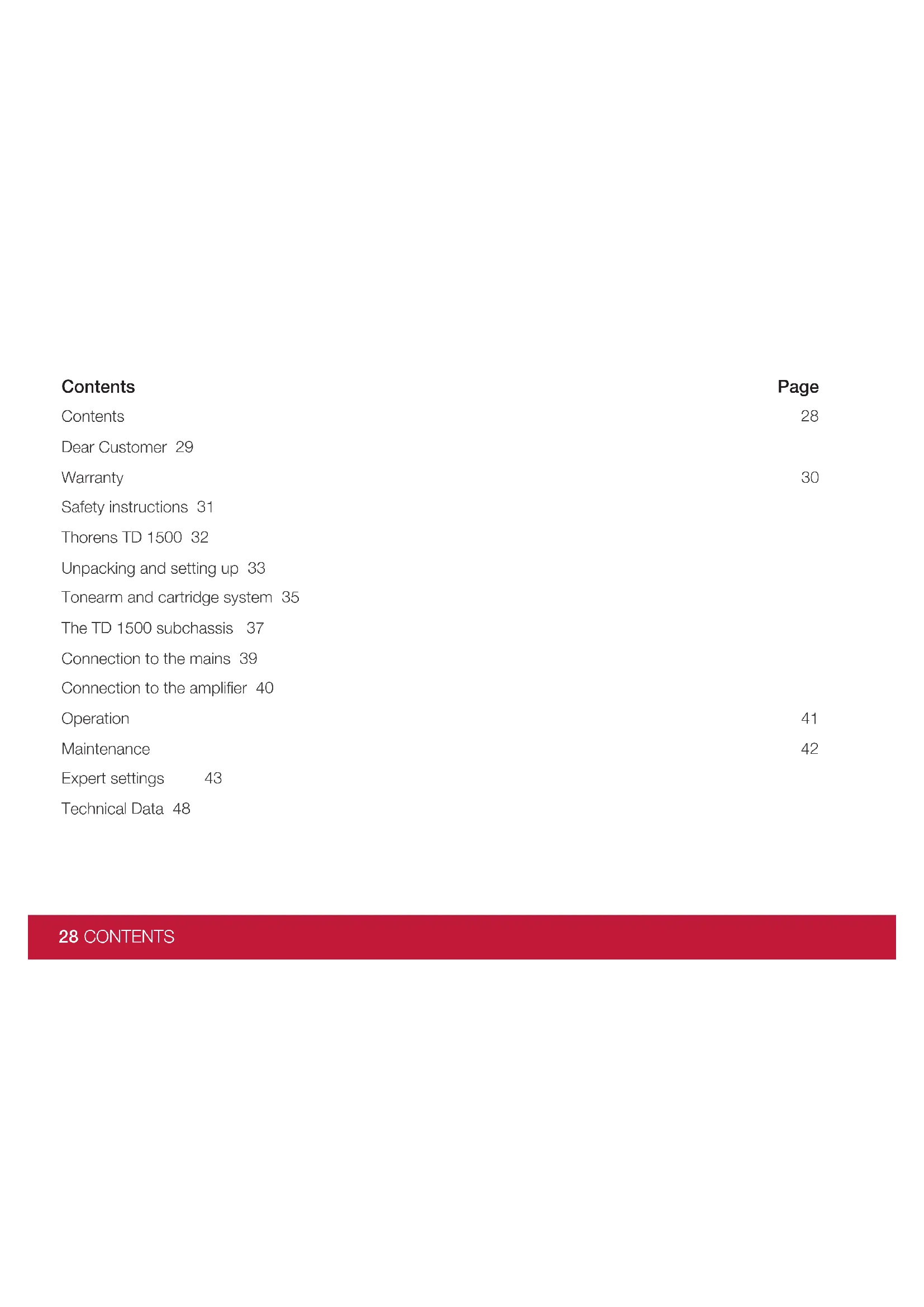
| Contents | Page |
| Contents | 28 |
| Dear Customer 29 | |
| Warranty | 30 |
| Safety instructions 31 | |
| Thorens TD 1500 32 | |
| Unpacking and setting up 33 | |
| Tonearm and cartridge system 35 | |
| The TD 1500 subchassis 37 | |
| Connection to the mains 39 | |
| Connection to the amplifier 40 | |
| Operation | 41 |
| Maintenance | 42 |
| Expert settings 43 | |
| Technical Data 48 |
28 CONTENTS
Dear Customer,
We are very pleased with the confidence you have shown in us by purchasing the Thorens TD1500 precision turntable.
In this document we describe in detail how to set up the unit so that you can enjoy your valuable records for many years. Please read this manual carefully before using the unit and do not hesitate to contact your authorised Thorens dealer if you have any further questions.
With musical regards,
Your Thorens Team
Warranty
Statutory warranty and guarantee regulations apply without restriction. In case of a defect
during this period, please contact your Thorens dealer and discuss the further procedure with him. In the event of transport or shipment, please ensure that the sensitive device is securely packaged and preferably use the original packaging. If this is no longer available, your dealer will provide you with replacement packaging.
The Thorens warranty covers the turntable, tonearm, motor including control electronics and power supply. Cartridges are the responsibility of the respective manufacturer.
If a defect is due to misuse or transport damage, this damage is not covered by the Thorens warranty. In case of doubt, always contact your local dealer.
WARNING!
Never operate the unit in a damp environment or in the rain.
Before switching on, make sure that all electrical connections have been made safely and that the voltage at the power supply unit corresponds to the local mains voltage.
Safety instructions
To reduce risk of electric shock, do not remove the cover (or back). No user-serviceable parts inside.
WARNING
TO PREVENT FIRE OR SHOCK HAZARD, DO NOT EXPOSE THIS APPLIANCE TO RAIN OR MOISTURE.

EXPLANATION OF GRAPHICAL SYMBOLS
The lightning flash with arrowhead symbol, within an equilateral triangle, is intended to alert you to the presence of uninsulated 'dangerous voltage' within the product's enclosure that may be of sufficient magnitude to constitute an electric shock to persons.
The exclamation point within an equilateral triangle is intended to alert you to the presence of important operating and maintenance (servicing) instructions in the literature accompanying the appliance.

This product was tested and complies with all the requirements for the CE Mark.
Compliant to 2002/95/EC (RoHS)
IMPORTANT: DISPOSAL OF WASTE EQUIPMENT BY USERS IN PRIVATE HOUSEHOLDS IN THE EUROPEAN UNION
This symbol on the product or on its packaging indicates that this product must not be disposed off with your other household waste. Instead, it is your responsibility to dispose of your waste equipment by handing it over to a designated collection point for the recycling of waste electrical and electronic equipment. The separate collection and recycling of your waste equipment at the time of disposal will help to conserve natural resources and ensure that it is recycled in a manner that protects human health and the environment. For more information about where you can drop off your waste equipment for recycling, please contact your local city office, your household waste disposal service or the shop where you purchased the product.
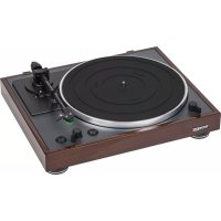
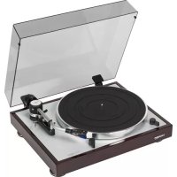
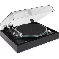
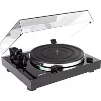
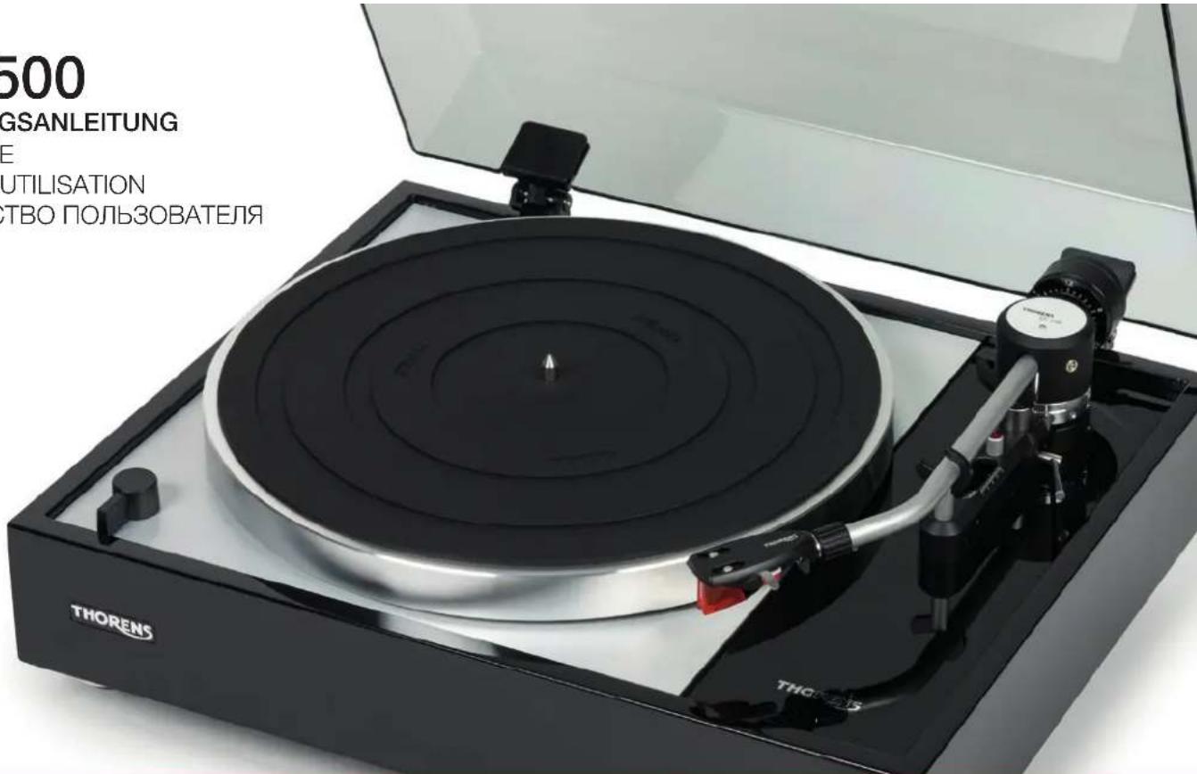
Thorens TD 1500
The Thorens TD 1500 is the reinterpretation of the legendary 1965 Thorens TD 150 with 21st century technology. A classic suspended sub-chassis on three adjustable conical springs, combined with the precise TP 150 tonearm and an electronically controlled DC motor, brings the traditional Thorens belt drive into our time. This leaves room for many years of musical enjoyment.
Unpacking and setting up
Carefully remove the record player and accessories from the packaging.
Warning: various accessories, such as the external power supply and the dust cover hinges, are inserted in their own areas of the polystyrene inserts.
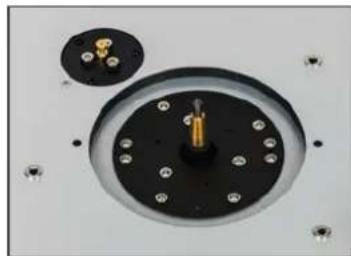
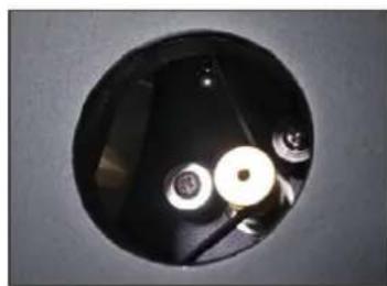
Place the turntable on a level surface and remove the two transport securing screws on the top board to the right and left of the platter axle (Fig. 1). They fix the sub-chassis and prevent it from swinging uncontrollably and possibly being damaged during transport.
Place the drive belt around the inner platter (Fig 2), place the platter on the centre axle and then place the belt through one of the two large holes in the platter around the drive pulley of the motor to the left of the centre axle (Fig 3).
This completes the installation of the drive.
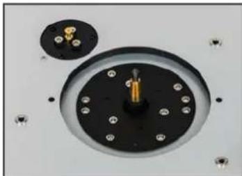
Fig. 1
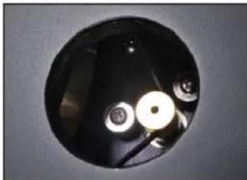
Fig. 3

Fig. 2
The TD 1500 can be operated with or without the dust cover. If you do not wish to use the cover, skip the following section.
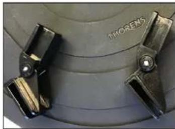
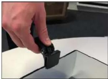
Carefully unpack the dust cover, lay it flat on top and slide the two hinges (Fig. 4) with the open side over the recesses on the back of the cover (Fig. 5).
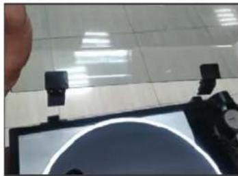
Then carefully slide the dust cover with the hinges into the receptacles at the back of the frame of the TD 1500 (Fig. 6).

Fig. 4

Fig. 5

Fig. 6
Tonearm and cartridge system
For the correct operation of the TD 1500, a few adjustments have to be made to the tonearm. The supplied Ortofon 2M Bronze cartridge is pre-installed and does not need to be adjusted. First, the counterweight is installed and then the tracking force and anti-skating are adjusted.
The counterweight of the tonearm has been packed separately for transport. For the correct adjustment of all necessary values, please follow the steps listed below:
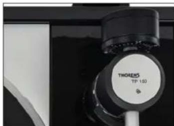
- Screw the counterweight onto the back of the end of the tonearm (picture 7).
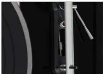
- Slide the anti-skating adjustment weight (picture 8) in the arm base as far back as possible towards the tonearm bearing.
- Fold the lift lever forward so that the lift bench is lowered.
- Remove the needle guard on the pick-up and loosen the tonearm lock.
- Carefully move the tone arm towards the turntable with the finger lever so that it can swing freely up and down. Make sure that the needle does not touch the platter or the chassis.
- Turn the counterweight until the tone arm floats freely and swings back into a straight line by itself. If the arm is up, turn the counterweight slightly counterclockwise, if it is down, turn it in the opposite direction until it is balanced.
- Put the tone arm back on the support and fix it.
- On the counterweight there is a ring with a scale for the tracking force in Pond, which can be moved independently of the weight. Now turn this ring alone, without turning the whole weight, until the 0 at the top is opposite the mark on the bearing block of the tone arm.
-
To set the desired tracking force, now turn the counterweight as a whole until the corresponding number is at the top. The Ortofon 2M Bronze cartridge supplied requires between 1.4 and 1.7 pounds of tracking force. Recommendation 1.5 pond.
-
Then move the weight for the anti-skating in the slot between the tonearm base at the back and the arm support at the front to the same value. On the scale, the long lines, seen from behind, indicate an increase of 0.5. To adjust the value, it is best to use a small screwdriver or the pin supplied with the tone arm height adjustment.
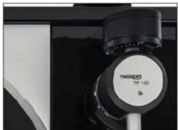
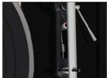
Fig. 7 Fig. 8
Important: the basic position at the base of the arm specifies the value 0.5, i.e. the other values are based on this.
Please carry out all these steps very carefully so as not to damage the delicate needle!
The TD 1500 subchassis
The Thorens TD 1500 has an invisible suspended sub-chassis to neutralise mechanical disturbances caused by vibrations of the sub-floor and resonances generated by the motor. This sub-chassis hangs from three conical springs adjustable from above below the topboard. This specially shaped sub-chassis is made of resonance damping Alucobond and supports both the turntable and the arm board with the mounted Thorens TP 150 tonearm. To prevent the sub-chassis from rocking, the cone springs also contain a damping element, like a shock absorber in a car.
This ensures that all moving parts are isolated from the rigid elements and the motor.
The sub-chassis is tuned by changing the spring tension by twisting it relative to the fixed parts of the drive. On the one hand, so that it vibrates evenly in a purely vertical direction and, on the other hand, so that the top board and tonearm board form a plane without any difference in height. It is also important to ensure that there is an even gap between the tone arm board and the frame to ensure that the springs do not give the sub-chassis a twist.
The correct adjustment of the sub-chassis is already done at the factory. However, you should check the vibration behavior after using the TD 1500 for some time and retighten the springs if necessary. Details on this can be found below in the chapter Expert Settings.
Installation
Although the Thorens TD 1500 is insulated from vibrations by its sub-chassis, you should still follow a few rules to achieve trouble-free operation with the best sound quality over years of use. In contrast to heavy mass-produced turntables, which must be placed on as solid a base as possible, turntables with sub-chassis such as the Thorens TD 1500 require a lighter but very stable base. This could be a small table or a light chest of drawers. These are exactly the conditions for the sub-chassis, which is tuned to a certain frequency, to work perfectly. Weight is less important than stability and torsional rigidity.
In addition, a set-up in the balance is important. A spirit level can serve as a check.
Connection to the mains
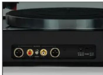
The Thorens TD 1500 is supplied with a 12V plug-in power supply unit that provides the electrical voltage required for operation. The connector for the appropriate plug of the power supply is located on the back of the turntable next to the power switch (Fig. 9). Please ensure that the plug is firmly seated in the socket.

Fig. 9
CONNECTION TO THE AMPLIFIER
There are two pairs of sockets on the rear panel for connecting the TD 1500 to an amplifier.
One pair of RCA sockets for a normal unbalanced connection to a phono amplifier and one pair of XLR outputs that allow the signal to be output balanced when using an MC cartridge. In the latter case, the phono preamplifier used should also allow balanced signal processing.
Parallel operation of the two pairs of outputs is not intended and may damage the equipment used.
Operation
The Thorens TD 1500 is a purely manual record player with no automatic functions and no limit stop.
-
place a record on the platter.
-
To start the motor, move the front left switch (fig. 10) from the centre position to the left or right, depending on the desired speed. The platter starts to rotate immediately, and your record can be played. For small 45 singles you need the single puck supplied.
-
Unlock the tone arm and make sure the lift is up (picture 11).
-
Move the tone arm over the record with your hand so that the needle hovers over the desired position and lower it with the lift (picture 12).
-
Playback begins.
-
When playback is finished, raise the arm with the lift and move it back to the support.
-
To switch off the drive, turn the switch back to ,0^ . The motor stops and the plate remains stationary.
-
if not in use for a longer period, switch off the power supply at the back with the switch and place the needle guard on the pick-up.
The drive electronics allow the speed to be switched directly without stopping the platter first.
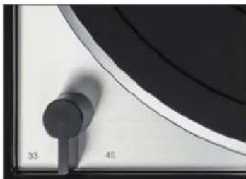
Fig. 11
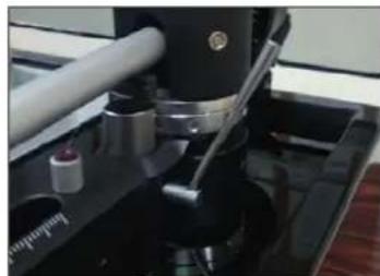
Fig. 12
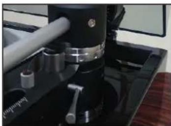
Fig. 13
MAINTENANCE
REPLACING THE STYLUS
The following applies to the Ortofon 2M Bronze cartridge supplied and the other models in the 2M series.
- Put on the needle guard, loosen the headshell cap nut and pull it off the tonearm tube.
- Remove the needle guard again and pull the needle carrier off to the front.
- Slide the new needle carrier onto the system body.
- Replace the needle guard and fix the headshell to the tonearm again.
- It is not necessary to change the settings on the tone arm if it is a replacement needle of the same type.
The needle should be checked after approx. 500 hours of operation and replaced if necessary.
If you are unsure about this, leave the replacement of the pick-up to your dealer or another competent person.
IMPORTANT RECOMMENDATION
Clean your valuable records regularly with a commercially available antistatic brush or use a record washing machine. Make sure that the scanning diamond is clean, using the small brush supplied to carefully sweep the diamond from back to front.
TRANSPORT OF THE TURNTABLE
It is best to use the original packaging of the unit for transport.
Put on the needle guard and lock the tone arm in its support. For longer transport or for shipping, loosen headshell and pull it off. Then remove the rear counterweight and set the anti-skating value to zero. Then remove the turntable and stow it on the bottom of the box.
Lift the dust cover off its hinges and pack it securely.
EXPERT SETTINGS
REPLACING THE CARTRIDGE
To replace the complete cartridge with another model, please follow the steps below.
- Put on the needle guard, unscrew the headshell and pull it off the tone arm tube.
- Pull off the four colored cables from the pins on the cartridge and unscrew it.
- Screw the new pick-up into the headshell and connect the cables. Do not tighten the screws yet.
- Move the pick-up in the headshell until the overhang and zero crossings fit. You will need an adjustment template for this.
- Tighten the screws.
Wiring diagram of the colored cables:
Red = signal right
Green = ground right
White = signal left
Blue = ground left
If you replace the complete catridge, the tone arm must be readjusted as described above.
CARTRIDGES WITH DIFFERENT INHERENT WEIGHTS
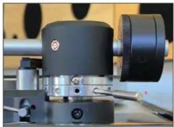
The counterweight of the TP150 tonearm is made of two parts in order to balance cartridges with different weights. The two parts are connected with two screws that can be easily loosened (Fig 13). However, it is advisable to adjust the weight so that it is as close as possible to the bearing of the tone arm in order to minimize the leverage effect on the arm. Therefore, always check first whether the arm can be balanced with the two weights connected. If this is not possible, unscrew the rear part of the weight.
If both weights are in combination, pickups up to approx. 30g own weight can be balanced.
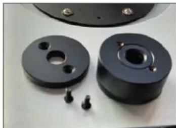
Fig. 13
ADJUSTMENT OF THE AZIMUTH
The azimuth is the correct vertical angle of the diamond needle into the grooves of the record, i.e. seen from the front, the diamond must be exactly perpendicular to the record.
The easiest way to check this is to use a mirror onto which the pick-up head is lowered. The pick-up system and the image must form a line without any kinks.
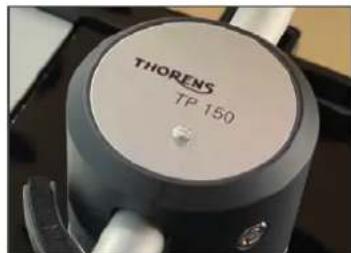
Fig. 14 Fig. 15

Alternatively, it is advisable to use a transparent stencil with a line grid, through which a slanted position of headshell and pick-up becomes directly visible. You may also be able to use a commercially available set square for this purpose.
To correct a possible deviation from the correct position, the tone arm can be turned.
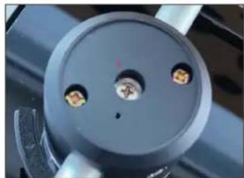
To do this, loosen the cover of the arm base (Fig 14) with a small flat-blade screwdriver and then slightly loosen the cross-head screw (Fig 15) (1) located centrally underneath.
CAUTION: please only loosen slightly, never unscrew!
After loosening the screw, the arm tube can be turned a few degrees in both directions. When doing so, always check the current position with a mirror or template.
Make sure never to move the arm lengthwise, but only sideways.
ADJUSTMENT OF THE TONE ARM HEIGHT
Replacing a pick-up may require a correction of the arm height. As a rule of thumb, when playing a record from the side, the arm should be parallel to the surface of the record. If this is not the case, because the new cartridge is either higher or lower, the arm height must be adjusted accordingly (Fig 16).
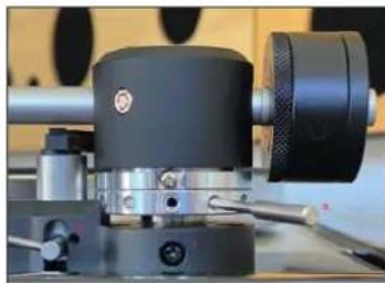
Fig. 16
A normal Phillips screwdriver (Ph2) and the
metal pin supplied are needed for this. For checking purposes, a triangle or a transparent template with parallel lines printed on it are suitable.
First, carefully loosen the screw (1) a little. Then use the pin (2) to turn the ring in the necessary direction until the tone arm has reached the desired height. Then tighten the screw (1) again.
In some cases, the lift may also need to be adjusted afterwards because the arm sits on the lift bench even when it is lowered or cannot be raised far enough. After loosening the screw (3), the lift height can be adjusted.
ADJUSTMENT OF THE SPRING TENSION
The sub-chassis should be evenly aligned and vibrate absolutely vertically. Neither wobble nor differ in height. To check and correct this, proceed as follows. 1:
-
push the turntable slightly downwards at the centre axis. This stimulates the sub-chassis and it should vibrate evenly.
-
Check the height of the tone arm board and the top board. Both should be exactly the same height, no jump in height when you run a finger over them.
-
Check the distance between the lower edge of the plate and the topboard. This distance should be the same around the entire circumference of the plate.
-
If both the height and the vibration behaviour are as described, everything is in order.
-
If, on the other hand, the sub-chassis wobbles and swings or the plate is not parallel to the topboard, the spring tension must be corrected.
-
Take the rubber mat off the turntable and turn it until you can see the three adjustment screws for the springs through the large holes. These are located in a triangular arrangement below the platter but can be reached through the holes in the platter (Fig. 17, Fig. 18).
-
Now adjust the spring tension of the three conical springs with a 2.5mm Allen key that fits into the groove of the nut visible through the plate. Turning clockwise increases the tension, lowering the sub-chassis at this point, turning the other way releases the tension, raising the sub-chassis at this point. Always check the vibration behavior in between.
-
The correct setting is achieved when the sub-chassis moves exactly vertically and the distance between platter and the top board is the same everywhere.

Fig. 17 Fig. 18

| Technical Data | |
| Drive Belt | |
| Motor DC Motor | |
| Speeds 33 1/3 and 45 rpm | |
| Wow & flutter 0,08 % DIN / WRMS | |
| Platter Aluminum Die-cast | |
| Diameter of Platter 12", 300mm | |
| Tonearm Thorens TP150 | |
| Type Static Balance, J-shaped | |
| Effective Length 9" / 232.8 mm | |
| Effective Mass 15 g | |
| Cartridge weight Max 30 g | |
| Overhang 17.8 mm | |
| Anti-skating Adjustment Counterweight guided with thread through ruby bearing | |
| Cartridge | |
| Type Ortofon 2M Bronze, MM | |
| Stylus Construction | Fine Line, nude |
| Frequency Response | 20Hz - 29kHz |
| Channel Separation | >26dB / 1kHz |
| Channel Balance | 1 dB / 1kHz |
| Vertical Tracking Angle | 20° |
| Supported Load Impedance | 47k Ohm |
| Output Voltage | 5.5mV (1kHz, 3.54cm/sec.) |
| Tracking Force 1.5g +/-0.2g | |
Technical Data
Cartridge Weight 7,2g
Headshell Weight 13.5g
Analog Output
Connector RCA/Cinch XLR
Power AC 100 - 240V, 50/60Hz
Power Consumption 6 W
Overall Dimensions (W x D x H) 440 x 370x 180mm
TD 1500
Chere cliente, Cher client 52
Garantie
53
Chere cliente, Cher client,
To reduce risk of electric shock, do not remove the cover (or back). No user-serviceable parts inside.
WARNING
TO PREVENT FIRE OR SHOCK HAZARD, DO NOT EXPOSE THIS APPLIANCE TO RAIN OR MOISTURE.


EXPLANATION OF GRAPHICAL SYMBOLS
The lightning flash with arrowhead symbol, within an equilateral triangle, is intended to alert you to the presence of uninsulated 'dangerous voltage' within the product's enclosure that may be of sufficient magnitude to constitute an electric shock to persons.
The exclamation point within an equilateral triangle is intended to alert you to the presence of important operating and maintenance (servicing) instructions in the literature accompanying the appliance.

This product was tested and complies with all the requirements for the CE Mark.
Compliant to 2002/95/EC (RoHS)

IMPORTANT: DISPOSAL OF WASTE EQUIPMENT BY USERS IN PRIVATE HOUSEHOLDS IN THE EUROPEAN UNION
This symbol on the product or on its packaging indicates that this product must not be disposed off with your other household waste. Instead, it is your responsibility to dispose of your waste equipment by handing it over to a designated collection point for the recycling of waste electrical and electronic equipment. The separate collection and recycling of your waste equipment at the time of disposal will help to conserve natural resources and ensure that it is recycled in a manner that protects human health and the environment. For more information about where you can drop off your waste equipment for recycling, please contact your local city office, your household waste disposal service or the shop where you purchased the product.
Thorens TD 1500
Thorens TD 1500 npedctabnietc o6o HOByU BepCIO JereHapHOro npourpBbATEJ Thorens TD 150, BbyNcKabWeroC8c 1965 roJa, C nCnoJIb3OBAHNem TexHOJor XXI-RO cToJeTna. KlaCCNUeCKoe noDBeCHoe cy6waccn Ha Tpex peYIpPyEmbIX KOHNueCKnx npyXINax B coUeTaHm C BbICOKOTOHBM TOHaPMOM TP 150 I 3JIeKTPOdBnIgAteMe NocToaHHOrO ToKa C 3JIeKTPOHbIM peYIpPOBaHNem ObbeINHeO C TpaINuOHbIM pemeHHbIM npIBODom Thorens.
Blaorapr 30my Bb1 cmoxkTe B TeueHne MHOrnx JET HacnaKdaTbcra CBOe JIO6MmMy3bIKo.
PacnaKOBka u yctaHOBKa
OcToPOxH0 N3BJIeKInTe npOnIrpBbATEJIb IN npHaJdJIeXHIOCTn N3 yNaKOBKn.
IpeynpexdeHne:pa3nHbIe npHaJnxKHOCTN, TaKe KaK BHeuHm 6JOK nTahnI uapHnpbl KpbUkN, yNaKObaHbI OTdJIbHO BO BKJaKax N3 neHONlaCTa.
PacnoIoxKe yCTpoNCTBO Ha
POBHOIOBepxHocTN ydaJIte Oba
TPaHCnOpTIpOBOUHbIX PHKCnpyUOuX
BnHTa Hb BepXHe IIOUaJKe CnpBa N
CLeBa OT WnIHdJIe DnCKa (pnc.1).OnH
PfKcNpyOT cybUaccN IN PpeIoTbpaUaIOT
ero HEKOHTPOJInPyEmbIe KOJIeBaHna, a TaKKe
PiOBpeKdEHHa Prn TpaHCnOpTIpOBoKe.
PacnoIoxknte npBbOJHoi pemeHb BOKpyBHyTpeHHeo onOpHOro nCKa (pnc.
2), yctahOBHTe nCK Ha ceHTpaIbHbI
7nIHdJIb, a 3aTeM npN NOMOu OJHO
n3 DByx BoJIbUHX OTBepCTn B DnCKe
POMeCTHe peMeHb Ha pINBOHOJ WIKB
3JIeKTPoDBuRatela CJIeBa OT CEHTpaJIbHO
7nIHdJIa (pnc. 3).
Pocne 3TOTO MOHTax npuBOa 3aBepHEn.
Pnc.1

Pnc.2
Pnc.3
IponrpbIBaTeIbTD1500MOxHO NcNoJIb3O-BaTb KaK C nbIe3aUHTHO KpbIuKOJ, TaK I6e3 Hee. EcnBbI He XOTNe yCTaHabJIbTaB KpbIuKy, npOnyCTnte CJeDyUoN pa3deJ.
OcToPOxHOpacnakyuTe KpbIuKy,yIoXuTe ee BepxHei CTopoHOHaPoBHyIO NOBepxHOCTb HnHaDbuHbTe Oba 7apHnpa (PNC.4)OTKpbITOn CTopoHOHa BbEMKn Ha 3aHNei CTopoHe KpbIuKN (PNC.5).
3aTeM OCTOPOXHO 3aBnHbTe NbJIe3aHTHyO KpbIshky C wapHnpaMn B KpeJIeHnHa 3aIHei cTOpOHe Kopnyca TD 1500 (pnc.6).
PNC.4
PNC.5
Pnc.6
ToHApM n CnCTema 3ByKOCHMaTeJIa
Для павиьно pa6obtI npOriRpbiBaTeJI TD 1500 hyxHOb BbINOJHnTb HeKOTOpBie HAcTpoiKn ToHapMa. NocTabJIeHHa B KOMPJIeKTe rOJOBka 3ByKOCHMaTeJI OrtofON 2M Bronze 3apaHee cMOHTnpoBaHa, ee He HyxHDoIonoJIHnTeBJHO UcTIpOBAtB. ChauJa yCTaHaBJIuBaEtCЯ npOTnBOBeC, 3aTeM HAcTpaNBAeTCЯ npIXKMHa RA n aHTNCKeITnIHr.
IpoTnBOBec ToHapMa ynaKOBaH OTdJIbHO IJ TpaHCnOpTnPOBKn. IJI npaBnBHO HaCTpOIKN BCEx Heo6xOIMbIX 3HaueHn BblONHIne OINCAHHbIe HNXe DeiCTBnA:
- HauHTte npOTnBOBec c3aДи Ha KOHeLToHApMa (pnc. 7).
2.Перемecтпe руларовьгй руз дя AntнckeHTHra (pnc.8)В OCHOBAHIN TOHaPMa KaK MoXHO daJIbSe Ha3aD B HAnpaBNeHIn NOДшИнHIOKOB ToHaPMa. - OTKINbTe pbyar MInKpOJIInΦTa B HappaBLeHn Bnepei, YTo6bl Onopa MInKpOJIInΦTa onyctUaCb.
- YdaIte 3aunTy nIbI Ha roJIOBKe 3ByKoCHImaTeJIy I pa36blOKnpyIe rOJOBky 3ByKOChIMaTeJIy.
- Octopoxho nepedbHbTe Tohapm npn NOMOu npbuaKb B HnpaBneHn ONOPHO TaK, UTO6bIO OH MOr CBO6oHNO nepemeaTbcra BBepx n Bn3. CJeIte 3a Tem, UTO6bI INrJa He Kacalacb DnCKa nn IJN IaCCN.
- ПоворачиBaIte npOTIBOBec, noka ToHapM He npiJeT B paBHOBeCne. EcIe ToHapM IOdHIMaETcR, HEMHOrO IOBepHInTe npOTIBOBec npOTIB YacOBoi CTpeLkn, ecJIe OH onyCKaETcR, NOBopAChBaIte npOTIBOBec B Ipyrom HanpaBHeHn, noka OH He c6aJahCnpyeTcR.
- Choba yctaHOBNTe ToHApM Ha onOpy u 3aФИКСИpyIte erO.
- Ha npotuBOBeCe HaxoINTcK KOJIbIco O KJkaIOn IdЯ peRyIINPOBKn npIXHMHO CnJIbI B rC, KOtOpoe nepemeuaeTcR He3aBNCIMO OT npOTuBOBeCa. NobopauHbAte TOnbKO 3TO KOJIbIc, He BpaUaJ npOTuBOBeC, Noka OTMeTKa «0» He 6yIeT HaxoINTbcr BBepxH hAnpOTuB OTMeTKn Ha ONOPHOM 6JIOKe TOHaPMA.
- Tenepb Iy HacTpoKn Heo6xOdUMoI npXkUMHO CInbI BpaUaIe BeCb IpOTuBOBeC, Noka BBepxH
NORBNTCA COOTBETCTBYOoee YnCNo.ДЯ NOCTaBHeHHOB B KOMJIeKTe FOJOBKn 3ByKOCHImaTeIaOrtofON 2M Bronze HyxHa npNXmHa cna ot 1,4do 1,7rc. PekomeHnyemoe 3haueHne:1,5rc.
10.ПослеэтOroперemecnte rpy3ДЯANTNICKeITINrAВпa3yМжду OCHOBAHnEMTOHaPMaC3aIN NОПОПToHApMa Cpepen,HacTpOINB
Puc.7 Puc.8
aHaIOrnHoe 3NaHeHne. KaKdA dInHHa JINHna Ha 1kAne npi B3rJJe C3aAn COOTBcTCTBye TyBeJIuHEnIO 3NaHeHna Ha 0,5. IJa HAcTpoiKn 3NaHeHna LyUWe BCero NcNoIb3OBaTb He6OJIbSyIO OTBepTKy INI NOCTabJIeHHbI B KOMIIeKTe WHTDЯpeYJIIpOBKn TOHapMa No BbICOTE. BaXHo: nCxOHOe nOLOXeHne Ha OCHOBaHN ToHApMa COOTBcTCTBye T3NaHeHIO 0,5. To eCTb npi HAcTPOKe DpyRnx 3NaHeHn CJIeNyET OTaJIKNBaTbcra OT 3TOrO.
BbINOJIHnTe Bce 3TN DeIcTBnO ueHb OCTOpOXHO, YTO6bl He NOBpeINb yCbCTBnTeJbHyIO nIy!
Cy6waccn TD 1500
IponrpbBaTeB Thorens TD 1500 ochuien cKpbTbIM demnnpoBaHbIM cy6waccn dner HeiTrpaN3aUm
MexAHuecknx nomex B pe3yIbTaTe Bn6paun OCHOBaHn I CO3daBaemoro 3JeKTPODVBnIaTeJEM pe3OHaHca,
NoDBeHHeHbIM Ha Tpex perynpyembIX CBepxky KOHNuecknx npyxhnax nopBepxne NIOuaKn. 3TO cy6-
WACCn, IMeOuee oc6byo fOpmy, n3rOToBJeHO n3 NOrloaIOUe Ro pe3OHaHC KOMno3HTHO MATEPnAla
Alucobond. Ha Hero yctanabInBaetcKa kAc ONOpHbN DnCK, TaK n PNOzAdKa ToHapMa Co CMOHTnpoBaHHbIM
ToHapMom Thorens TP 150.ДЯ npedotBpaueHn paKaUnBaHn cy6waccn KOHNueckne npyXnbl OCHaZa-
IOTcRdoONHnTEhBbIM demnnpuyuOUM 3JIeMeHToM, KOToPbI NOXOK Ha aOPTN3aTOP B aBTOMoBnJe.
TO NO3BOJRAET N3OJIINPOBaTb BCE NOBHXHbIE DeTaJIN OT HeNoDBNXHO 3aKpeJIeHHbIX 3JIeMHTOB IN 3JIeKTpoDnBnIaTeJIA.
Cy6waccn HactpanBaetc npTeM n3MeHnnaHapjxHn npyKnH nocpeCTBOM BpaUeHn OTHOCHTbHO HeNoDbNkHbIX DeTanei npOirpblBaTeJIa. C OndHcSTOpHbI, npnpabInbHn HacTPOKe cy6waccn DoJXHO paBHOMepHO Kone6aTcR NCKJIIOHTeJIbHO NO BepTKaJI. C DpyrO CTOpOHbI, BepXHa IIOUaJaKa I IIO- 1ka ToHApMa DOJXHbI oBa3oBaTb NIOCKOCTb 6e3 nepenada BbICOT. Ppr 3ToM Heo6xoJMo ObecneHTb paBHOMepHbI 3a3Opbl MeKdy NLOUaIKoN ToHApMa N KopnyCOM, YTObI npyKnHbI He npndaBAJI BpaUeHne cy6waccn.
Cy6waccn yke OTpeylnpoBaHO npaBnHbIM o6pa3OM Ha 3aBOe. Ondako cnptyTHeKOTOpoe BpemNcNoIb3OBAHnra TD 1500 cIeNyET npOBepuTB xapaKTepNCn KOJIeBAHn, YTO6bl pRn Heo6XoIMOCn NoppeYIupoBaT npJxHbI. Bolee noDpO6HbIE CBeDEHn rno 3ToT TeMe npBODrTc HHXe B pa3dJe «3KcneprHbIe HAcTPOKn>.
yCTaHOBka
Xot npoRpbIbATEnb Thorens TD 1500 3aunuHcHOTBn6paun 6laorapcBcOeMy cy6waccn, HxKHO bIIOHNrTb HeckoJIbKO npabIN, YTObI oecneHTb 63OTka3HyU pa6Ot c HauJyUHM KaueCTBOM 3ByaHnHa npotjKeHHn DOJnx Iet. B OTJnue O TMAccNBbIX npoRpbIBaTeJeN, KOtOpBe HxKHO pa3MeaTaB Ha KaK MoXHo 6oJIee TjXeJOM OCHOBAHN, dIpy npoRpbIBaTeJe C cy6waccn, TaNX KAK Thorens TD 1500, Heo6XODIMo 6oJIeE JERKoe, HO OUYb CTabNJbHO eOCHOBaHne. Peyb NdET, K pIpmepy, O HeobJbWOM cToJe IINI JERKOM KOMOE. 3TO YABJETCpEiNoCBIOK DnIg 63yIppeHOn pa6Ot b cy6waccn, KOtOpoe HacTpoEHO Ha ONpeDeJIeHHyU qAcToTy. Bec 3deCb nIrpaET MehSuYIO polB, Yem yCTOJNUBOCTb IN JeecTKOcTB pN KpyeHHN. Kpome TOrO, npoRpbIBaTeInb HxKHO yCTaHOBITb POBHO NO Ropn3OHTaII. IJIy KOHTPOJI MoxHIO NcNOBJ3OBaTb UPOBeHb.
PoiKJIIOUeHHe K 3JIeKTPnueeCKo CetN
PonpmbaTeIb Thorens TD 1500 noCTabJIeTc6 6LOKOM nHTAHnco BCTPOeHHoBnIKoHa 12 B, KOtOpBn noJaet 3JeKTPueCKoe HapJxKeHHe, HeO6XoIMOE dJa pa60TbPa3bEm nIpoXoJauero WTeKepa 6LOKaNTaHn HaxODITcHa 3aHHe CTOpOHe npOnpmbaTeIpaDcM C BbIKIOUaTeJem NTaHn(pnc.9). PpocJeIte 3a TeM, YTObI WTeKepe6bl NaedkHO BCTaBJIeH B rHe3do.
ToIbKO nocJe 3TOrO NOdKJIIOUHTe 6JOK NITaHnA CO BCTPOEHHoB BNIKoN K 3JIeKTpueeCKoCETN.
Pnc.9
87NOA
ПОДКЛЮЧЕНЕ КУСЛЛТЕЦИ
Ha 3aHne CTOpOHe HaxoTcB De NapbI pa3bEMOB Ipy noKIOUeHn T D 1500 K ycnJnteJIIO.
Onda napa pa3bemOB RCA npedha3naeHa dIЯ obuHoro HeCIMMETPNHORo NOKIOUeHnRA K FOHOKOppeKTOpy, a BTOPA napa BbIXoOB XLR oecneuBaet CMMETPNHbI BbIBoD cINHaja npi NcnoJIb3OBAHnI rOJOBKN 3ByKOCHImateJIa MC. B noCleHem cIyuae npimeHЯEMbI FOHOKOppeKTOp TAKKe DOJXeH NOdEPRKJBaTb CIMMETPNHyO o6paobTkCy cINHaIOB.
OДнOBpeMeHHOe IcnoJIb3OBAHHe OBeHX nap BbIXoIOB He IpeYCMOTpeHO I MOKeT npINBeCTN K NOBpeKdEHNIO yCTPOINCTB.
3KcnnyaTaun
Thorens TD 1500 npedctabnaret coboi npountpbBaTeJIb C HCTO pyHbIM ynpaBHeHem 6e3ABTOMATUHECKNX dyHKmN aBOCTONa.
- NomeCTNe nlaCTnHKy Ha dNCK.
02.ДЯЗУСКАЗЕKTPODВИRATEЛЕРEMECTItepeKEKIIHOTeJIbCpePeIN CJIeBa(PNC.10)ИЗСРEDHERO NOLOXKeHnBJIeBOИПINBnPaBO 3aBnCIMOCNTOHTHEOBXODMOICKOPoCTI.NIACKHaHHTBpAaTbCra,3a-NNCbHaIIaCTIHKe MOKHO BOCIpON3BecTNI.ДЯПОИrPbIBAHnHE6OJIbUxxCINHJIOBCO CKOpOCTbIO45OB/MINH NcNoJb3yETcNocTAbJIeHHaB KOMPJIeKTe CNEJIaJIbHaJShaIbGa.
-
Pa36IokpyTe ToHApM n npocJeNTe 3a TEM, TTo6bIMNKpoJIuT HaxOJINcB BBepy (pnc.11).
-
Iepemectte ToHapm pykoh nad pnaactnH- KO tak, yto6bI ngla 3aHra Heo6xOIMoe noLoXeHne, n onyctte erO npn nOMoU MInKpOJIqTa (pnc. 12).
-
Bocnpoun3BedeHne HaunHaetCra.
-
NocJIe OKOHuaHnB OcIpOu3BeJeHn IODHMITE ToHaPm npN NOMUu MkPoJIoTaNOMecITte ero o6paTHO Ha onOpY.
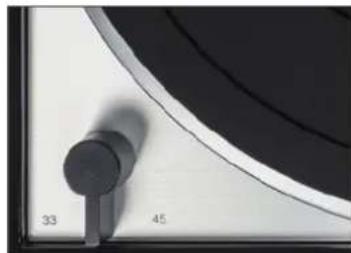
Fig. 11

Fig. 12
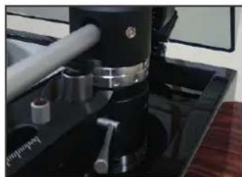
Fig. 13
893KQ
07.ДЯOTKIIUOHeHnI npINbOa CHOBa NOBepHIne nepeKIIIOuHaTeJIb B noJIOXKeHne «O». 3JIeKtpoDnBnIaTeJIb BblIKNIOuHaETcR I NICK OCTaHaBnIBaETcR.
08. Ecn npnnpbIbATEnb He nCnOJIb3yETcB TeHeHne IINTEJbHORo BpeMeH, OTKJIHOHTe 3NeKtpOnITaHne C3aDn Prn NOMOUs BbIKIOUaTeTn I yCTaHOBtE 3aUNTy INJIbI Ha CNCTeMy 3ByKOCHIMaTeJIa
3JIeKTPoHnKa npINBOJa IIOBOLaIeT HeNOCpeIcTBeHHO nepeKJIIOuA Tb CKOpocTb 6e3 IpeiBaPITeJbHOJ OCTaHOBKn DnCKa.
TEXHNUECKOE OBCJLYXKNBAHNE
3AMEHA IJIbI 3BYKOCHIMATEJIa
PnBBeHbIe Hxke yka3aHn OTHocTcK K NOCTaJIeHHoB B KOMnJIeKTe rOJIOBKe 3ByKOCHMaTeJIa OrtofON 2M Bronze n npyIM MoJeIeM cepu 2M
- YctaHOBNTe 3aUHTy IVIbI, OTBnHTnte HaKnIDHyIO raNky DePkaTeJI rOJIOBKN 3ByKOCHMaTeJI IN CHIMNTe erO C Tpy6Kn ToHapMa.
- CHOBA ydaJInte 3aIHTy IrgIbI IN CHIMITE ngIOpeXaTeIb B HAnpaBLeHn Bnepei.
- HanaHbTe HObI INrIIOpeXaTeJIb Ha Kopnyc CnCTeMbI.
- CHOBA yctaHOBNTe 3aunTy nIJIb I 3aPikCnpyte depKataBToIOBKn 3ByKOCHMaTeHa ToHapMe.
- Hactpoikn ToHapMa He HyxHO MeHrTb, ecJIN IcNoJIb3yeTcraIaIachaI aHaIIOrHyHOrO TIna.
Iry 3ByKOCHIMATEJI HyxHIO npOBepNTb IO nCTeueHn npimepHo 500 yacob 3KcnJyaTaUIN I np HEO6xoDIMOCTN 3aMeHHTb.
Ecn y Baceb comHeHn, npyHTe BbINOJIHeHne 3aMeHbI rOIOBKn 3ByKoCHMaTeJIa CBOEmy dJIepy nn DpyOMy KOMTteHTHomy JInUy.
BAKHAR PEKOMEHDAUHA
PeyraH OunuAte CBOI PnactNKn ObUHOn aHTnCTaTneCKO uETKo ININ NCIOJIb3yInTe MaunHy dIy OunchTKn PnactnOK. CJeNTe 3a YnCTOTOn aIma3HO NrIbl 3ByKOChMaTeJ. Iy OuchTKn LyuIwe Bcero nC- noB3yInTe He6oJIbUkyo KnCTOchKy. Prn 3tOM OCTOPOXHO npOBODTe NO aIma3HO NrIe B HappaBHeHn C3aDn Bnpeed.
TPAHCNOPTNPOBKA IPOINPbIBATEJI
Iyuwe BCero nCnoJb3ObaTb dIy TpaHCnOpTnpOBKn opunHahBHyU ynaKOBky yCTpoiCTBa. 3aFHKnpyte cy6waccn npn NOMoU nocTabJeHHbIX B KOMnEKeTpe TpaHCnOpTnpOBouhix BnHTOB. YCTaHOBtne 3aunTy Irgbln 3abNOKpyTe ToHApM B erO onope. JIy DInTeJIbHO TpaHCnOpTnpOBKn UIN nepeCbIKN OTBNHTITE DepKaTeJIb rOLOBKn 3ByKOCHMaTeJI n CHIMITE erO. 3aTeM ydaJIte npOTNBObEC B 3aHeN qACTn IN Ha-CTPOITe dIy aHTNCKeITnIHra 3HaueHne «O». PocNe 3TOrO CHIMITE ONOpHbI n NOMeCTtne erO haDHO KopobKn. BbInbTe nbIe3aUnTHyIO KpbIshKy n3 uapHnPoB n HaeXHo yNaKyIte ee.
3KcNEPTHbIE HACTPOIKN
3AMEHA TOLOBKIN 3BYKOCHMATEJIAR
IЯ 3aMeHb BCEI rOIOBKn 3ByKoCHMaTeJIHa npIyIO MOeJIb BbINOJHnTE OINCAHHBe HNKe DeiCTBna.
- YctaHOBNTe 3aUHTy IVIbI, OTBnHTnte DepeKaTeJIb TOLOBKn 3ByKOCHMaTeJIa IN CHIMITE eRO C Tpy6Kn ToHapMa.
- OTcoeINHInTe YetbIpe CBeTHbIX Ka6JIa OT BbIBOIOB Ha rOJIOBKe 3ByKOCHImaTeJIa IN BBIBHTInTE ee.
BvHTte HOByIO rOIOBky 3ByKOCHMaTeIe B depXkATEIb rOIOBKn 3ByKOCHMaTeIe I NOcOeHnIte Ka6e. nn. Poka He 3aTgNBaIte BVHTbl. - IepemEuAnTe rOIOBky 3ByKOCHImaTeJI B dEpaTeJI, NOKa He 6yDyT IOCTnHytbI NOxOJaUe BbiHOC HynEbbie TockN.ДЯЗTOrO HyKeH yCTaHOBOuHbI Lsa6JIoH.
- 3aTAHNTE BUNHTbl.
KpaChbI = CnHan Cnpaba
3eJIeHbIi = 3a3EmJIeHHe CπpaBa
6eJIbIi = CnHnAJI CNeBa
CINHNI=3a3eMJIeHNE CJEBA
Pn 3aMeHe BcE rOJOBKn 3ByKoCHMaTeJIryXHO 3aHOBO HAcTPONTb TOHApM, KaK ONICAHO BblIe.
TOJIOBK3BYKOCHIMATEJI C PA3HO COBCTBEHHOH MACCOI
IpoTINBOBc yCTaHOBJIeHHoro ToHapMa TP150 COCTOIT N3 DBYx qacte, YTObI MOXHO 6blIO HAdexKHO balaHCnPOBaTB rOJOBKN 3ByKOCHIMATEJIa C pa3HOJ CO6CTBeHHo MAccOI. Ipn 3OM Obe qACTN COeHNHeHb I DByM RAHTAMN, KOTOpBIe JERKO OTBnHUYBAIoTcR (PNC.13). Ondako peKOMeHNyETcR OTpeYInpOBAbT npOTINBOBec TaK, YTObI OH paCNoJARlca MaKcIMaJIbHO 6JI3KO K OCHOBaHHIO ToHapMa. 3TO HeoBXoDIMO, YTObI aΦΦeKT pbUra dIЯ TOHaPMA OCTaBAICr MINImaJIbHbIM. IOnToMy HxKHO cHaqana Bcerda nPoBepaTb, balaHCnpyETcRAI ToHApM pRn NOMOUs IByxCoeiHNHBIX rpy3OB. EcNI 3TO He ydaetc CdelaTb, OTBnHTITE 3aAnHO UacTh pIpOTINBOBeca. Ipi coeHNHeHbIX rpy3ax MOxHO balaHCnpoBaTb ToHapMbIC Co6CTBeHHo MAccOI npimepHo Do 30 rpaMM.

Pnc.13
HACTPOINKA A3IMMYTA
A3nMyT O3Haaye TnpaBnBbHbB BepTKKaNbHbI yroJ BxOJa aIma3HO Hblb 3ByKoCHMaTeJI B KaHaBKn PIIactINHK, TO ECTb PnB B3rJaDe CnepeDi aIma3Ha NfLa DOnKHa paCNoJa- rTaBc ToHNO nepEnDnKyIpyHO PnactINKe. IJn PpOBepKn IpOSe BCero nCNoJb3OBaTb 3epKaJIO, Ha KOTOpoe ONyCKaETcR fONOBKa 3ByKoCHMaTeJI.CNCTema 3ByKoCHMaTeJI IN
Pnc.14 Pnc.15
OTpaXeHHeOJIKbI Opa3OBbBaTb IINHIO 6e3 N3NOMA.
B kaueCTBe aJIbTePhaTINbI peKOMeHdyETcN cNOJb3OBA Tb pO3paHbI 7a6IOH C JInHnMn,Yepe3 KOTOpbI HeNoCpeIcTBeHHo BUndE HnepeKoc depXkAteJI N rOIOBKn 3ByKOCHImaTeJI. PpN OnpedeJIeHHbIX ObcToTJIbCTBax IaIg 3TOFO TAKKe MOxHO nCNOJb3OBA Tb o6bHbI TpaHCnOPTnP.
ПяКорpeкцИВОзMOЖHO IMeHUsEroCЯ OTKIOHeHЯ OT npaBnIbHOrO NOJIOKeHЯ TOHaPМ MOxHOrNoBepHyTb.
Дялгу hyжно ChЯть Кршky onopHoro 6Loka (pnc. 14) npn nomou majeHbKo WInueBOI OTBepTK, a 3aTeM CJIeRka Ocna6ntb pacnoJoxKeHHb IOn3y No ueHTpy BnT C KpeCToo6pa3HbIM WInueem (pnc. 15) (1).
OCTOPOXKHO: BnHT cIeNyET IINb CJIerKa OcIa6NtB, HN B KOem Cnyae He BbIBHnBuTe erO!
Iocne ocna6JIeHn BnHTa Tpy6Ky ToHaPMa MoKHO NOBOpaUBaTb Ha HeCKoJIbKO rpaYcoB B 06Ox HAnpaJIeHNax. PpN 3tOM NcToaHHo KOHTpOInPyTe TeKyuEe NoIOXKeHne PpN NOMOu 3epKaNa IIN LsAbloHa.
Cneinte 3a Tem, YTO6bI ToHApM HIKoTa He nepemelac B npOIObHOM HappaBHeHn, a DnIRaIc NCKJIIOuHTeJIbHO B CTOpOHbl.
HACTPOIKA TOHAPMA NO BBICOTE
Pn onpeHEnHbix 6cTcTeJIbCTBax B Cnyae 3aMeHbI rOJOBKn 3ByKOCHMaTeJ HxKHO OTkoppeKTIPOBaTb BBICOTy TOHaPM. Pn 3Tom DeIcTByET npakTNueCKoe npabNIO: TOHaPM Pn npONrPbIBAHm NpactINKn DOJXeH pacNoIarTaBC npaIIeNbHO ee NOBepXHOCTN npn B3rJaDe c6OKy. Ecnn 3TO He TaK, NOTOMY YTO HOBAr rOJOBKa 3ByKOCHMaTeJ
Pnc.16
yCTaHOBNeHa BbILIe IIN HNXe, HyXHO COOTBeTCTByIOUIM O6pa3OM aAnTnPoBaTb BbICOTy TOHApMa (pnc. 16).
Длгэ STOROTpe6yETc8 obbyHая KpeCTOBaY OTBepTKa (Ph2)и NOCTaBLeHHbI B KOMJIeKTe MTeaJIINueckn 7TnФТ.ДлгпрЕКИ NOdoIeT,HaPIMeP, TpaHCnOptIup NII pO3paHbI Sha6IOH C HaneYaTaHHbIMI npapallneHbIMI JInHIAIMI.
Chauana Hyxho Hemhoro OTBnHTb BNHT (1), DeCTByc c octopoxHocTbO. 3aTeM npn NOMOu WtncTa (2) CJeNyET NOBOPaHBaTB KOJIbC O HEO6XODIMOM HaPpABHeH, NOKa TOHaPM He DOCTNHT HyxHO BbICOTbI. Pocne 3TOrO CHOBA 3aTAHTE BNHT (1).
B HeKOTOpbIX cIyuaX MoXe TnoHaIObntbCpeYIpOBKa MInKpOINΦTa, TaK KaK ToHApM HaxoNTcR Ha Onope MInKpOINΦTa TAKKe B ONUeHHOM COCToHm JIb6 Oero HEnb3r NODHTb DOCTaTOHOb BBICOKo. BbICOTy MInKpOINΦTa MOxHO OTpeYIpOBaTb, OTBnHTNB BnHT (3).
HACTPOIKA HANPJAKEHENI PYKINH
Cy6waccn dOJxHO 6bITb TOUHO BbIPOBHeHO. KpOMe TOrO, OHO dOJXHO KOJIe6aTbCra CToPO NO BepTNKAni. He dOJXHO 6bITb HnKaKOrO 6bIeHnA, a TaKKe NpePena Da BbcOT. BblOnJIHnTe CJeDyUoUne DeIcTBnI dI npOBepKn I KOppeKTIpoBKn:
01.Cnerka Haxmte Ha onOpHbI DnCK B OJIaCTN CEHTpaIbHorO ⅢINHdJIeB HnPaBHeHn Bn3. NocpeIcTBOM 3TOrO aKTHnBnpyETcCy6uaccn, KOtOpoe DoJXHo Haatb paBHomepHo KJIe6aTbcra.
-
PpOBepbTe BbICOTy pIoUaIKn ToHApMa n BepxHeN pIoUaIKn. OBe OHn DoJIxHbI IMETb OdINHaKOBYIO BbICOTy. PpOBoJa IaIbIeM, Bbl He DoJIxHbI CyBCTBOBaTb nepenad BbICOT.
-
IpoBepbTe pacCToRHeIe OT HIXHEn KpOMKn DnCKa Do BepXHeN PLoUaKn. 3To paCCToRHeIe DOJHXHO 6bITb OINHaKOBbIM NO BCEI OKPVXHOCHTN DnCKa.
-
EcJIN BbICota, a TAKKe XapaKTePncTnK KOleBaHn COOTBeTCTBYOT ONuCAHnO, BCE B IopRdKe.
05.HanpoTIN,ecnHabJIOaIOTc6bHeHneNnonepeHbIE KOJIeBaHnCyBuaCCN NIN DNCK He paCNOJoxEH npaIIeBHO BEXHEIIOUaJIKe.HVXHO CKOPPEKTIPOBAtB HApRJeHHe IpyxHn.
-
CHIMITE pe3HOBBI MaT C ONOPHO DNCKA I NOBOPAHBAIte NOCJIeHN, NOKa YEpe3 6OJIbUHe OTBepCTN He CTaHyT BnHbI TPN PeryJINPOBOOHbIX BNHTA IINI npyKInH. OHn paCNOJOKeHbIB B VnDE TpeYrOJIbHNKa IOI DnCKOM. IOCTyn K Hm MOXHO NOLyHbTI NOCpeIcTBOM OTBepCTNI B INcKe (pnc.17, pnc.18).
-
Tenepb chepe3 OTBepCTnB DNICKe MOxHO OTPeRyIuPoBaTb HAnpJxHeHne TpeX KOHuecknx npyKIn npi NOMOUII IeCTNIgPaHHOro KJIoua 2,5 MM. Nytem BpaUeHn NO YacOBn CTpeJIke cy6Uaccn ONyCKaETcB B COOTBeTCTByIOUeM MeCTe, a pN IN BpaUeHn B DpyROM HApPabLeHn OHO NODHMaeTc. IepNoDUnueckn IPOBeprTe XapakTEpNCTKK KOJIeBAHn.
-
HacrpoKa YBnEeTc npaBnHoi, ecn cy6waccn KoJe6IeTc no BepTKaN, a pacctOHaHne ot dNCKa do BepxHe nnOuAaKn Be3Ne OOnHaKOBO.
При ИСпОЛьЗОВAHИng Руздддддддддддддддддддддддддддддддддддддддддддддддддддддддддддддддддддддддддддддддддддддддддддддддддддд徳нг.ТаК КсKуЗ OKa3bIBAeДОЛHInTeJbHyO HApY3Kу Ha ПPyxNHiI N DaBt Na HIX CBepx.ДЯ 3TOrO npyXnHbI HyxHO HeMHOrO OcIa6NtB,УTObI CHOBa YCTaHOBtB NOxOJaUyO BbICOTy.
TexHueckme xapaKTepeNCTMKN
PnBODHOmexaHn3M
PnBOD PemHb
3neKtpoBnuratel 3neKtpoBnuratel noCTOHHORTO TOKa
CKOpocn 331/3n4506/MNH
Hn3KoyactoTHa N BbICOKOyactoTHa 0,08% no DIN/cpeHeKaBpaTnHoe 3aueHne
TeToHaUNA
OnopHyI dNCK AIIOMMHIEBOE JINTBe IIOI DAJIeHHeM
DnameTp 12",300 MM
ToHapM Thorens TP150
TnCTaTueckn c6aJahncipOBaHHbI,J-0pa3HbI
3ΦΦeKTHBnA nnHa 9"/232,8 MM
30000000000000000000000000000000000000000000000000
Macca Bocnpoun3B0aJero yctpoNCTBa MAc. 30
BbHoc 17,8 MM
Hactpoika aHTnCKeTnIHra IpOToNBOBec C HHTbIO, npoxoJaIeu Hepe3 py6HOBbl Ja3ep
Tolobka 3ByKochImaTeJIa
Tun Ortofon 2M Bronze, MM
3aToyka nIblI PpeuHnHa Fine Line, 6e3 noKpbTna
Pa36aJIaHc KaHaIIOB 1d5/1K
BepnkaIbHbI yroI Bocnpou3BeDeHn 20°
Pekom. cnpotnbneHne harpy3kn 47000 OM
BbIXoHoe HapxkeHne 5,5MB(1KΓU,3,54cm/c)
TEXHINUeCKVEXAPAKTEPNUCTNIKIN
PnKmHa cna 1,5r+/-0,2r
Macca cnCTembl 7,2
Macca depkaTeI rONOBKn 3ByKOCHMaTeJI 13,5r (BKNIOHAA BnHTbI,raKyKa6eJIb)
AHAJIOROBbBbIXoD
Pa3beMbI RCA/TIOJIbNAH(no3OIOueHHbI)XLR
3NeKtpoNTaHne 100-240 B nepem. Toka, 50/60 Tc
3NeKtpoNtpe6JIeHne 6 BT
Pa3Mepb1(LxΓxB)440×370×180MM
TD 1500
To reduce risk of electric shock, do not remove the cover (or back). No user-serviceable parts inside.
WARNING
TO PREVENT FIRE OR SHOCK HAZARD, DO NOT EXPOSE THIS APPLIANCE TO RAIN OR MOISTURE.


EXPLANATION OF GRAPHICAL SYMBOLS
The lightning flash with arrowhead symbol, within an equilateral triangle, is intended to alert you to the presence of uninsulated 'dangerous voltage' within the product's enclosure that may be of sufficient magnitude to constitute an electric shock to persons.
The exclamation point within an equilateral triangle is intended to alert you to the presence of important operating and maintenance (servicing) instructions in the literature accompanying the appliance.

This product was tested and complies with all the requirements for the CE Mark.
Compliant to 2002/95/EC (RoHS)

IMPORTANT: DISPOSAL OF WASTE EQUIPMENT BY USERS IN PRIVATE HOUSEHOLDS IN THE EUROPEAN UNION
This symbol on the product or on its packaging indicates that this product must not be disposed off with your other household waste. Instead, it is your responsibility to dispose of your waste equipment by handing it over to a designated collection point for the recycling of waste electrical and electronic equipment. The separate collection and recycling of your waste equipment at the time of disposal will help to conserve natural resources and ensure that it is recycled in a manner that protects human health and the environment. For more information about where you can drop off your waste equipment for recycling, please contact your local city office, your household waste disposal service or the shop where you purchased the product.