TP 82 - Turntable THORENS - Free user manual and instructions
Find the device manual for free TP 82 THORENS in PDF.
| Brand | Thorens |
| Model | TP 82 |
| Product type | Tonearm for turntable |
| Effective length | 232.8 mm |
| Mounting distance | 215 mm |
| Overhang | 17.8 mm |
| Offset angle | 23.66° |
| Inner null | 66.0 mm |
| Outer null | 120.9 mm |
| Effective mass | 11 g |
| Total weight | 360 g |
| Maximum distortion between null points | 0.63% |
| Geometry | Bearwald / Lofgren « A » |
| Antiskating | By weight (adjustable over 6 grooves) |
| Connections | Separate cables (signal and ground) |
| Mounting hole diameter | 18 mm |
| Tracking force adjustment | By counterweight (large + eccentric) |
| Azimuth adjustment | By eccentric weight |
| Overhang adjustment | Up to +/-2.5 mm at headshell |
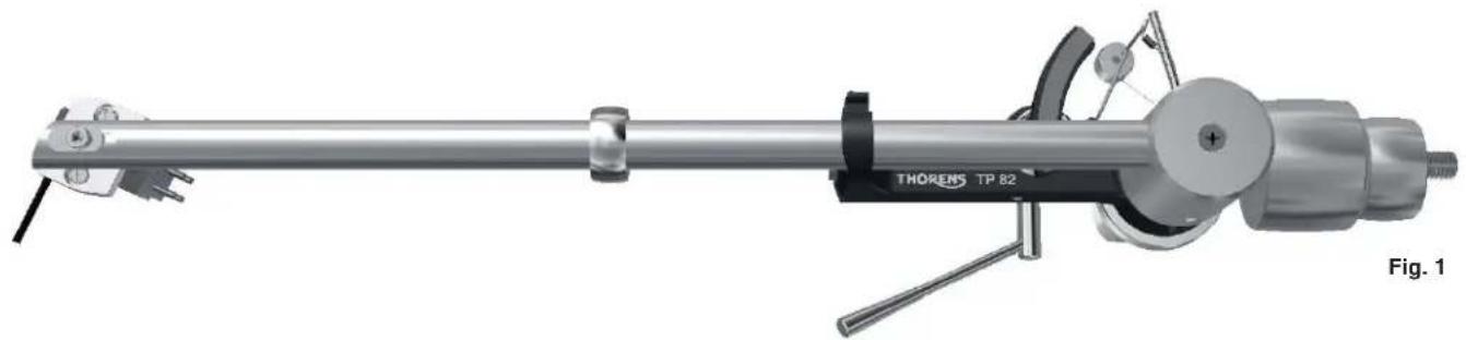
| Resonance damper | Ring on the tube (do not move) |
| Manufactured in | Germany |
Frequently Asked Questions - TP 82 THORENS
User questions about TP 82 THORENS
0 question about this device. Answer the ones you know or ask your own.
Ask a new question about this device
Download the instructions for your Turntable in PDF format for free! Find your manual TP 82 - THORENS and take your electronic device back in hand. On this page are published all the documents necessary for the use of your device. TP 82 by THORENS.
USER MANUAL TP 82 THORENS
natural_image
Pure electrical circuit lines without any symbolsTHORENS®
TP 82
Bedienungsanleitung
User Manual
Mode d'Emploi
www.thorens.com
TP 82
Bedienungsanleitung
User Manual
Mode d'Emploi
natural_image
Mechanical device with metallic lever and cylindrical body (no visible text or symbols)Inhalt
TONARM UND TONABNEHMERSYSTEM 6
AUFLAGEKRAFT 7
AZIMUT 8
ANTISKATINGKRAFT 9
natural_image
Mechanical assembly diagram of a Thorens TP 82 tool, showing shaft, housing, and mounting bracket (no text or symbols on the device itself)Aufl agekraft
natural_image
Mechanical assembly diagram showing a clamp and adjustment mechanism with arrows indicating motion (no text or symbols present)natural_image
3D mechanical assembly diagram showing a cylindrical component with a shaft and mounting base, no visible text or symbols
text_image
90° Abb. 4AAntiskatingkraft
natural_image
3D rendering of a mechanical assembly with no visible text or symbolsnatural_image
Close-up of a mechanical assembly with a tool and screw, set against a red background (no visible text or symbols)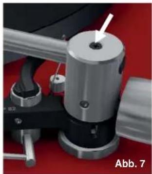
natural_image
Close-up of a mechanical device with a metallic cylindrical component and a white arrow pointing to a small hole, labeled 'Abb. 7' (no readable text or symbols beyond label)Technische Daten
TP 82
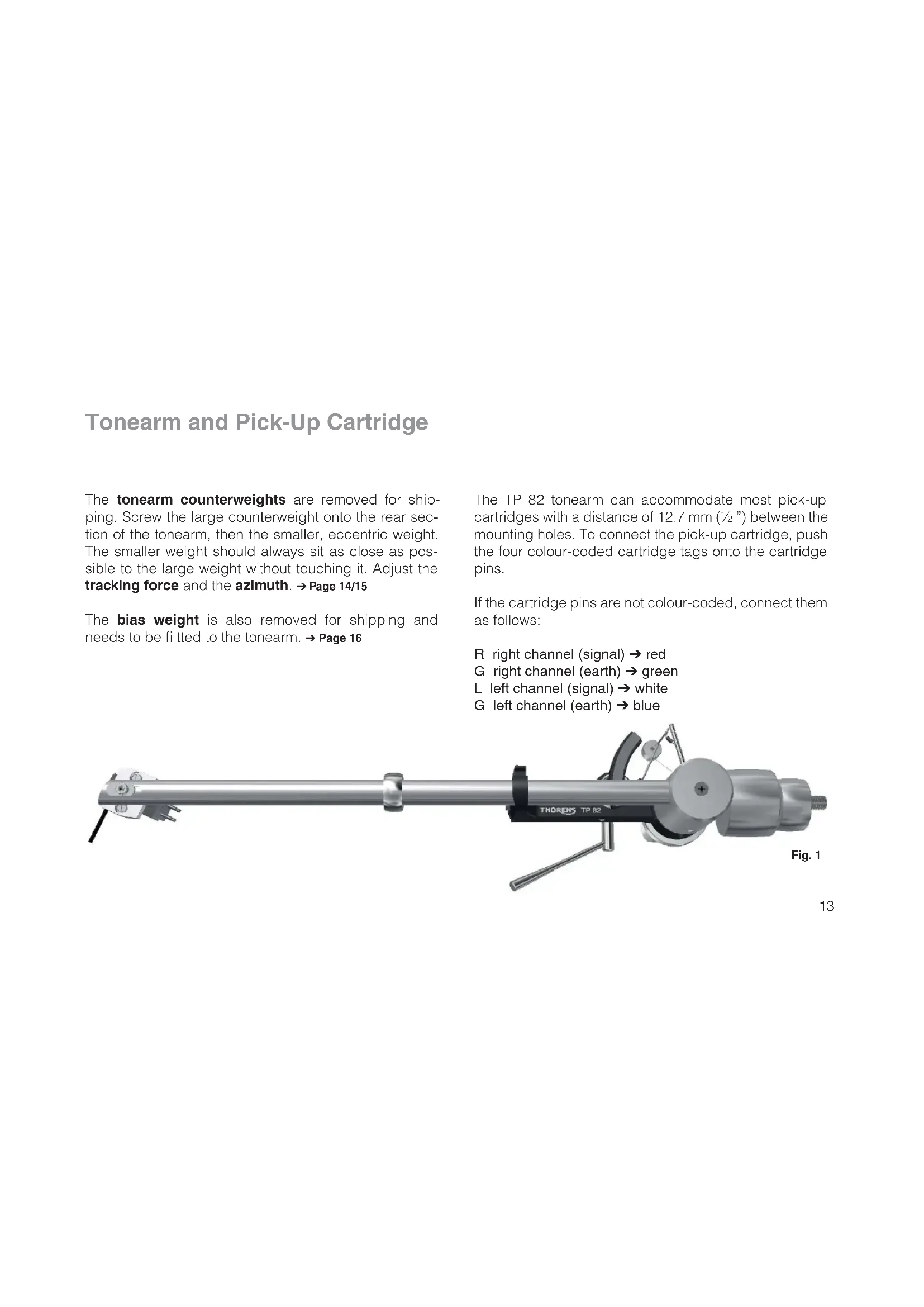
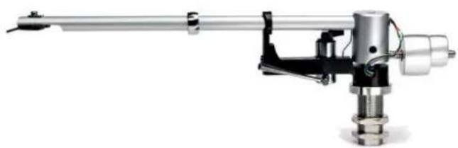
Tonearm and Pick-Up Cartridge
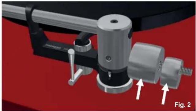
The tonearm counterweights are removed for shipping. Screw the large counterweight onto the rear section of the tonearm, then the smaller, eccentric weight. The smaller weight should always sit as close as possible to the large weight without touching it. Adjust the tracking force and the azimuth. → Page 14/15
The bias weight is also removed for shipping and needs to be fitted to the tonearm. → Page 16
The TP 82 tonearm can accommodate most pick-up cartridges with a distance of 12.7 mm ( 12 ") between the mounting holes. To connect the pick-up cartridge, push the four colour-coded cartridge tags onto the cartridge pins.
If the cartridge pins are not colour-coded, connect them as follows:
R right channel (signal) → red
G right channel (earth) → green
L left channel (signal) → white
G left channel (earth) → blue
natural_image
Mechanical assembly diagram of a Thorens TP 82 tool, showing shaft, housing, and mounting bracket (no text or symbols on the device itself)Tracking Force
The tracking force can be adjusted by rotating the to-nearm counterweights ( Fig. 2). The closer the counterweights are to the pick-up cartridge, the higher the tracking force. The smaller, eccentric weight is used to adjust the azimuth ( Page 15). It should sit as close as possible to the large weight without touching it.
The correct tracking force can be set with the help of the stylus gauge. Lower the tonearm lift, move the tonearm out over the platter and carefully lower it until the stylus of the pick-up cartridge comes to rest on the stylus gauge. The stylus guard must be removed for this procedure.
Great care should be taken to avoid damaging the stylus.
Note: Refer to the user manual of your pick-up cartridge to determine the correct tracking force.
natural_image
Mechanical assembly diagram showing a clamping device with two arrows indicating motion direction (no text or symbols present)Do not move the ring that sits around the middle of the tonearm tube ( Page 13, Fig. 1). It serves as a vibration damper and is effective only at its original position.
Azimuth
To adjust the azimuth, rotate the smaller, eccentric counterweight. → Fig. 3
The azimuth setting is correct when the pick-up cartridge is exactly perpendicular to the platter surface. → Fig. 4
natural_image
3D mechanical assembly diagram showing a cylindrical component with a shaft and mounting base, no visible text or symbols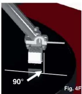
natural_image
Mechanical component diagram showing a 90-degree angle标注 (no text or symbols beyond label)Anti-Skating Force (Bias)
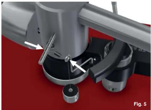
The interaction of stylus friction and cartridge bearing forces produces a force which pulls the tonearm towards the centre of the record (referred to as skating force). This force can be offset with the help of anti-skating force, which, in the case of the TP 82, is produced by a bias weight.
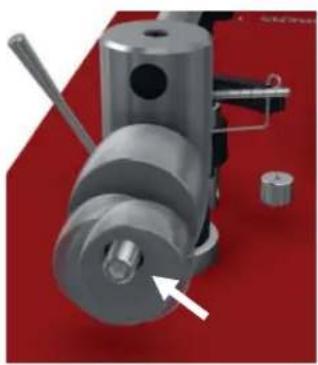
Lead the bias weight string through the hanger guide and hook the string's loop over the tonearm's bias shaft ( Fig. 5).
The string can be located in one of six grooves on the bias shaft. The further out the string loop on the bias shaft, the higher the anti-skating force. The amount of anti-skating force required depends on the type of pick-up cartridge and the tracking force used.
natural_image
3D rendering of a mechanical assembly with no visible text or symbolsThe amount of anti-skating force required depends on the type of pick-up cartridge used. If you change the cartridge for a different type, use a test record to determine how much anti-skating force is required.
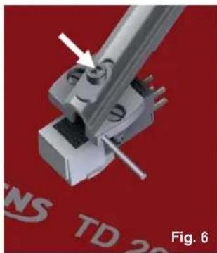
Further Tonearm Adjustments
The tonearm headshell allows an overhang adjustment of ±2.5 mm to be made, which may be necessary when installing a new pick-up cartridge. To adjust overhang, loosen the screw holding the headshell and move the headshell as required. → Fig. 6
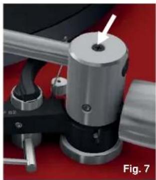
Overhang can be further adjusted by +2.5 mm at the rear of the tonearm. To do so, loosen the screw at the top of the bearing housing by one or two turns at most and move the tonearm tube as required. → Fig. 7
The screw at the top of the bearing housing must not be loosened too far, let alone removed completely, as this may result in damage to the tonearm!
Take care not to over-tighten the screws after making adjustments.
natural_image
3D mechanical assembly diagram showing a pin inserted into a housing component, with no visible text or symbols.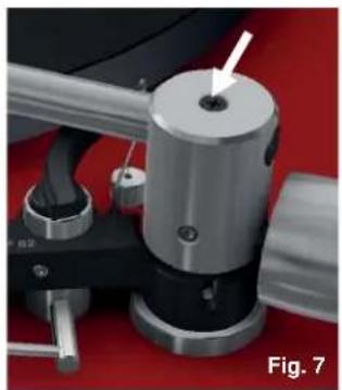
natural_image
Close-up of a mechanical device with a metallic cylindrical component and a white arrow pointing to a hole, labeled 'Fig. 7' (no readable text or symbols on the device itself)Technical Specifications
| TP 82 | |
| Tonearm specifi cation | 9" |
| Distance tonearm pivot to stylus | 215mm |
| Effective length | 232,8mm |
| Stylus overhang | 17,8mm |
| Angular offset | 23,66° |
| Inner null | 66,0mm |
| Outer null | 120,9mm |
| Effective mass | 11g |
| Maximum distortion between null-points | 0,63% |
| Geometry | Bearwald / Löfgren „A“ |
| Weight | 360g |
| Connestors | wires for soldering |
| Mounting hole | 18mm dia |
| Antiskating | by weight |
Technical specifications subject to change without notice. Made in Germany.
Notes
natural_image
Mechanical assembly diagram of a Thorens TP 82 tool, showing shaft, housing, and mounting bracket (no text or symbols on the device itself)Force d'appui
natural_image
Close-up of a mechanical clamp or fixture with metallic components and a red background (no visible text or symbols)natural_image
3D mechanical assembly diagram showing a cylindrical component with a shaft and mounting base, no visible text or symbols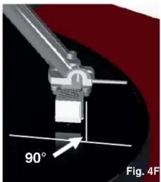
natural_image
Close-up of a mechanical component with a 90-degree angle标注 and 'Fig. 4F' label (no other text or symbols)Force antiskating
natural_image
Mechanical assembly diagram showing a rotating device with labeled parts and directional arrows (no readable text or symbols)natural_image
3D mechanical assembly diagram showing a bracket with a tool and mounting base, no visible text or symbols