DM200A - Multimeter GREENLEE - Free user manual and instructions
Find the device manual for free DM200A GREENLEE in PDF.
| Product Type | Portable Digital Multimeter |
| Brand | Greenlee |
| Model | DM200A |
| Display | LCD 4-digit (max 6000) with backlight and 24-segment bar graph |
| Power Supply | 2 AAA 1.5V batteries (NEDA 24A or IEC LR03) |
| Battery Life | Approximately 34 minutes of inactivity before auto power off |
| Measurement Functions | AC/DC voltage (up to 1000 V), AC/DC current (up to 8 A), resistance (up to 60 MΩ), frequency, diode test, audible continuity |
| Input Impedance (voltage) | 10 MΩ // 50 pF |
| DC Voltage Accuracy | ± (0.2% + 3 digits) on 1000 V |
| AC Voltage Accuracy (50-400 Hz) | ± (1.0% + 5 digits) on 1000 V |
| Input Protection | Fuse 0.63A/500V (mA/μA), fuse 10A/600V (A) |
| Overvoltage Categories | CAT II 1000 V, CAT III 600 V, CAT IV 300 V (ΩV terminal) |
| Special Functions | Non-contact electric field detection (EF), Beep-Jack™ (incorrect connection alert), data hold (HOLD), relative zero (REL), manual range selection (RANGE) |
| Operating Temperature | 0 °C to 40 °C, humidity 80% max |
| Storage Temperature | -20 °C to 60 °C |
| Maximum Altitude | 2000 m |
| Approximate Weight | 200 g (with batteries) |
| Dimensions | 150 x 70 x 30 mm (approx) |
| Warranty | Limited Lifetime Warranty |
| Maintenance and Cleaning | Clean the housing with a damp cloth and mild detergent. Do not use solvents. |
| Spare Parts and Repairability | Batteries and fuses are user-replaceable. No user-serviceable parts inside. |
| Optional Accessories | DMSC-2U computer interface with software for measurement logging |
Frequently Asked Questions - DM200A GREENLEE
User questions about DM200A GREENLEE
0 question about this device. Answer the ones you know or ask your own.
Ask a new question about this device
Download the instructions for your Multimeter in PDF format for free! Find your manual DM200A - GREENLEE and take your electronic device back in hand. On this page are published all the documents necessary for the use of your device. DM200A by GREENLEE.
USER MANUAL DM200A GREENLEE
natural_image
Abstract geometric logo with a black diamond containing the letter 'G' (no text or symbols beyond the emblem)GREENLEE®
A Textron Company
text_image
8.000 SELECT RANGE Rel CF REC CREST ~ V Ω Temp mV A mA OFF μA Auto Check (I+2) mA μA Temp DV A- A COM MAX 3.6A MAX 6A MAX 10A MAX 15A MAX 20A MAX 25A MAX 30A MAX 35A MAX 40A MAX 45A MAX 50A MAX 55A MAX 60A MAX 65A MAX 70A MAX 75A MAX 80A MAX 85A MAX 90A MAX 95A MAX 100A MAX 105A MAX 110A MAX 115A MAX 120A MAX 125A MAX 130A MAX 135A MAX 140A MAX 145A MAX 150A MAX 155A MAX 160A MAX 165A MAX 170A MAX 175A MAX 180A MAX 185A MAX 190A MAX 195A MAX 200A MAX 205A MAX 210A MAX 215A MAX 220A MAX 225A MAX 230A MAX 235A MAX 240A MAX 245A MAX 250A MAX 255A MAX 260A MAX 265A MAX 270A MAX 275A MAX 280A MAX 285A MAX 290A MAX 295A MAX 300A MAX 305A MAX 310A MAX 315A MAX 320A MAX 325A MAX 330A MAX 335A MAX 340A MAX 345A MAX 350A MAX 355A MAX 360A MAX 365A MAX 370A MAX 375A MAX 380A MAX 385A MAX 390A MAX 395A MAX 400A MAX 405A MAX 410A MAX 415A MAX 420A MAX 425A MAX 430A MAX 435A MAX 440A MAX 445a MAX 3.6A MAX 6.6B MAX 10.6C MAX 3.6B MAX 6.6C MAX 3.6C MAX 3.6D MAX 3.6E MAX 3.6F MAX 3.6G MAX 3.6H MAX 3.6I MAX 3.6J MAX 3.6K MAX 3.6L MAX 3.6M MAX 3.6N MAX 3.6O MAX 3.6P MAX 3.6Q MAX 3.6R MAX 3.6S MAX 3.6T MAX 3.6U MAX 3.6V MAX 3.6W MAX 3.6X MAX 3.6Y MAX 3.6Z MAX 3.6D MAX 3.6E MAX 3.6F MAX 3.6G MAX 3.6H MAX 3.6I MAX 3.6J MAX 3.6K MAX 3.6L MAX 3.6M MAX 3.6N MAX 3.6P MAX 3.6Q MAX 3.6Y MAX 3.6Z MAX 3.6D MAX 3.6E MAX 3.6W MAX 3.6I MAX 3.6J MAX 3.6K MAX 3.6H MAX 3.6I MAX 3.6Z MAX 3.6D MAX 3.6E MAX 3.6W MAX 3.6I MAX 3.6J MAX 3.6K MAX 3.6H MAX 3.6I MAX 3.6Z MAX 3.6D MAX 3.6E MAX 3.6W MAX 3.6I Max Max Max Max Max Max Max Max Max Max Max Max Max Max Max Max Max Max Max Max Max Max Max Max Max Max Max Max Max Max Max Max Max Max Max Max Max Max Max Max Max Max Max Max Max Max Max Max Max Max Max Max Max Max Max Max Max Max Max Max Max Max Max Max Max Max Max Max Max Max Max Max Max Max Max Max Max Max Max Max Max Max Max Max Max Max Max Max Max Max Max Max Max Max Max Max Max Max Max Max Max MinEnglish .....1–24
Français ......25–48
Italiano ....49–72
Deutsch....73–96
Español....97–120
Read and understand all of the instructions and safety information in this manual before operating or servicing this tool.
Register this product at www.greenlee.com
Description
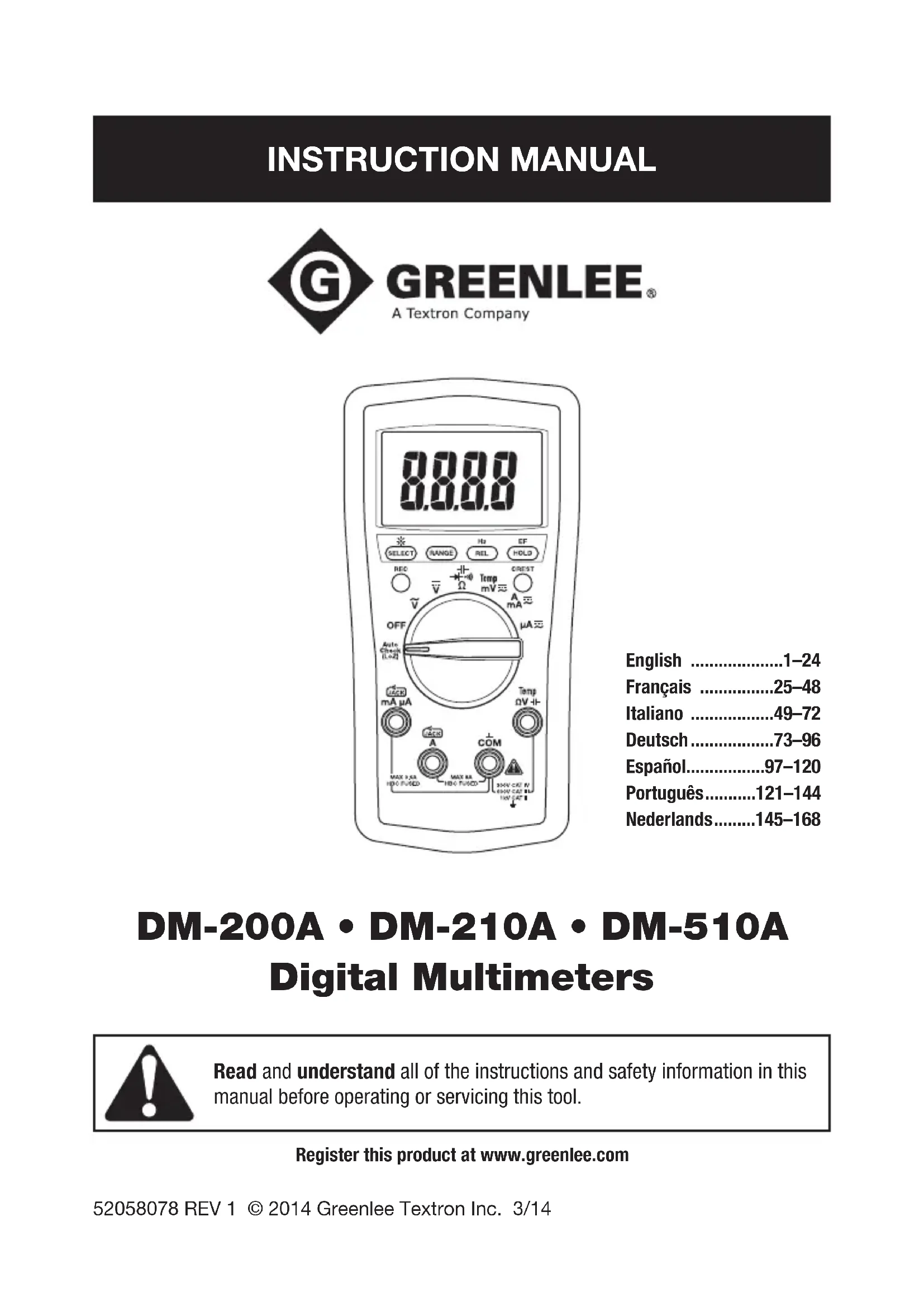
The Greenlee DM-200A, DM-210A, and DM-510A Digital Multimeters are hand-held testing devices with the following measurement capabilities: AC and DC voltage, AC and DC current, frequency, and resistance. They also check diodes and verify continuity. An optional optically isolated computer interface with software facilitates the recording of readings from the meter to a computer.
Other specialized capabilities and functions common to all meters include:
- Backlighted LCD for reading in dim conditions.
- Beep-Jack™ audible warning alerts the user with a beep and an error message on the LCD if the test lead is plugged into the mA/μA or A input terminal while the selector switch is not in the mA/μA or A position.
• Non-contact and single-probe voltage detection capability. - Bar graph display, which responds more quickly than the numeric display — useful for detecting faulty contacts, potentiometer clicks, and signal spikes.
- Relative zero mode.
- Data hold mode.
- Selectable automatic power off.
The DM-210A and DM-510A multimeters have the following additional capabilities: temperature (K-type thermocouples only) and capacitance.
The DM-510A multimeter has an AutoCheck™ function for automatic selection of AC voltage, DC voltage, and resistance with low input impedance to mask “ghost” voltages. The DM-510A also has a crest function, which captures voltage or current signal peaks, as well as a recording function, which stores the maximum and minimum input readings. The DM-510A is a true RMS meter.
Safety
Safety is essential in the use and maintenance of Greenlee tools and equipment. This instruction manual and any markings on the tool provide information for avoiding hazards and unsafe practices related to the use of this tool. Observe all of the safety information provided.
Purpose of This Manual
This instruction manual is intended to familiarize all personnel with the safe operation and maintenance procedures for the Greenlee DM-200A, DM-210A, and DM-510A Digital Multimeters
Keep this manual available to all personnel. Replacement manuals are available upon request at no charge at www.greenlee.com.

Do not discard this product or throw away!
For recycling information, go to www.greenlee.com.
Important Safety Information

SAFETY ALERT SYMBOL
This symbol is used to call your attention to hazards or unsafe practices which could result in an injury or property damage. The signal word, defined below, indicates the severity of the hazard. The message after the signal word provides information for preventing or avoiding the hazard.
DANGER
Immediate hazards which, if not avoided, WILL result in severe injury or death.
WARNING
Hazards which, if not avoided, COULD result in severe injury or death.
CAUTION
Hazards or unsafe practices which, if not avoided, MAY result in injury or property damage.

natural_image
Illustration of a hand interacting with an open book (no text or symbols visible)WARNING
Read and understand this material before operating or servicing this equipment. Failure to understand how to safely operate this tool could result in an accident causing serious injury or death.

WARNING
Electric shock hazard: Contact with live circuits could result in severe injury or death.
All specifications are nominal and may change as design improvements occur. Greenlee Textron Inc. shall not be liable for damages resulting from misapplication or misuse of its products.
® Registered: The color green for electrical test instruments is a registered trademark of Textron Innovations Inc.
AutoCheck and Beep-Jack are trademarks of BTC.
Microsoft and Windows are registered trademarks of Microsoft Corporation.
Important Safety Information
WARNING
Electric shock and fire hazard:
- Do not expose this unit to rain or moisture.
- Do not use the unit if it is wet or damaged.
- Use test leads or accessories that are appropriate for the application. Refer to the category and voltage rating of the test lead or accessory.
- Inspect the test leads or accessory before use. They must be clean and dry, and the insulation must be in good condition.
- Use this unit for the manufacturer's intended purpose only, as described in this manual. Any other use can impair the protection provided by the unit.
Failure to observe these warnings could result in severe injury or death.
WARNING
Electric shock hazard:
- Do not apply more than the rated voltage between any two input terminals, or between any input terminal and earth ground.
- Do not contact the test lead tips or any uninsulated portion of the accessory.
Failure to observe these warnings could result in severe injury or death.
WARNING
Electric shock hazard:
- Do not operate with the case open.
- Before opening the case, remove the test leads from the circuit and shut off the unit.
Failure to observe these warnings could result in severe injury or death.
WARNING
Electric shock hazard:
The fuses are an integral part of the overvoltage protection. When fuse replacement is necessary, refer to “Specifications” for the correct type, size, and capacity. Using any other type of fuse will void the overvoltage protection rating of the unit.
Failure to observe this warning could result in severe injury or death.
Important Safety Information
WARNING
Electric shock hazard:
- Unless measuring voltage, current, or frequency, shut off and lock out power. Make sure that all capacitors are discharged. Voltage must not be present.
- Set the selector and connect the test leads so that they correspond to the intended measurement. Incorrect settings or connections can result in a blown fuse.
- Using this unit near equipment that generates electromagnetic interference can result in unstable or inaccurate readings.
Failure to observe these warnings could result in severe injury or death.
CAUTION
Electric shock hazard:
Do not change the measurement function while the test leads are connected to a component or circuit.
Failure to observe this precaution may result in injury and can damage the unit.
CAUTION
Electric shock hazard:
Do not use the tester to measure voltages in circuits that could be damaged or activated by the AutoCheck™ mode's low input impedance (approximately 2.5 kΩ and 120 pF).
Failure to observe this precaution may result in injury and can damage the unit.
CAUTION
Electric shock hazard:
- Do not attempt to repair this unit. It contains no user-serviceable parts.
- Do not expose the unit to extremes in temperature or high humidity. Refer to “Specifications.”
Failure to observe these precautions may result in injury and can damage the unit.
Identification
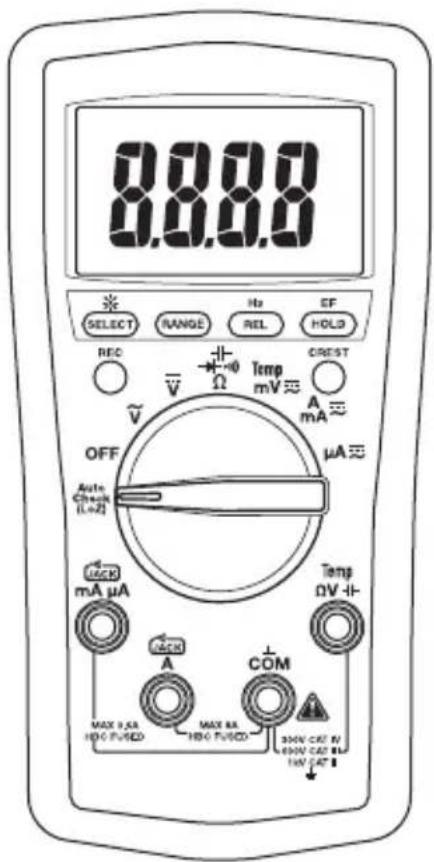
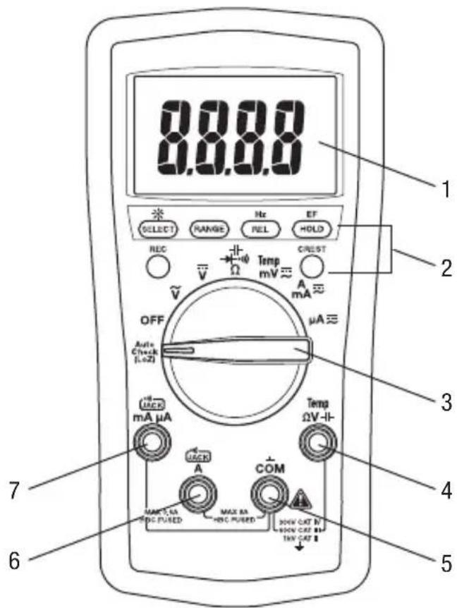
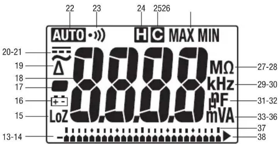
- Display 4-digit LCD (maximum reading is 5999) and bar graph.
- Feature buttons Refer to explanations in the "Using the Features" section.
- Selector Selects a function or turns power OFF.
- V -11 Positive input terminal for all measurements except current.
- COM Negative, common, or ground input terminal for all measurements.
- A Positive input terminal for high current measurements.
- mA μA Positive input terminal for low current measurements.
text_image
0.0.0.0 1 2 3 4 5 6 7 8 9 10 11 12 13 14 15 16 17 18 19 20 21 22 23 24 25 26 27 28 29 30 31 32 33 34 35 36 37 38 39 40 41 42 43 44 45 46 47 48 49 50 51 52 53 54 55 56 57 58 59 60 61 62 63 64 65 66 67 68 69 70 71 72 73 74 75 76 77 78 79 80 81 82 83 84 85 86 87 88 89 90 91 92 93 94 95 96 97 98 99 100Display Icons
- Bar graph element
-
- Polarity indicator for bar graph
- LoZ Low input impedance is active.
- Low battery
- – Polarity indicator
- 8.8.8.8 Numeric display
- Relative zero function is enabled.
- AC measurement is selected.
- =DC measurement is selected.
- Automatic ranging is enabled.
- Continuity
- Hold function is enabled.
- Crest capture function is enabled.
- MAX Maximum is displayed or being recorded.
MIN Minimum is displayed or being recorded.
- M Mega ( 10^6 )
- Ohm
- k Kilo (10 3)
- Hz Hertz (frequency in cycles per second)
- n Nano (10 ^-9 )
- F Farad
- μ Micro (10 ^-6 )
- m Milli (10 ^-3 )
- V Volt
- A Ampere
- Bar graph scale
- ▶ Overload (bar graph display)
text_image
AUTO • »» 22 23 24 2526 H C MAX MIN 20-21 19 18 17 16 15 LoZ 0.00.0 MΩ kHz pF mVA 27-28 29-30 31-32 33-36 37 38 13-14Using the Features
All Models
- SELECT: Press momentarily to toggle between functions.
- ☀: Press and hold until backlight illuminates. Press and hold again to turn off. The backlight automatically turns off after approximately 30 seconds to extend battery life.
- RANGE: Press once to enter the manual ranging mode. The AUTO icon will disappear from the display. Press repeatedly to step through the ranges. Press and hold to return to the automatic ranging mode.
Note: When using MAX/MIN, HOLD, or mode, pressing RANGE will cause the meter to exit that mode.
- REL: Finds the difference between two measurements. While taking a measurement, press REL to set the display to zero. The icon will appear on the display. Take the second measurement. The value on the display will be the difference between the two measurements. Press again to exit this mode.
- Hz: Press and hold until the meter beeps to enable frequency measurement. The frequency function can be used with the selector in any voltage or current setting. Use the V or A settings for measuring the frequency of sinusoidal waveforms. Use the mV setting for measuring the frequency of 3 volt or 5 volt logic level, square waveform signals.
The sensitivity of the frequency measurement function varies with the measurement range. To automatically select a sensitivity level, measure the voltage or current first, and then press Hz. If the reading becomes unstable or reads zero, press the RANGE button to select a different sensitivity level.
The number of bar graph elements indicates the sensitivity selected:
- 1 element = 6 V, 6 A, 60 mA, or 600 μA
- 2 elements = 60 V, 10 A, 600 mA, or 6000 μA
- 3 elements = 600 V
-
4 elements = 1000 V
-
HOLD H: Press momentarily to hold the present value on the display. Press again to exit this mode. This feature does not affect the bar graph.
- EF: Set the meter to any current or voltage function. Press and hold until the meter beeps to detect the electric field that surrounds current-carrying conductors. Signal strength is displayed as a series of dashes on the display.
- Use the tester's built-in antenna (located along the top, near the LCD) for tracing live circuits or locating a break in a wire.
- For more precision, such as distinguishing between current-carrying and ground wires, connect a test lead to the V input terminal and use it as a probe for direct contact verification of AC voltage.
- Automatic Power Off: To extend battery life, the meter will shut itself off after approximately 30 minutes of inactivity. To restore power, press either the SELECT, CREST, or REC button or turn the selector to OFF and then back on. To disable this feature, press SELECT while turning the meter on.
Using the Features (cont'd)
- Disabling the Beeper: Hold down the RANGE button while turning the meter on to temporarily disable the beeper feature. Turn the selector to OFF and then back on to enable the beeper.
DM-510A Only
- Low Impedance AutoCheck™ Mode: In this mode, the meter automatically selects the proper measurement based on the input.
- If there is no input, "Auto" appears on the display.
- If the voltage is above approximately 1 volt AC or DC, voltage is displayed.
- If both AC and DC voltages are present, the larger voltage is displayed.
- If no voltage is present and there is resistance less than approximately 10 MΩ, resistance is displayed. If the measured resistance is below the continuity threshold (between 10 Ω and 80 Ω), then the continuity tone will sound.
This mode features low input impedance to mask stray or “ghost” voltage pickup. The input impedance is approximately 2.5 kΩ at low voltage, increasing to approximately 375 kΩ at 1000 V.
The symbol “LoZ” indicates that the meter is in a low impedance mode. Do not use the AutoCheck™ mode on circuits that could be damaged or activated by such low input impedance. Instead use the selector to select the high impedance AC or DC volts modes to minimize loading for such circuits.
Range-Lock and Function Feature: While in the AutoCheck™ mode, press the SELECT button momentarily to lock the displayed function. Press the RANGE button momentarily to lock the displayed measurement range. Press either button repeatedly to step through the ranges or functions.
Energized Circuit Alert: If the resistance mode is locked in the AutoCheck™ mode and the leads are placed across an energized circuit, the meter will emit an audible warning tone.
- REC: Press momentarily to activate the MAX/MIN recording mode. The input value is measured every 50 ms in this mode. “MAX MIN” will appear on the display. The LCD will display the actual input value. The meter will beep whenever the maximum or minimum is updated. Press repeatedly to select the desired display: maximum, minimum, or actual input. Press and hold to exit this mode.
The automatic power off feature is disabled when using this function.
- CREST: Press momentarily to activate the crest recording mode. The input value is measured every 5 ms in this mode. 📂 and “MAX” will appear on the display. The LCD will display the maximum crest value. Press repeatedly to select the desired display: maximum or minimum crest value. Press and hold to exit this mode.
Automatic ranging and automatic power off are disabled when using this function.
AC Measurement
AC measurements are usually displayed as RMS (root mean square) values. The RMS value is equal to the value of a DC waveform, which would deliver the same power if it replaced the time-varying waveform. Two AC measurement methods are average-responding RMS calibrated and true RMS-reading.
The average-responding RMS calibrated method takes the average value of the input signal after full wave rectification, multiplies it by 1.11, and displays the result. This method is accurate if the input signal is a pure sine wave. The DM-200A and DM-210A are average-responding meters.
The true RMS-reading method uses internal circuitry to read the true RMS value. This method is accurate, within the specified crest factor limitations, whether the input signal is a pure sine wave, square wave, triangle wave, half wave, or signal with harmonics. The ability to read true RMS provides much more measurement versatility. The DM-510A is a true RMS meter.
The Waveforms and Crest Factors table shows some typical AC signals and their RMS values.
Waveforms and Crest Factors
| Waveform |  |  |  |  |
| RMS Value 100 | 100 100 100 | |||
| Average Value 90 | 100 87 64 | |||
| Crest Factor* (ξ) | 1.414 1 1.73 | 2 |
* The crest factor is the ratio of the peak value to the RMS value; it is represented by the Greek letter .
Using the Optional Software
These meters are compatible with Greenlee DMSC-2U, an optically isolated computer interface cable and software. It allows measurements to be logged to a personal computer using the Microsoft® Windows® operating system.
natural_image
Simple rounded rectangle outline with no text or symbolsInstalling the Software
- Insert the CD into the computer's CDROM drive.
- The installation program should launch automatically. If it does not, double click on the CD icon in "My Computer."
- The installation program menu will appear. Click on "Software Installation."
- Type your meter's catalog number (for example, "DM-510A") in the dialog box.
- Complete the remaining dialog boxes according to user preferences.
- Refer to the program's Readme file for instructions on using the software.
Connecting the Optical Interface Cable
- Align the interface with the slot on the back of the meter. The cable must point to the left.
- Push the interface into the slot.
- For USB applications, proceed to step 5.
- For RS-232 applications, connect the interface cable to a serial port on the computer, and proceed to step 8.
- Connect the interface cable to the RS-232-to-USB adapter supplied with DMSC-2U.
- Connect the square end of the USB cable to the RS-232-to-USB adapter.
- Connect the other end of the USB cable to the computer.
- Press the HOLD button while turning the meter on to enable its communication capabilities.
Operation

WARNING
Electric shock hazard:
Contact with live circuits could result in severe injury or death.
- Refer to the Settings Table. Set the selector to the proper setting, press SELECT (when instructed to do so), and connect the test leads to the meter.
- Refer to "Typical Measurements" for specific measurement instructions.
-
Test the unit on a known functioning circuit or component.
-
If the unit does not function as expected on a known functioning circuit, replace the battery and/or fuses.
-
If the unit still does not function as expected, call Greenlee for technical assistance at +1-815-397-7070.
-
Take the reading from the circuit or component to be tested.
Settings Table
| To measure this characteristic ... | Set the selector to this symbol ... | These icons will appear on the display ... | Connect the red lead to ... | Connect the black lead to ... |
| All Models | ||||
| Voltage(1000 V max) |  |  | ΩV COM | |
 |  | |||
| Resistance |  |  | ΩV COM | |
| Continuity* | Ω |  | ||
| Diode |  | |||
| Voltage (600 mV max)** |  | mV ΩV COM | ||
| Current (8 A max)** |  |   | A COM | |
| Current (600 mA max)** |  |  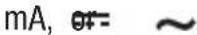 | mA μA COM | |
| Current (6000 μA max)** | [DSTW] |  [5083] [5083] | mA μA COM | |
This table continues on the next page.
Operation (cont'd)
Settings Table (cont'd)
| To measure this characteristic ... | Set the selector to this symbol ... | These icons will appear on the display ... | Connect the red lead to ... | Connect the black lead to ... |
| All Models (cont'd) | ||||
| Frequency—Line Level Voltage or Current | , A, mA, or μA and press Hz | Hz ΩV COM | ||
| Frequency—Logic Level*** mV | and press Hz Hz ΩV | COM | ||
| EF single probe† | Any voltage or current function and press EF for at least 1 second | E.F. | ΩV | — |
| EF non-contact† | —— | |||
| DM-210A and DM-510A Only | ||||
| Capacitance†† | 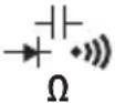 and press SELECT and press SELECT |  nF nF |  | COM |
| Temperature Temp | C or F (press SELECT to change scale) | Temp ΩV -I+ | COM | |
| DM-510A Only | ||||
| Auto select AC volts, DC volts, resistance, and continuity (low impedance measurement) | AutoCheck | Auto and LoZ | Temp ΩV -I+ | COM |
* Tone indicates continuity. The threshold is between 10 Ω and 80 Ω.
** Press SELECT for AC or DC, as required.
*** Logic level frequency has a fixed sensitivity and is for digital signals. Refer to “Accuracy”.
† Refer to the “Using the Features” section for an explanation of EF (electric field detection).
†† Discharge capacitor before measurement. Discharge a large capacitor through an appropriate resistive load.
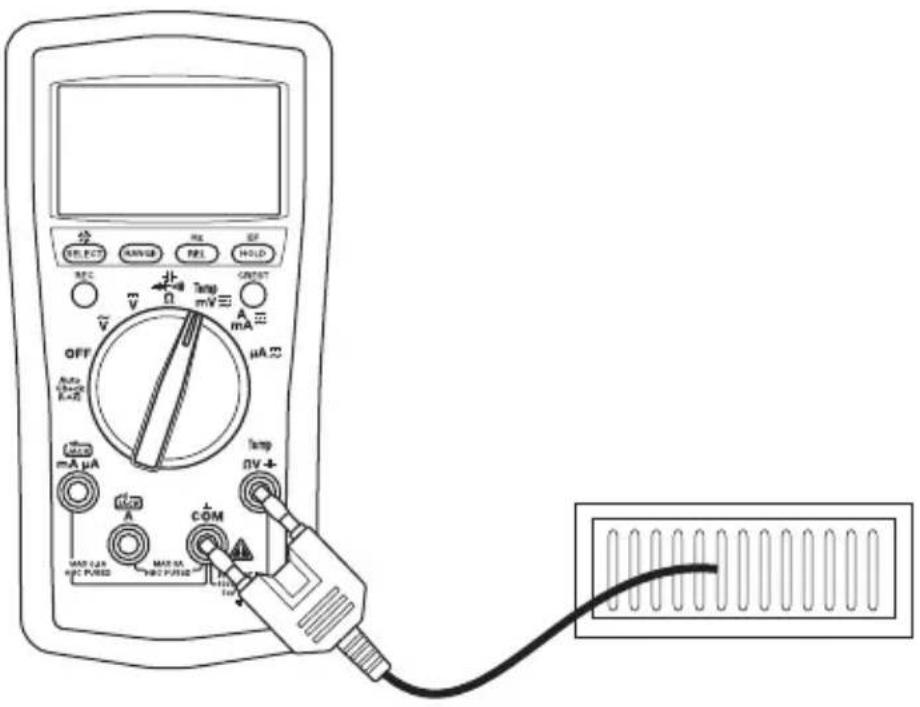
Typical Measurements
Voltage Measurement
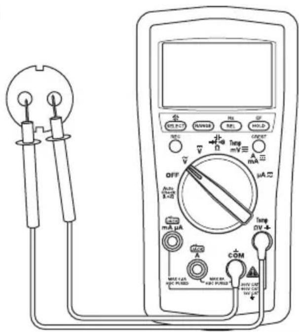
text_image
Diagram of an analog multimeter with labeled components including voltage source, switch, and display screenCurrent Measurement
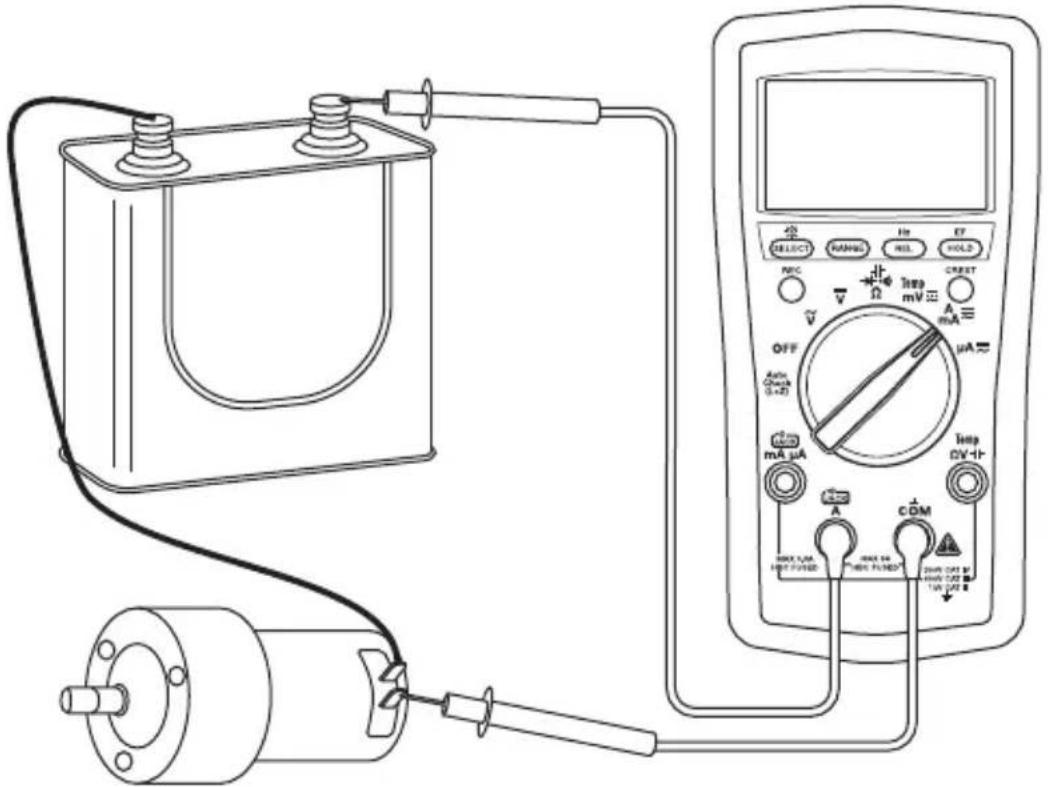
text_image
Diagram of an electrical testing setup with labeled components including battery, switch, voltmeter, and motorTypical Measurements
Resistance Measurement
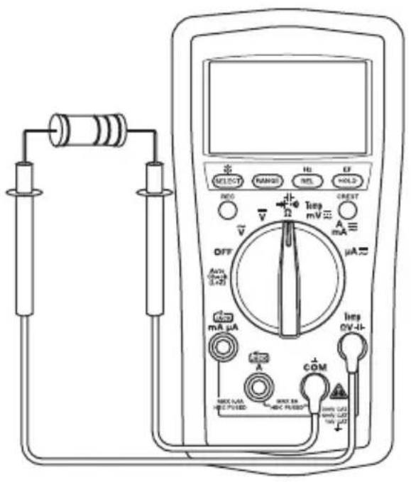
text_image
Diagram of a multimeter with labeled components including range selector, voltage meter, and current meter.Continuity Check
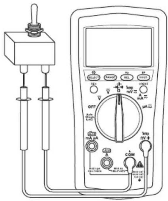
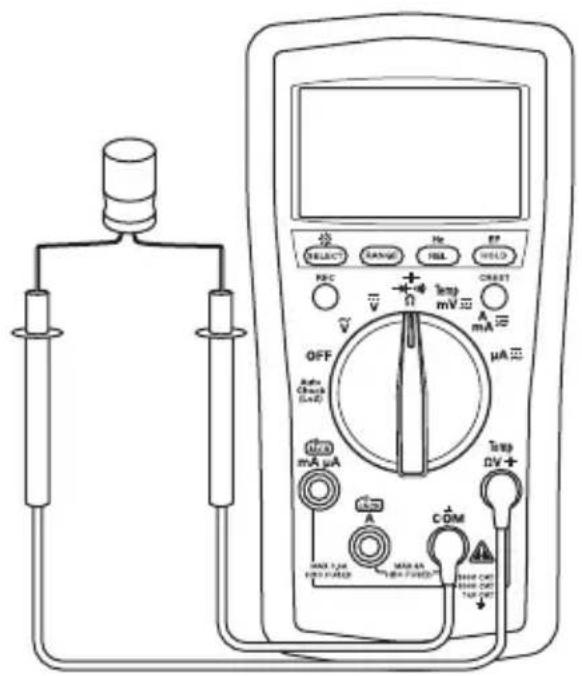
text_image
Diagram of a multimeter with labeled components including probe, range selector, and voltage meterCapacitance Measurement Diode Measurement
text_image
Diagram of an analog multimeter with labeled components including probe, switch, and voltage measurement ranges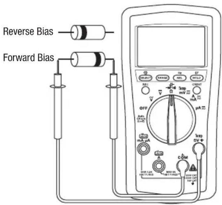
text_image
Reverse Bias Forward Bias SELECT RANGE REF EF REC CRRAT OFF Amp (30A) (1+2) mA μA Max 1.2A MAX 5A HOT PUNED HOT PUNED HOT PUNED MAX 1.2A MAX 5A HOT PUNED HOT PUNED HOT PUNEDTypical Measurements
Temperature
text_image
分 SELECT RANGE MS REF HOLD OFF Auto switch E-A2 V Ω Temp mV A mA μA Δ Temp ΩV+ MGA A COM MAX LGA MAX PASED MAX LGA MAX PASED 100 Ω 100 ΩElectric Field Detection (EF)
text_image
A SELECT RANG REL HOLD REF V OFF Auto Max mA μA max A COM MAX CAN HRC PUNED MAX 50 HRC PUNED MAX 50 HRC PUNED MAX 50 HRC PUNED MAX 50 A B "U for in A- B-Refer to "Using the Features" for complete instructions.
A-Non-contact OR B-Contact
Accuracy
Refer to the “Specifications” section for operating conditions and temperature coefficient.
Accuracy is specified as follows: ± (a percentage of the reading + a fixed amount) at 23 ^ ± 5 ^ ( 73.4 ^ ± 9 ^ ), 0% to 75% relative humidity.
True RMS Readings: DM-510A AC accuracies are specified from 5% to 100% of the range unless otherwise specified. Frequency must be within the specified bandwidth for non-sinusoidal waveforms. Crest factors are as follows:
- Crest factor < 3 : 1 at full scale
- Crest factor < 6 : 1 at half scale
All Models
AC Voltage DC Voltage
| Range(50 Hz to 400 Hz) | Accuracy Range |
| 60.00 mV ± (1.0% + 0.05 mV) | 60.00 mV ± |
| 600.0 mV ± (1.0% + 0.5 mV) | 600.0 mV ± |
| 6.000 V ± (1.0% + 0.005 V) | 6.000 V ± (0.2 |
| 60.00 V ± (1.0% + 0.05 V) | 60.00 V ± (0.2% |
| 600.0 V ± (1.0% + 0.5 V) | 600.0 V ± (0.2% |
| 1000 V ± (1.0% + 5 V) | 1000 V ± (0.2% + 3 |
Input Impedance: 10 MΩ // 50 pF
Accuracies for DM-510A are specified from 5% to 100% of range
| Accuracy | |
| ± (0.4% + 0.05 mV) | |
| (0.2% + 0.3 mV) | |
| % + 0.003 V) | |
| % + 0.03 V) | |
| + 0.3 V) | |
| 3 V) |
Input Impedance: 10 MΩ // 50 pF
Resistance Diode Test
| Range Accuracy | |
| 600.0 Ω | ± (0.5% + 0.4 Ω) |
| 6.000 kΩ | ± (0.5% + 0.004 kΩ) |
| 60.00 kΩ | ± (0.5% + 0.04 kΩ) |
| 600.0 kΩ | ± (0.5% + 0.4k Ω) |
| 6.000 MΩ | ± (0.7% + 0.004 MΩ) |
| 60.00 MΩ | ± (1.2% + 0.04 MΩ) |
Open Circuit Voltage: 0.45 VDC typical
Measuring Range: 1.000 V
Test Current (typical): 0.56 mA
Open Circuit Voltage: < 1.8 VDC
Accuracy: ± (1.0% + 0.003 V)
Continuity
Tone Threshold: Between 10 Ω and 80 Ω
Response Time: < 32 ms
Accuracy (cont'd)
All Models (cont'd)
AC Current
| Range (50 Hz to 400 Hz) Accuracy Burden Voltage (typical) | |
| 600.0 μA ± (1.0% + 0.3 μA) | 0.1 mV/μA |
| 6000 μA ± (1.0% + 3 μA) | |
| 60.00 mA ± (1.0% + 0.03 mA) | 1.7 mV/mA |
| 600.0 mA ± (1.0% + 0.3 mA) | |
| 6.000 A ± (1.2% + 0.006 A) | 0.03 V/A |
| 8.00 A* ± (1.8% + 0.006 A) |
Accuracies for DM-510A are specified from 5% to 100% of range
* 8 A continuous, > 8 A to 15 A for 30 second max with 5 minutes cool down interval
DC Current
| Range Accuracy Burden Voltage (typical) | ||
| 600.0 μA ± (0.5% +0.5 μA) | 0.1 mV/μA | |
| 6000 μA ± (0.5% + 3 μA) | ||
| 60.00 mA ± (0.5% + 0.05 mA) | 1.7 mV/mA | |
| 600.0 mA ± (0.5% + 0.3 mA) | ||
| 6.000 A ± (1.2% + 0.006 A) | 0.03 V/A | |
| 8.00 A* ± (1.8% + 0.006 A) | ||
* 8 A continuous, > 8 A to 15 A for 30 second max with 5 minutes cool down interval
Frequency —Hz (Line) at ACV, DCV, Current, AutoCheck™ Mode
| Function Sensitivity (Sine RMS) Range | ||
| 6 V 0.4 V | 10 Hz to 10 kHz | |
| 60 V | 4 V | 10 Hz to 50 kHz |
| 600 V | 40 V | 10 Hz to 50 kHz |
| 1000 V | 400 V | 45 Hz to 1 kHz |
| 600 μA | 40 μA | 10 Hz to 10 kHz |
| 6000 μA | 400 μA | 10 Hz to 10 kHz |
| 60 mA | 4 mA | 10 Hz to 10 kHz |
| 600 mA | 40 mA | 10 Hz to 10 kHz |
| 6 A | 1 A | 10 Hz to 1 kHz |
| 10 A | 6 A | 10 Hz to 1 kHz |
Accuracy (cont'd)
All Models (cont'd)
Accuracy of Frequency Ranges
| Display Range Accuracy |
| 10.00 Hz to 65.53 Hz ± (0.03% + 0.03 Hz) |
| 65.5 Hz to 655.3 Hz ± (0.03% + 0.3 Hz) |
| 0.655 kHz to 6.553 kHz ± (0.03% + 0.003 kHz) |
| 6.55 kHz to 50.00 kHz ± (0.03% + 0.03 kHz) |
Frequency—Logic Level Hz (mV Function)
| Range Accuracy | Sensitivity (square wave) | |
| 5.0 Hz to 6.553 Hz ± (0.03% + 0.002 Hz) | 3 V peak | |
| 6.55 Hz to 65.53 Hz ± (0.03% + 0.02 Hz) | ||
| 65.5 Hz to 655.3 Hz ± (0.03% + 0.2 Hz) | ||
| 0.655 kHz to 6.553 kHz ± (0.03% + 0.002 kHz) | ||
| 6.55 kHz to 65.53 kHz ± (0.03% + 0.02 kHz) | ||
| 65.5 kHz to 500.0 kHz ± (0.03% + 0.2 kHz) | ||
| 500.0 kHz to 655.3 kHz ± (0.03% + 0.2 kHz) | 5 V peak | |
| 0.655 MHz to 1.000 MHz ± (0.03% + 0.002 MHz) | ||
Non-contact Electric Field Detection (EF)
| Typical Voltage Bar Graph Indication* Frequency Range | ||
| 10 V to 36 V – | 50 Hz to 60 Hz | |
| 23 V to 83 V | -- | |
| 59 V to 165 V | ---- | |
| 124 V to 330 V | ---- | |
| 250 V to 1000 V | ---- | |
* Bar graph indication and tone are proportional to signal strength
Accuracy (cont'd)
DM-210A and DM-510A Only
Capacitance Temperature
| Range Accuracy Range Accuracy | |||
| 60.00 nF ± (2.0% + 0.05 nF) -50 °C to 1000 °C ± (0.3% + 3 °C) | |||
| 600.0 nF ± (2.0% + 0.5 nF) -58 °F to 1832 °F ± (0.3% + 6 °F) | |||
| 6.000 μF ± (1.5% + 0.005 μF) The accuracy information is for the meter only; refer to the information sheet provided with the temperature probe (purchased separately) for its accuracy | |||
| 60.00 μF ± (1.5% + 0.05 μF) | |||
| 600.0 μF ± (1.5% + 0.5 μF) | |||
| 3000 μF ± (2.0% + 5 μF) | |||
Accuracies are for film capacitors (capacitors with negligible dielectric absorption); measurements of larger capacitors can take up to 30 seconds
DM-510A Only
AC Voltage AutoCheck™ Mode DC Voltage AutoCheck™ Mode
| Range (50/60 Hz) Accuracy Range Accuracy | |||
| 6.000 V ± (1.4% | + 0.005 V) 6.000 V ± (1.3% | + 0.003 V) | |
| 60.00 V | ± (1.4% + 0.05 V) | 60.00 V | ± (1.3% + 0.03 V) |
| 600.0 V | ± (1.4% + 0.5 V) | 600.0 V | ± (1.3% + 0.3 V) |
| 1000 V ± (1.4% | + 5 V) | 1000 V ± (1.3% + 3 V) | |
Input Impedance: Initial 2.5 kΩ // 120 pF typical at voltages up to 50 V; increases with voltage to approximately 375 kΩ at 1000 V AutoCheck™ Trigger Level: >1.0 V (50/60 Hz) typical
Input Impedance: Initial 2.5 kΩ // 120 pF typical at voltages up to 50 V; increases with voltage to approximately 375 kΩ at 1000 V AutoCheck™ Trigger Level: > +1.0 VDC and < -1.0 VDC typical
Resistance AutoCheck™ Mode Record Mode (Voltage and Current) for
| Range Accuracy | |
| 600.0 Ω | ± (1.2% + 1.0 Ω) |
| 6.000 kΩ | ± (1.2% + 0.010 kΩ) |
| 60.00 kΩ | ± (1.2% + 0.10 kΩ) |
| 600.0 kΩ | ± (1.2% + 1.0 kΩ) |
| 6.000 MΩ | ± (1.2% + 0.010 MΩ) |
| 60.00 MΩ | ± (1.2% + 0.10 MΩ) |
Open Circuit Voltage: 0.45 VDC typical AutoCheck™ Trigger Level: < 10.00 MΩ typical
recording signal maximums and minimums ≥ 100 ms in duration
Accuracy: Specified accuracy + 100 digits
Crest Capture (Voltage and Current) for Crests ≥ 5 ms in duration
Accuracy: Specified accuracy ± 150 digits
Specifications
Display: LCD (6000) and 24-segment bar graph
Polarity: Automatic
Sampling Rate:
Numeric Display: 5 per second
Bar Graph Display: 40 per second
Temperature Coefficient: Nominal 0.15 x (specified accuracy) per °C
below 18 °C or above 28 °C
Automatic Power Off: After 34 minutes of inactivity.
To disable this feature, press SELECT while turning the meter on.
Noise Rejection*:
Normal Mode Rejection Ratio > 60 dB at 50 Hz and 60 Hz when measuring DCV
Common Mode Rejection Ratio > 60 dB from 0 Hz to 60 Hz when measuring ACV
Common Mode Rejection Ratio > 100 dB at 0 Hz, 50 Hz and 60 Hz when measuring DCV
Operating Conditions:
Temperature: 0 °C to 40 °C (32 °F to 104 °F)
Relative Humidity (non-condensing): 80% maximum for temperatures up to 31 °C (88 °F), decreasing linearly to 50% maximum at 40 °C (104 °F)
Altitude: 2000 m (6500') maximum
Indoor use only
Pollution Degree: 2
Storage Conditions:
Temperature: -20 °C to 60 °C (-4 °F to 140 °F)
Relative Humidity (non-condensing): 0% to 80%
Remove battery.
Battery: Two 1.5 V batteries (AAA, NEDA 24A or IEC LR03)
Overload Protections:
Volts: 1050 V RMS, 1450 V peak
AutoCheck™, mV, Ω, and Others: 600 V RMS
μA and mA: 0.63 A/500 V fuse, interrupting rating 50 kA, 1/4" x 1-1/4"
A: 10 A/600 V fuse, interrupting rating 100 kA, 13/32" x 1-1/2"
Overvoltage Categories:
ΩV Terminal: Category II 1000 V, Category III 600 V, and Category IV 300 V AC and DC
μA and mA Terminal: Category III 500 VAC and 300 VDC
A Terminal: Category III 600 VAC and 300 VDC
E.M.C: Meets EN61326-1:2006 (EN55022, EN61000-3-2, EN61000-3-3, EN61000-4-2, EN61000-
4-3, EN61000-4-4, EN61000-4-5, EN61000-4-6, EN61000-4-8, EN61000-4-11)
*Noise rejection is the ability to reject unwanted signals, or noise.
- Normal mode voltages are AC signals that can cause inaccurate DC measurements. NMRR (Normal Mode Rejection Ratio) is a measure of the ability to filter out these signals.
- Common mode voltages are signals present at the COM and + input terminals, with respect to ground, that can cause digit rattle or offset in voltage measurements. CMRR (Common Mode Rejection Ratio) is a measure of the ability to filter out these signals.
Measurement Categories
These definitions were derived from the international safety standard for insulation coordination as it applies to measurement, control, and laboratory equipment. These measurement categories are explained in more detail by the International Electrotechnical Commission; refer to either of their publications: IEC 61010-1 or IEC 60664.
Measurement Category I
Signal level. Electronic and telecommunication equipment, or parts thereof. Some examples include transient-protected electronic circuits inside photocopiers and modems.
Measurement Category II
Local level. Appliances, portable equipment, and the circuits they are plugged into. Some examples include light fixtures, televisions, and long branch circuits.
Measurement Category III
Distribution level. Permanently installed machines and the circuits they are hard-wired to. Some examples include conveyor systems and the main circuit breaker panels of a building's electrical system.
Measurement Category IV
Primary supply level. Overhead lines and other cable systems. Some examples include cables, meters, transformers, and other exterior equipment owned by the power utility.
Statement of Conformity
Greenlee Textron Inc. is certified in accordance with ISO 9001 (2000) for our Quality Management Systems.
The instrument enclosed has been checked and/or calibrated using equipment that is traceable to the National Institute for Standards and Technology (NIST).
Maintenance
WARNING
Electric shock hazard:
Before opening the case, remove the test leads from the circuit and shut off the unit.
Failure to observe these warnings could result in severe injury or death.
WARNING
Electric shock hazard:
The fuses are an integral part of the overvoltage protection. When fuse replacement is necessary, refer to “Specifications” for the correct type, size, and capacity. Using any other type of fuse will void the overvoltage protection rating of the unit.
Failure to observe this warning could result in severe injury or death.
Replacing the Battery and Fuses
- Disconnect the unit from the circuit. Turn the unit OFF.
- Remove the rubber boot.
- Remove the screw from the back cover.
- Remove the back cover.
- Replace and batteries (observe polarity) and/or fuse(s).
- Replace the cover, screw, and rubber boot.
Cleaning
Periodically wipe the case with a damp cloth and mild detergent; do not use abrasives or solvents.
natural_image
Technical line drawing of a mobile phone casing with battery modules and external casing (no text or symbols)Lifetime Limited Warranty
Greenlee Textron Inc. warrants to the original purchaser of these goods for use that these products will be free from defects in workmanship and material for their useful life, excepting normal wear and abuse. This warranty is subject to the same terms and conditions contained in Greenlee Textron Inc.'s standard one-year limited warranty.
For all Test Instrument repairs, contact Customer Service at +1-815-397-7070 and request a Return Authorization.
For items not covered under warranty (such as items dropped, abused, etc.), a repair cost quote is available upon request.
Note: Prior to returning any test instrument, please check replaceable batteries or make sure the battery is at full charge.
MANUEL D'INSTRUCTIONS

natural_image
Abstract geometric logo with a black diamond containing the letter 'G' (no text or symbols beyond the emblem)GREENLEE®
A Textron Company

text_image
8.000 SELECT RANGE Rel CF REC CREST ~ V Ω Temp mV A mA OFF μA Auto Check (I+2) mA μA Temp DV A- A COM MAX 3.6A MAX 6A MAX 10A MAX 15A MAX 20A MAX 25A MAX 30A MAX 35A MAX 40A MAX 45A MAX 50A MAX 55A MAX 60A MAX 65A MAX 70A MAX 75A MAX 80A MAX 85A MAX 90A MAX 95A MAX 100A MAX 105A MAX 110A MAX 115A MAX 120A MAX 125A MAX 130A MAX 135A MAX 140A MAX 145A MAX 150A MAX 155A MAX 160A MAX 165A MAX 170A MAX 175A MAX 180A MAX 185A MAX 190A MAX 195A MAX 200A MAX 205A MAX 210A MAX 215A MAX 220A MAX 225A MAX 230A MAX 235A MAX 240A MAX 245A MAX 250A MAX 255A MAX 260A MAX 265A MAX 270A MAX 275A MAX 280A MAX 285A MAX 290A MAX 295A MAX 300A MAX 305A MAX 310A MAX 315A MAX 320A MAX 325A MAX 330A MAX 335A MAX 340A MAX 345A MAX 350A MAX 355A MAX 360A MAX 365A MAX 370A MAX 375A MAX 380A MAX 385A MAX 390A MAX 395A MAX 400A MAX 405A MAX 410A MAX 415A MAX 420A MAX 425A MAX 430A MAX 435A MAX 440A MAX 445a MAX 3.6A MAX 6.6B MAX 10.6C MAX 3.6B MAX 6.6C MAX 3.6C MAX 3.6D MAX 3.6E MAX 3.6F MAX 3.6G MAX 3.6H MAX 3.6I MAX 3.6J MAX 3.6K MAX 3.6L MAX 3.6M MAX 3.6N MAX 3.6O MAX 3.6P MAX 3.6Q MAX 3.6R MAX 3.6S MAX 3.6T MAX 3.6U MAX 3.6V MAX 3.6W MAX 3.6X MAX 3.6Y MAX 3.6Z MAX 3.6X MAX 3.6Y MAX 3.6Z MAX 3.6X MAX 3.6Y MAX 3.6Z MAX 3.6X MAX 3.6Y MAX 3.6Z MAX 3.6X MAX 3.6Y MAX 3.6Z MAX 3.6X MAX 3.6Y Max Max Max Max Max Max Max Max Max Max Max Max Max Max Max Max Max Max Max Max Max Max Max Max Max Max Max Max Max Max Max Max Max Max Max Max Max Max Max Max Max Max Max Max Max Max Max Max Max Max Max Max Max Max Max Max Max Max Max Max Max Max Max Max Max Max Max Max Max Max Max Max Max Max Max Max Max Max Max Max Max Max Max Max Max Max Max Max Max Max Max Max Max Max Max Max Max Max Max Max Max MinDM-200A • DM-210A • DM-510A
natural_image
Illustration of a hand interacting with an open book (no text or symbols visible)▲AVERTISSEMENT
natural_image
Simple rounded rectangle outline with no text or symbolstext_image
Diagram of an analog multimeter with labeled components including voltage source, switch, and display screenMesure d'intensité
text_image
Diagram of an electrical testing setup with labeled components including battery, motor, voltmeter, and digital multimeter.Mesures types
text_image
Diagram of a multimeter with labeled components including range selector, voltage meter, and current meter.text_image
Diagram of an analog multimeter with labeled components including probe, range selector, and voltage meterTension c.a. Tension c.c.
Protections antisurcharge :
natural_image
Technical line drawing of a mobile phone casing with battery modules and fuses (no text or symbols)natural_image
Abstract geometric logo with a black diamond containing the letter 'G' (no text or symbols beyond the emblem)GREENLEE®
A Textron Company

text_image
8.000 SELECT RANGE Rel CF REC CREST ~ V Ω Temp mV A mA OFF μA Auto Check (I+2) mA μA Temp DV A- A COM MAX 3.6A MAX 6A MAX 10A MAX 15A MAX 20A MAX 25A MAX 30A MAX 35A MAX 40A MAX 45A MAX 50A MAX 55A MAX 60A MAX 65A MAX 70A MAX 75A MAX 80A MAX 85A MAX 90A MAX 95A MAX 100A MAX 105A MAX 110A MAX 115A MAX 120A MAX 125A MAX 130A MAX 135A MAX 140A MAX 145A MAX 150A MAX 155A MAX 160A MAX 165A MAX 170A MAX 175A MAX 180A MAX 185A MAX 190A MAX 195A MAX 200A MAX 205A MAX 210A MAX 215A MAX 220A MAX 225A MAX 230A MAX 235A MAX 240A MAX 245A MAX 250A MAX 255A MAX 260A MAX 265A MAX 270A MAX 275A MAX 280A MAX 285A MAX 290A MAX 295A MAX 300A MAX 305A MAX 310A MAX 315A MAX 320A MAX 325A MAX 330A MAX 335A MAX 340A MAX 345A MAX 350A MAX 355A MAX 360A MAX 365A MAX 370A MAX 375A MAX 380A MAX 385A MAX 390A MAX 395A MAX 400A MAX 405A MAX 410A MAX 415A MAX 420A MAX 425A MAX 430A MAX 435A MAX 440A MAX 445a MAX 3.6A MAX 6.6B MAX 10.6C MAX 3.6B MAX 6.6C MAX 3.6C MAX 3.6D MAX 3.6E MAX 3.6F MAX 3.6G MAX 3.6H MAX 3.6I MAX 3.6J MAX 3.6K MAX 3.6L MAX 3.6M MAX 3.6N MAX 3.6O MAX 3.6P MAX 3.6Q MAX 3.6R MAX 3.6S MAX 3.6T MAX 3.6U MAX 3.6V MAX 3.6W MAX 3.6X MAX 3.6Y MAX 3.6Z MAX 3.6X MAX 3.6Y MAX 3.6Z MAX 3.6X MAX 3.6Y MAX 3.6Z MAX 3.6X MAX 3.6Y MAX 3.6Z MAX 3.6X MAX 3.6Y MAX 3.6Z MAX 3.6X MAX 3.6Y Max Max Max Max Max Max Max Max Max Max Max Max Max Max Max Max Max Max Max Max Max Max Max Max Max Max Max Max Max Max Max Max Max Max Max Max Max Max Max Max Max Max Max Max Max Max Max Max Max Max Max Max Max Max Max Max Max Max Max Max Max Max Max Max Max Max Max Max Max Max Max Max Max Max Max Max Max Max Max Max Max Max Max Max Max Max Max Max Max Max Max Max Max Max Max Max Max Max Max Max Max MinDM-200A • DM-210A • DM-510A
Multimetri digitali

natural_image
Illustration of a hand interacting with an open book (no text or symbols visible)AVVERTENZA
natural_image
Simple rounded rectangle outline with no text or symbolstext_image
Diagram of an analog multimeter with labeled components including voltage meter, switch, and terminal connectionstext_image
Diagram of an electrical testing setup with battery, motor, and multimeter connected to a motor driveMisure tipiche
text_image
Diagram of a multimeter circuit with labeled components including probe, switch, and voltage meter
text_image
Polarizzazione inversa Polarizzazione in avanti OFF Auto (Check (1+2)) Max mA μA A COM MAX 1.2A HOT PUMED MAX 0A MAX OFF MAX OUT MAX OUTMisure tipiche
Temperatura
text_image
SELECT ANSUR REL OFF REF V Ω Temp mV A mA μA OFF Auto Bode R-10 mA μA Temp ΩV+ A COM MAX 50Hz MAX 50Hz MAX 50Hz MAX 50Hz MAX 50Hz MAX 50Hz MAX 50Hz MAX 50Hz MAX 50Hz MAX 50Hz MAX 50Hz MAX 50Hz MAX 50Hz MAX 50Hz MAX 50Hz MAX 50Hz MAX 50Hz MAX 120Hz MAX 120Hz MAX 120Hz MAX 120Hz MAX 120Hz MAX 120Hz MAX 120Hz MAX 120Hz MAX 120Hz MAX 120Hz MAX 120Hz MAX 120Hz MAX 120Hz MAX 120Hz MAX 120kHz MAX 120kHz MAX 120kHz MAX 120kHz MAX 120kHz MAX 120kHz MAX 120kHz MAX 120kHz MAX 120kHz MAX 120kHz MAX 120kHz MAX 120kHz MAX 120kHz MAX 120kHz MAX 120kHz Max 120kHz Max 120kHz Max 120kHz Max 120kHz Max 120kHz Max 120kHz Max 120kHz Max 120kHz Max 120kHz Max 120kHz Max 120kHz Max 120kHz Max 120kHz Max 120kHz Max 348MHz Max 348MHz Max 348MHz Max 348MHz Max 348MHz Max 348MHz Max 348MHz Max 348MHz Max 348MHz Max 348MHz Max 348MHz Max 348MHz1,0 V (50/60 Hz) tipici
| 6,000 V | ± (1,3% + 0,003 V) |
| 60,00 V | ± (1,3% + 0,03 V) |
| 600,0 V | ± (1,3% + 0,3 V) |
| 1000 V | ± (1,3% + 3 V) |
+1,0 V c.c. e < -1,0 V c.c. tipici
natural_image
Technical line drawing of a mobile phone chassis showing internal components and casing (no text or symbols)natural_image
Abstract geometric logo with a black diamond containing the letter 'G' (no text or symbols beyond the emblem)GREENLEE®
A Textron Company

text_image
8.000 SELECT RANGE Rel CF REC CREST ~ V Ω Temp mV A mA OFF μA Auto Check (I+2) mA μA Temp DV A- A COM MAX 3.6A MAX 6A MAX 10A MAX 15A MAX 20A MAX 25A MAX 30A MAX 35A MAX 40A MAX 45A MAX 50A MAX 55A MAX 60A MAX 65A MAX 70A MAX 75A MAX 80A MAX 85A MAX 90A MAX 95A MAX 100A MAX 105A MAX 110A MAX 115A MAX 120A MAX 125A MAX 130A MAX 135A MAX 140A MAX 145A MAX 150A MAX 155A MAX 160A MAX 165A MAX 170A MAX 175A MAX 180A MAX 185A MAX 190A MAX 195A MAX 200A MAX 205A MAX 210A MAX 215A MAX 220A MAX 225A MAX 230A MAX 235A MAX 240A MAX 245A MAX 250A MAX 255A MAX 260A MAX 265A MAX 270A MAX 275A MAX 280A MAX 285A MAX 290A MAX 295A MAX 300A MAX 305A MAX 310A MAX 315A MAX 320A MAX 325A MAX 330A MAX 335A MAX 340A MAX 345A MAX 350A MAX 355A MAX 360A MAX 365A MAX 370A MAX 375A MAX 380A MAX 385A MAX 390A MAX 395A MAX 400A MAX 405A MAX 410A MAX 415A MAX 420A MAX 425A MAX 430A MAX 435A MAX 440A MAX 445a MAX 3.6A MAX 6.6B MAX 10.6C MAX 3.6B MAX 6.6C MAX 3.6C MAX 3.6D MAX 3.6E MAX 3.6F MAX 3.6G MAX 3.6H MAX 3.6I MAX 3.6J MAX 3.6K MAX 3.6L MAX 3.6M MAX 3.6N MAX 3.6O MAX 3.6P MAX 3.6Q MAX 3.6R MAX 3.6S MAX 3.6T MAX 3.6U MAX 3.6V MAX 3.6W MAX 3.6X MAX 3.6Y MAX 3.6Z MAX 3.6X MAX 3.6Y MAX 3.6Z MAX 3.6X MAX 3.6Y MAX 3.6Z MAX 3.6X MAX 3.6Y MAX 3.6Z MAX 3.6X MAX 3.6Y MAX 3.6Z MAX 3.6X MAX 3.6Y Max Max Max Max Max Max Max Max Max Max Max Max Max Max Max Max Max Max Max Max Max Max Max Max Max Max Max Max Max Max Max Max Max Max Max Max Max Max Max Max Max Max Max Max Max Max Max Max Max Max Max Max Max Max Max Max Max Max Max Max Max Max Max Max Max Max Max Max Max Max Max Max Max Max Max Max Max Max Max Max Max Max Max Max Max Max Max Max Max Max Max Max Max Max Max Max Max Max Max Max Max MinDM-200A • DM-210A • DM-510A
Digital-Multimeter

natural_image
Illustration of a hand interacting with an open book (no text or symbols visible)⚠️WARNUNG
natural_image
Simple rounded rectangle outline with no text or symbolstext_image
Diagram of an analog multimeter with labeled components including voltage meters, switches, and a terminal display.Strommessung

text_image
Diagram of an electrical measurement setup with battery, motor, and multimeter connected to a motor driveTypische Messungen
Widerstandsmessung

text_image
Diagram of a multimeter with labeled components including probe, range selector, and voltage adjustment knobsDurchgangsprüfung

text_image
Diagram of a multimeter with labeled components including probe, range selector, and voltage metertext_image
SELECT RANGE Hg BP HSC RESET V V + 100 mV Ω A mA Ω OFF Active Check (LAD) μA Ω mA μA AMP CDM MAX LTR MAX DTR MAX DTR MAX DTR MAX DTR MAX DTR MAX DTR MAX DTR MAX DTR MAX DTR MAX DTR MAX DTR MAX DTR MAX DTR MAX DTR MAX DTR MAX DTR MAX DTR MAX DTR MAX DTR MAX DTR MAX DTR MAX DTR MAX DTR MAX DTR MAX DTR MAX DTR MAX DTR MAX DTR MAX DTR MAX DTR MIN M MAX DTR MIN M MAX DTR MIN M MAX DTR MIN M MAX DTR MIN M MAX DTR MIN M MAX DTR MIN M MAX DTR MIN M MAX DTR MIN M MAX DTR MIN M MAX DTR MIN M MAX DTR MIN M MAX DTR MIN M MAX DTR MIN M MAX DTR MIN M MAX DTR MIN M MAX DTR MIN M MAX DTH M MAX DTH M MAX DTH M MAX DTH M MAX DTH M MAX DTH M MAX DTH M MAX DTH M MAX DTH M MAX DTH M MAX DTH M MAX DTH M MAX DTH M MAX DTH M MAX DTH M MAX DTH M MAX DTH M MAX DTH M MAX DTH M MAX DTH M MAX DTHE M MAX DTH M MAX DTH M MAX DTH M MAX DTH M MAX DTH M MAX DTH M MAX DTH M MAX DTH M MAX DTH M MAX DTH M MAX DTH M MAX DTH M MAX DTH M MAX DTH M MAX DTH M MAX DTH M MAX DTH M MAX DTH M MAX DTH M MAX DTh M MAX DTh M MAX DTh M MAX DTh M MAX DTh M MAX DTh M MAX DTh M MAX DTh M MAX DTh M MAX DTh M MAX DTh M MAX DTh M MAX DTh M MAX DTh M
text_image
Sperrvor- spannung Durchlass- spannung OFF Amp Charge (1+2) mA μA MAX 1.2A HOT-FUSED Max 5A HOT-FUSED Max 0V HV-CAD HV-CAD HV-CAD OFF SELECT RANGE REF REF HITL2 CRC + - - - - - - - - - - - - - - - - - - - - - - - - - - - - - - - - - - - - - - - - - - - - - - - - - - - - - - - - - - -Typische Messungen
Temperatur

text_image
分 SELECT RANGE REF EF HOLD REC V Ω Temp mV CINT A mA μA OFF Auto Close E-A mA μA A COM Max. 10A Max. 20A Max. 30A Max. 40A Max. 50A Max. 60A Max. 70A Max. 80A Max. 90A Max. 100A Max. 110A Max. 120A Max. 130A Max. 140A Max. 150A Max. 160A Max. 170A Max. 180A Max. 190A Max. 200A Max. 210A Max. 220A Max. 230A Max. 240A Max. 250A Max. 260A Max. 270A Max. 280A Max. 290A Max. 300A Max. 310A Max. 320A Max. 330A Max. 340A Max. 350A Max. 360A Max. 370A Max. 380A Max. 390A Max. 400A Max. 410A Max. 420A Max. 430A Max. 440A Max. 450A Max. 460A Max. 470A Max. 480A Max. 490A Max. 500A Max. 510A Max. 520A Max. 530A Max. 540A Max. 550A Max. 560A Max. 570A Max. 580A Max. 590A Max. 600A Max. 610A Max. 620A Max. 630A Max. 640A Max. 650A Max. 660A Max. 670A Max. 680A Max. 690A Max. 700A Max. 710A Max. 720A Max. 730A Max. 740A Max. 750A Max. 760A Max. 770A Max. 780A Max. 790A Max. 800A Max. 810A Max. 820A Max. 830A Max. 840A Max. 850A Max. 860A Max. 870A Max. 880A Max. 890A Max. 900A Max. 910A Max. 920A Max. 930A Max. 940A Max. 950A Max. 960A Max. 970A Max. 980A Max. 990A Max. 1000Anatural_image
Technical line drawing of a mobile phone casing with battery modules and ventilation slots (no text or symbols)natural_image
Abstract geometric logo with a black diamond containing the letter 'G' (no text or symbols beyond the emblem)GREENLEE®
A Textron Company

text_image
8.000Ω SELECT RANGE No REL EF HOLD REC CREST V Ω Temp mV Ξ A mA Ξ OFF μA Ξ Auto Check (I+2) mA μA Temp DV Ξ A COM MAX 3.6A MAX 6A MAX 10A MAX 15A MAX 20A MAX 25A MAX 30A MAX 35A MAX 40A MAX 45A MAX 50A MAX 55A MAX 60A MAX 65A MAX 70A MAX 75A MAX 80A MAX 85A MAX 90A MAX 95A MAX 100A MAX 105A MAX 110A MAX 115A MAX 120A MAX 125A MAX 130A MAX 135A MAX 140A MAX 145A MAX 150A MAX 155A MAX 160A MAX 165A MAX 170A MAX 175A MAX 180A MAX 185A MAX 190A MAX 195A MAX 200A MAX 205A MAX 210A MAX 215A MAX 220A MAX 225A MAX 230A MAX 235A MAX 240A MAX 245A MAX 250A MAX 255A MAX 260A MAX 265A MAX 270A MAX 275A MAX 280A MAX 285A MAX 290A MAX 295A MAX 300A MAX 305A MAX 310A MAX 315A MAX 320A MAX 325A MAX 330A MAX 335A MAX 340A MAX 345A MAX 350A MAX 355A MAX 360A MAX 365A MAX 370A MAX 375A MAX 380A MAX 385A MAX 390A MAX 395A MAX 400A MAX 405A MAX 410A MAX 415A MAX 420A MAX 425A MAX 430A MAX 435a MAX 3.6A MAX 6.6B MAX 10.6C MAX 15.6D MAX 20.6E MAX 25.6F MAX 28.6G MAX 32.6H MAX 37.6I MAX 40.6J MAX 44.6K MAX 49.6L MAX 54.6M MAX 59.6N MAX 64.6O MAX 69.6P MAX 74.6Q MAX 79.6R MAX 84.6S MAX 89.6T MAX 94.6U MAX 99.6V MAX104.6W MAX109.6X MAX114.6Y MAX119.6Z MAX124.6KDM-200A • DM-210A • DM-510A
natural_image
Illustration of a hand interacting with a closed book (no text or symbols visible)ADVERTENCIA
natural_image
Simple rounded rectangle outline with no text or symbolstext_image
Diagram of an analog multimeter with labeled components including voltage source, switch, and meter dialtext_image
Diagram of an electrical testing setup with labeled components including battery, motor, voltmeter, and digital multimeter.text_image
Diagram of a multimeter with labeled components including range selector, voltage meter, and current meter.text_image
Diagram of a multimeter with labeled components including probe, range selector, and voltage measurement rangestext_image
Diagram of an analog multimeter with labeled components including probe, switch, and display screen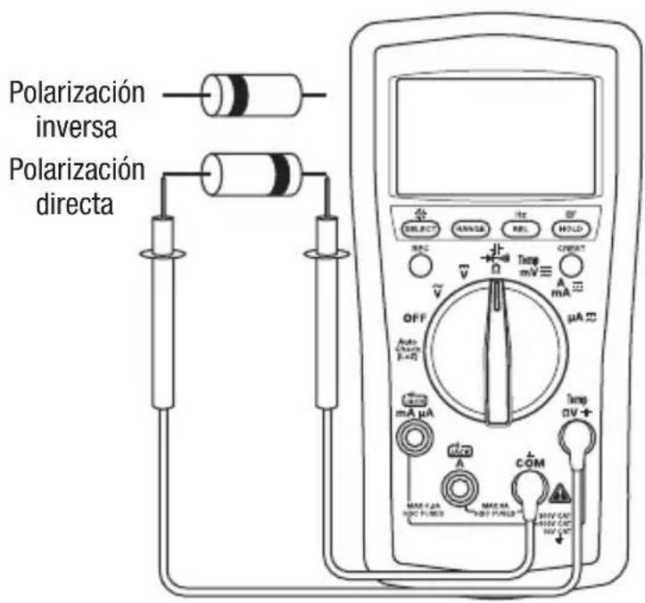
text_image
Polarización inversa Polarización directa SELECT ANSSB REF HOLD REC Temp mV A mA μA OFF Auto [1-2] mA μA Temp DV+ A COM MAX 1.2A HDC FUBS MAX HA HDF FUBS RHO CAT HIV CAT HV CAT| Escala Precision | |
| 600.0 Ω | ± (0.5% + 0.4 Ω) |
| 6.000 kΩ | ± (0.5% + 0.004 kΩ) |
| 60.00 kΩ | ± (0.5% + 0.04 kΩ) |
| 600.0 kΩ | ± (0.5% + 0.4k Ω) |
| 6.000 MΩ | ± (0.7% + 0.004 MΩ) |
| 60.00 MΩ | ± (1.2% + 0.04 MΩ) |
| Escala Precisión | Sensitividad(onda rectangular) | |
| 5.0 Hz a 6.553 Hz ± (0.03% + 0.002 Hz) | 3 V pico | |
| 6.55 Hz a 65.53 Hz ± (0.03% + 0.02 Hz) | ||
| 65.5 Hz a 655.3 Hz ± (0.03% + 0.2 Hz) | ||
| 0.655 kHz a 6.553 kHz ± (0.03% + 0.002 kHz) | ||
| 6.55 kHz a 65.53 kHz ± (0.03% + 0.02 kHz) | ||
| 65.5 kHz a 500.0 kHz ± (0.03% + 0.2 kHz) | ||
| 500.0 kHz a 655.3 kHz ± (0.03% + 0.2 kHz) | 5 V pico | |
| 0.655 MHz a 1.000 MHz ± (0.03% + 0.002 MHz) | ||
natural_image
Technical line drawing of a mobile phone casing with battery module and external casing (no text or symbols)MANUAL DE INSTRUÇÕES

natural_image
Abstract geometric logo with a black diamond containing the letter 'G' (no text or symbols beyond the emblem)GREENLEE®
A Textron Company

text_image
8.000Ω SELECT RANGE Rel CF REC CREST V Ω Temp mV A mA OFF μA Auto Check (I+2) mA μA Temp DV I+ A COM MAX 3.6A MAX 6A MAX 10A MAX 15A MAX 20A MAX 25A MAX 30A MAX 35A MAX 40A MAX 45A MAX 50A MAX 55A MAX 60A MAX 65A MAX 70A MAX 75A MAX 80A MAX 85A MAX 90A MAX 95A MAX 100A MAX 105A MAX 110A MAX 115A MAX 120A MAX 125A MAX 130A MAX 135A MAX 140A MAX 145A MAX 150A MAX 155A MAX 160A MAX 165A MAX 170A MAX 175A MAX 180A MAX 185A MAX 190A MAX 195A MAX 200A MAX 205A MAX 210A MAX 215A MAX 220A MAX 225A MAX 230A MAX 235A MAX 240A MAX 245A MAX 250A MAX 255A MAX 260A MAX 265A MAX 270A MAX 275A MAX 280A MAX 285A MAX 290A MAX 295A MAX 300A MAX 305A MAX 310A MAX 315A MAX 320A MAX 325A MAX 330A MAX 335A MAX 340A MAX 345A MAX 350A MAX 355A MAX 360A MAX 365A MAX 370A MAX 375A MAX 380A MAX 385A MAX 390A MAX 395A MAX 400A MAX 405A MAX 410A MAX 415A MAX 420A MAX 425A MAX 430A MAX 435a MAX 3.6A MAX 6.6B MAX 10.6C MAX 3.6B MAX 6.6C MAX 3.6C MAX 3.6D MAX 3.6E MAX 3.6F MAX 3.6G MAX 3.6H MAX 3.6I MAX 3.6J MAX 3.6K MAX 3.6L MAX 3.6M MAX 3.6N MAX 3.6O MAX 3.6P MAX 3.6Q MAX 3.6R MAX 3.6S MAX 3.6T MAX 3.6U MAX 3.6V MAX 3.6W MAX 3.6X MAX 3.6Y MAX 3.6Z MAX 3.6X MAX 3.6Y MAX 3.6Z MAX 3.6X MAX 3.6Y MAX 3.6Z MAX 3.6X MAX 3.6Y MAX 3.6Z MAX 3.6X MAX 3.6Y MAX 3.6Z MAX 3.6X MAX 3.6Y Max Max Max Max Max Max Max Max Max Max Max Max Max Max Max Max Max Max Max Max Max Max Max Max Max Max Max Max Max Max Max Max Max Max Max Max Max Max Max Max Max Max Max Max Max Max Max Max Max Max Max Max Max Max Max Max Max Max Max Max Max Max Max Max Max Max Max Max Max Max Max Max Max Max Max Max Max Max Max Max Max Max Max Max Max Max Max Max Max Max Max Max Max Max Max Max Max Max Max Max Max MinDM-200A • DM-210A • DM-510A
Multímetros Digitais

natural_image
Illustration of a hand interacting with an open book (no text or symbols visible)ATENÇÃO
natural_image
Simple rounded rectangle outline with no text or symbolstext_image
Diagram of an analog multimeter with labeled components including voltage meters, switches, and a terminal display.text_image
Diagram of an electrical measurement setup with battery, motor, and multimeter connected to a motor drivenatural_image
Simple electrical circuit diagram with two parallel conductors and a cylindrical resistor (no text or symbols)
text_image
分 SELECT ORANGE HX EF REF CONTROL OFF Temp mV A mA μA Max mA μA Temp 0V + Max A COM MAX 2.4A MAX 5A MAX 1.4A MAX 3.4A MAX 6.4A MAX 10A MAX 12A MAX 14A MAX 16A MAX 18A MAX 20A MAX 22A MAX 24A MAX 26A MAX 28A MAX 30A MAX 32A MAX 34A MAX 36A MAX 38A MAX 40A MAX 42A MAX 44A MAX 46A MAX 48A MAX 50A MAX 52A MAX 54A MAX 56A MAX 58A MAX 60A MAX 62A MAX 64A MAX 66A MAX 68A MAX 70A MAX 72A MAX 74A MAX 76A MAX 78A MAX 80A MAX 82A MAX 84A MAX 86A MAX 88A MAX 90A MAX 92A MAX 94A MAX 96A MAX 98A MAX 100 MAX 2.4A MAX 5.4A MAX 10.4A MAX 15.4A MAX 20.4A MAX 25.4A MAX 30.4A MAX 35.4A MAX 40.4A MAX 45.4A MAX 50.4A MAX 55.4A MAX 60.4A MAX 65.4A MAX 70.4A MAX 75.4A MAX 80.4A MAX 85.4A MAX 90.4A MAX 95.4A MAX 100.4natural_image
Technical line drawing of a mobile phone chassis showing battery casing and internal components (no text or symbols)natural_image
Abstract geometric logo with a black diamond containing the letter 'G' (no text or symbols beyond the emblem)GREENLEE®
A Textron Company

text_image
8.000 SELECT RANGE Rel CF REC CREST ~ V Ω Temp mV A mA OFF μA Auto Check (I+2) mA μA Temp DV A- A COM MAX 3.6A MAX 6A MAX 10A MAX 15A MAX 20A MAX 25A MAX 30A MAX 35A MAX 40A MAX 45A MAX 50A MAX 55A MAX 60A MAX 65A MAX 70A MAX 75A MAX 80A MAX 85A MAX 90A MAX 95A MAX 100A MAX 105A MAX 110A MAX 115A MAX 120A MAX 125A MAX 130A MAX 135A MAX 140A MAX 145A MAX 150A MAX 155A MAX 160A MAX 165A MAX 170A MAX 175A MAX 180A MAX 185A MAX 190A MAX 195A MAX 200A MAX 205A MAX 210A MAX 215A MAX 220A MAX 225A MAX 230A MAX 235A MAX 240A MAX 245A MAX 250A MAX 255A MAX 260A MAX 265A MAX 270A MAX 275A MAX 280A MAX 285A MAX 290A MAX 295A MAX 300A MAX 305A MAX 310A MAX 315A MAX 320A MAX 325A MAX 330A MAX 335A MAX 340A MAX 345A MAX 350A MAX 355A MAX 360A MAX 365A MAX 370A MAX 375A MAX 380A MAX 385A MAX 390A MAX 395A MAX 400A MAX 405A MAX 410A MAX 415A MAX 420A MAX 425A MAX 430A MAX 435A MAX 440A MAX 445a MAX 3.6A MAX 6.6B MAX 10.6C MAX 3.6B MAX 6.6C MAX 3.6C MAX 3.6D MAX 3.6E MAX 3.6F MAX 3.6G MAX 3.6H MAX 3.6I MAX 3.6J MAX 3.6K MAX 3.6L MAX 3.6M MAX 3.6N MAX 3.6O MAX 3.6P MAX 3.6Q MAX 3.6R MAX 3.6S MAX 3.6T MAX 3.6U MAX 3.6V MAX 3.6W MAX 3.6X MAX 3.6Y MAX 3.6Z MAX 3.6X MAX 3.6Y MAX 3.6Z MAX 3.6X MAX 3.6Y MAX 3.6Z MAX 3.6X MAX 3.6Y MAX 3.6Z MAX 3.6X MAX 3.6Y MAX 3.6Z MAX 3.6X MAX 3.6Y Max Max Max Max Max Max Max Max Max Max Max Max Max Max Max Max Max Max Max Max Max Max Max Max Max Max Max Max Max Max Max Max Max Max Max Max Max Max Max Max Max Max Max Max Max Max Max Max Max Max Max Max Max Max Max Max Max Max Max Max Max Max Max Max Max Max Max Max Max Max Max Max Max Max Max Max Max Max Max Max Max Max Max Max Max Max Max Max Max Max Max Max Max Max Max Max Max Max Max Max Max MinDM-200A • DM-210A • DM-510A
Digitale multimeters

natural_image
Illustration of a hand interacting with an open book (no text or symbols visible)⚠ WAARSCHUWING
natural_image
Simple rounded rectangle outline with no text or symbolsDe software installeren
text_image
Diagram of an analog multimeter with labeled components including voltage meters, switches, and a terminal display.Stroomsterktemeting

text_image
Diagram of an electrical measurement setup with battery, motor, and multimeter connected to a motor driveTypische metingen
Weerstandmeting

text_image
Diagram of a multimeter with labeled components including probe, range selector, and voltage output terminalstext_image
Diagram of an analog multimeter with labeled components including probe, range selector, and voltage metertext_image
Diagram of a multimeter setup with labeled components including probe, range selector, and voltage meter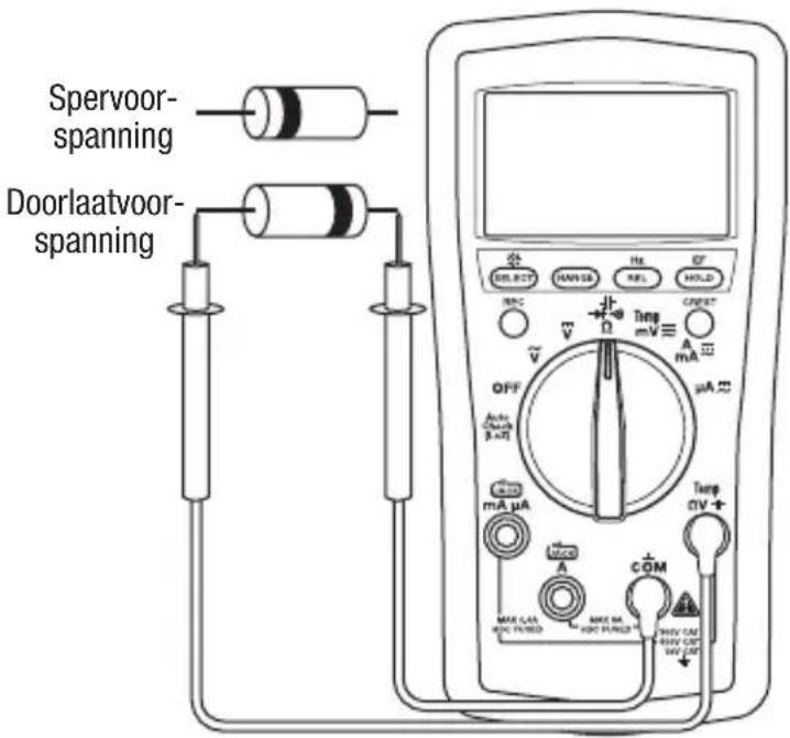
text_image
Spervoor- spanning Doorlaatvoor- spanning OFF mA µA MAX CAN MAX PM MAX PM Max PM Max PM Max PM Max PM Max PM Max PM Max PM Max PM Max PM Max PM Max PM Max PM Max PM Max PM Max PM Max PM Max PM Max PM Max PM Max PM Max PM Max PM Max PM Max PM Max PM Max PM Max PM Max PM Max PM Max PM Max PM Max PM Max PM MaxPM MaxPM MaxPM MaxPM MaxPM MaxPM MaxPM MaxPM MaxPM MaxPM MaxPM MaxPM MaxPM MaxPM MaxPM MaxPM MaxPM MaxPM MaxPM MaxPM MaxPM MaxPM MaxPM MaxPM MaxPM MaxPM MaxPM MaxPM MaxPM MaxPM MaxPM MaxPM MaxPM MaxPMTypische metingen
Temperatuur