DM65 - Multimeter GREENLEE - Free user manual and instructions
Find the device manual for free DM65 GREENLEE in PDF.
User questions about DM65 GREENLEE
0 question about this device. Answer the ones you know or ask your own.
Ask a new question about this device
Download the instructions for your Multimeter in PDF format for free! Find your manual DM65 - GREENLEE and take your electronic device back in hand. On this page are published all the documents necessary for the use of your device. DM65 by GREENLEE.
USER MANUAL DM65 GREENLEE
Read and understand all of the instructions and safety information in this manual before operating or servicing this tool.
The Greenlee DM-65 Digital Multimeter is a hand-held testing device with the following measurement capabilities: AC and DC voltage, AC and DC current, temperature (K-type thermocouples only), frequency, duty cycle, resistance, and capacitance. This meter also checks diodes and verifies continuity.
Other specialized capabilities and functions include:
- Bar graph display.
- Backlighted LCD for reading in dim conditions.
- Relative zero mode.
- Data hold mode.
• Automatic power off.
Safety
Safety is essential in the use and maintenance of Greenlee tools and equipment. This instruction manual and any markings on the tool provide information for avoiding hazards and unsafe practices related to the use of this tool. Observe all of the safety information provided.
Purpose of This Manual
This instruction manual is intended to familiarize all personnel with the safe operation and maintenance procedures for the Greenlee DM-65 Digital Multimeter.
Keep this manual available to all personnel. Replacement manuals are available upon request at no charge at www.greenlee.com.

Do not discard this product or throw away!
For recycling information, go to www.greenlee.com.
All specifications are nominal and may change as design improvements occur. Greenlee Textron Inc. shall not be liable for damages resulting from misapplication or misuse of its products.
® Registered: The color green for electrical test instruments is a registered trademark of Greenlee Textron Inc.
Important Safety Information
SAFETY ALERT SYMBOL
This symbol is used to call your attention to hazards or unsafe practices which could result in an injury or property damage. The signal word, defined below, indicates the severity of the hazard. The message after the signal word provides information for preventing or avoiding the hazard.
DANGER
Immediate hazards which, if not avoided, WILL result in severe injury or death.
WARNING
Hazards which, if not avoided, COULD result in severe injury or death.
CAUTION
Hazards or unsafe practices which, if not avoided, MAY result in injury or property damage.

natural_image
Illustration of a hand interacting with a closed book (no text or symbols visible)WARNING
Read and understand this material before operating or servicing this equipment. Failure to understand how to safely operate this tool could result in an accident causing serious injury or death.

WARNING
Electric shock hazard: Contact with live circuits could result in severe injury or death.
Important Safety Information
WARNING
Electric shock and fire hazard:
- Do not expose this unit to rain or moisture.
- Do not use the unit if it is wet or damaged.
- Use test leads or accessories that are appropriate for the application. Refer to the category and voltage rating of the test lead or accessory.
- Inspect the test leads or accessory before use. They must be clean and dry, and the insulation must be in good condition. Destroy test leads and replace immediately if the contrasting inner layer of insulation is visible.
- Use this unit for the manufacturer's intended purpose only, as described in this manual. Any other use can impair the protection provided by the unit.
Failure to observe these warnings could result in severe injury or death.
WARNING
Electric shock hazard:
- The test leads supplied with this product comply with IEC 61010-031:2008, UL 61010-031:2010 and CAN/CSA-C22.2 NO. 61010-031A-07–Amendment 1:2010. These safety standards limit the exposed length of the probe tip to 4 mm for measurement categories III and IV. These test leads include a cap that must be in place when used in measurement category III or IV applications.
- Do not apply more than the rated voltage between any two input terminals, or between any input terminal and earth ground.
- Do not contact the test lead tips or any uninsulated portion of the accessory.
Failure to observe these warnings could result in severe injury or death.
WARNING
Electric shock hazard:
- Do not operate with the case open.
- Before opening the case, remove the test leads from the circuit and shut off the unit.
Failure to observe these warnings could result in severe injury or death.
Important Safety Information
WARNING
Electric shock hazard:
The fuses are an integral part of the overvoltage protection. When fuse replacement is necessary, refer to “Specifications” for the correct type, size, and capacity. Using any other type of fuse will void the overvoltage protection rating of the unit.
Failure to observe this warning could result in severe injury or death.
WARNING
Electric shock hazard:
- Unless measuring voltage, current, or frequency, shut off and lock out power. Make sure that all capacitors are discharged. Voltage must not be present.
- Set the selector and connect the test leads so that they correspond to the intended measurement. Incorrect settings or connections can result in a blown fuse.
- Using this unit near equipment that generates electromagnetic interference can result in unstable or inaccurate readings.
Failure to observe these warnings could result in severe injury or death.
CAUTION
Electric shock hazard:
Do not change the measurement function while the test leads are connected to a component or circuit.
Failure to observe this precaution may result in injury and can damage the unit.
CAUTION
Electric shock hazard:
- Do not attempt to repair this unit. It contains no user-serviceable parts.
- Do not expose the unit to extremes in temperature or high humidity. Refer to “Specifications.”
Failure to observe these precautions may result in injury and can damage the unit.
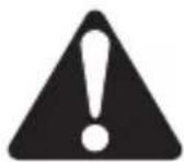
Identification
- Display 6000-count LCD
- Feature buttons Refer to explanations in the "Using the Features" section.
- Selector Selects a function or turns power OFF.
- 10A Positive input terminal for high current measurements.
- COM Negative, common, or ground input terminal for all measurements.
- INPUT Positive input terminal for all measurements except high current.
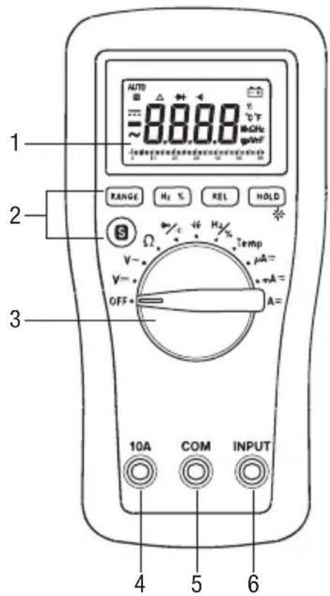
Display Icons
- ▶ Overload symbol for bar graph
- 60 Bar graph scale
- Bar graph element
-
- Polarity indicator for bar graph
- AC measurement is selected.
-
- Polarity indicator
- = DC measurement is selected.
- Hold function is enabled.
- AUTO Automatic ranging is enabled.
- Relative zero function is enabled.
- → Diode
- Continuity
- 8.8.8.8 Numeric display
-
- +ow battery
- % Duty cycle function is enabled.
- °C °F Celsius or Fahrenheit indicator
- M Mega (10 ^5 )
- k Kilo (10 3)
- Ω Ohm
- Hz Hertz (frequency in cycles per second)
- m Milli (10 ^-3 )
- μ Micro (10 ^-6 )
- A Ampere
- V Volt
- n Nano (10 -9)
- F Farad
Symbols on the Unit

Warning—Read the instruction manual

Risk of electric shock

Battery

Fuse

Double insulation
text_image
AUTO 88.88 V~ °C M=CH2 g=CH2 1 2 3 RANGE H2 % REL HOLD S Ω V~ V= OFF Temp μA= mA= mA= A= 10A COM INPUT 4 5 6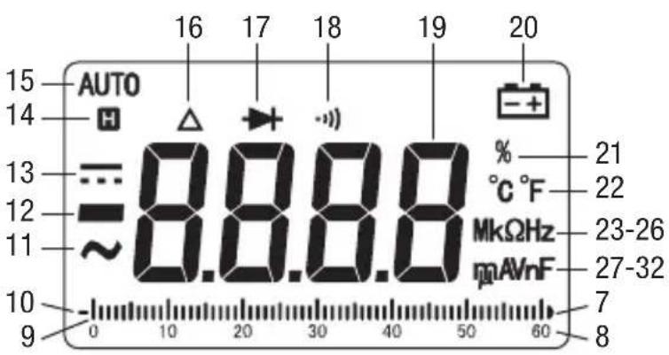
text_image
AUTO H 16 17 18 19 20 15 14 13 =8.8.8.8 % °C °F 21 22 12 ~MkΩHz 23-26 11 mAVnF 27-32 10 - 0 10 20 30 40 50 60 7 8Using the Features
- RANGE: Press once to enter the manual ranging mode. "AUTO" will disappear from the display. Press repeatedly to step through the ranges. Press and hold to return to the automatic ranging mode.
- Hz %: Press momentarily to toggle between frequency and duty cycle functions. This button is active only when the selector is set to Hz/%.
- REL: Finds the difference between two measurements. While taking a measurement, press REL to set the display to zero. “ ” will appear on the display. Take the second measurement. The value on the display will be the difference between the two measurements. Press again to exit this mode.
- HOLD: Press momentarily to hold the present value on the display. Press again to exit this mode.
- *: Press and hold until backlight illuminates. Press and hold again to turn off.
- S: Press momentarily to toggle between functions.
- Automatic Power Off: To extend battery life, the meter will shut itself off after approximately 15 minutes of inactivity. To restore power, press any button or turn the selector to OFF and then back on. To disable this feature, press any button while turning the meter on.
Using the Test Leads
WARNING
Electric shock hazard:
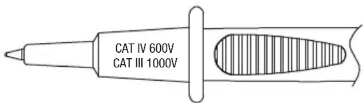
The test leads supplied with this product comply with IEC 61010-031:2008, UL 61010-031:2010 and CAN/CSA-C22.2 NO. 61010-031A-07–Amendment 1:2010. These safety standards limit the exposed length of the probe tip to 4 mm for measurement categories III and IV. These test leads include a cap that must be in place when used in measurement category III or IV applications.
Failure to observe this warning could result in severe injury or death.
Cap must be in place for measurement category III or IV applications.
text_image
CAT IV 600V CAT III 1000V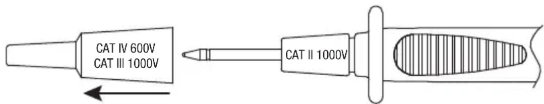
text_image
CAT IV 600V CAT III 1000V CAT II 1000VCap can be removed for measurement category I or II applications.
Operation

WARNING
Electric shock hazard:
Contact with live circuits could result in severe injury or death.
- Refer to the Settings Table. Set the selector to the proper setting, press S (when instructed to do so), and connect the test leads to the meter.
- Refer to "Typical Measurements" for specific measurement instructions.
-
Test the unit on a known functioning circuit or component.
-
If the unit does not function as expected on a known functioning circuit, replace the battery and/or fuses.
-
If the unit still does not function as expected, call Greenlee for technical assistance at 800-435-0786.
-
Take the reading from the circuit or component to be tested.
Operation (cont'd)
Settings Table
| To measure this characteristic ... | Set the selector to this symbol ... | These icons will appear on the display ... | Connect the red lead to ... | Connect the black lead to ... |
| DC Voltage (1000 V max) | V --- | AUTO, and V | INPUT COM | |
| AC Voltage (1000 V max) V | ~ | AUTO, and V INPUT COM | ||
| Resistance Ω AUTO and MΩ INPUT COM | ||||
| Continuity* | → / ··) and press S | ••) and Ω | INPUT COM | |
| Diode | → and V | |||
| Capacitance** | +€ | AUTO and nF INPUT COM | ||
| Frequency | Hz/% and press Hz % | AUTO and Hz | INPUT COM | |
| Duty Cycle % | ||||
| Temperature Temp | AUTO and °C or °F (press S to change scale) | INPUT COM | ||
| Current (6000 μA max)† | μA ≈ | AUTO μA, or= ~ | INPUT COM | |
| Current (600 mA max)† | mA ≈ | AUTO mA, or= ~ | INPUT COM | |
| Current (10 A max)† | A ≈ | AUTO A, or= ~ | 10A COM | |
* Tone indicates continuity. The threshold is between 20 Ω and 150 Ω.
** Discharge capacitor before measurement. Discharge a large capacitor through an appropriate resistive load.
† Press S for AC or DC, as required.
Typical Measurements
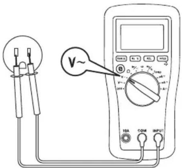
AC Voltage Measurement DC Voltage Measurement
text_image
V~ 10A COM INPUT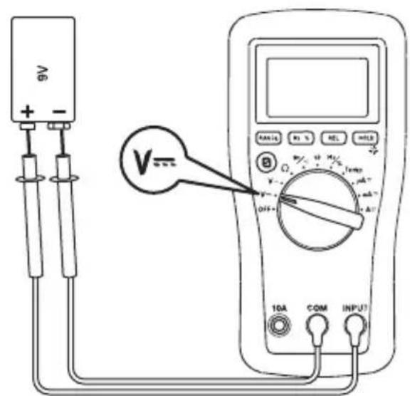
text_image
A6 + - V= OFF- 10A COM INPUTCurrent Measurement
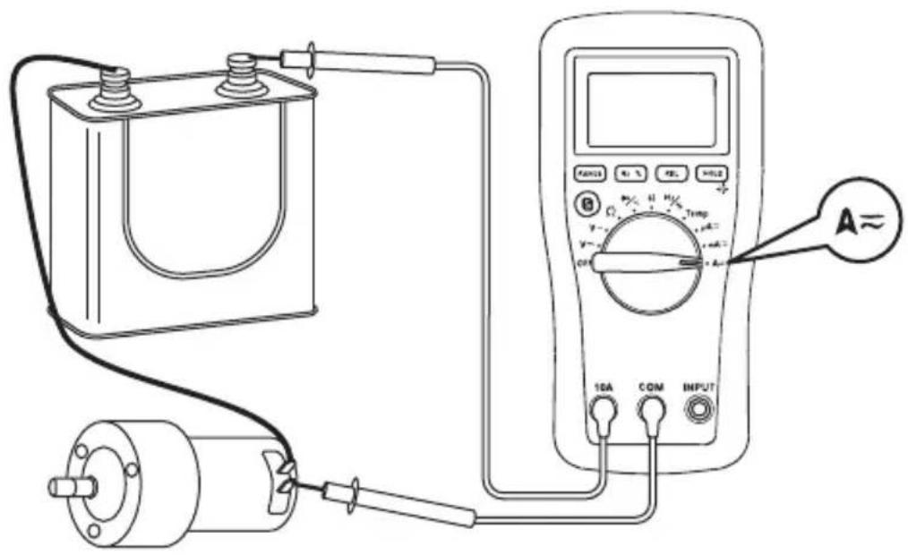
text_image
Diagram of an electrical testing setup with a battery, motor, and multimeter connected to a power supply labeled A≈Typical Measurements
Resistance Measurement
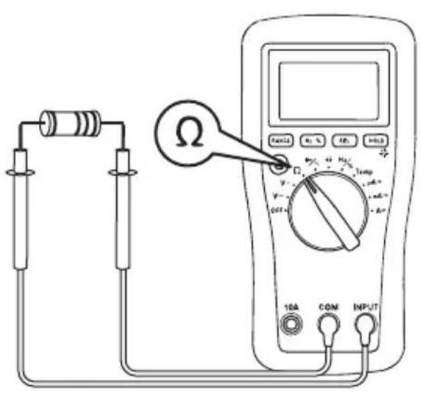
text_image
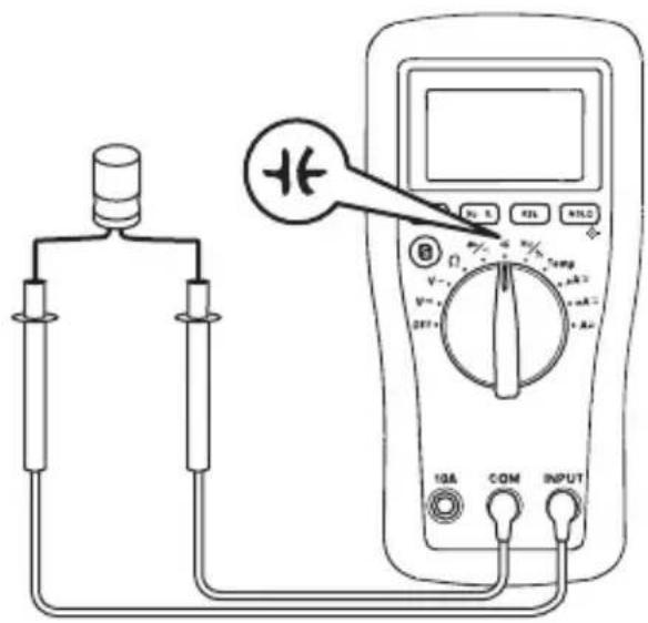
Diagram of a multimeter setup with labeled components including resistors, a switch, and a digital multimeter displaying resistance values.Continuity Check
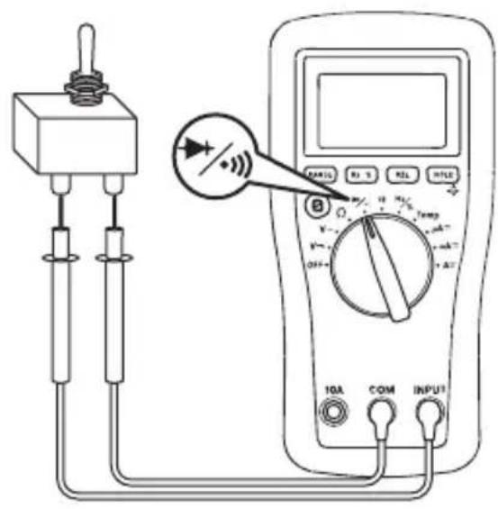
text_image
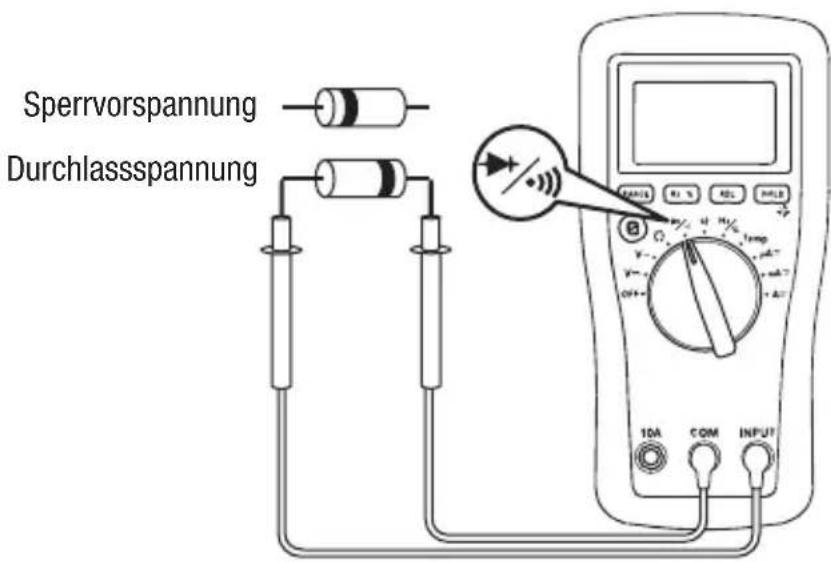
Diagram of a multimeter setup with labeled components including switch, resistors, and digital displayCapacitance Measurement Diode Measurement
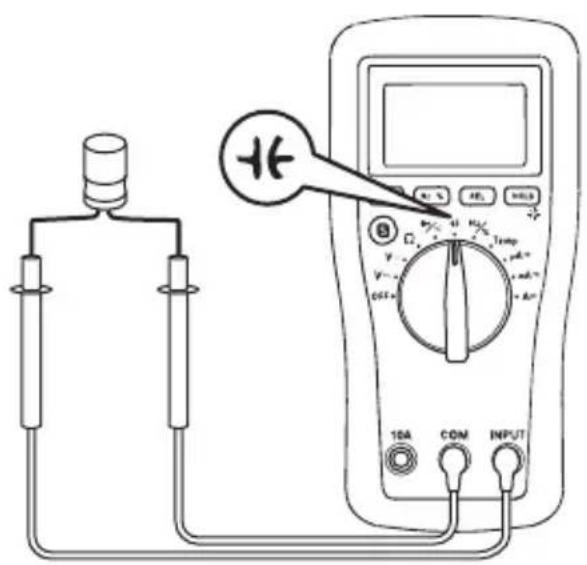
text_image
Diagram showing a multimeter connected to a device with labeled components including 10A, COM, and INPUT terminals.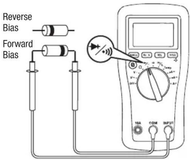
text_image
Reverse Bias Forward Bias TGA COM INPUTTypical Measurements
Temperature
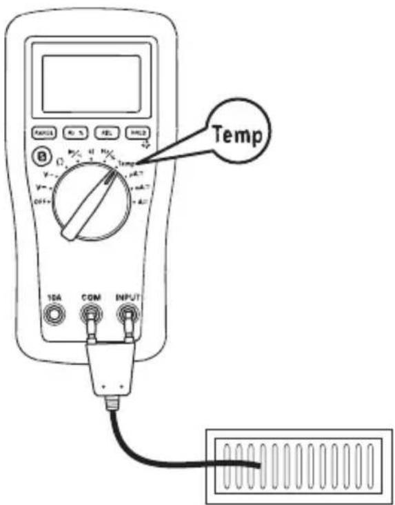
text_image
Temp 10A COM INPUTAccuracy
Refer to the “Specifications” section for operating conditions and temperature coefficient.
Accuracy is specified as follows: ± (a percentage of the reading + a fixed amount) at 23 ^ ± 5 ^ ( 73.4 ^ ± 9 ^ ), 0% to 75% relative humidity.
Accuracy is specified from 5% to 100% of the range unless noted otherwise.
AC Voltage DC Voltage
| Range(40 Hz to 400 Hz) | Accuracy Range | Accuracy | |
| 6.000 V ± (0.8% | + 0.005 V) 600.0 mV ± (0.8% | + 0.5 mV) | |
| 60.00 V ± (1.2% | + 0.05 V) 6.000 V ± (0.8% + 0.005 V) | ||
| 600.0 V ± (1.2% | + 0.5 V) 60.00 V ± (0.8% + 0.05 V) | ||
| 1000 V* ± (1.2% | + 5 V) 600.0 V ± (0.8% + 0.5 V) | ||
| Input Impedance: 10 MΩ, < 100 pF 1000 V* ± (1.0% + 5 V) | |||
* 1000 V range is specified from 20% to 100% of range.
Input Impedance: 10 MΩ, < 100 pF
* 1000 V range is specified from 20% to 100% of range.
Resistance
| Range Accuracy | |
| 600.0 Ω | ± (1.0% + 0.5 Ω) |
| 6.000 kΩ | ± (1.0% + 0.005 kΩ) |
| 60.00 kΩ | ± (1.0% + 0.05 kΩ) |
| 600.0 kΩ | ± (1.0% + 0.5 kΩ) |
| 6.000 MΩ | ± (1.5% + 0.005 MΩ) |
| 60.00 MΩ | ± (3.0% + 0.10 MΩ) |
Open Circuit Voltage: < 0.7 VDC
Diode Test
Measuring Range: 2.000 V
Test Current (typical): 0.8 mA
Open Circuit Voltage (typical): < 3 V
Continuity
Tone Threshold: Between 20 Ω and 150 Ω
Accuracy (cont'd)
AC Current
| Range (40 Hz to 400 Hz) Accuracy Burden Voltage (typical) | |
| 600.0 μA ± (1.8% + 1.0 μA) | 51 μV/μA |
| 6000 μA ± (1.8% + 10 μA) | |
| 60.00 mA ± (1.8% + 0.10 mA) | 2.2 mV/mA |
| 600.0 mA* ± (1.8% + 1.0 mA) | |
| 6.000 A** ± (2.5% + 0.010 A) | 0.03 V/A |
| 10.00 A** ± (2.5% + 0.10 A) |
* 440 mA continuous, 600 mA for 8 hours maximum.
** 2 A continuous, > 2 A to 10 A for 10 second max with 15 minutes cool down interval. 10.00 A range is specified from 20% to 100% of range.
DC Current
| Range Accuracy Burden Voltage (typical) | |
| 600.0 μA ± (1.0% + 0.7 μA) | 51 μV/μA |
| 6000 μA ± (1.0% + 7 μA) | |
| 60.00 mA ± (1.0% + 0.07 mA) | 2.2 mV/mA |
| 600.0 mA* ± (1.0% + 0.7 mA) | |
| 6.000 A** ± (1.5% + 0.007 A) | 0.03 V/A |
| 10.00 A** ± (1.5% + 0.07 A) |
* 440 mA continuous, 600 mA for 8 hours maximum.
** 2 A continuous, >2 A to 10 A for 10 second max with 15 minutes cool down interval. 10.00 A range is specified from 20% to 100% of range.
Frequency Duty Cycle
| Range Accuracy | |
| 9.999 Hz | ± (1.0% + 0.005 Hz) |
| 99.99 Hz | ± (1.0% + 0.05 Hz) |
| 999.9 Hz | ± (1.0% + 0.5 Hz) |
| 9.999 kHz | ± (1.0% + 0.005 kHz) |
| 99.99 kHz | ± (1.0% + 0.05 kHz) |
| 999.9 kHz | ± (1.0% + 0.5 kHz) |
| 9.999 MHz | Unspecified |
Input Voltage: 1 V rms \~ 20 V rms
Range: 5% \~ 95%
Accuracy: ± (2% + 0.7)
Input Voltage: 4 V \~ 10 V peak to peak
Frequency Range: 4 Hz \~ 1 kHz
Accuracy (cont'd)
Capacitance
| Range Accuracy | |
| 40.00 nF ± (3.5% + 0.20 nF) | |
| 400.0 nF ± (2.5% + 0.5 nF) | |
| 4.000 μF ± (3.5% + 0.005 μF) | |
| 40.00 μF ± (4.0% + 0.05 μF) | |
| 400.0 μF ± (5.0% + 0.5 μF) | |
| 4000 μF Unspecified | |
Press REL before connecting test leads to capacitor.
This compensates for test lead capacitance.
Accuracies are for film capacitors (capacitors with negligible dielectric absorption); measurements of larger capacitors can take up to 10 seconds.
Temperature
| Range Accuracy | ||
| °C | -20 °C ~ 0 °C ± (6.0% + 5 °C) | |
| 0 °C ~ 400 °C ± (1.5% + 4 °C) | ||
| 400 °C ~ 1000 °C ± (1.8% + 5 °C) | ||
| °F | -4 °F ~ 32 °F ± (6.0% + 9 °F) | |
| 32 °F ~ 752 °F ± (1.5% + 7.2 °F) | ||
| 752 °F ~ 1832 °F ± (1.8% + 9 °F) | ||
K-type thermocouple range and accuracy not included.
Thermocouple supplied with meter is rated -50^ to 204^ ( -58^ to 400^ ). Accuracy is ± 2.5^ (4.5 °F) or 0.75% of reading, whichever is greater.
Accuracy specification assumes ambient temperature is between 18 °C and 28 °C and is stable to ±1 °C. For ambient temperature changes of ±5 °C, rated accuracy applies after 1 hour.
Specifications
Display: 6000-count LCD
Polarity: Automatic
Numeric Display Sampling Rate: 3 per second
Temperature Coefficient: Nominal 0.2 x (specified accuracy) per °C below 18 °C or above 28 °C
Automatic Power Off: After 15 minutes of inactivity. To disable this feature, press any button while turning the meter on.
Operating Conditions:
Temperature: 0 °C to 40 °C (32 °F to 104 °F)
Relative Humidity (non-condensing): 75% maximum for temperatures up to 31 °C (88 °F), decreasing linearly to 50% maximum at 40 °C (104 °F)
Altitude: 2000 m (6500') maximum
Indoor use only
Pollution Degree: 2
Storage Conditions:
Temperature: -20^ to 50^ (-4°F to 122^ )
Relative Humidity (non-condensing): 0% to 85%
Remove battery.
Battery: One 9 V battery (6F22)
Overload Protections:
Input Terminal: 440 mA/1000 V fast-acting fuse, minimum interrupting rating 10 kA, 13/32" x 1-1/2" or 13/32" x 1-3/8"
10A Terminal: 11 A/1000 V fast-acting fuse, minimum interrupting rating 20 kA, 13/32" x 1-1/2"
Overvoltage Category: Category III 1000 V, Category IV 600 V
E.M.C: Meets EN61326-1:2006 (EN55022, EN61000-3-2, EN61000-3-3, EN61000-4-2, EN61000-4-3, EN61000-4-4, EN61000-4-5, EN61000-4-6, EN61000-4-8, EN61000-4-11)
Measurement Categories
These definitions were derived from the international safety standard for insulation coordination as it applies to measurement, control, and laboratory equipment. These measurement categories are explained in more detail by the International Electrotechnical Commission; refer to either of their publications: IEC 61010-1 or IEC 60664.
Measurement Category I
Signal level. Electronic and telecommunication equipment, or parts thereof. Some examples include transient-protected electronic circuits inside photocopiers and modems.
Measurement Category II
Local level. Appliances, portable equipment, and the circuits they are plugged into. Some examples include light fixtures, televisions, and long branch circuits.
Measurement Category III
Distribution level. Permanently installed machines and the circuits they are hard-wired to. Some examples include conveyor systems and the main circuit breaker panels of a building's electrical system.
Measurement Category IV
Primary supply level. Overhead lines and other cable systems. Some examples include cables, meters, transformers, and other exterior equipment owned by the power utility.
Statement of Conformity
Greenlee Textron Inc. is certified in accordance with ISO 9001 (2000) for our Quality Management Systems.
The instrument enclosed has been checked and/or calibrated using equipment that is traceable to the National Institute for Standards and Technology (NIST).
Maintenance
WARNING
Electric shock hazard:
Before opening the case, remove the test leads from the circuit and shut off the unit.
Failure to observe this warning could result in severe injury or death.
WARNING
Electric shock hazard:
The fuses are an integral part of the overvoltage protection. When fuse replacement is necessary, refer to “Specifications” for the correct type, size, and capacity. Using any other type of fuse will void the overvoltage protection rating of the unit.
Failure to observe this warning could result in severe injury or death.
Replacing the Battery
- Disconnect the unit from the circuit. Turn the unit OFF.
- Remove the screws from the battery cover.
- Remove the battery cover.
- Replace the battery (observe polarity).
- Replace the battery cover and screws.
Replacing the Fuses
- Disconnect the unit from the circuit. Turn the unit OFF.
- Remove the rubber boot.
- Remove the screws from the battery cover.
- Remove the battery cover.
- Remove the screws from the back cover.
- Remove the back cover.
-
Replace the fuse(s).
-
Replace the back cover and screws, battery cover and screws, and rubber boot.
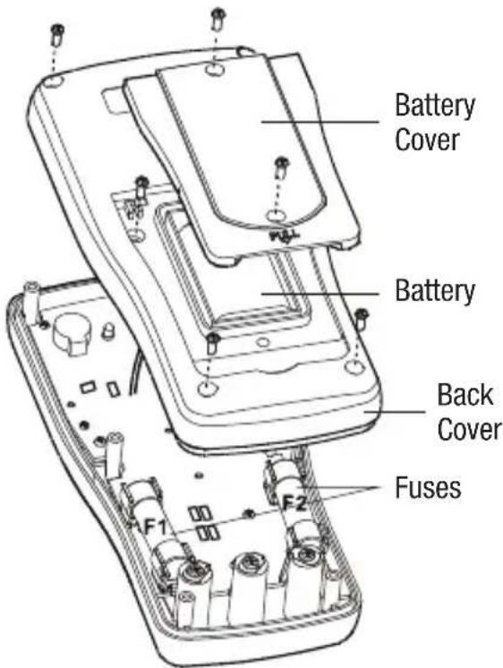
text_image
Battery Cover Battery Back Cover Fuses F1 F2Cleaning
Periodically wipe the case with a damp cloth and mild detergent; do not use abrasives or solvents.
Descripción
natural_image
Illustration of a hand pointing at an open book with visible pages (no text or symbols)ADVERTENCIA
text_image
Diagram of an electrical testing setup with a battery, motor, and multimeter connected to a power supply labeled A≈text_image
Diagram of a multimeter setup with labeled components including resistors, a switch, and a digital multimeter displaying resistance values.text_image
Diagram of a multimeter setup with labeled components including a switch, resistors, and a digital display showing measurement ranges.text_image
Diagram showing a connected device connected to a multimeter with labeled components including 10A, COM, and INPUT terminals.natural_image
Illustration of a hand interacting with an open book (no text or symbols visible)▲AVERTISSEMENT
text_image
Diagram of an electrical testing setup with a battery, motor, and multimeter connected to a power supply labeled A≈Mesures types
text_image
Diagram of a multimeter setup with labeled components including resistors, a switch, and a digital multimeter displaying resistance values.text_image
Diagram of a multimeter setup with labeled components including a switch, resistors, and a digital multimeter displaying readings.text_image
Diagram showing a multimeter connected to a device with labeled components including 10A, COM, and INPUT terminals.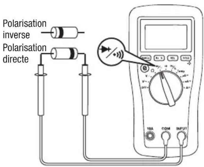
text_image
Polarisation inverse Polarisation directe 10A COM INPUTMesures types
Température

text_image
Temp 10A COM INPUTPrécision
Tension alternative Tension continue
Protections antisurcharge :
natural_image
Illustration of a hand interacting with an open book (no text or symbols visible)⚠️WARNUNG
text_image
Diagram of an electrical testing setup with labeled components including a battery, motor, and multimeter connected to a meter.Typische Messungen
Widerstandsmessung

text_image
Diagram of a multimeter setup with labeled components including resistors, a switch, and a digital multimeter displaying resistance values.Durchgangsprüfung

text_image
Diagram of a multimeter setup with labeled components including switch, resistors, and digital display showing temperature reading.Kapazitätsmessung
text_image
Diagram showing a connected device connected to a multimeter displaying a reading with labeled terminals and a plus symbol indicating the positive terminal.Typische Messungen
Diodenmessung
Lifetime Limited Warranty
Greenlee Textron Inc. warrants to the original purchaser of these goods for use that these products will be free from defects in workmanship and material for their useful life, excepting normal wear and abuse. This warranty is subject to the same terms and conditions contained in Greenlee Textron Inc.'s standard one-year limited warranty.
For all Test Instrument repairs, contact Customer Service at 800-435-0786 and request a Return Authorization.
For items not covered under warranty (such as items dropped, abused, etc.), a repair cost quote is available upon request.
Note: Prior to returning any test instrument, please check replaceable batteries or make sure the battery is at full charge.
An ISO 9001 Company • Greenlee Textron Inc. is a subsidiary of Textron Inc.
Made in China
USA
Tel: 800-435-0786
Fax: 800-451-2632
Canada
Tel: 800-435-0786
Fax: 800-524-2853
International
Tel: +1-815-397-7070
Fax: +1-815-397-9247